Operating instructions Bidirectional Data Interface ... - Mettler Toledo
Operating instructions Bidirectional Data Interface ... - Mettler Toledo
Operating instructions Bidirectional Data Interface ... - Mettler Toledo

You also want an ePaper? Increase the reach of your titles
YUMPU automatically turns print PDFs into web optimized ePapers that Google loves.
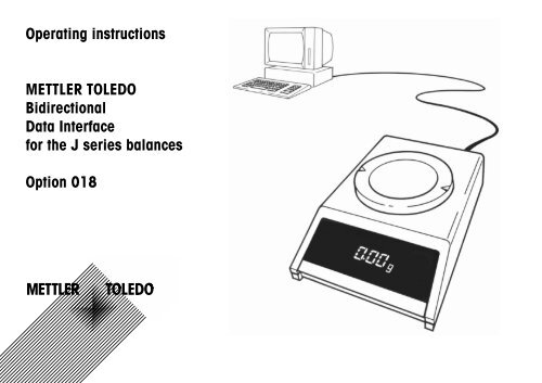
<strong>Operating</strong> <strong>instructions</strong><br />
METTLER TOLEDO<br />
<strong>Bidirectional</strong><br />
<strong>Data</strong> <strong>Interface</strong><br />
for the J series balances<br />
Option 018
2<br />
<strong>Bidirectional</strong> <strong>Data</strong> <strong>Interface</strong> (CL/RS232C) for the J series balances, Option 018<br />
METTLER TOLEDO J series balances can be equipped with a bidirectional interface, Option 018. With a 20 mA current loop or RS232C the J series balance can<br />
transfer the results to a data receiver (computer, terminal, printer, etc.). The balance can also receive <strong>instructions</strong>, and carry them out (full duplex operation). The J<br />
series balance can thus be integrated into a controlled weighing system.<br />
In bidirectional operation the following functions are available:<br />
– automatic transfer of measured results<br />
– taring and pre-taring<br />
– conversation of the weighed result (scaling)<br />
– operation of balance display<br />
The mount the board<br />
Warning: Power cable must be disconnected!<br />
Open balance<br />
- Take off pan (6) and pan support (7). Undo screw (8).<br />
- Lift off upper housing (9) vertically upwards.<br />
- Remove plastic cap (10) at back of balance (push out towards rear).<br />
Caution: Do not touch measuring cell (11)!<br />
Instert board<br />
- Fit board (12) as illustrated, connect connector (13).<br />
- Fit screw (15) in hole (16) and tighten.<br />
Close housing (see upper illustration)<br />
- Carefully lower upper housing on to the balance.<br />
- Insert screw (8) and tighten moderately.<br />
- Put on pan support and pan, connect power cable.
To configure the interface parameters (I-Face)<br />
Once the interface board is in place, the interface parameters shown alongside<br />
can be selected.<br />
Procedure:<br />
– Switch off balance. → Standby Display blank.<br />
– Press control bar<br />
and keep pressed<br />
until<br />
------<br />
-ConF-<br />
appears.<br />
– Release control bar. rESEt appears.<br />
To set standard parameters:<br />
– Press control bar<br />
and keep pressed<br />
until<br />
For other settings:<br />
– After<br />
briefly press control bar.<br />
– Hold control bar down<br />
until the first<br />
parameter appears.<br />
•K((((((g<br />
appears.<br />
appears<br />
(interface).<br />
– To accept displayed parameters → Press control bar until<br />
the next one appears.<br />
– To change parameter → Briefly press control bar.<br />
Preparation<br />
.<br />
K<br />
YES<br />
-EndrESEt<br />
I-FACE<br />
S. Stb<br />
S. ALL<br />
S. Auto<br />
S. Cont<br />
b 110<br />
b 2400<br />
b 9600<br />
P -E-<br />
P -O-<br />
P -M-<br />
P -S-<br />
PSE =0<br />
PSE HS<br />
PSE +0<br />
PSE "0<br />
PrtoFF<br />
Prt on<br />
-End-<br />
}<br />
<strong>Data</strong> transmission mode (see “<strong>Data</strong> output”):<br />
stable single values<br />
current single values (stable or not)<br />
stable single value after each change of weight<br />
all values, continuous<br />
Transmission speed (baud rate):<br />
110 baud<br />
2400 baud<br />
9600 baud<br />
Parity:<br />
Even<br />
Odd<br />
Mark<br />
Space<br />
Interval between data lines and handshake:<br />
for fast data receivers (computers, etc.)<br />
use handshake line<br />
for slow data receivers (printers, etc.)<br />
Print command (to start data transmission):<br />
No start with balance control bar<br />
Start with balance control bar<br />
Hold control bar down till display confirms.<br />
3
Preparation<br />
4<br />
Connection of instruments with current loop interface<br />
The METTLER TOLEDO GA44 printer can (in standard configuration) be connected immediately to the J series<br />
balance. The cable for this is included with the printer (to re-order: Order No. 47926).<br />
For other instruments, the cable has to be ordered separately:<br />
Order No. 47936.<br />
The cable 47936 is connected as shown in the adjoining figure.<br />
It can be used directly for connecting to METTLER TOLEDO CL instruments.<br />
If non-METTLER TOLEDO instruments with a current loop interface are connected to a J series balance, the non-<br />
METTLER TOLEDO instruments must provide the power. In this case the limit figures must be ovserved. They are<br />
described in the section “<strong>Interface</strong>s”.<br />
The wiring diagram here shows how to connect the cable for a non-METTLER TOLEDO instrument with current<br />
loop interfaces.
Connection of instruments with RS232C interface<br />
33640 33995<br />
The cable for instruments with an RS232C interface has to be ordered separately:<br />
Order No. 33640 (male) or 33995 (female)<br />
Made-up cables are obtainable for the following instruments:<br />
Printer EPSON P-40 Order No. 33688<br />
Computer EPSON PX-4 33982<br />
HX-20 33955<br />
Depending on whether the instrument in question is data terminal equipment (DTE) or data communication<br />
equipment (DCE), this cable is connected as follows:<br />
Connections for <strong>Data</strong> Terminal Equipment:<br />
Pin 2: green wire (data input to balance)<br />
Pin 3: brown wire (data output from balance)<br />
Pin 7: white wire (signal ground)<br />
Pin 4 or 20: yellow wire (handshake)<br />
in addition, if required by non-<br />
METTLER TOLEDO instrument:<br />
hard-wire free handshake terminal<br />
(pin 4 or 20)<br />
to pins 5 (CTS), 6 (DSR)<br />
and 8 (DCD).<br />
Connections for <strong>Data</strong> Communications Equipment:<br />
Pin 2: brown wire (data output from balance)<br />
Pin 3: green wire (data input to balance)<br />
Pin 7: white wire (signal ground)<br />
Pin 5 or 6: yellow wire (handshake)<br />
in addition, if required by non-<br />
METTLER TOLEDO instrument:<br />
permanently connect free handshake<br />
terminal pin 5 (CTS) to pin 4 (RTS)<br />
or pin 20 (DTR), or permanently connect<br />
pin 6 (DSR) to pin 4 (RTS) or to<br />
pin 20 (DTR).<br />
Preparation<br />
5
<strong>Interface</strong>s<br />
6<br />
Description of interfaces<br />
The METTLER TOLEDO J series balances has an RS232C voltage-controlled<br />
interface and a passive 20 mA current loop (CL) interface.<br />
These interfaces can be operated in one direction (simplex) or in both directions<br />
(full duplex).<br />
With both interfaces, the data outputs operate in parallel. However, only one of<br />
the inputs can be used at any on time.<br />
The command input is active as soon as the display is switched on. The data<br />
outputs are inactive until the start-up routine has been completed.<br />
Principle of transmission: bit serial, asynchronous (1 start bit)<br />
7-bit code ASCII-ISO646 + parity bit<br />
1 stop bit (receive), 2 stop bits (transmit)<br />
If in bidirectional mode the interface is interrupted for the time of 10 consecutive<br />
characters, this creates a BREAK condition, i.e. all commands initiated via the<br />
interface (transmission mode, pre-tare, text readout, etc.) are Reset. The balance<br />
continues to operate the way it was configured.<br />
How to configure the interface parameters is described in Section “Preparation”.<br />
<strong>Operating</strong> modes: - Free mode operation<br />
- Handshake mode operation<br />
For software handshake, see Technical<br />
Information Bulletin (TIB): “The METTLER TOLEDO<br />
CL <strong>Interface</strong>”. For order no., see introduction to “The<br />
METTLER TOLEDO CL <strong>Interface</strong>”<br />
<strong>Data</strong> loss can be prevented in the following ways, without the need for extra<br />
handshake lines:<br />
1. With “Software Handshake”<br />
2. With an adjustable interval of up to 2 seconds between data strings.<br />
3. By selective request of results with instruction SI C R L F . If the balance cannot<br />
produce a valid result, it immediately sends “SI”. The control computer then<br />
knows that it has to ask again for a measurement.<br />
These operating modes can also be used with the RS232C interface. The<br />
hardware handshake described below can be used as well.
Hardware handshake RS232C<br />
Transfer function with additional key<br />
With the aid of a separate signal line the J series balance can be “slowed down”<br />
when transmitting values via the RS232C interface, i.e. the balance sends data<br />
only when the connected instrument is ready to receive. For this the connected<br />
instrument must support handshake mode, and suitable wiring must be used<br />
(see “Preparation”).<br />
The signal is processed if “PSE HS” has been configured and when the line is<br />
properly connected.<br />
The balance transmits when the handshake line carries a positive voltage or<br />
when it is open. It does not transmit if the voltage is negative. If the level changes<br />
from positive to negative during transmission, a maximum of 2 more characters<br />
are sent.<br />
42500<br />
46278<br />
47473<br />
If this handshake function is used, the transfer function on the right must not be<br />
employed. It is still possible to start data transmission with the control bar on<br />
the balance (configuration: Prt on → Menu: Print).<br />
<strong>Data</strong> transmission can be started with a manual or foot-operated switch. An<br />
adaptor is required in this case (order No. 47473).<br />
Manual switch Order No. 42500<br />
Foot switch 46278<br />
If transfer is started in this way (or with the PRT key on the GA44 Printer), the<br />
handshake function described on the left cannot be used.<br />
More on the initiation of data transmission is to be found in the section “<strong>Data</strong><br />
Retrieval”.<br />
<strong>Interface</strong>s<br />
7
<strong>Interface</strong>s<br />
8<br />
METTLER TOLEDO CL interface<br />
Technical data:<br />
20 mA current loop interface,<br />
full duplex<br />
2 separate data loops<br />
bit serial, asynchronous (1 start bit)<br />
7-bit code (ASCII, ISO-646) + parity bit<br />
inactive state - high level current 20 mA.<br />
The passive current loops of the balance therefore require external power<br />
sources. To avoid damage to the CL interface by these external power sources,<br />
the following limits must be strictly observed:<br />
Interruption of the loop for time T starts character transfer. Transfer of the single<br />
character is terminated by closing the loop again for at least time T.<br />
The CL interface of the balance has two passive loops, independent of each<br />
other.<br />
passive<br />
Balance<br />
Computer<br />
active<br />
The U/I characteristic of the source must lie within the hatched area. To ensure<br />
interference-free transmission, the following conditions must also be satisfied:<br />
- Voltage step of source 15 V (+10 %/ -0 %)<br />
- Current (high) between 18 mA and 24 mA<br />
- Current rate of rise 2…20 mA/µs<br />
- Cable: screened, twisted pairs, approx. 125 Ω/km,<br />
wire dia. (each) 0,14 mm 2 , approx. 130 nF/km,<br />
length: 300 bd 1000 m<br />
2400 bd 500 m<br />
For further information on the METTLER TOLEDO CL interface (hardware and<br />
software aspects), see Technical Information Bulletin (TIB) “The METTLER<br />
TOLEDO CL <strong>Interface</strong>”.<br />
Order No. 720106 German 720107 English<br />
720108 French 720109 Spanish
▼ ▼ ▼ ▼<br />
DCE<br />
The RS232C <strong>Interface</strong><br />
Voltage-controlled interface to standards EIA RS-232-C, DIN 66020<br />
These standards correspond in substance to CCITT recommendations V.24 and<br />
V.28.<br />
A distinction is made between two kinds of equipment:<br />
- DATA TERMINAL EQUIPMENT (DTE), e.g. teletype, printer<br />
- DATA COMMUNICATIONS EQUIPMENT, e.g. modem, transmitter<br />
For short distances, where data communications circuits would be pointless, the<br />
RS232C interface can also be used for two instruments, i.e. the combinations<br />
DTE - DTE and DCE - lines can be omitted. A minimum configuration can be<br />
achieved with two (unidirectional operation) or three lines (bidirectional<br />
operation).<br />
The RS232C interface was originally designed to link data terminal equipment<br />
with data communications equipment. The lines and signals are arranged for<br />
this original configuration, which is still in use today.<br />
In addition to the interface circuits mentioned above, the most common handshake<br />
lines are given below.<br />
1 Protective Ground 1<br />
2 Transmit <strong>Data</strong> TxD 2<br />
▼<br />
3 Receive <strong>Data</strong> RxD 3<br />
4 Request to Send RTS 4<br />
<strong>Data</strong> end<br />
instrument, e.g.,<br />
teletype<br />
<strong>Data</strong> cable<br />
Cable coupling<br />
Chassis connector<br />
Cable connector<br />
Chassis coupling<br />
- A DTE transmits its data at terminal 2<br />
(data direction DTE → DCE)<br />
- A DCE transmits its data at terminal 3<br />
(data direction DCE → DTE)<br />
<strong>Interface</strong>s<br />
<strong>Data</strong> instrument, e.g., modem,<br />
sender, computer<br />
DTE<br />
▼<br />
5 Clear to Send CTS 5<br />
6 <strong>Data</strong> Set Ready DSR 6<br />
7 Signal Ground 7<br />
8 <strong>Data</strong> Carrier Detect DCD 8<br />
20 <strong>Data</strong> Terminal Ready DTR 20<br />
▼<br />
9
<strong>Data</strong> Retrieval<br />
10<br />
Initiation of data transmission<br />
At any moment the balance has available an instantaneous weighing result<br />
which can be stable or unstable, and either valid or invalid. All four combinations<br />
are possible.<br />
Depending on the application, data transmission can be initiated in the following<br />
ways:<br />
- Control bar of the balance (configuration: “Prt on”, Menu: “Print”)<br />
- external print key (Transfer key or “PRT” key on GA44)<br />
- Automatic operation (configuration: “S. Auto”; “S. Cont”)<br />
- Commands via the interface (Send commands)<br />
- Loading or unloading the balance (Send commands “SR”; “SNR”)<br />
In bidirectional operation, these transfer modes can be selected via the interface<br />
with Send commands (described in section “Instruction Set”), regardless of<br />
which transfer mode has been configured.<br />
Transfer mode<br />
* Start transfer with key<br />
Corresponding Send command<br />
S. Stb * S<br />
S. All * SI<br />
S. Auto SNR<br />
S. Cont SIR<br />
The standard setting for data transmission is:<br />
S. Stb A single, stable value is transmitted when data transfer is<br />
started with a key.<br />
The transmission mode can be altered in the configuration register (I-Face):<br />
S.All<br />
A single, instantaneous value (stable or not stable) is<br />
transmitted when data transfer is started with a key.<br />
S. Auto A stable value is transmitted automatically after each<br />
change of weight (threshold 1 g or 5 g in the case of<br />
gram balances).<br />
S. Cont All values are transmitted automatically in time with the<br />
configured interval (unstable values with “SD”, stable<br />
values with “S” in the identification block), see data<br />
format of valid result.<br />
Should the interface link be broken (BREAK) the transfer mode is lost if it was<br />
selected via the interface. The configured transfer mode remains intact, however,<br />
until another one is configured.<br />
Note: The standard setting for the interval between data strings is 1<br />
second (for GA44 Printer).<br />
When operating with a computer, this interval is too long. In most<br />
cases, therefore, it is configured as the minimum (0.0).
Valid result<br />
Each valid weighing result is available in uniform format at the data output. The<br />
data string (series of characters) can be divided into three blocks. It is always<br />
terminated with Carriage Return (CR) and Line Feed (LF).<br />
/ = Space<br />
Identification block <strong>Data</strong> block Unit block<br />
Characters<br />
1 Transfer mode / started with Transfer or Print key<br />
S started with Send commands or<br />
balance in “Send Continuous” mode<br />
(“S. Cont”)<br />
2 Stable state / stable result<br />
D unstable result (dynamic)<br />
4…12 Weighing result 9 characters<br />
Result aligned to the right, including sign<br />
“-” directly ahead of first numeral, decimal<br />
point; leading zeros are replaced by spaces.<br />
With DeltaDisplay or outside the<br />
DeltaRange the last digit is shown as a<br />
space.<br />
14…16 Weight unit 0…3 characters, terminated immediately<br />
with CRLF:<br />
g, %, PCS, Stk, vacant<br />
Example:<br />
SD/ / / -24.375/ gCRLF<br />
Invalid result<br />
Under abnormal operating conditions (e.g. during overload, underload, error<br />
message, etc.) the balance cannot produce a valid weighing result.<br />
The balance responds accordingly, depending on how data transfer is started:<br />
Balance configuration S. All or S. Cont, data transfer started with key (Print, PRT,<br />
Transfer):<br />
/I CRLF invalid result<br />
/I+ CRLF overload<br />
/I- CRLF underload<br />
<strong>Data</strong> transfer started with commands S, SI, SIR or balance in transfer mode<br />
S. Cont:<br />
/I CRLF invalid result<br />
/I+ CRLF overload<br />
/I- CRLF underload<br />
The messages stated above occur immediately after transmission is started. In<br />
all other cases the balance waits until it can provide a valid result.<br />
Special messages from balance<br />
TA CRLF<br />
in bidirectional operation, taring was done with the key<br />
(acknowledgement)<br />
STANDARD//V20.31.00 Switch-on message, software version<br />
ET CRLF<br />
}<br />
ES CRLF Error messages in bidirectional operation<br />
EL CRLF<br />
(➝ “Appendix”)<br />
<strong>Data</strong> Retrieval<br />
11
Instruction Set<br />
12<br />
General information on instruction set<br />
J series balances with Option 018 are equipped with full duplex interfaces, i.e.<br />
they can not only transmit weighing results, but also receive, process and<br />
execute certain control <strong>instructions</strong>.<br />
These <strong>instructions</strong> are described in this section.<br />
A distinction is made between upper and lower case letters.<br />
Each instruction must be terminated with the characters CARRIAGE RETURN (CR)<br />
and LINE FEED (LF).<br />
Note:<br />
Simple specimen programs for bidirectional operation with the J<br />
series balance are given at the end of this section.<br />
The following symbols are used in this section:<br />
/ Space<br />
: = Definition<br />
< > Parameter<br />
[ ] Optional<br />
An instruction without its related parameters normally resets the function in<br />
question.<br />
Instructions which have not yet been executed are overwritten by newly received<br />
<strong>instructions</strong>, i.e. they are lost.<br />
A BREAK condition (see section “<strong>Interface</strong>s”) erases all <strong>instructions</strong> and the<br />
balance then behaves as if it had been switched off and on again.<br />
If the balance does not receive an instruction correctly, or cannot process or<br />
execute it, it emits the appropriate error message (see section “Appendix”).
Instruction: S (Send value)<br />
Instruction: SI (Send Immediate value)<br />
Format:<br />
Function:<br />
Note:<br />
S CRLF<br />
Causes the balance to send the next available stable<br />
result:<br />
- if stable, the value at that moment<br />
- if unstable, the next stable value.<br />
In the case of overload/underload, SI+/SI- is sent<br />
immediately.<br />
This instruction can also be used to cancel other Send<br />
<strong>instructions</strong>.<br />
Example: Computer Balance<br />
S CRLF<br />
Stable<br />
S////100.00/gCRLF<br />
or with overload<br />
SI+CRLF<br />
or with underload<br />
SI-CRLF<br />
Format:<br />
Function:<br />
SI CRLF<br />
On receiving this instruction, the balance transmits the<br />
current result, regardless of whether it is stable or not. The<br />
measured value is marked according to status (see<br />
Section “<strong>Data</strong> Retrieval”).<br />
Example: Computer Balance<br />
SI CRLF<br />
SD////98.54/gCRLF<br />
or if stable<br />
S////100.00/gCRLF<br />
or if invalid<br />
SI CRLF<br />
or with overload<br />
SI+CRLF<br />
or with underload<br />
SI-CRLF<br />
Instruction Set<br />
13
Instruction Set<br />
14<br />
Instruction: SR (Send value and Repeat)<br />
Format:<br />
Function:<br />
Note:<br />
SR CRLF<br />
Causes the balance to send the next available stable<br />
result, and then with each weighing to send automatically<br />
two additional results, namely an unstable, valid result in<br />
the event of significant deflection, followed by the first<br />
stable result.<br />
Significant deflection is taken to be:<br />
+ 12,5 % of the last stable value (relative threshold) or at<br />
least 30d*.<br />
This automatic transfer mode remains in effect until the<br />
balance receives some other Send instruction, or until the<br />
interface is interrupted (BREAK).<br />
Example: Computer Balance<br />
Format:<br />
Function:<br />
SR/CRLF<br />
Causes the balance to send the next available stable<br />
result, and then with each weighing to send automatically<br />
two additional results, namely an unstable, valid result in<br />
the event of significant deflection, followed by the first<br />
stable result.<br />
Note: : = Threshold value in absolute terms<br />
from the last transmitted value, in<br />
weight unit g. Numerical value at<br />
least 3d*.<br />
This automatic transfer mode remains in effect until the<br />
balance receives some other Send instruction, or until the<br />
interface is interrupted (BREAK).<br />
SR CRLF<br />
Stable<br />
S////100.00/gCRLF<br />
Deflection<br />
SD///115.78/gCRLF<br />
Example:<br />
as shown on left, with absolute threshold.<br />
This absolute threshold is recommended particularly with<br />
automatic additive weighing operations, as with SR CRLF<br />
the relative threshold would also become greater with<br />
increasing total weight.<br />
Stable<br />
S////150.00/gCRLF<br />
etc.<br />
* d = digit = smallest step displayed
Instruction: SNR (Send Next value and Repeat)<br />
Instruction: SIR (Send Immediate value and Repeat)<br />
Format:<br />
Function:<br />
Note:<br />
SNR CRLF<br />
Causes the balance to send the next stable result and,<br />
after each loading and unloading, to send automatically<br />
an additional stable result (threshold 1 g or 5 g with<br />
gram balances).<br />
In contrast to the SR instruction, no dynamic values are<br />
transmitted.<br />
This automatic transfer mode remains in effect until the<br />
balance receives some other Send instruction, or until the<br />
interface is interrupted (BREAK).<br />
Example: Computer Balance<br />
SNR CRLF<br />
Stable<br />
Format:<br />
Function:<br />
Note:<br />
SIR CRLF<br />
The balance transmits the instantaneous result in any<br />
case, and then automatically all other results at the same<br />
speed as the balance display (i.e. approx. every 0.16<br />
seconds).<br />
Especially suitable for dynamic weighing. Owing to the<br />
large volume of data from the balance (1 measurement<br />
every 0.16 seconds) the baud rate must be set high<br />
enough not to lose any data.<br />
If a Print interval of 0.0 has not been configured, the<br />
transmission rate is the same as the interval (1 or 2<br />
seconds). Intermediate values are lost.<br />
This automatic transfer mode remains in effect until the<br />
balance receives some other Send instruction, or until the<br />
interface is interrupted (BREAK).<br />
S////100.00/gCRLF<br />
Deflection<br />
min. 1 g<br />
Stable<br />
S////150.00/gCRLF<br />
etc.<br />
Example: Computer Balance<br />
SIR CRLF<br />
SD////98.54/gCRLF<br />
SD////95.76/gCRLF<br />
SD////95.32/gCRLF<br />
S/////95.40/gCRLF<br />
etc.<br />
Instruction Set<br />
15
Instruction Set<br />
16<br />
Instruction: T (Tare)<br />
Instruction: B (Base)<br />
Format:<br />
Function:<br />
Note:<br />
T CRLF<br />
With this instruction the balance can be tared via the<br />
interface.<br />
In the stable condition, taring is immediate.<br />
In an unstable condition, the instruction is stored until<br />
stability is reached, then taring takes place. During this<br />
time an instruction SI or SIR would cause “SI” to be sent.<br />
The error message “EL” follows if stability is not achieved<br />
in about 10 s.<br />
Taring is not possible in the event of overload or under<br />
load. The error message “EL” is given immediately.<br />
If the balance shows -OFF- after a power failure, it can be<br />
started again with this instruction.<br />
Format:<br />
Function:<br />
B [/] CRLF<br />
On receiving this instruction the balance consistently<br />
subtracts the value from all weighing results<br />
(pre-taring).<br />
Note: : = Numerical value, max. 7 significant digits,<br />
sign and decimal point optional.<br />
is in grams (g).<br />
The value must be within the permitted weighing range,<br />
i.e. + tare weight = 0 - maximum load.<br />
is rounded to the balance's resolution before the<br />
results are processed.<br />
B has the same effect as B/0, i.e. it cancels an Offset<br />
instruction. Taring has the same effect.<br />
Example: Computer Balance<br />
T CRLF<br />
Unstable<br />
Display:<br />
------<br />
Wait<br />
Stable<br />
Display:<br />
0.00 g<br />
Example: Computer Balance<br />
Display:<br />
0.00 g<br />
↓<br />
B/100CRLF<br />
Display<br />
-100.00 g<br />
S CRLF<br />
↓<br />
Stable<br />
S///-100.00/gCRLF
Instruction: U (Unit)<br />
Format:<br />
U []/[/[/]]CRLF<br />
U CRLF<br />
Function: Defines a unit with user-selected factor (scaling). Display<br />
no longer shows “g”.<br />
Note: : = Number of decimal places; number is<br />
reduced if greater than resolution.<br />
: = Divisor, by which all weighing results are<br />
divided.<br />
Positive value, at least 1 digit<br />
(display step)<br />
: = #, PCS for transmitting “PCS”<br />
STK, Stk for transmitting “Stk”<br />
% for transmitting “%”<br />
: = Display step in digits:<br />
1, 2, 5, 10, 20, 50, 100<br />
, and are optional.<br />
Without entering , the converted vallues are shown<br />
with the maximum number of decimal places permitted<br />
by the balance. If is not entered, no unit is<br />
displayed.<br />
The factor selected is valid for the displayed values and the values at the data<br />
output until another factor is chosen, U CRLF is transmitted or the interface is<br />
interrupted (BREAK).<br />
Then “g” appears again.<br />
Example: see the end of this section.<br />
Instruction:<br />
Format:<br />
Function:<br />
Note:<br />
ID<br />
ID CRLF<br />
Causes the balance to transmit its identification (3 lines).<br />
The balance transmits:<br />
<br />
TYPE: <br />
INR: <br />
Instruction Set<br />
17
Instruction Set<br />
18<br />
Instruction: D (Display)<br />
Format:<br />
Function:<br />
D/ CRLF<br />
This instruction enables a short text to be displayed.<br />
The balance continues working normally. The execution of<br />
Send <strong>instructions</strong> is not affected.<br />
Note: : = all printable characters of the ISO 646<br />
Code Table.<br />
The only restriction is the limited capacity<br />
of the 7-segment display (see Table on<br />
right)<br />
is displayed aligned to the left.<br />
If is longer than the balance display can show, the<br />
text entered first will not appear.<br />
((((((<br />
7-segment presentation of text characters<br />
The 95 characters of the ISO 646 Code Table printable with a 7-segment<br />
display are shown in the following table.<br />
Caution:<br />
D/CRLF blanks the 7-segment display.<br />
D CRLF resets the display for showing measurements.<br />
Example: Computer Balance<br />
Display<br />
100.00 g<br />
D/TEST CRLF<br />
tESt
Terminal programs for control computers<br />
Example of program for bidirectional communication<br />
The programs listed below enable the computer to work as a simple terminal, so<br />
allowing a direct dialog with the balance.<br />
Task:<br />
Checking of packages containing small parts<br />
<strong>Interface</strong> parameters (standard setting of J series balance):<br />
2400 baud, even parity, 7 data bits and 1 stop bit<br />
Caution:<br />
The punctuation must be strictly adhered to when entering data.<br />
Weight o package (tare)<br />
Weight of each part<br />
Number of parts per package<br />
51.50 g<br />
1.58 g<br />
100 Stk.<br />
Terminal program for IBM-PC<br />
10 Open “com1:2400,E,7,1,CS,CD,DS,RS,LF” AS #1<br />
20 IF LOC(1)>0 THEN PRINT INPUT$(LOC(1),#1);<br />
30 K$=INKEY$ : IF K$“” THEN PRINT#1,K$; : PRINT K$;<br />
50 GOTO 20<br />
Terminal program for Epson HX-20<br />
10 TITLE “TERM”<br />
20 WIDTH20,4<br />
30 OPEN“O“,#1,“COM0 : (57E1F)“<br />
40 OPEN“I“,#2,“COM0 : (57E1F)“<br />
50 IF LOF (2))0 THEN PRINT INPUT$(LOP(2),#2);<br />
60 K$=INKEY$:IFK$““PRINT#1,KS;:PRINTK$;<br />
70 IF K$=CHR$(13)THEN K$=CHR$(10):PRINT#1,K$;:PRINTK$;<br />
80 GOTO 50<br />
Terminal program for Epson PX-4<br />
10 OPEN “O“,#1,“COM0:(C7E1F)“<br />
20 OPEN “I“,#2,“COM0:(C7E1F)“<br />
30 IF LOC (2)>0 THEN PRINT INPUT$(LOC(2),#2);<br />
40 K$=INKEY$ : IF K$““THEN PRINT#1,KS;:PRINT K$;<br />
50 IF K$=CHR$(13) THEN K$=CHR$(10) : PRINT#1,K$; : PRINT K$;<br />
60 GOTO 30<br />
Program in BASIC for Epson PX-4<br />
10 OPEN “I“,#1,“COM0:(C7E1F)“<br />
20 OPEN “O“,#2,“COM0:(C7E1F)“<br />
30 PRINT#2,“B 51.5“<br />
40 PRINT#2,“U0 1.58 PCS 1“<br />
60 PRINT#2,“SR“ : CLS<br />
70 INPUT#1,X$ : PRINT X$<br />
80 GOTO 70<br />
90 END<br />
Users of Epson HX-20 please note:<br />
Only the interface parameter for baud rate (lines 10 and 20) has to be altered:<br />
Change “COM0:(C7E1F)” to “COM0:(57E1F)”<br />
Instruction Set<br />
19
Instruction Set<br />
20<br />
What's gone wrong if …?<br />
When trouble-shooting, consult also the operating <strong>instructions</strong> for the balance.<br />
… one of the following error<br />
messages is transmitted<br />
via the interface?<br />
ES<br />
EL<br />
ET<br />
… data output is too slow/<br />
too fast?<br />
An instruction that has been received is wrong (Syntax Error); the required form of the instruction has not been<br />
observed.<br />
An instruction that has been received is wrong in content (Logistical Error).<br />
The syntax may be correct, but for some reason it cannot be executed.<br />
Example: Tare instruction given with balance overloaded or underloaded.<br />
A character sequence has not been correctly received (Transmission Error):<br />
Probably the transmission parameters of computer and balance interface do not match.<br />
The standard setting for intervals between data strings is 1 second (for GA44 Printer).<br />
The interval can be chosen when configuring (PSE):<br />
0.0, HS, 1, 2 seconds.
Accessories<br />
Thermal printer<br />
(for written records of<br />
weighing data)<br />
Supplied complete with cable<br />
GA44<br />
Connecting cable Current Loop 47936<br />
15 pin - 5 pin<br />
Connecting cable RS232C<br />
15 pin - 25 pin male 33640<br />
female (e.g. for IBM-PC, XT) 33995<br />
Connecting cable for printer<br />
Epson P-40 33688<br />
Connecting cable for computer<br />
Epson HX-20 33955<br />
PX-4 33982<br />
Adapter for data transfer<br />
with connector for foot-operated or manual switch 47473<br />
Foot-operated switch 46278<br />
Manual switch 42500<br />
Appendix<br />
21
Leerseite<br />
22
Leerseite<br />
Printed on 100% chlorine-free Paper, for the sake of our environment.
To give your METTLER TOLEDO product an assured future:<br />
METTLER TOLEDO Service preserves the quality, measurement accuracy and value<br />
of METTLER TOLEDO products for years to come.<br />
Please send for full details of our attractive service conditions.<br />
Thanks in advance<br />
P702742<br />
Subject to technical changes and to the availability<br />
ot the accessoires supplied with the instruments.<br />
© <strong>Mettler</strong>-<strong>Toledo</strong> GmbH 2000 702742 Printed in Switzerland 0011/2.12<br />
<strong>Mettler</strong>-<strong>Toledo</strong> GmbH, Laboratory & Weighing Technologies, CH-8606 Greifensee, Switzerland<br />
Phone +41-1-944 22 11, Fax +41-1-944 30 60, Internet: http://www.mt.com