Bedienungsanleitung BETA PROLINE - Hebetechnik Ges.m.b.H.
Bedienungsanleitung BETA PROLINE - Hebetechnik Ges.m.b.H.
Bedienungsanleitung BETA PROLINE - Hebetechnik Ges.m.b.H.

You also want an ePaper? Increase the reach of your titles
YUMPU automatically turns print PDFs into web optimized ePapers that Google loves.
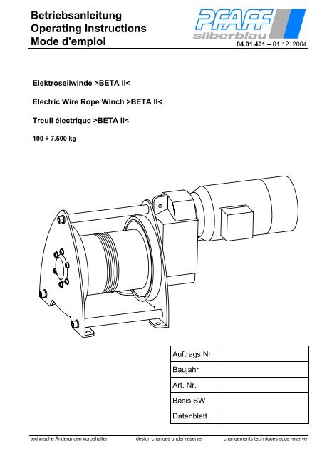
BetriebsanleitungOperating InstructionsMode d'emploi 04.01.401 – 01.12. 2004Elektroseilwinde ><strong>BETA</strong> II<strong>BETA</strong> II<strong>BETA</strong> II
Elektroseilwinde / Electric Wire Rope Winch / Treuil électrique><strong>BETA</strong> II
Elektroseilwinde / Electric Wire Rope Winch / Treuil électrique><strong>BETA</strong> II
Deutsch Elektroseilwinde ><strong>BETA</strong> II< 04.01.401Vor Inbetriebnahme die Betriebsanleitung aufmerksam lesen!Sicherheitshinweise beachten!Dokument aufbewahren!1. Unfallverhütung1.1. Bestimmungsgemäße VerwendungDie Elektroseilwinde ><strong>BETA</strong>< ist eine motorbetriebene Seilwinde für Konsolbefestigung zum Hebenund Senken von Lasten.Nicht geeignet für Einsatz in explosionsgefährdeten Räumen.Nicht geeignet für Einsatz in aggressiver Umgebung.Änderungen an der Seilwinde, sowie das Anbringen von Zusatzgeräten, sind nur mit unsererausdrücklichen schriftlichen Genehmigung erlaubt.!Technische Daten und Funktionsbeschreibung beachten!1.2. UnfallverhütungsvorschriftenEs sind jeweils die im Einsatzland gültigen Vorschriften zu beachten. 1)in Deutschland z.Zt.:BGV D 8 Winden- Hub- und ZuggeräteBGV D 6 KraneBGR 500 Kap. 2.8 Lastaufnahmeeinrichtungen im HebezeugbetriebDIN EN 13155 Lose LastaufnahmemittelDIN 15020 Blatt 1 und Blatt 2EN 60204 T1, El. Ausrüstung von MaschinenEN 60204 T32, El. Ausrüstung von Maschinen-Hebezeuge (VDE 0100 T726)EG Richtlinie 98/37/EGFEM 9.661, ISO 4308/1, ISO 4301/1FEM 9.775, FEM 9.5111) in der jeweils gültigen Fassung1.3. SicherheitshinweiseBedienung, Montage und Wartung nur durch:Beauftragtes, qualifiziertes Personal(Definition für Fachkräfte nach IEC 364)Qualifiziertes Personal sind Personen, die aufgrund ihrer Ausbildung, Erfahrung, Unterweisung sowie Kenntnisse übereinschlägige Normen und Bestimmungen, Unfallverhütungsvorschriften und Betriebsverhältnisse von den für dieSicherheit der Anlage Verantwortlichen berechtigt worden sind, die jeweils erforderliche Tätigkeit auszuführen und dabeimögliche Gefahren erkennen und vermeiden können.Das Befördern von Personen, sowie der Aufenthalt im Gefahrenbereich ist verboten.Aufenthalt unter gehobener Last verboten.Nie in bewegliche Teile greifen.Mängel sind sofort sachkundig zu beheben.1.3.1. Die Last nie in gehobenen Zustand unbeaufsichtigt schweben lassen nie schaukeln lassen darf nie ins Seil fallen nie in Bereiche bewegen, die nicht eingesehen werden können. <strong>Ges</strong>amter Hubbereich muss einschaubarsein.1.3.2. Das Seil3°3° dient nur zum Heben und Senken bzw. Ziehen diverser Lasten und darf zu nichts anderem 1,5°1,5°verwendet werden Bordscheibenüberstand muss mind. das 1,5-fache des Seildurchmessers betragen, regelmäßig nach DIN 15020 Bl. 2 prüfen und warten mind. 3 Seilwindungen müssen bei Last in unterster Stellung immer auf der Trommel bleiben zul. Seilablenkungswinkel (siehe Bild)⇒ bei Standardseil ≤3°; ⇒ bei Spezialseil ≤1,5° Bei ungeführten Lasten drehungsfreie Seile verwenden nicht in Seileinlauf greifen nur mit Schutzhandschuhen anfassen. schlaffes Seil vorsichtig an die Last heranführen3. 2. 1.technische Änderungen vorbehalten Seite 4
Deutsch Elektroseilwinde ><strong>BETA</strong> II< 04.01.4011.3.3. Die WindeTragfähigkeit entsprechend der aufgewickelten Seillage nicht überschreiten.Vor Inbetriebnahme durch Sachkundigen prüfen: Hubgerät Überlastschutzeinrichtung (falls vorhanden) Tragkonstruktion Tragmittel Einbau1.4. ElektroteileElektroanschluss bzw. Reparaturen an Elektroteilen dürfen nur von ausgebildeten Elektrofachleutenausgeführt werden.Die Sicherheitsrichtlinien und Normen des Elektrohandwerkes sind zu beachten.Arbeiten an der Elektroanlage dürfen nur bei freigeschalteter Stromzuführung erfolgen.1.5. Tägliche Prüfungen Funktionsschalter AUF – AB Endschalter (falls vorh.) Not-Aus-Einrichtung Hauptschalter El. Überlastsicherung (falls vorhanden).BeiHublast ab 1.000 kg zwingend erforderlich. Steuerung Bremsenfunktion (Motorbremse) Zustand des Seiles und Lastaufnahmemittels Tragkonstruktion Tragmittel1.6. Das Lastaufnahmemittel auf ausreichende Tragfähigkeit achten Lasthaken müssen Sicherheitsklappen haben Lasthaken muss vorschriftsmäßig mit Seilkausche und Pressklemme mit demSeil verpresst sein. die Last richtig befestigen Windenseil nicht als Anschlagmittel verwenden1.7. Hinweise für SeilendbefestigungenSeilaufhängung und Seilbefestigung: Das Ende eines neu aufgelegten Seilesmuss so ausgelegt sein, dass dauerhaft sichergestellt ist, dass das Seilgefügenicht locker wird.Die Seilendverbindung ist regelmäßig zu prüfen.( Drahtbrüche- Korrosion -Risse- in der Hülse- Lockern der Klemmschrauben usw.)Als Seilendverbindungen dürfen nur verwendet werden⇒Aluminiumpressverbindungen DIN 3093⇒Spleißverbindungen DIN 3089(nicht bekleidet)⇒SeilschlösserSeilschlösser (ähnl. DIN 43148); Seilverbindung mit Nur im Aufzugbauzus. Seilklemme nach DIN 1142 gesichertzulässigA B CAluminiumpressverbindungenDIN 3093SpleißverbindungenDIN 3089(nicht bekleidet)Das freie Seilende ist gegen Durchziehen zu sichern.Die Sicherungsart C ist für Hebezeuge und Lastaufnahmeeinrichtungen nicht erlaubt!⇒ Drahtseilklemmen nach DIN 1142 dürfen als Seilendverbindung imHebezeugbetrieb nicht eingesetzt werden,Mindestens 1x jährlich UVV Prüfung durch Sachkundigen durchführen.Inspektions- und Wartungsintervalle unbedingt einhalten.Nur original Zubehör- und Ersatzteile verwenden, sichere Funktion ansonsten nicht gewährleistet.technische Änderungen vorbehalten Seite 5
Deutsch Elektroseilwinde ><strong>BETA</strong> II< 04.01.4012. Technische DatenSpezifische Technische Daten siehe Tabelle Seite 57 - 65 bzw. beigefügtes Datenblatt.2.1. FunktionsbeschreibungBei der Elektroseilwinde ><strong>BETA</strong>< handelt es sich um Trommelwinden mit Stirnradgetriebe (BG 1 - 5) bzw.mit Schneckengetriebe (BG M 0)Die Last wird durch eine elektromagnetisch lüftende Scheibenbremse in jeder Stellung gehalten.Die Elektroseilwinde kann mit Direktsteuerung, [Drucktastern AUF-AB und NOT-AUS] oder mit einer Elektroschützensteuerung[mit eingebauten Drucktastern AUF-AB, NOT-AUS Taster / Schalter, Hauptschalter] geliefertwerden.Ab 1000 kg Hublast ist eine Schützensteuerung mit elektronischem Überlastschutz erforderlich.Falls erforderlich sind Endschalter vorzusehen.Bei Verwendung von Endschaltern muss die Seilwinde mit Schützensteuerung ausgerüstet werden. Endschalterkönnen bauseitig, bzw. mit angebautem Getriebeendschalter, ausgeführt sein.2.2. Allgemeine technische DatenBaugröße M0 P 1-5 C 1-5 E 1-5Triebwerkgruppe nach DIN 15020 1Bm 2m 1Am 1BmBetriebsart (gem. VDE 530) S3 - 40%max. Schaltungen pro Stunde 120Schutzart IP 54 / 55empf. Seil:• DIN 3060 FE-znk 1770 sZ-spa• DIN 3064 FE-znk 1770 sZ-spageeignet für Umgebungstemperatur• DIN 3069 SE-znk 1960 sZ-spa• DIN 3069 SE-znk 2160 sZ-spa• Spezialseile auf Anfrage lieferbar-20°C÷ +40°CElektroseilwinde ><strong>BETA</strong>< mit 1 <strong>Ges</strong>chwindigkeit für DrehstromMotoranschluss (Standard)Motor:bei 50 Hz 60 Hz 1) Anschlussspannung U ~380-420 V ±5% 50 Hz440-460 V ±5% 60 HzP ≤ 3,0 kW 3,3 kW Y Bremse: Anschluss über EinweggleichrichterP > 3,0 kW 3,3 kW ∆ Spulenspannung U - 170 ÷ 200 V DCElektroseilwinde ><strong>BETA</strong>< mit 2 <strong>Ges</strong>chwindigkeitenMotoranschluss bei 50 Hz Y / YMotor:Bremse: Anschluss über EinweggleichrichterAnschlussspannung U ~ 380-420 V ±5% 50 Hz Spulenspannung U - 170 ÷ 200 V DCElektroseilwinde ><strong>BETA</strong>< mit 1 <strong>Ges</strong>chwindigkeit und EinphasenwechselstromMotoranschluss EinphasenwechselstromMotor:Bremse: Anschluss über EinweggleichrichterAnschlussspannung U ~ 220-240 V ±5% 50 Hz Spulenspannung U - 92 ÷ 110 V DC1)Vor Inbetriebnahme siehe 4.3 Seite 10SchalldruckpegelDer max. Schalldruckpegel [dB(A)], in Abhängigkeitvon der Antriebsleistung, ist dem Diagrammzu entnehmen.Schalldruckpegel / sound level [dB(A)]mechanische Leistung / driving power [kW]technische Änderungen vorbehalten Seite 6
Deutsch Elektroseilwinde ><strong>BETA</strong> II< 04.01.4012.3. HauptabmessungenFür detaillierte Angaben bitte Maßbild anfordernBG 1 - 5BG M 0Type A B ØC D E G[mm] [mm] [mm] [mm] [mm] [mm]BG M 0 185 170 12 5 185 200BG 1 215 300 13,5 6 325 340BG 1.5 215 300 13,5 6 325 340BG 2 270 400 18 8 444 465BG 3 320 510 22 10 547 570BG 3.5 320 510 22 10 547 570BG 4 380 660 26 12 687 720BG 5 430 800 34 15 844 8823. Einbauanleitung3.1. Montage:BEACHTE: Nach Entfernen der Transporthölzer kann die Winde in Richtung Motorkippen, deswegen muss die Winde bei der Montage gegen Kippengesichert werden. Krananhängepunkte beachten! (nicht bei BG M 0) Anbaukonstruktionen für max. Kräfte auslegen(Stoßfaktoren gem. DIN15018 sind zu berücksichtigen) unbedingt auf ebene Anschraubfläche achten. Winde nur mittels Qualitätsschrauben befestigen. Schrauben gleichmäßig anziehen. Schrauben sichern auf unbehinderten Seilablauf achten3.2. Mechanische Befestigung:KrananhängepunkteTransporthölzerBaugröße M0 1 1.5 2 3 3.5 4 5Schrauben M10 M 12 M 12 M 16 M 20 M 20 M 24 M 30Güteklasse min. 8.8Anzahl der Schrauben 4 4 4 4 4 4 4 4Anziehmoment [Nm] 40 70 70 170 340 340 590 1200technische Änderungen vorbehalten Seite 7
Deutsch Elektroseilwinde ><strong>BETA</strong> II< 04.01.4013.3. EinbaulagenDie Seilwinden können in verschiedenen Lagen eingebaut werden.Entlüftungs-, Ölablass- und Ölstandsschraube gem. nachstehenden Abb.Bei BG 1 ist eine Entlüftungsschraube nicht erforderlich.Bei BG M 0 ist keine Änderung der Entlüftungs-, Ölablass- und Ölstandsschraube erforderlich. Getriebe lebensdauergeschmiert.Für alle Einbaulagen geeignet.Auf Ölfüllmenge achten! (siehe Tabelle)H - 01H - 02EntlüftungsschraubeÖlstandsschraubeÖlablassschraubeH - 03 H - 04HauptgetriebeEntlüftungsschraubeÖlablassschraubeÖlstandsschraubeÖlauge (falls vorhanden)Bei einigen Seilwinden ist dem Hauptgetriebeantrieb ein Stirnradgetriebevorgesetzt.Das vorgesetzte Stirnradgetriebe muss bei Veränderung der Einbaulagewie dargestellt angebaut werden.FZ = 2-stufige GetriebeFD = 3-stufige Getriebe3.4. ÖlfüllmengeGetriebeart FZ FD FZ FD FZ FD FZ FDEinbaulageType H - 01 H - 02 H - 03 H - 04BG M0 [l] ca. Schneckengetriebe lebensdauergeschmiertBG 1 [l] ca. 0,7 0,9 0,6 0,6 0,7 0,7 0,6 0,7BG 1.5 [l] ca. 1,6 2,0 1,0 0,9 1,3 1,3 1,3 1,3BG 2 [l] ca. 2,5 3,3 2,3 2,3 2,4 2,4 2,3 2,3BG 3 [l] ca. 4,5 6,3 5,0 5,0 4,8 4,7 4,6 4,7BG 3.5 [l] ca. 7,4 10,6 (0,5*) 9,2 10,6 (0,5*) 8,4 8,2(0,5*) 8,1 8,2BG 4 [l] ca. 13,8 16,8 (1,0*) 13,7 13,5 (1,0*) 15,5 15,2 (1,0*) 14,8 14,8 (1,0*)BG 5 [l] ca. 32,8 44,0 (1,7*) 30,0 28,8 (1,7*) 37,0 36,0 (1,7*) 35,8 35,8 (1,7*)* Ölmenge, vorgesetztes Stirnradgetriebe (falls vorh.)3.5. Drahtseileinlauf90°0°0°270°180°180°Seileinlauf - rechts 270°Seileinlauf - links90°technische Änderungen vorbehalten Seite 8
Deutsch Elektroseilwinde ><strong>BETA</strong> II< 04.01.4013.6. DrahtseilbefestigungACHTUNG:Die Seilwinde hat serienmäßig zwei Seilbefestigungen. Das Seil kann wahlweise, je nach Bedarf, an linkeroder rechter Bordscheibe befestigt werden. Die Seilbefestigung erfolgt mit 2 bzw. 3 Klemmschrauben.Auf richtige Polung des Antriebsmotors achten!BG M 0 und Sonderausführung(mehrseilig)2BG 1 – 5 Standard (einseilig)1 Drahtseil unter Berücksichtigungdes Seileinlaufes in Seilklemmenbohrung einführen. Drahtseil unter Berücksichtigungdes Seileinlaufs einführen Klemmschrauben anziehen.324 Klemmschrauben anziehen Drahtseilende muss aus derSeilklemme herausschauenAnziehmomente der Klemmschrauben Seildurchmesser 4 4; 5; 6 7; 8; 9 10 11; 12; 13; 14 15; 16; 17; 18 19; 20; 21; 22; 23 24Klemmschrauben M 5 M 6 M 8 M 10 M 12 M 16 M 20 M 24Anziehmomente [Nm] 4,8 8,5 20 40 70 170 340 590Die technischen Daten bezüglich Mindestbruchfestigkeit sind entsprechend Typenschild bzw.Hinweis in der <strong>Bedienungsanleitung</strong> einzuhalten!Bei ungeführten Lasten, vor allem bei Einseilaufhängung, muss das Seildrehverhalten bei derAuswahl der Seilart berücksichtigt werden.Je nach gewähltem Seildurchmesser bzw. nach Seillänge, ist bei ungeführten Lasten eindrehungsfreies bzw. drehungsarmes Drahtseil zu verwenden.Seillänge so bemessen, dass in unterster Laststellung mind. 3 Seilwindungen auf der Trommel verbleiben.Max. Seillänge beachten.4. Elektro-InstallationArbeiten an der Elektroanlage dürfen nur: bei freigeschalteter Stromzuführung erfolgen von ausgebildeten Fachkräften des Elektrohandwerks durchgeführt werden.Die Sicherheitsrichtlinien und Normen des Elektrohandwerkes sind zu beachten.In Deutschland gelten hierfür die VDE-Richtlinien.4.1. Einbauhinweis für SchützensteuerungDie Schützensteuerung darf nur mit vertikal stehenden Schützen befestigt werden.Max. Schräglage 22,5°.Zum Ansteuern der Winde ist eine Elektrosteuerung erforderlich.Die Elektroseilwinde wird je nach Auftrag mit Schützensteuerung oder mit Direktsteuerunggeliefert.Sollte die Elektroseilwinde ohne Steuerung geliefert und die Elektrosteuerung bauseitig erstellt werden,sind nachstehende Hinweise sowie die technischen Richtlinien des Verwendungslandes zu beachten.z.B.: EN 60204 T1, T32.Die Verantwortung liegt beim Hersteller des Steuergerätes.4.2. Hinweis EMVDie Elektroseilwinde mit Steuerung ist ausgelegt für Industriebetrieb.Die Norm für elektromagnetische Störemissionen (EN DIN 50081-2), wird bis max. 5 Schaltvorgänge/minerfüllt.Für Anwendung in Verbindung mit elektronischen Schaltkreisen oder Dergleichen bzw. bei mehr als 5Schaltvorgängen/min. sind zusätzliche EMV Maßnahmen (Netzfilter) durchzuführen (bauseitig bzw. alsOption lieferbar).technische Änderungen vorbehalten Seite 9
Deutsch Elektroseilwinde ><strong>BETA</strong> II< 04.01.4014.3. ElektrosteuerungenElektrosteuerungDirektsteuerungmax. Motorleistung 2,2 kWSteuerung mit Wendeschützen,thermischen Motorschutzrelais,Hauptschalter und eingebautenBedienelementenSteuerung mit Wendeschützen,thermischen Motorschutzrelais,Hauptschalter, Hauptschütz undexternen BedienelementenSteuerung mit Wendeschützen,thermischen Motorschutzrelais,Hauptschalter, Hauptschütz undelektronischem Überlastschutz*Steuerung mit Wendeschützen,thermischen Motorschutzrelais,Hauptschalter, Hauptschütz undFunkfernsteuerungSteuerung mit Wendeschützen,thermischen Motorschutzrelais,Hauptschalter, Hauptschütz, elektronischemÜberlastschutz* undFunkfernsteuerung1 <strong>Ges</strong>chwindigkeitund Drehstromanschluss2 <strong>Ges</strong>chwindigkeitenund DrehstromanschlussSchaltplan Nr.1 <strong>Ges</strong>chwindigkeitund Einphasenwechselstrombis 980kg L4.1.401-1760 L4.1.401-1860 L4.1.401-1960Standardbis1000 kgOptionStandardab1000 kgOptionL4.1.401-1700(3) L4.1.401-1800(3) L4.1.401-1900(3)L4.1.401-1720(3) L4.1.401-1820(3) L4.1.401-1920(3)L4.1.401-1740(3) L4.1.401-1840(3) L4.1.401-1940(3)L4.1.401-1723(3) L4.1.401-1823(3) L4.1.401-1923(3)L4.1.401-1743(3) L 4.1.401-1843(3) L4.1.401-1943(3)* Seilwinden mit einer Hublast ab 1000 kg müssen mit Überlastschutz ausgeführt werden.Schützensteuerungen sind ausgelegt für:Winden mit 1 Seilgeschwindigkeit und Drehstrom f=50 Hz: 380÷420 V; f=60 Hz: 440÷460 V; (Seilgeschwindigkeit erhöht sich um Faktor 1,20) Schutzart IP 54; Steuerspannung 42 V - 50/60 HzAchtung:Bei Betrieb der Seilwinde an einem Drehstromnetz U=440÷460 Vmuss die Brücke am Transformator von A÷B nach B÷C gelegt werden!Winden mit 2 Seilgeschwindigkeiten und Drehstrom f=50Hz: 380-420 V ±5%; Schutzart IP 54; Steuerspannung 42 V - 50 HzWinden mit 1 Seilgeschwindigkeit und Einphasenwechselstrom f=50 Hz: 220÷240 V Einphasenwechselstrom Schutzart IP 54 Steuerspannung 24 V - 50 HzTransformatortransformer380-420V 440-460V 380-420V 440-460VZur Versorgung des Steuerstromkreises muss ein Transformator mit galvanischer Trennung verwendetwerden. (in Pfaff-silberblau Steuerungen eingebaut).Ausnahme Direktsteuerung entspr. EN 60204 T32 § 9.1, § 9.2.5.10In jedem Fall muss ein schnell erreichbarer Not-Aus Taster (Schalter) vorgesehen werden (in PfaffsilberblauSteuerungen eingebaut, verschiedene Ausführungen)technische Änderungen vorbehalten Seite 10
Deutsch Elektroseilwinde ><strong>BETA</strong> II< 04.01.4014.4. Not-Aus-SchalterAn jeder Bedienstelle muss eine leicht und schnell erreichbare NOT-AUS Einrichtung vorhandensein. Wo erforderlich, müssen zusätzliche Einrichtungen für NOT-HALT vorgesehen werden z.B. inder Nähe von ungeschützten Seilwinden.4.5. HauptschalterBei Ausführung mit Direktsteuerung ist bauseitig ein Hauptschalter vorzusehen.In Schützensteuerung ist serienmäßig ein Hauptschalter eingebaut.4.6. Hauptstromsicherungen / Zuleitungskabel / SchaltpläneDer Anschluss der Seilwinde hat immer nach mitgelieferten oder bauseitig erstelltemSchaltplan und Klemmenplan zu erfolgen!Jede Elektrosteuerung wird mit dem entsprechendem Schalt- und Klemmenplan geliefert.Basis-Schaltpläne siehe Seite 66 - 84Hauptstromsicherungen sind bauseitig vorzusehen.Zuordnung empfohlene Überstromschutzorgane und Leitungsquerschnitte bei Drehstrom 400V-50Hz(440V-60Hz)Motorleistung(50Hz)P [kW]NennstromI NMittelwerteI A / I NKurzschlussschutz(Sicherungen - Träge)[A]empf. Zuleitungskabel (halogenfreieUmmantelung)min. QuerschnittNYM-J [mm²] Cu0,55 1,6 4,4 4 4 x 1,51,5 3,7 5,4 6 4 x 1,52,2 5,4 5,5 10 4 x 2,53,0 7,2 5,9 16 4 x 2,54,0 9,1 7,0 20 4 x 2,55,5 11,8 6,0 25 4 x 47,5 15,5 6,5 32 4 x 611,0 20 7 40 4 x 1018,5 37 7 63 4 x 1622,0 43 7,2 80 4 x 25Zuordnung empfohlene Überstromschutzorgane und Leitungsquerschnitte bei Einphasenwechselstrom220-240V; 50HzMotorleistung(50Hz) [kW]NennstromI NKurzschlussschutz(Sicherungen - Träge) [A]empf. Zuleitungskabelmin. Querschnitt NYM - J [mm²] Cu0,37 3,0 10 4 x 1,50,55 4,1 10 4 x 1,50,75 5,55 16 4x2,51,0 7,2 16 4x2,5Achtung!Bei größeren Kabellängen, ist zusätzlich der Spannungsfall zu berücksichtigen.Festlegung durch ElektrofachkraftDie Verbindungsleitungen sind in geeigneten Kabelkanälen oder Schutzrohren zu verlegen.Scharfe Kanten , Grate, raue Oberflächen oder Gewinde mit denen die Leiter (Leitungen) in Berührungkommen können, müssen von Leitungskanälen entfernt werden.Bei bauseitiger Steuerungserstellung ist der Schaltplan vom Steuerungshersteller beizustellen.Die gültigen Richtlinien sind zu beachten.Der Anschluss der Seilwinde hat immer nach mitgeliefertem oder bauseitig erstelltem Schaltplan undKlemmenplan zu erfolgen!Option CEE – Stecker (Zuordnung)Auf Phasenfolge und Drehrichtung achten.Motorleistung[kW]CEE – Stecker[A]< 2,0 16 4 x 1,5< 5,0 32 4 x 4< 11,0 63 4 x 10empf. Zuleitungskabel / min. Querschnittz. B. Ölflex – 540 P [mm²]technische Änderungen vorbehalten Seite 11
Deutsch Elektroseilwinde ><strong>BETA</strong> II< 04.01.4014.7. Überlastschutz:Hubvorrichtungen mit einer Hublast ab 1000 kg müssen mit Überlastschutz ausgerüstet werden. Seilwindenfür Hublasten ab 1000kg mit Schützensteuerung sind mit eingebautem elektronischem Überlastschutzausgeführt. Der Überlastschutz wird mit Hilfe eines elektronischen Belastungswächters, der auf 100% bis110% der Anschlussleistung eingestellt wird, ausgelöst. Der eingebaute elektronische Überlastschutz arbeitetmit Anlaufüberbrückung und entbindet den Bediener nicht von der Tragfähigkeits-, Belastungsüberprüfung.Es ist darauf zu achten, dass in der Anlaufphase kein Verhaken der Last erfolgt.Bei Tippbetrieb ist die Überlastabschaltung außer Funktion. Der elektronische Überlastschutz ist eineWarneinrichtung und darf nicht zum regelmäßigem Anfahren von Endstellungen benutzt werden. Zum Anfahrenvon Positionen sind immer wegabhängige Endabschaltungen zu verwenden.Bei der Ermittlung des Überlastfaktors muss die Stetigkeit der Hubeinrichtung in Verbindung mit der max.möglichen Überlastungszeit (Anlaufüberbrückung, Bremszeit usw.) berücksichtigt werden! Die max. Überlastdarf die Obergrenzen der Belastbarkeit des Systems nicht übersteigen. (Die gültigen Normen sind zubeachten) Die Beurteilung des Überlastsystems liegt im Verantwortungsbereich des Herstellers der <strong>Ges</strong>amtanlage.Die im Werk vorgenommene Einstellung des Belastungswächters darf nicht verändert werden.4.8. EndschalterWenn die Endlagen vom Bediener nicht sicher eingesehen werden können, sind Betriebsendschalterzu installieren.Die Endschalter sind funktionsrichtig in den Steuerstromkreis zu integrieren.Je nach Einsatz z. B. in Kränen usw. sind zusätzliche Notendschalter vorgeschrieben. Diese sind entsprechendden jeweiligen Normvorschriften vorzusehen und zu prüfen.Die Verantwortung liegt hier beim Hersteller der <strong>Ges</strong>amtanlage.Bei eingebauten Endschaltern unbedingt die Funktion in Verbindung mit der <strong>Ges</strong>amtanlage prüfen.Bei falscher Polung oder falschem Anschluss sind die Endschalter unwirksam.Die Seilwinden können mit angebautem Getriebeendschalter geliefert werdenAchtung: Seilwinde nicht vor Einstellung und Anschluss der Endschalter betätigen!Bitte beachten: Die Einstellgenauigkeit der Endschalter beträgt je nach Ausf. ca. ±50 mm. Diese Abschaltgenauigkeitkann nur in der ersten Seillage eingehalten werden. Die Winde hat einen Nachlauf, der ca. 1/500 bis 1/100 der Hubgeschwindigkeit [m/min] betragen kann. Es ist unbedingt darauf zu achten, dass die Dehnung des Seiles die Hubendlagen verändern kann. Diebleibende Dehnung des Seiles kann bis zur Ablegreife ca. 1 % der Seillänge betragen. Regelmäßige Prüfung der eingestellten Abschaltwege sind erforderlich!Einstellung: GetriebeendschalterZur Kontakteinstellung ist die Haube des Grenzschalters zu entfernen. Vor derSchaltpunkteinstellung ist sicherzustellen, dass die spannungsführenden Kontaktanschlüssedurch einen Berührungsschutz bzw. bei Flachsteckern durch einevollisolierte Flachsteckhülse abgedeckt sind und es zu keiner Berührung der Anschlüssekommen kann.Der Endschalter ist mit Block- und Einzelkontaktverstellung ausgebildet:Blockverstellung:Mit der schwarzen Einstellschraube (2) kann die Basis aller Nockenscheiben verstellt werden. Die relativeEinstellung der Einzelkontakte zueinander wird dadurch nicht verändert. Bei Rechtsdrehung der schwarzenEinstellschraube um eine Umdrehung erfolgt die Drehung der Nockenscheiben ebenfalls als Rechtsdrehungum 0,575°.Einzelkontaktverstellung:2 1Jedem Kontakt ist eine Nockenscheibe zugeordnet, die stufenlos verstellbar ist. DieNockenscheiben (1) lassen sich, unabhängig voneinander, mit der Verstellschraubeweiß (2) einstellen. Die Einstellung kann ohne vorheriges Lösen irgendwelcherTeile erfolgen. Die Einstellschraube befindet sich in der Selbsthemmung.Die Verstellung der Einstellschraube kann mit Schraubendrehern 10mm oder 4mmsowie Innensechskantschlüssel 4mm erfolgen.Bei Rechtsdrehung der Einstellschraube um eine Umdrehung 360° erfolgt die Drehungder Nockenscheibe ebenfalls als Rechtsdrehung um 2,464° (Blick auf das Hinterteil,die B-Seite des Schalters).Die Nockenscheiben sind so ausgeführt, dass jeweils ein max. Nutzweg und ein Nachlaufweg zur Verfügungsteht. Bei Überschreiten des Nachlaufweges tritt keine Beschädigung des Schalters ein. Es erfolgt jedochwieder die Öffnung oder Schließung des Kontaktes.technische Änderungen vorbehalten Seite 12
Deutsch Elektroseilwinde ><strong>BETA</strong> II< 04.01.4014.9. Bedienelemente:Die Bedienelemente (Steuerplätze) sind so zu installieren,dass vom Bedienerstandplatz der gesamte Lastweg überblicktwerden kann.Drucktaster sind sinnfällig anzuordnen.HebenSenkenNot-AusHebenSenkenNot-AusSchutzmaßnahmen:Anschluss, Schutzmaßnahmen und Absicherung sind nach örtlichen, nationalen und internationalenVorschriften durchzuführen.Vor Inbetriebnahme prüfen: richtige Polung, Drehrichtung, Zuordnung Befehlsgeräte Schutzleitersystem Isolationswiderstand Überlastschutzeinstellung (falls vorhanden) Funktion5. BedienungVor Inbetriebnahme Hauptschalter einschalten. Durch Betätigen des jeweiligen Drucktasters ist diegewünschte Bewegungsrichtung einzuleiten Auf - AbBei Elektroseilwinde mit 2 <strong>Ges</strong>chwindigkeiten sind die Drucktaster ”Auf-Ab” als Stufendrucktasterausgeführt.1. Stufe (halb gedrückt) langsame <strong>Ges</strong>chwindigkeit2. Stufe (ganz gedrückt) schnelle <strong>Ges</strong>chwindigkeitDer Bediener muss während des Betriebes laufend die Last, sowie den Raum unter bzw. über derLast und dem Lastaufnahmemittel beobachten.Sicherheitshinweise siehe 1.3 Seite 4Bei Störungen ist der Betrieb sofort einzustellen und die Störung zu beseitigen.Stets auf richtige Drehrichtung der Seiltrommel achten.Seil niemals falsch aufwickeln.Bei Ansprechen des Überlastschutzes ist die Last zu verringern.In Gefahrensituationen ist der NOT - AUS Schalter zu betätigen.5.1. Direktsteuerung Direktsteuerung bis max. 980 kg max. Motorleistung 2,2 kWHauptschalter (siehe Seite 11) und Motorschutzeinrichtung bauseitig(siehe Seite 21)Not-AusSenkenHebentechnische Änderungen vorbehalten Seite 13
Deutsch Elektroseilwinde ><strong>BETA</strong> II< 04.01.4015.2. Steuerung mit integrierten BedienelementenHauptschalter Not-Aus HauptschalterNot-Aus01 Not-AusAufAufAbAbAn jeder Bedienstelle muss eine leichtund schnell erreichbare NOT-AUSEinrichtung vorhanden sein. Wo erforderlich,müssen zusätzliche Einrichtungenfür NOT-HALT vorgesehenwerden z.B. in der Nähe von ungeschütztenSeilwinden.5.3. Steuerung mit externen BedienelementenHauptschalter1 <strong>Ges</strong>chwindigkeit 2 <strong>Ges</strong>chwindigkeitenAufAbNot-AusAufAbNot-Aus5.4. Steuerung mit funkgesteuerten externen BedienelementenDie Funksteuerung ist nur für Seilwinden zum Heben und Senken vonLasten einsetzbar. Sie darf nicht für Kräne vorgesehen werden.Hier muss eine Kransteuerung mit Zulassung nach ZH 1/547 verwendetwerden.Ein Kran ist ein Hebezeug bei dem die Last mit einem Tragmittel gehobenund zusätzlich in einer oder mehreren Richtungen bewegt werden kann(Begriffsbestimmung siehe BGV D 6).NOT - AUSAufAbSpannungsversorgungU = 2 x 1,5V = 3V DC5.5. Steuerung mit elektronischem Überlastschutz (ab 1000 kg)Der elektronische Überlastschutz ist eingestellt und wird zwischen 100% und 110% der Nennlast wirksam.HauptschalterHauptschalterSchlüsselschalterSchlüsselschalterAufAufNot-AusAbNot-AusAbBei Ansprechen des Überlastschutzes ist die Last zu verringern.Bei Ansprechen des Überlastschutzes ist dieser mittels Schlüsselschalter nach verringern der Last zu entriegeln.Nach dem Entriegeln ist, damit der elektronische Überlastschutz wieder einwandfrei arbeiten kann,eine Pause von mind. 20 Sekunden einzuhalten.Der Schlüssel ist beim Bediener sicher zu verwahren (nicht eingesteckt lassen).Schlüsselschalter darf nicht permanent in Entriegelungsposition gehalten werden.Bei Verlassen des Steuerplatzes ist der Gefahrenbereich unter der Last zu sichern.Nach Beendigung des Einsatzes ist der Hauptschalter auszuschalten und (falls erforderlich)mit Schloss abzusperren!technische Änderungen vorbehalten Seite 14
Deutsch Elektroseilwinde ><strong>BETA</strong> II< 04.01.4016. Inspektions- und WartungsanleitungSicherheitshinweisVor Inspektions- und Wartungsarbeiten ist die Winde durch geeignete Maßnahmen zu entlasten.Arbeiten an der elektrischen Anlage sind nur bei freigeschalteter Stromzuführung durch Elektrofachpersonalerlaubt.Inspektionsintervalletäglich / je Schichtmonatlichvierteljährlichjährlichalle 2000 Betriebsstundenbzw. im 2-jährigenTurnusnach Verbrauch der theoretischenNutzungsdauerWartungs- und InspektionsarbeitenSicherheitsfunktionen Not-Aus, Endschalter, HauptschalterSichtprüfung Seil-Haken (Tragmittel) Tragkonstruktion, ElektrosteuerungSteuerung auf richtige Funktion, Funktionsschalter Auf-Ab, BremsfunktionLeckölverhalten (ist Leckage erkennbar?)Seil gem. DIN 15020 Bl. 2 auf Verschleiß prüfen und wartenSeilbefestigung prüfenSchmiermittelstand kontrollierenBefestigungsschrauben und Bolzenverbindungen auf festen Sitz prüfenMotor prüfenTypenschilder auf Lesbarkeit prüfenLasthaken und Befestigung prüfenVerbrauchten Anteil der theoretischen Nutzungsdauer dokumentieren, Restnutzungsdauerfeststellen und dokumentieren.Bremsenverschleiß prüfen1) z.B. durch Pfaff-silberblau Kundendienst.Überlastschutzeinrichtung (falls vorhanden) prüfenElektrosteuerung - Schaltkontakte, Zustand und Verschleiß prüfen; falls erforderlichSchütze austauschen.Schaltkontakte haben begrenzte LebensdauerSachkundigenprüfung durchführen lassen. 1)Schmiermitteltausch durchführen. Ablassschraube öffnen, altes Schmiermittelentfernen, Ablassschraube einschrauben, über Einfüllschraube neues Schmiermitteleinfüllen. Füllmenge beachten.Nicht bei BG M0 da lebensdauergeschmiertGeneralüberholung durchführen lassen (nur vom Hersteller).Die Lebensdauer der Winde ist begrenzt, verschlissene Teile müssenrechtzeitig erneuert werden.technische Änderungen vorbehalten Seite 15
Deutsch Elektroseilwinde ><strong>BETA</strong> II< 04.01.4016.1. Bremse-VerschleißkontrolleZur Kontrolle des Bremsverschleißes ist regelmäßig der Lüftspalt zu messen und ggf. neu zujustieren!Wenn Lüftspalt nicht mehr nachgestellt werden kann, sind die Bremsscheiben zu erneuern.Arbeiten an der Bremse dürfen nur von hierfür autorisierten Fachkräften ausgeführt werden.FühlerlehreSLÜLüftweg S Lü6.1.1. Einstellen des LüftwegsLüftweg S LüNenn in der Nähe der Schrauben(10) mit Fühlerlehre kontrollierenBei zu großer Abweichung vom Lüftweg,S LüNenn wie folgt nachstellen: Schrauben (10) lösen. Hülsenschrauben (9) mit Maulschlüssel etwasverdrehen. Bei zu großem Lüftweg in das Magnetteil (7). Bei zu kleinem Lüftweg aus dem Magnetteil (7) 1/6 Umdrehung verändert den Lüftweg um ca.0,15mm. Schrauben (10) anziehen. Lüftwegkontrolle wiederholen und fallserforderlich, Lüftweg nochmal nachstellen.Achtung!Ein zu großer Lüftspalt kann dazu führen, dass die Bremsenicht mehr lüftet. Bei weiterem Betreiben ohne Neujustierungder Bremse kommt es zur Überlastung bzw. Zerstörungder Bremse, mit möglichem Absturz der Last.Bei Bedarf <strong>Bedienungsanleitung</strong> der Bremse anfordern!xxxx xxGetriebegrößeTypenschlüssel– xx xx – XX / XBremsentype Lüftweg SLü [mm] max. Nachstellung RotorstärkeMK [Nm] Nenn ±0,05mm max. zul. Verschleißweg min. max.P 5 0,2 0,5 1,5 4,5 6,0L 4 0,2 0,5 1,5 4,5 6,0L 8 0,2 0,5 1,5 5,5 7,0L 16 0,2 0,5 1,5 7,5 9,0L 32 0,3 0,7 2,0 8,0 10,0L 60 0,3 0,8 2,5 7,5 10,0L 80 0,3 1,0 3,5 8,0 11,5L 150 0,4 1,0 3,0 10,0 13,0L 260 0,4 1,2 4,0 12,0 16,0L 400 0,5 1,4 4,5 15,5 20,0MotorgrößeGröße der BremseBremseeingestellt auf______Nmtechnische Änderungen vorbehalten Seite 16
Deutsch Elektroseilwinde ><strong>BETA</strong> II< 04.01.4016.2. Einstufung von Hebezeugen nach Triebwerkgruppen gem. FEM 9.511Die Elektroseilwinden sind in verschiedene Triebwerkgruppen, nach DIN 15020 , FEM 9.511 , ISO 4301/1,eingeordnet. (siehe techn. Daten Seite 6)Diese Triebwerkgruppe bezieht sich auf den Seiltrieb und alle mechanischen Teile der Winde.Sie bestimmt den Zeitraum der sicheren Betriebsperiode in Abhängigkeit vom Lastkollektiv.LaufzeitKlasseLastkollektivNr. Benennung1 leicht2 mittel3 schwerKurzzeichen V 006 V 012 V 025 V 05 V 1 V 2 V 3 V 4 V 5mittlere Laufzeit je Tag in h,bezogen auf 1 Jahr4 sehrschwerErklärungausnahmsweise Höchstbeanspruchung,laufend jedochsehr geringe Beanspruchungenk < 0,50ziemlich oft Höchstbeanspruchung,laufend jedoch geringeBeanspruchungen0,50 < k < 0,63häufig Höchstbeanspruchung,laufend mittlere Beanspruchungen0,63 < k < 0,80regelmäßig Höchstbeanspruchungenund benachbarteBeanspruchungen0,80 < k < 1,006.3. Theoretische Nutzungsdauer nach FEM 9.755Zeile1234DIN 15020/1 FEM 9.511TriebwerkgruppenISO 4308/1; ISO 4301/1 1E m *LastkollektivFaktor des Belastungsspektrumsleicht 1 - L1k = 0,5(km 1 = 0,125 = 0,5³)mittel 2 - L20,5 < k < 0,63(km 1 = 0,25 = 0,63³)schwer 3 - L30,63 < k < 0,8(km 1 = 0,5 = 0,8³)sehr schwer 4- L40,8 < k < 1,0(km 1 = 1 = 1,0³)*) in FEM 9.511 nicht enthalten1DmM 1≤ 0,12 ≤ 0,25 ≤ 0,5 ≤ 1 ≤ 2 ≤ 4 ≤ 8 ≤ 16 ≥ 16Triebwerkgruppegemäß FEM9.511, DIN15020, ISO43011 1 1E m* E m* D m1 1 D m 1E m* C m1C m1Bm 1Am 2 m 3 m 4 m1Bm 1Am 2 m 3 m 4 m 5 m1 D m 1 C m 1Bm 1Am 2 m 3 m 4 m 5 m1 C m 1Bm 1Am 2 m 3 m 4 m 5 m1CmM 21BmM 31AmM 42 mM 53 mM 6Theoretische Nutzungsdauer D (h)4 mM 75 mM 8(400) * 800 1600 3200 6300 12500 25000 50000 100000(200) * 400 800 1600 3200 6300 12500 25000 50000(100) * 200 400 800 1600 3200 6300 12500 25000(50) * 100 200 400 800 1600 3200 6300 12500Unabhängig der Triebwerknutzung ist das Seil regelmäßig nach DIN 15020 zu prüfen, zu warten undgegebenenfalls auszutauschen.Durch Vergleich dieser Angaben mit den tatsächlichen Einsatzbedingungen und Einsatzzeiten,kann der verbrauchte Anteil der theoretischen Nutzungsdauer ermittelt werden.Der verbrauchte Anteil der theoretischen Nutzung ist vom Betreiber zu dokumentieren (z.B. durchAufschreibungen, Zähl- Messeinrichtungen usw.)Nach Verbrauch der theoretischen Nutzungsdauer muss die Seilwinde generalüberholt werden. 1)1) Nur durch, vom Hersteller beauftragte Fachkräftetechnische Änderungen vorbehalten Seite 17
Deutsch Elektroseilwinde ><strong>BETA</strong> II< 04.01.4016.4. Betriebsstoffe / SchmierstoffempfehlungSynthetische Schmierstoffe dürfen nicht mit Mineralölen vermischt werden.Baugröße M0, lebensdauergeschmiert mit vollsynthetischemSchmierstoff (Ölwechsel im Regelfall nicht erforderlich)z.B. -Tribol 800- CLP-PG-ISO 460BG 1 - BG 1.5 - BG 2 - BG 3 – BG 3,5 - BG 4 - BG 5Beispiele für SchmierstoffeSchmierstoff Mineralöl WälzlagerfetteKennzeichnung nach DIN51502Öl CLP ISOVG 220Degol BG 220 Aralub HL 3Energol GR-XP 220 Energrease LS 3DEA Falcon CLP 220 Multifak 20Spartan EP 220 Beacon 3FUCHS Renep Compound 106 Renolit FEP - 3Klüber Küberoil GEM 1-220 Staburags NBU8EPMobil Mobil-gear 630 Mobilux3OMALA OIL 220 ALVANIAR 3Tribol TRIBOL 1100 ISO 220 MOLLUB ALLOY BRB 527Für eine einwandfreie Funktion der Elektroseilwinde werden Schmierstoffe aus obenstehender Tabelleempfohlen. Diese Spezialöle genügen den technischen Anforderungen hinsichtlich Viskosität (Walkpenetration)und Pourpoint am besten.Die Schmierstoffe sind für Umgebungstemperaturen - 20° bis + 40°C ausgelegt.Bei extremen Temperaturverhältnissen wenden Sie sich an uns oder an die "Technischen Dienste" der genanntenMineralölgesellschaften.Ölfüllung kann sich je nach Einbaulage ändern (siehe Seite 8),Es kann auch ein anderes Markenschmiermittel verwendet werden. (in Ansprache mit unserer techn. Abt.bzw. mit dem Schmiermittelhersteller)Altschmierstoffe sind entspr. den gesetzlichen Bestimmungen zu entsorgen!technische Änderungen vorbehalten Seite 18
Deutsch Elektroseilwinde ><strong>BETA</strong> II< 04.01.4017. Betriebsstörungen und ihre UrsachenStörung Ursache BeseitigungWinde läuft nichtLast stoppt nicht, wenn Motorausgeschaltet wird.Winde hebt nicht, ist überhitztoder zu langsamWinde hebt; senkt aber nichtWinde senkt; hebt aber nichtÖlverlusteKeine MotorspannungMotor ist falsch angeschlossenSicherung hat angesprochenFalsche Spannung oder FrequenzSchützfehlerWinde ist überlastetMotor ist durchgebranntBremse öffnet nichtdefekter SteuertransformatorAnschlüsse, Stecker, Kabel, Sicherungen prüfenKabelklemmen prüfen und falls erforderlich PhasentauschenNeue Sicherung einsetzen, Automaten drückenSpannungen und Frequenz auf Typenschild mitvorhandenen Werten vergleichen. Spannungsabfallam Stromanschluss während des Betriebesunter Last prüfenSchütz auf Verschleiß oder Brennspuren prüfen,falls erforderlich durch neuen ersetzenAngehängte Last, prüfen. Last verringern.(Überlastschutzschlüsselschalter entriegeln)Motor ersetzen (durch Hersteller)Stromversorgung der Bremse prüfenTransformator prüfen, falls erforderlich durchneuen ersetzenMotorbremse verschlissen, Winde zur Reparatur einschicken (s. Seite 15);Bremse elektrisch falsch angeschlossenLüftspalt zu großWinde ist überlastetRotor sitzt im Stator festSpannung zu niedrigStromkreis "Senken" bzw. "Heben"ist offenFehler im SteuerstromkreisVerdrahtung kontrollieren und richtigstellen.- Kabel auf Durchgang mit Vielfachmessgerätprüfen- Defektes Kabel austauschen.Lüftspalt justieren bzw. Bremse austauschenLast bis auf Nennlast reduzierenDie Motorlager auf Verschleiß prüfenSpannung an Motor-Spannungsquelle bei Betriebunter Last prüfenStromkreis auf lose Kontakte überprüfen. Endschalterauf richtige Einstellung prüfenFehler durch Elektrofachmann beheben lassenÖlverschlussschraube passt nicht Geeignete Ölverschlussschraube mit DichtungeinsetzenÖleinfüllschraube ist lockerKeine Dichtung unter ÖlschraubeÖlbelüftungsschraube an falscherStelle (Überkopf-Betrieb)Wenn Leck an anderer Stelle alsan ÖlschraubeSchraube festziehenNeue Dichtung einsetzenÖlbelüftungsschraube gegen ÖleinfüllschraubetauschenGetriebeschrauben prüfen und anziehen.Getriebedichtungen prüfen und evtl. auswechseln.Kundendienst verständigenEntsorgungNach Außerbetriebnahme sind die Teile der Seilwinde entsprechend den gesetzlichenBestimmungen der Wiederverwertung zuzuführen, bzw. zu entsorgen!technische Änderungen vorbehalten Seite 19
Deutsch Elektroseilwinde ><strong>BETA</strong> II< 04.01.4018. Sonderausstattung (werden nur bei gesonderter Bestellung geliefert)8.1. SchlaffseilschalterBei geführten Lasten muss sichergestellt sein, dass dieSeilwinden, um ein fallen der Last zu vermeiden, beiSchlaffseilbildung rechtzeitig abschalten.Die Elektroseilwinde ><strong>BETA</strong>< kann hierfür in Option mitSchlaffseilschalter ausgerüstet werden.Hebelarm, Wirklänge, Anlenkwinkel und Endschalter-Schaltpunkt sind entsprechend des Seilabganges bzw.nachstehender Regeln zu justieren.Eigengewicht und Schwingungen des Seiles sind zuberücksichtigen.Genaue Einstellanleitung siehe Beiblatt B04.01.401-6008.2. HandnotablasseinrichtungDie Handnotablasseinrichtung ist der jeweiligen Motorgröße zugeordnet.(Maß Ø g entspr. Datenblatt)HandlüfthebelØ g [mm] 138 158 176 194 218 258 310Ø H [mm] 125 160 160 200 200 250 315LH [mm] 45 70 80 95 100 120 160erf. Handkraft beiNennlast[kg] ca. 4 7 10 24 30 50 55Die Notablasseinrichtung besteht aus einem geschlossenem Handrad, sowie einer Bremslüfteinrichtung.Das Bremssystem kann durch Betätigen des Bremslüfthebel geöffnet werden.Durch gefühlvolle Bedienung der Bremslüfthebel ist kontrolliertes Notabsenken der Last möglich. DieSenkgeschwindigkeit kann über Bremshebel eingestellt werden. Das geschlossene Handrad dreht sich beigelüfteter Bremse bzw. bei Windenbetrieb mit Motorendrehzahl.Die Seilwinde ist so zu montieren, dass sich das drehende Handrad außerhalb eines möglichen Gefahrenbereichesbefindet. Gegebenenfalls ist bauseitig eine abschließbare Abschirmung vorzusehen!Das Handrad kann für Einrichtarbeiten bei max. 10% der Nennlast genutzt werden.Große Hubbewegungen sind wegen des geringen Hubes je Handradumdrehung nicht zu empfehlen.(erforderliche Handkraft bzw. Hub je Handradumdrehung werden im Auftragsfall mitgeteilt)Zum Drehen des Handrades muss gleichzeitig die Bremseinrichtung betätigt werden.Das Drehmoment wirkt direkt auf das Handrad.Die gesamte Hubwinde inklusive Notablasseinrichtung muss für den jeweiligen Einsatz, durch einenSachverständigen geprüft werden!Auf Wunsch kann, gegen Mehrpreis, auch eine Fliehkraftbremse, die die Senkgeschwindigkeit beimNotsenkvorgang begrenzt, eingebaut werden.Die Notablasseinrichtung darf nur im Notfall und nur von geschultem Personal betätigtwerden! Der Bediener ist für die Einhaltung einer sicheren Senkgeschwindigkeit verantwortlich!technische Änderungen vorbehalten Seite 20
Deutsch Elektroseilwinde ><strong>BETA</strong> II< 04.01.4019. Sonderausstattung ( in Standard nicht enthalten)Die Grundschaltung ist je nach Ausführung, gemäß mitgeliefertem Standardschaltplan gestaltet.9.1. Zusatzschaltplan 4.1.401-0745 - Motor mit Thermofühlerkontakt WTϑ> ϑ>ϑ>9.2. Zusatzschaltplan 4.1.401-0746 - Motor mit Kaltleitertemperaturfühler PTC mit Überwachungsrelaisϑ+ ϑ+technische Änderungen vorbehalten Seite 21
EnglishElectric wire rope winch ><strong>BETA</strong> II< 04.01.401Before taking into operation, please carefully read this operating instruction.Observe the safety instruction!File documentation!1. Prevention of accidents1.1. Destined useThe electric wire rope winch ><strong>BETA</strong>< is a power operated winch fixed to a console forlifting and lowering of loads.Not suitable for use in explosive danger area.Not suitable for use in corrosive atmosphere.Alterations to the winch or fitting of accessories are only allowed with our written approval.Pay attention to the technical data and functional description!1.2. Regulations for the prevention of accidentsObserve any rules which are valid for the respective country. 1)Presently valid in Germany:BGV D8 winches- lifting and pulling devicesBGV D6 craneBGR 500 chapter 2.8 Suspension devices in hoist operationEN 13155 Non-fixed load lifting attachments (German version)DIN 15020 page 1 and page 2EN 60204 T1 Electrical equipment of machinesEN 60204 T32 Electrical equipment of machines-hoists (VDE 0100 T726)EC directive 98/37/ECFEM 9.661, ISO 4308/1, ISO 4301/1FEM 9.775, FEM 9.5111) in the respective version!1.3. Safety instructionsOperation, installation and maintenance work should only be executed by:Competent, qualified persons(definition of experts acc. to IEC 364)Qualified persons for reasons of their training, experience and instruction are persons who do their necessary activitieswithout danger and who can avoid this danger due to their knowledge of directives, regulations for the prevention ofaccidents and standards. These persons are responsible for the security of the installation.Moving of people by the winch or staying in danger zone is forbidden.Moving of loads over people is strictly forbidden.Never touch moving parts.Defects must be repaired immediately by competent trained personnel.1.3.1. The load must not be left suspended without supervision, must not be allowed to swing must not fall into the wire rope must not be operated in areas which cannot be overlooked. It must be possible to overlook the entire liftingarea.1.3.2. The rope should only be used for lifting, lowering or pulling of various loads and must not be used for3°3°any other purpose1,5° when filled to its capacity the drum flanges must project not less than 1.5-times the diameterof the rope examine and service regularly acc. to DIN 15020 page 2 in lowest position at least 3 full turns of rope should remain on the drum when loaded fleet angle (see picture) for standard wire rope ≤3°, for special rope ≤1,5° do not touch the rope inlet only handle with safety gloves slowly position the slack rope to the loaddesign changes under reserve page 221,5°3. 2. 1.
EnglishElectric wire rope winch ><strong>BETA</strong> II< 04.01.4011.3.3. The winchDo not exceed the capacity of each rope layer.Before taking into operation, a competent person must check: the lifting device electronic overload protection system (if existing) the load bearing parts of the structure the carrying medium mounting1.4. Electric partsThe electric connection or repair on electric parts may only be executed by trained experts.Observe the safety regulations and standards of electrical engineering.Works on the electric installation may only be executed with cleared power supply.1.5. Daily examinations functional switch UP – DOWN limit switch (if existing) Emergency stop main switch El. overload safety device (if existing). Definitely required for lifting capacity of 1000kg and more. control brake function (motor-brake) condition of the rope and loading device load bearing parts of the structure the load carrying medium1.6. Load attachment device: check it has sufficient carrying capacity load hooks must have safety catches load hooks must be secured to the rope with a solid eye andhigh pressure rope clamp and tested according to the regulations fix the load correctly do not use the winch rope as a hitching device.1.7. Instructions for securing the ends of wire ropesHanging the rope and securing the rope: The end of a newly fitted wire rope hasto be configured in such a way that its end is permanently secured and thestructure of the rope cannot work loose.The end connection of the wire rope has to be regularly examined (fracturedwires – corrosion – cracks in the sleeve – loose clamping screws etc.).As end connections you are only allowed to use the following:⇒Aluminium press-fit connections according to DIN 3093⇒Splice connections according to DIN 3089 (uncovered)⇒Rope clampsAluminium press-fitconnections to DIN3093Rope clamps (similar to DIN 43148); Rope connectionsecured with additional rope clamp acc. to DIN1142A B CPermitted only inelevator buildingSplice connectionsDIN 3089 (uncovered)The free end of the rope has to be secured against being pulled through.Connection type C is PROHIBITED for hoists and load suspension equipment.⇒ Wire rope clamps acc. to DIN 1142 are not allowed to be used as rope endconnections in hoisting operations.The winch should be given an thorough examination by a competent person at least once a year.Always ensure the maintenance intervals are adhered to.Only use original accessories and spare parts; otherwise safe function is not guaranteed.design changes under reserve page 23
EnglishElectric wire rope winch ><strong>BETA</strong> II< 04.01.4012. Technical DataSpecific technical data see page 57 - 65 or annexed data sheet2.1. Functional descriptionThe electric wire rope winch ><strong>BETA</strong>< is a drum winch with spur gear (size 1-5) resp. worm gear (size M 0)The load is held in every position by a electromagnetic ventilating disk brake.The winch is provided with direct control with push buttons up/down and emergency stop, or with electricremote-control switching with mounted-in push-buttons up/down, emergency stop push-button/switch andmain switch.For loads of 1000 kg and more an electronic overload protection is required.If necessary, limit switches may be provided.When using limit switches the electric wire rope winch must be provided with a remote-control switching.They may either be provided by the customer, or the winch may be equipped with mounted on gear limitswitch.2.2. General technical datasize M0 P 1-5 C 1-5 E 1-5FEM group acc. to DIN 15020 1Bm 2m 1Am 1Bmtype of operation (acc. to VDE 530) S3 – 40%max. permissible operations per hour 120type of protection IP 54 / 55rec. wire rope:• DIN 3060 FE-znk 1770 sZ-spa• DIN 3064 FE-znk 1770 sZ-spa• DIN 3069 SE-znk 1960 sZ-spa• DIN 3069 SE-znk 2160 sZ-spa• special ropes are available on requestsuitable for ambient temperature-20°C÷ +40°CElectric wire rope winch ><strong>BETA</strong>< with 1 wire rope speed for three-phase currentMotor connection (standard)Motor:at 50 Hz 60 Hz 1) connecting voltage U ~380-420 V ±5% 50 Hz440-460 V ±5% 60 HzP ≤ 3,0 kW 3,3 kW Y Brake:P > 3,0 kW 3,3 kW ∆ connecting voltage U - 170 ÷ 200 V DCElectric wire rope winch ><strong>BETA</strong>< with 2 wire rope speedsMotor connection at 50 Hz Y / YMotor:Brake: Connection via one-way rectifierconnecting voltage U ~ 380-420 V ±5% 50 Hz connecting voltage U - 170 ÷ 200 V DCElectric wire rope winch ><strong>BETA</strong>< with 1 wire rope speed for single-phase alternating currentMotor connection single-phase alternating currentMotor:Brake: Connection via one-way rectifierconnecting voltage U ~ 220-240 V ±5% 50 Hz coil voltage U - 92 ÷ 110 V DC1) Before taking into operation see 4.3 page 28Sound levelThe max. sound level [dB(A)] depends upon thedriving power as per diagram.driving power [kW]design changes under reserve page 24
EnglishElectric wire rope winch ><strong>BETA</strong> II< 04.01.4012.3. Main dimensionsFor detailed specification please ask for our dimensional sheet.Size 1 - 5Size M 0Type A B ØC D E G[mm] [mm] [mm] [mm] [mm] [mm]Size M 0 185 170 12 5 185 200Size 1 215 300 13,5 6 325 340Size 1.5 215 300 13,5 6 325 340Size 2 270 400 18 8 444 465Size 3 320 510 22 10 547 570Size 3.5 320 510 22 10 547 570Size 4 380 660 26 12 687 720Size 5 430 800 34 15 844 8823. Mounting Instructions3.1. Mounting:Attention After having removed the transport blocks the winch may tilt to themotor side. Therefore the winch has to be secured against tiltingbefore mounting. Pay attention to crane suspension points! (not at size M0) The mounting structure must be designed to sustain the max.forces imposed by the winch (impact coefficient acc. to DIN15018has to be considered) Pay careful attention that the mounting surface is flat and true. Only fix the winch by means of good quality screws. Tighten the screws evenly. Secure the screws. Pay attention to unhindered rope coiling!crane suspention pointstransport blocks3.2. Mechanical fixing:Size M0 1 1.5 2 3 3.5 4 5screws M10 M 12 M 12 M 16 M 20 M 20 M 24 M 30material grade min. 8.8number of screws 4 4 4 4 4 4 4 4tightening torque [Nm] 40 70 70 170 340 340 590 1200design changes under reserve page 25
EnglishElectric wire rope winch ><strong>BETA</strong> II< 04.01.4013.3. Mounting positionsThe wire rope winches may be mounted in different positions.Fix the ventilation screw, the oil drain screw and the oil level screw acc. to following drawings.At size 1 a ventilating screw is not necessary.At size M0 it no alterations of the ventilation screw, the oil drain screw and the oil level screw are necessary.Worm gear is lifetime lubricated. Suitable for all mounting positions.Pay attention to oil quantity! (see table)H - 01H - 02Ventilation screwOil level screwOil drain screwH - 03 H - 04main gearVentilation screwSome winches are actuated by a flat gear with a preceding spur wheelback-geared motor. The preceding spur gear wheel has to be mounted asshown when changing the mounting position.Oil drain screwOil level screwOil sight glass (if existing)FZ = 2-stage gear unitsFD = 3-stage gear units3.4. Oil quantitygear unit type FZ FD FZ FD FZ FD FZ FDMounting positionType H - 01 H - 02 H - 03 H - 04BG M0 [l] ca. worm gear lifetime lubricatedBG 1 [l] ca. 0,7 0,9 0,6 0,6 0,7 0,7 0,6 0,7BG 1.5 [l] ca. 1,6 2,0 1,0 0,9 1,3 1,3 1,3 1,3BG 2 [l] ca. 2,5 3,3 2,3 2,3 2,4 2,4 2,3 2,3BG 3 [l] ca. 4,5 6,3 5,0 5,0 4,8 4,7 4,6 4,7BG 3.5 [l] ca. 7,4 10,6 (0,5*) 9,2 10,6 (0,5*) 8,4 8,2(0,5*) 8,1 8,2BG 4 [l] ca. 13,8 16,8 (1,0*) 13,7 13,5 (1,0*) 15,5 15,2 (1,0*) 14,8 14,8 (1,0*)BG 5 [l] ca. 32,8 44,0 (1,7*) 30,0 28,8 (1,7*) 37,0 36,0 (1,7*) 35,8 35,8 (1,7*)* Oil quantity of the preceding spur gear (if existing)3.5. Rope coiling90°0°0°270°180°180°rope coiling - right 270°rope coiling - left90°design changes under reserve page 26
EnglishElectric wire rope winch ><strong>BETA</strong> II< 04.01.4013.6. Wire rope attachment -ATTENTION:In standard design, the winch has two wire rope attachments. The rope may optionally be fixed on left orright drum flange. The rope attachment is effectuated with 2 or 3 clamping screws.Pay attentions to correct polarity of the actuating motor.Size M 0 and special design(several ropes)2Size 1 – 5Standard (one rope)1 Insert the rope in considerationof rope winding directioninto the wire rope attachmentbore Tighten clamping screw Insert the rope in consideration ofwinding direction Tighten clamping screws .324 The end of the rope hasto look out from the wirerope attachment Tightening torque for clamping screws rope Ø 4 4; 5; 6 7; 8; 9 10 11; 12; 13; 14 15; 16; 17; 18 19; 20; 21; 22; 23 24clamping screws M 5 M 6 M 8 M 10 M 12 M 16 M 20 M 24Tightening torque [Nm] 4,8 8,5 20 40 70 170 340 590The technical data concerning minimum tensile strength respective wire rope type are to beaccording to name plate respective information’s in operating manual.When the load is unguided, in special when hanging on a single rope, the right rope must bechosen in accordance with the rope twisting behaviour.In accordance to the rope diameter respective rope length, you must choose a special non-twistingor non-rotating rope.Calculate the rope length in such a way that at least 3 full turns of rope remain on the drum inlowest load position.Observe max. rope length.4. Electric InstallationWorks on the electric installation may only be effected: with cleared power supply by trained and qualified electriciansObserve the regulations and standards of electric engineering.In Germany, VDE regulations do apply.4.1. Mounting indication for contactor controlThe contactor control must only be mounted with vertical standing contactor.Max. sloping position 22,5°.For controlling the winch, an electric control is requiredThe respective standard electric control fitted to the electric wire rope winch is delivered withthe winch.Observe the instructions mentioned below as well as the technical regulations of the respective country ifthe electric control is provided on site. e.g. EN 60204 T1 and T32,The manufacturer of the electric control takes the responsibility.4.2. Indication EMVThe electric wire rope winch with control is designed for industry.The winch has to be switched at max. 5 times/minute to accomplish the standards for electromagneticemissions EN DIN 50081-2).EMV proceedings (filter) have to be carried out if the winch has to be switched more than 5 times/minute orby using other electronic switching circuits (on site or delivered as option).design changes under reserve page 27
EnglishElectric wire rope winch ><strong>BETA</strong> II< 04.01.4014.3. Electric controls can be delivered as:Electric control1 wire rope speedand AC connection2 wire rope speedsand AC connection1 wire rope speedand single-phase ACCircuit diagram no.direct controlmax. motor power 2,2 kW
EnglishElectric wire rope winch ><strong>BETA</strong> II< 04.01.4014.4. Emergency-stop switchAn emergency shut-off switch must be located at each control point and must be quickly and easilyaccessible. Where necessary, there must also be an additional device for emergency stop, like f. e aroundan unprotected winch.4.5. Main switchFor design with direct control a main switch must be provided on site. In contactor control a main switch isincluded.4.6. Main current fuses / Feed cable / Circuit diagramsThe connection of the wire rope winch always has to be effected according to circuit andwiring diagrams included into delivery or to those provided on siteEach electric control will be delivered with corresponding circuit and wiring diagram!Basis circuit diagram see page 66 - 84Main current fuses must be provided on site.Co-ordination recommended excess current devices and cross-sections with three-phase current400V-50Hz (440V-60Hz)nominal currentI N I A / I Nshort circuit protection(fuse - inert)mean value[A]0,55 1,6 4,4 4 4 x 1,51,5 3,7 5,4 6 4 x 1,52,2 5,4 5,5 10 4 x 2,53,0 7,2 5,9 16 4 x 2,54,0 9,1 7,0 20 4 x 2,55,5 11,8 6,0 25 4 x 47,5 15,5 6,5 32 4 x 611,0 20 7 40 4 x 10driving power50Hz)P [kW]rec. feed cable (sheathing halogen-free)cross-sectionNYM-J [mm²] CuCo-ordination recommended excess current devices and cross-sections with single-phase current220-240V 50Hzdriving power (50Hz)short circuit protection (inert) rec. feed cable / cross-sectionIP [kW]N[A]NYM - J [mm²] Cu0,37 3,0 10 4 x 1,50,55 4,1 10 4 x 1,50,75 5,55 16 4x2,51,0 7,2 16 4x2,5Attention!When using longer cables one must consider an additional loss of current.Consult your electrical engineer.The connecting cables are to be laid in suitable cable channels or protection tubes.Sharp edges, wire edges, rough surfaces or screw threads which the cable wires may come in to contactwith, must be removed from around the cable channels.If a control is provided on site, the circuit diagram of the manufacturer has to be presented.Observe the valid regulations.The connection of the winch always has to be effected acc. to the circuit diagram included intodelivery or to that provided on site!Option CEE – Connector (assignment)Pay attention to phase sequence and motor direction.driving power[kW]CEE – connector[A]rec. feed cable / min. cross-sectione. g. Oilflex – 540 P [mm²]< 2,0 16 4 x 1,5< 5,0 32 4 x 4< 11,0 63 4 x 10design changes under reserve page 29
EnglishElectric wire rope winch ><strong>BETA</strong> II< 04.01.4014.7. Overload protection:Winches with a load of 1000kg and more have to be equipped with an overload protection.The contactor control for winches with a capacity of 1000kg and more will include the electronic overloadprotection. The overload protection operates by means of a load monitoring device, which is adjusted to100% up to 110% of the driving power. The mounted electronic overload protection works with a startbridging and do not release the operator to check the carrying capacity and the charge.Take care that the load does not interlock during the starting phase.The overload protection does not operate by constant press-release in short intervals.The electronic overload protection is a warning installation and it is not allowed for regular use to stop atend positions. Use always path-dependent limit switches to stop at positions.Take into consideration the rigidity of the complete lifting installation (inclusive frame etc.) in connectionwith the max. overload time (start bridging, brake time, etc.) to determine the overload factor.The max. overload should not exceed the upper limits of the carrying capacity of the system. (Take noticeof the valid directives.)The manufacturer of the entire installation is responsible for deciding the overload capacity of the system.The operator is not allowed to change the adjustment of the load monitoring device.4.8. Limit switchIf limit position cannot safely be overlooked by the operator, operating limit switches have to beinstalled.The limit switches have to be integrated into the circuit in a functionally correct manner.Depending on the application, i.e. for cranes etc., additional emergency limit switches are stipulated. Theyhave to be designed ac. to the respective standards and checked.The manufacturer of the entire installation takes the responsibility.With mounted-in limit switches, definitely check function in connection with the entire installation.With wrong polarity or wrong connection, the limit switches are ineffective. The winches can beequipped with mounted on gear limit switch.Attention: Do not operate the winch until having adjusted and connected the limit switches!Please observe: Depending on design the adjustment precision of the limit switch is approx. ±50mm. This cut off precisioncan only be kept in the first layer. The after running of the winch is approx. 1/100 up to 1/500 of the lifting speed [m/min]. In any case, it has to be observed that the elongation of the rope may change the lift limit positions. Theremaining elongation of the rope up to replacement state of wear may be approx. 1 %. A regular check of the adjustment / turn-off ways is necessary.Adjustment: Gear limit switchFor contact adjustment, remove the cap of the limit switch.Before adjusting the switching point assure that the live contact connection arecovered by a protection against accidental touch or with flat plugs by a receptaclefor tabs, and that touching of the connections is excluded.The limit switch is provided with individual or block adjustment.Block adjustmentWith the black adjusting screw (2) the base of all cam discs (1) can becommonly adjusted.The relatives adjustments of the individual contacts to each other are notmodified.When turning the black screw clockwise by one revolution, the cam discs aswell are turned clockwise by 0,575°.Individual adjustmentAn infinitely adjustable cam disc is provided for each contact. Independentlyfrom each other, the cam discs (1) can be set with the white adjusting screw(2). It is not necessary to loosen any parts for the adjustment. The screw isself-locked. The screw can be turned by means of a screw driver of 10mm or4mm or by means of a hexagon socket screw key of 4mm.2 1When turning the screw by one clockwise revolution 360°, the cam disc as well is turned clockwise by2,464° (view to the rear part, the B-side of the switch).The standard cam discs are designed to dispose of a max. useful travel and a max. overtravel. Whenexceeding the overtravel, the switch is not damaged. The contact, however, is opened or closed again.design changes under reserve page 30
EnglishElectric wire rope winch ><strong>BETA</strong> II< 04.01.4014.9. Operating Elements:The operating elements (operating places) have to beinstalled in such a way that the entire load distancecan be overlooked from the operator's position.Push buttons have to be located in reasonableposition.liftingloweringemergency-stopliftingloweringemergency-stopProtective measures:Connection, protective measures and safety precautions have to be effected according to local,national and international regulations.Before taking into operation, check: correct polarity, turning direction, placement of order devices protective conductor system insulation resistance overload protection adjustment (if existing) function5. OperationBefore taking into operation please turn on the main switch.The required direction is to be initiated by pressing the respective push-button Up - Down .For el. wire rope winches with 2 rope speeds the push-buttons Up-Down are step push-buttons.1st step (half pressed) slow speed2nd step (completely pressed) quick speedDuring operation, the operator always has to observe the load, the room below and above the loadand the load carrying device.For safety instructions see 1.3 page 22In case of occurring faults, immediately stop operation and eliminate the fault.!Always pay attention to correct turning direction of the rope drum.Never coil up the rope incorrectly.When overload protection is effective, reduce the load.In case of danger operate the Emergency-Stop switch.5.1. Direct control Direct control up to max. 980 kg max. driving power 2,2 kWMain switch (see page 29) and motor protection provided on site(see page 31)Emergencystoploweringliftingdesign changes under reserve page 31
EnglishElectric wire rope winch ><strong>BETA</strong> II< 04.01.4015.2. Electric control with integrated operating elementsmain switch Emergency-Stop main switchemergency-stop0emergency-stop1UpUpDownDown5.3. Electric control with external operating elementsmain switch1 speed 2 speedsliftingloweringemergency-stopliftingloweringemergency-stop5.4. Electric control with external radio controlled operating elementsThe radio control may only be used for wire rope winches for liftingand lowering of loads.It may not be used for cranes. For cranes, a crane control with approvalZH 1/547 has to be taken.A crane is a hoist which may lift the load and move it to one or moredirections with one load carrying medium(for definitions see BGV D 6)Emergency stopUpDownsupplying voltageU = 2 x 1,5V = 3V DC5.5. Electric control with electronic overload protectionThe electronic overload protection is adjusted and is effective at 100 to 110 % of the nominal load.main switchmain switchkey operated switchkey operated switchupupemergency-stopdownemergency-stopdownWhen overload protection is effective, reduce the load.Electronic overload protection has to be unlocked by means of a key switch after having reduced the load.After switching the key, so that the electronically overload protection can work again, the operator has towait for min. 20 seconds. The key has to be safely stored by the operator (never let the key in).The key switch must not permanently be kept in unlocked position.When leaving the control place, secure the danger area under the load.After use, turn off the main switch and (if necessary) close the main switch with a lock. !design changes under reserve page 32
EnglishElectric wire rope winch ><strong>BETA</strong> II< 04.01.4016. Inspection- and Maintenance InstructionsSafety instructionsBefore carrying out inspection and maintenance works, discharge the winch appropriately.Works on the electric installation may only be effected with cleared current supply by anelectrical expert.!Inspection Intervalsdaily / per shiftmonthlyquarterlyannuallyMaintenance- Inspection WorksSafety functions, emergency stop, limit switch, main switchVisual examination of rope - hook (carrying device), electric controlCheck control, push-button Up-Down and brake for functionLeaking of oil (are there any leaks ?)Check the rope for wear acc. to DIN15020 page 2 and execute maintenance works.Check rope attachmentControl lubricant level.Check the fixing screws and bolted connections for firm seat.Check the motor.Check name plate for legibility.Check hook and fixingAssess consuming rate of the calculated working life and determine remainingworking life, record it.Check brake for wearCheck the overload protection (if existing)Electric control - check switch contact for state and wear. If necessary replacecontactor. The operating lifetime of switch contact is limited.Arrange for an examination by a competent person. 1)Replace lubricant. Open the drain screw, remove the old lubricant, screw in the drainevery 2000 operating screw, fill in new lubricant through the drain screw. Observe lubricant quantity.hours or every 2 yearsNot valid at size M 0 - lifetime lubricatedafter expire of the calculatedworking lifeThe winch has to be given a thorough examination (only by the manufacturer) 1)1)for example by Pfaff-silberblau service department.The working life of the winch is limited; wearing parts have to be replaced ingood time.design changes under reserve page 33
EnglishElectric wire rope winch ><strong>BETA</strong> II< 04.01.4016.1. Brake-wear monitoringFor wear monitoring of the brake, regularly check the air gap and if necessary adjust it.If the air gap cannot be adjusted any more replace the brake disk.Work on the brake may only be executed by authorised and competent personnel.gaugeSLÜair gap S Lü6.1.1. Adjusting of air gapCheck the air gap S Lürated near the bolts (10) bymeans of the thickness gauge.If the air gap is too large, readjust S Lürated asfollows: Unbolt screws (10). Slightly turn threaded sleeve (9) using aspanner. If the air gap is too large, screw them into thestator (7). If the air gap it too small, screw them out of thestator (7) 1/6 turn changes the width of the air gap byapprox. 0.15mm Tighten the screws (10). Check air gap again and if necessary, repeatthe adjustment.Attention!Aeration of the brakes can be prevented when theair gap is too large.With further operation without a renewed adjustment,overload can result respectively the brakewill be destroyed with possible unintentionaldischarge of the load.Special Operating Instructions are to be demanded!Type keyxxxx xx – xx xx – X X / Xsize of the gearsize of the motorsize of the brakebrakeadjusted at_______Nmtype of brake release path SLü [mm] max. adjustingrotor sizeMK [Nm] nominal ±0,05mm max. permissible wear out range min. max.P 5 0,2 0,5 1,5 4,5 6,0L 4 0,2 0,5 1,5 4,5 6,0L 8 0,2 0,5 1,5 5,5 7,0L 16 0,2 0,5 1,5 7,5 9,0L 32 0,3 0,7 2,0 8,0 10,0L 60 0,3 0,8 2,5 7,5 10,0L 80 0,3 1,0 3,5 8,0 11,5L 150 0,4 1,0 3,0 10,0 13,0L 260 0,4 1,2 4,0 12,0 16,0L 400 0,5 1,4 4,5 15,5 20,0design changes under reserve page 34
EnglishElectric wire rope winch ><strong>BETA</strong> II< 04.01.4016.2. Explanation to drive groups FEM 9.511 for rope drivesThe electric wire rope winches are classified according to different drive groups, DIN 15020, FEM 9.511,ISO4301/1 (see tech. data, page 24)Those drive groups refer to the rope drive and all mechanical parts of the winch.It determines the period of time of safe operation depending on load collective.runningtime /categoryload collectiveSymbol V 006 V 012 V 025 V 05 V 1 V 2 V 3 V 4 V 5medium running time per day inhour, related to one yearno. Term Explanation1 light2 medium3 heavy4 veryheavyexceptionally maximum load,continuously very small loadsk < 0,50often maximum load, butcontinuously small loads0,50 < k < 0,63frequent maximum load,continuously average loads0,63 < k < 0,80continuously maximum load andadjacent loads0,80 < k < 1,00≤ 0,12 ≤ 0,25 ≤ 0,5 ≤ 1 ≤ 2 ≤ 4 ≤ 8 ≤ 16 ≥ 16Drive groupacc. to FEM9.511, DIN15020, ISO43011 1 1E m* E m* D m1 1 D m 1E m* C m1C m1Bm 1Am 2 m 3 m 4 m1Bm 1Am 2 m 3 m 4 m 5 m1 D m 1 C m 1Bm 1Am 2 m 3 m 4 m 5 m1 C m 1Bm 1Am 2 m 3 m 4 m 5 m6.3. Calculated operating times acc. to FEM 9.755line1234DIN 15020/1 FEM 9.511Drive groupISO 4308/1; SO 4301/1 1E m * 1D mM 1Load collectivefactor of the load spectrumlight 1 - L1k = 0,5(km 1 = 0,125 = 0,5 3 )medium 2 - L20,5 < k < 0,63(km 1 = 0,25 = 0,63 3 )heavy 3 - L30,63 < k < 0,8(km 1 = 0,5 = 0,8 3 )very heavy 4- L40,8 < k < 1,0(km 1 = 1 = 1,0 3 )*) not included in FEM 9.5111C mM 21B mM 31A mM 42 mM 53 mM 6calculated operation time D (h)4 mM 75 mM 8(400) * 800 1600 3200 6300 12500 25000 50000 100000(200) * 400 800 1600 3200 6300 12500 25000 50000(100) * 200 400 800 1600 3200 6300 12500 25000(50) * 100 200 400 800 1600 3200 6300 12500Apart from drive groups, the rope has to be checked and serviced regularly according toDIN15020, if necessary, replace.By comparing those data with the actual operating conditions and times the consumed part ofthe calculated operating time can be determinedThe consumed part of the calculated operation has to be recorded by the operator (e.g. writing,counting, measuring)After expire of the calculated working life the winch has to be given a thorough examination 1)1) only by manufacturer or competent personnel authorised by manufacturerdesign changes under reserve page 35
EnglishElectric wire rope winch ><strong>BETA</strong> II< 04.01.4016.4. Operating material / Recommended lubricantSynthetic oils must not be mixed with mineral oils.Size M0, lifetime lubricated with high quality synthetic lubricant(an oil change is usually not necessary)e.g. -Tribol 800- CLP-PG-ISO 460Size 1 - Size 2 - Size 1.5 - Size 3 – Size 3,5 - Size 4 - Size 5Examples for lubricationslubricant mineral oil bearing greaseidentified after DIN 51502 Oil CLP ISOVG 220Degol BG 220 Aralub HL 3Energol GR-XP 220 Energrease LS 3DEA Falcon CLP 220 Multifak 20Spartan EP 220 Beacon 3FUCHS Renep Compound 106 Renolit FEP - 3Klüber Küberoil GEM 1-220 Staburags NBU8EPMobil Mobil-gear 630 Mobilux3OMALA OIL 220 ALVANIAR 3Tribol TRIBOL 1100 ISO 220 MOLLUB ALLOY BRB 527For perfect function of the wire rope winch we recommend to use a lubricant as per the upper table.These special oils fulfil best the technical requirements with regard to viscosity (walk penetration) and pourpoint.The lubricants are based on ambient temperatures of - 20° up to + 40°C.In case of extreme temperatures please contact us or the "Technical Services" of the listed mineral oilcompanies.The oil filling may change according to mounting positions (see page 26),Every other reputed brand of lubricant corresponding to the applicable specification of the table may beused.Waste lubricant has to be disposed according to legal regulations!design changes under reserve page 36
EnglishElectric wire rope winch ><strong>BETA</strong> II< 04.01.4017. Operating failures and their causesFailure Cause EliminationWinch does not operate No power to winch motorCheck connections, plugs, cables andfusesLoad does not stop whenmotor is switches offWinch will not lift load, isoverheating, and / or doesnot lift at rated speed.Winch raises but will notlower.Winch lowers but will notraiseOil leakMotor is connect wrongFuse is effectiveIncorrect voltage or frequencyContactor failureWinch is overloadedMotor is burned out.Brake does not openDefective transformerMotor brake is worn outBrake is incorrectly electrically connectedWinch is overloaded.Rotor is dragging in stator.Voltage to low."Down" or "Up" circuit is open.Fault in the control circuitImproper oil plug.Oil plug is loosened.No oil plug gasket.Oil ventilation plug at wrong place(overhead situated).If leak occurs at places other than oilplug.Check terminals and if necessary changephasing of hoist.Insert new fuse, press button.Compare voltage and frequency rating onwinch name plate with power supplyCheck for voltage drop at winch powersupply connection while winch is operatedunder load.Check contactor for wear and burn marks,if necessary replacecheck suspended load. reduce the load(unlock overload protection switch)Replace motor.Check electricity supplyCheck transformer, if necessary replace.Send wire rope winch in for inspection(see page 33)Check electrical connection and change itReduce load to rated capacity.Check for wear motor bearings.Check voltage at winch power source connectionswith winch under load.Check circuit for loose connections.Check limit switch for correct adjustmentHave the fault eliminated by a competentpersonInstall proper oil plug with gasket.Tighten plug.Put in new gasket.Replace oil ventilation plug with oil fillingplug.Check for loose bolts in gearing andtighten.Check other sealing in gear box and replaceif necessary.Call service departmentDisposal:After having placed out of service, the parts of the hand winch have to be recycled ordisposed according to legal regulations !design changes under reserve page 37
EnglishElectric wire rope winch ><strong>BETA</strong> II< 04.01.4018. Special equipment (will only be delivered by special order)8.1. Slack rope switchFor guided loads, a safety device must be providedwhich switches the winch off in case of slack rope toavoid falling down of the load.As option, the electric winch ><strong>BETA</strong>< may be equipped withslack rope switch.For adjustment instructions please refer to special pageB04.01.401- 6008.2. Hand-Emergency Lowering DeviceThe Hand-emergency lowering device is allocated to the respectivemotor size. (Dimension ∅ g corresponds to the data sheet)brake release leverØ g [mm] 138 158 176 194 218 258 310Ø H [mm] 125 160 160 200 200 250 315LH [mm] 45 70 80 95 100 120 160required handforce at nominalload[kg] ca. 4 7 10 24 30 50 55The Hand-emergency lowering device consists of a closed hand wheel, as well as a brake release device.The brake system, can be opened by use of the brake release lever.Controlled emergency lowering of the load is possible via the sensitive operation of the brake release lever.The lowering speed can be controlled with the brake lever. The closed hand wheel turns by the releasebrake and by the winch operation, with the motor speed.The winch is assembled in such a way that you find the turning hand wheel outside of the possibledanger zone. Should the situation arise, a collapsible shield can be provided on site.The hand wheel can also be used up to maximum 10% of the nominal load for installation work.It is not recommended to lift great distances since the short lift per hand wheel turn is very slight. (Requiredhand force and lift per turn of the hand wheel will be advised when ordered).In order to turn the hand wheel, the brake device has to be activated at the same time.The turning moment works directly on the hand wheel.The total winch, including the emergency release device, must be tested by an expert for itsrespective usage.Upon request, and against an additional charge, a centrifugal brake can be installed in order to brake thelowering speed with an emergency reduction operation.The emergency release device is only allowed to be activated in an emergency and only bytrained personnel! The operator is responsible for ensuring a safe lowering speed ismaintained!design changes under reserve page 38
EnglishElectric wire rope winch ><strong>BETA</strong> II< 04.01.4019. Special equipment ( not included in standard design)Acc. to design, the main connection is configured acc. to standard circuit diagram.9.1. Auxiliary circuit diagram 4.1.401-0745 - motor with thermocouple contact WTϑ> ϑ>ϑ>9.2. Auxiliary circuit diagram 4.1.401-0746; motor with PTC-thermistor with controlrelaysϑ+ ϑ+design changes under reserve page 39
FrançaisTreuil électrique ><strong>BETA</strong> < 04.01.401Lire attentivement le mode d'emploi avant usageObserver les instructions de sécurité!Conserver les documents!1. Prévoyance contre les accidents1.1. Usage autoriséLe treuil électrique ><strong>BETA</strong>< est un treuil motorisé pour lever et baisser des charges quise fixe à une console.Ne pas utiliser dans des locaux en danger d'explosions.Ne pas utiliser le treuil dans des endroits agressifs.Des changements ainsi que l'installation des accessoires ne sont autorisés que par notre approbationécrite.Faire attention aux données techniques et au fonctionnement de l'appareil.1.2. Le règlement de prévoyance contre les accidentsObserver toutes les règles valables pour le pays respectif 1)En Allemagne en ce moment:BGV D 8 treuils, appareils de levage et de tractionBGV D 6 gruesBGR 500 - 2.8 Installation soutenant la charge dans une opération de levageEN 13155 Équipements amovibles de prise de charge (version allemande)DIN 15020 page 1 et 2EN 60204 T1 équipement pour machinesEN 60204 T32 équipement pour machines – treuils (VDE 0100 T 726)Directive « CE » 98/37/CEFEM 9.661, ISO4308/1, ISO4301/1, FEM 9.775, FEM 9.5111) dans la version respective1.3. Instructions de sécuritéLe montage, le maniement et l’entretien se font uniquement par :Personnel compétent et qualifié (définition des experts selon IEC 364)Les personnes qualifiées selon leur expérience, formation et instruction sont des personnes qui effectuent leursactivités nécessaires sans danger et qui peuvent éviter ce danger grâce à leurs connaissances sur les règlements deprévoyance contre les accidents, les normes et les directives. Ces personnes sont responsables de la sécurité del’installation.Il est interdit de transporter des personnes ou de s’arrêter dans la zone de danger.Ne pas s’arrêter sous une charge.Ne pas toucher aux pièces mobiles.Les défauts doivent être réparés immédiatement par un personnel compétent.1.3.1. La charge ne pas laisser suspendre une charge sans surveillance ne pas laisser balancer la charge ne doit jamais tomber dans le câble ne pas déplacer une charge dans une zone dont la visibilité n’est pas satisfaisante. Il est important d’avoirune visibilité suffisante dans toute la zone de levage1.3.2. Le câble sert uniquement pour lever, baisser ou tirer des charges et ne doit pas être utilisé pour autrechose la projection de la poulie à rebord doit être 1,5 fois plus grande que le diamètre du câble vérifier et soigner régulièrement selon DIN 15020 page 2 env. 3 tours de câble doivent être sur le tambour pendant que la charge se trouve dans laposition la plus basse angle d’écart (voir schéma)pour câble standard ≤3°,pour câble spécial ≤1,5° ne pas mettre la main dans l’entrée du câble toucher seulement avec des gants des protections approcher avec précaution le câble détendu à la chargechangements techniques sous réserve page 403°1,5°3°1,5°3. 2. 1.
FrançaisTreuil électrique ><strong>BETA</strong> < 04.01.4011.3.3. Le treuilNe pas dépasser la capacité de chaque couche de câble.Avant usage, laisser vérifier par une personne compétente : l’appareil de levage l’appareil porteur le moyen de support montage1.4. Pièces électriquesLe branchement et les réparations des pièces électriques doivent être effectués par des experts.Observer les directives de sécurité et les normes de l’énergie électrique. Les travaux surl’installation électrique ne doivent être effectués qu’en déconnectant l’alimentation du courant.1.5. Vérifications quotidiennes interrupteurs MONTÉE – DESCENTE interrupteur de fin de course (s’il en existe) arrêt d’urgence interrupteur principal limiteur de charge électronique (s’il en existe).Ce limiteur est nécessaire pour les capacités au dessus de1000 kg la commande fonctionnement du frein (frein moteur) état du câble et le moyen de suspension de la charge appareil porteur moyen de levage1.6. Le moyen de suspension de la charge vérifier à ce qu’il y ait une capacité de levage suffisante les crochets doivent avoir des linguets de sécurité les crochets doivent être pressés avec une cosse à cordage et un serre câblesfixer la charge correctement ne pas utiliser le câble du treuil comme ustensile d’arrêt1.7. Remarques relatives aux fixations des terminaisons de câblesSuspension de câble et fixation de câble : la terminaison d’un câble que l’on vient deposer doit être placée de manière à assurer durablement que l’assemblage câblé ne sedesserrera pas.Il convient de contrôler régulièrement l’assemblage des terminaisons de câbles(ruptures de fils – corrosion – fissures – dans le manchon- desserrage des vis deblocage etc.)Seuls les assemblages de terminaisons de câbles suivants peuvent être utilisés⇒manchons de serrage en aluminium DIN 3093⇒assemblage épissés DIN 3089(non revêtus)⇒attaches de câbleAttaches de câble (DIN 43148 similaire) Jonction de câbleprotégée par un pince-câble suppl. selon DIN 1142A B CAutorisé uniquement dans le domainede la construction d’élévateursManchons de serrage enaluminium DIN 3093Assemblages épissésDIN 3089(non revêtus)Il faut, par contre, bloquer la terminaison libre du câble contre le glissement dû à la traction.Le type de blocage C est INTERDIT pour les engins de levage et les dispositifs porteurs de charge⇒ Il est interdit d’utiliser des pince-câbles selon DIN 1142 pour confectionnerdes fixations terminales dans le cadre de l’utilisation d’engins de levage.Laisser vérifier le treuil par un expert au moins une fois par an.Respecter absolument les intervalles d’inspection et de maintenance.Utiliser uniquement des accessoires et des pièces détachées originaux sinon un fonctionnement sûr n’estpas garanti.changements techniques sous réserve page 41
FrançaisTreuil électrique ><strong>BETA</strong> < 04.01.4012. Données techniquesDonnées techniques spécifiques et autres informations selon page 57 – 65 ou feuille ci-jointe2.1. FonctionnementLes treuils treuil électrique ><strong>BETA</strong>< sont des treuils à tambour avec engrenage droit (modèle 1 – 5) respectiveavec engrenage à vis sans fin (modèle M 0)La charge est tenue dans toutes les positions par un frein à disque à déblocage électromagnétique.Le treuil électrique est disponible avec une commande directe avec des touches Montée – Descente etarrêt d’urgence ou avec une commande à contacteurs avec touches intégrées Montée – Descente, Arrêtd’urgence (touches / interrupteurs) et interrupteur principalUne commande à contacteurs avec un limiteur de charge électronique est nécessaire pour une capacitéau-dessus de 1000 kgL’interrupteur de fin de course est à prévoir si nécessaire. Prévoir une commande à contacteurs en utilisantdes interrupteurs de fin de course. Ces interrupteurs peuvent être montés par les clients ou les treuils sontdisponibles avec des interrupteurs de fin de course.2.2. Données techniques en généralmodèle M0 P 1-5 C 1-5 E 1-5groupe selon DIN 15020 1Bm 2m 1Am 1Bmtype de service (selon. VDE 530) S3 – 40%démarrages max. par heure 120type de protection IP 54câble recommandé :• DIN 3060 FE-znk 1770 sZ-spa• DIN 3064 FE-znk 1770 sZ-spaconvenable pour une température ambiante de• DIN 3069 SE-znk 1960 sZ-spa• DIN 3069 SE-znk 2160 sZ-spa• câbles spéciaux sur demande-20°C÷ +40°CTreuil électrique ><strong>BETA</strong>< avec 1 vitesse et courant triphasébranchement de moteur Moteur :à 50 Hz 60 Hz 1) tension d’alimentation U ~380-420 V ±5% 50 Hz440-460 V ±5% 60 HzP ≤ 3,0 kW 3,3 kW Y Frein :P > 3,0 kW 3,3 kW ∆ tension de la bobine U - 170 ÷ 200 V DCTreuil électrique ><strong>BETA</strong>< avec 2 vitesses et courant triphasébranchement de moteur à 50 Hz Y / YMoteur : Frein :tension d’alimentation U ~ 380-420 V ±5% 50 Hz tension de la bobine U - 170 ÷ 200 V DCTreuil électrique ><strong>BETA</strong>< avec 1 vitesse et courant alternatif monophasébranchement de moteur branchement de moteur à courant alternatif monophaséMoteur : Frein :tension d’alimentation U ~ 220-240 V ±5% 50 Hz tension de la bobine U - 92 ÷ 110 V DC1)voir 4.3 page 46Niveau de pression acoustiqueLe niveau de pression acoustique [dB(A)] dépendde la puissance motrice selon le diagramme.puissance mécanique [kW]changements techniques sous réserve page 42
FrançaisTreuil électrique ><strong>BETA</strong> < 04.01.4012.3. Dimensions principalesDonnées dimensionnelles sur demandeModèle 1 - 5Modèle M 0Type A B ØC D E G[mm] [mm] [mm] [mm] [mm] [mm]modèle M 0 185 170 12 5 185 200modèle 1 215 300 13,5 6 325 340modèle 1.5 215 300 13,5 6 325 340modèle 2 270 400 18 8 444 465modèle 3 320 510 22 10 547 570modèle 3.5 320 510 22 10 547 570modèle 4 380 660 26 12 687 720modèle 5 430 800 34 15 844 8823. Instructions de montage3.1. Montage:ATTENTION: Après avoir enlever les blocs de transport, le treuil peut sebasculer du côté moteur. S'assurer que le treuil soit bien fixélors du montage pour éviter qu'il ne bascule. Observer les points de suspension! (pas pour mod. M0) la fixation du treuil doit supporter la charge maximale(tenir compte au coefficient de chocs selon DIN15018) faire particulièrement attention à ce que la surface demontage soit plate fixer le treuil avec des vis de qualité serrer les vis symétriquement protéger les vis faire attention à ce que le câble se déroule sans entravespoints des suspensionebloc de transport3.2. Fixation mécanique:modèle M0 1 1.5 2 3 3.5 4 5vis M10 M 12 M 12 M 16 M 20 M 20 M 24 M 30classe de qualité min. 8.8nombre de vis 4 4 4 4 4 4 4 4couples de serrage [Nm] 40 70 70 170 340 340 590 1200changements techniques sous réserve page 43
FrançaisTreuil électrique ><strong>BETA</strong> < 04.01.4013.3. Position de montageLes treuils peuvent être fixés dans des positions différentes.Fixer la vis d'évacuation d'air, le bouchon indicateur de niveau d'huile et le bouchon de vidange selon lesschémas ci-dessous.Il n’est pas nécessaire de modifier la vis d'évacuation d'air, le bouchon indicateur de niveau d'huile et lebouchon de vidange pour modèle M 0. L’engrenage à vis sans fin est lubrifié à vie. Recommandé pour toutles positions de montage.Faire attention à la quantité d'huile! (voir tableau)H - 02H - 01vis d'évacuation d'airbouchon indicateur d'huilejauge d'huile (s'il en existe)*bouchon de vidangeH - 03 H - 04* Une jauge d’huile est montéepour la position de montage H-01(ne peut être échangée)l'engrenageprincipalvis d'évacuation d'airQuelques treuils sont activés par un moteur à engrenage droitajouté à l'engrenage plat. En changeant la position de montage,l'engrenage droit doit être monté comme le schéma.bouchon de vidangebouchon indicateur de niveau d'huilejauge d'huile (s'il en existe)FZ = engrenage bi étagéDZ = engrenage tri étagé3.4. Quantité d'huileclasse d’engrenage FZ FD FZ FD FZ FD FZ FDPosition de montageType H - 01 H - 02 H - 03 H - 04modèle M0 [l] ca. engrenage à vis sans fin est lubrifié à viemodèle 1 [l] ca. 0,7 0,9 0,6 0,6 0,7 0,7 0,6 0,7modèle 1.5 [l] ca. 1,6 2,0 1,0 0,9 1,3 1,3 1,3 1,3modèle 2 [l] ca. 2,5 3,3 2,3 2,3 2,4 2,4 2,3 2,3modèle 3 [l] ca. 4,5 6,3 5,0 5,0 4,8 4,7 4,6 4,7modèle 3.5 [l] ca. 7,4 10,6 (0,5*) 9,2 10,6 (0,5*) 8,4 8,2(0,5*) 8,1 8,2modèle 4 [l] ca. 13,8 16,8 (1,0*) 13,7 13,5 (1,0*) 15,5 15,2 (1,0*) 14,8 14,8 (1,0*)modèle 5 [l] ca. 32,8 44,0 (1,7*) 30,0 28,8 (1,7*) 37,0 36,0 (1,7*) 35,8 35,8 (1,7*)* Quantité d’huile pour l’engrenage droit placé devant (s’il existe)3.5. Entrée du câble90°0°0°270°180°180°entrée droite (câble) 270°entrée gauche (câble)90°changements techniques sous réserve page 44
FrançaisTreuil électrique ><strong>BETA</strong> < 04.01.4013.6. Fixation du câbleATTENTION:Le treuil a deux fixations de câble en série. Le câble peut être fixé à gauche ou à droite de la poulie à rebord(au choix). La fixation du câble est effectue avec 2 resp. 3 vis.Faire attention à la polarité du moteur.modèle M 0 et modèle spécial(à plusieurs câbles)2modèle 1 – 5 Standard(à un câble)1 introduire le câble dans lecreux de la pince-câble enconsidération de l'entrée ducâble introduire le câble en considérationde l’entrée du câble serrer les vis 324 serrer les vis le bout du câble doit dépasserle pince-câble couples de serrage des vis diamètre de câble 4 4; 5; 6 7; 8; 9 10 11; 12; 13; 14 15; 16; 17; 18 19; 20; 21; 22; 23 24vis de serrage M 5 M 6 M 8 M 10 M 12 M 16 M 20 M 24couples de serrage [Nm] 4,8 8,5 20 40 70 170 340 590Les caractéristiques techniques concernant le type de câble voire sa résistance avant rupturefigurent sur la plaque d`identification de l`appareil / dans le manuel d`utilisation.Il est très important de choisir le bon câble en fonction des spécificités de torsion du câble lorsquela charge n`est pas guidée et surtout s`il s`agit d`un mono-câble.Il est indispensable d`utiliser un câble à faible torsion ou sans torsion aucune, et ce selon lediamètre du câble choisi ou la longueur de celui-ci.Toujours bien définir la longueur du câble de telle sorte que ce câble reste enrouler au moins 3 foissur le tambour lorsque la charge est à même le sol ou dans sa position la plus basse.Toujours bien prendre en considération la longueur optimale du câble qui sera utilisé.4. Installation électriqueLes travaux sur l'installation électrique doivent être effectués: en débranchant le courant par des électriciens qualifiésObserver les directives de sécurité et les normes de l'énergie électrique.Pour cela, les règles VDE sont valables en Allemagne.4.1. Conseil de montage pour commande à contacteurLa commande à contacteur doit être fixée verticalement.Position inclinée max. 22,5°.Une commande électrique est nécessaire pour commander le treuilLe treuil électrique est disponible avec une commande à contacteurs ou avec unecommande directe.Observer les informations ci-dessous et les directives techniques du pays respectif sila commande électrique devait être montée par le client.Par ex.: EN 60204 T1, T32L'installateur de la commande prend la responsabilité4.2. Conseil EMVLe treuil électrique avec commande a été conçu pour l’industrie. Le treuil doit être actionné au max. 5 foispar minute pour accomplir les normes pour les perturbations électromagnétiques (EN DIN 50081-2).Prévoir des mesures EMV (filtre) si le treuil doit être actionné plus de 5 fois par minute ou en utilisant enliaison avec des circuits de commutation électroniques ou de la même sorte.changements techniques sous réserve page 45
FrançaisTreuil électrique ><strong>BETA</strong> < 04.01.4014.3. Les commandes électriques disponibles:commande électriquecommande directepuissance motrice max. 2,2 kWcommande avec contacteurs réversibles,protection thermique dumoteur, interrupteur principal etéléments de réglage intégréscommande avec contacteurs réversibles,protection thermique dumoteur, interrupteur principal,contacteur principal et éléments deréglage externescommande avec contacteurs réversibles,protection thermique dumoteur, interrupteur principal,contacteur principal et limiteur decharge électronique*commande avec contacteurs réversibles,protection thermique dumoteur, interrupteur principal,contacteur principal et commandeà distance par radiocommande avec contacteurs réversibles,protection thermique dumonteur, interrupteur principal, limiteurde charge électronique* etcommande à distance par radio1 vitesse etcourant triphasé2 vitesses etcourant triphaséplan de montage no.1 vitesse et courantalternatif monophaséjusqu'à980kgL4.1.401-1760 L4.1.401-1860 L4.1.401-1960Standardjusqu'à1000 kgOptionStandardà partir de1000 kgOptionL4.1.401-1700(3) L4.1.401-1800(3) L4.1.401-1900(3)L4.1.401-1720(3) L4.1.401-1820(3) L4.1.401-1920(3)L4.1.401-1740(3) L4.1.401-1840(3) L4.1.401-1940(3)L4.1.401-1723(3) L4.1.401-1823(3) L4.1.401-1923(3)L4.1.401-1743(3) L 4.1.401-1843(3) L4.1.401-1943(3)* Les treuils avec une capacité de 1000kg où plus doivent être équipés d'un limiteur de charge.Les commandes à contacteurs sont conçues pour:Treuils avec 1 vitesse et courant triphasé f=50 Hz: 380÷420 V f=60 Hz: 440÷460 V (la vitesse augmente d’un facteur de 1,20) type de protection IP 54 tension de commande 42 V - 50/60 HzAttention:En connectant le treuil à un réseau triphasé U=440÷460V,le pont du transformateur doit être posé de A÷B à B÷C !Transformatortransformer380-420V 440-460V 380-420V 440-460VTreuils avec 2 vitesses et courant triphasé f=50 Hz: 380-420 V ±5% type de protection IP 54 tension de commande 42 V - 50 HzTreuils avec 1 vitesse et courant alternatif monophasé f=50 Hz: 220÷240V courant alternatif monophasé type de protection IP54 tension de commande 24V; 50HzUn transformateur avec séparation galvanique doit être utilisé pour alimenter le circuit de commande(intégré dans les commandes Pfaff-silberblau).Exception: commande directe, EN60204§9.1 et §9.2.5.10Prévoir l'arrêt d'urgence (interrupteur) qui doit être accessible dans tous les cas (intégré dans lescommandes Pfaff-silberblau, versions différentes).changements techniques sous réserve page 46
FrançaisTreuil électrique ><strong>BETA</strong> < 04.01.4014.4. Interrupteur arrêt d'urgenceUne installation ARRET D’URGENCE doit être accessible facilement et rapidement de tous les points decommande. Si c’est nécessaire, de nouveaux points d’ARRÊT D’URGENCE doivent être prévus, parexemple près de treuils non protégés.4.5. Interrupteur principalPrévoir un interrupteur principal pour la version avec commande directe. L’interrupteur principal est en sériepour la commande à contacteurs.4.6. Fusibles/câble d'amenée / plans de montageLe raccordement du treuil à câble doit toujours être effectué conformément aux schémas decircuits et des plans de bornes de branchement livrés en même temps ou réalisés sur place.Chaque commande électrique est disponible avec un plan de montage et un plan de bornesde branchement correspondant !Plan de montage de base voir page 66 - 84Les fusibles sont à prévoir par le client.Adjonction fusibles rec. et sections transversales avec courant triphasé 440V-50Hz (440V-60Hz)courant nominalI N I A / I Nsécurité de court-circuit(fusibles - inerte)valeur moyenne[A]0,55 1,6 4,4 4 4 x 1,51,5 3,7 5,4 6 4 x 1,52,2 5,4 5,5 10 4 x 2,53,0 7,2 5,9 16 4 x 2,54,0 9,1 7,0 20 4 x 2,55,5 11,8 6,0 25 4 x 47,5 15,5 6,5 32 4 x 611,0 20 7 40 4 x 1018,5 37 7 63 4 x 1622,0 43 7,2 80 4 x 25puissance motrice(50Hz)P [kW]câble d'amenée rec. (gainage sanshalogène)section transversale NYM-J [mm²] CuAdjonctions fusibles recommandées et section transversale avec courante alternative monophasée220-240V, 50Hzpuissance motricesécurité de court-circuitcâble d'amenée rec.I(50Hz) [kW]N(fusibles - inerte) [A] section transversale NYM - J [mm²] Cu0,37 3,0 10 4 x 1,50,55 4,1 10 4 x 1,50,75 5,55 16 4x2,51,0 7,2 16 4x2,5Attention!Tenir compte d'une chute de tension en utilisant des câbles plus longs.Consulter votre électricien.Les lignes de raccordement doivent être installées dans des canaux de câbles ou tubes de protection prévusà cet effet.Des bords tranchants, arêtes, surfaces rugueuses ou filetages qui pourraient se trouver en contact avec leslignes (câbles) doivent être enlevés des canaux de câbles.Le plan de montage du fabricant doit être respecté si la commande est montée par le client. Observerles directives valables.Le branchement du treuil doit être effectué selon le plan de montage livré avec le treuil ou le planétabli par le client!Option - prise CEEpuissance motrice[kW]prise CEE[A]< 2,0 16 4 x 1,5< 5,0 32 4 x 4< 11,0 63 4 x 10câble d'amenée rec. / section transversalepar ex. Ölflex – 540 P [mm²]changements techniques sous réserve page 47
FrançaisTreuil électrique ><strong>BETA</strong> < 04.01.4014.7. Limiteur de charge:Les treuils avec une capacité de 1000kg et plus doivent être équipes d'un limiteur de charge. Les treuilsavec une capacité de 1000kg et plus sont équipés d'une commande à contacteurs électrique avec un limiteurde charge électronique. Cette sécurité est déclenchée à l'aide d'un contrôleur de charge qui est ajustéde 100 à 110% de la puissance absorbée.Le limiteur de charge électronique travaille avec un court-circuitde mise en marche. Cela n’empêche pas l’utilisateur de vérifier la charge admissible.Faire attention à ce qu’il n’y ait pas d’accrochage de la charge durant la phase de démarrage.Le déclenchement en fin de course ne fonctionne pas en appuyant constamment les touches de commande.Le limiteur de charge électronique est une installation d’avertissement et ne doit pas être utilisépour arriver régulièrement aux positions extrêmes. Utiliser toujours des déclenchements en fin de coursedépendants de la voie pour arriver aux positions.Prendre en considération la rigidité de l’installation de levage totale (châssis, etc.. inclus) en relation avecle temps de surcharge max. (court-circuit de mise en marche, temps de freinage, etc...) pour trouver lefacteur de surcharge. La surcharge max. ne doit pas dépasser les limites supérieures de la capacité dusystème (respecter les directives valables). La capacité de surcharge du système doit être décidée par lefabricant de l’installation complète.L'ajustage du contrôleur de charge ne doit pas être modifié.4.8. Interrupteur de fin de courseSi les fins de course ne sont pas examinées correctement par l'utilisateur alors des interrupteurs defin de course doivent être installés. Les interrupteurs de fin de course doivent être intégrés correctementdans le circuit de commande.Selon l'utilisation, par ex. dans des grues, des interrupteurs de fin de course supplémentaires sont à prévoir.Ces interrupteurs sont à prévoir et à vérifier selon les exigences des normes respectives.L'installateur prend la responsabilité de l'installation complète.Vérifier absolument le fonctionnement des interrupteurs de fin de course en liaison avec l'installation complète.Les interrupteurs de fin de course sont inefficaces par un faux branchement ou unefausse polarisation.Les treuils sont disponibles avec des interrupteurs de fin de course de l'engrenage.Attention: Ne pas actionner le treuil avant l'ajustage et le branchement des interrupteurs de fin de course!Observer: Selon les versions, l'ajustage exact des interrupteurs de fin de course est d'env. ±50mm. Cet ajustage nepeut être tenue qu'à la première couche. Le treuil a une marche à vide qui peut être d'env. 1/100 à 1/500 de la vitesse de levage [m/min]. L'extension du câble peut modifier les fins de course de levage. L'extension restante du câble jusqu'àl'état d'usure de remplacement peut être d'env. 1% de la longueur du câble. Vérifier régulièrement le réglage / déclenchement.Ajustage: Interrupteur de fin de course compactRetirer le capot de l’interrupteur pour régler le contact.Avant de régler le point d’enclenchement, s’assurer que les branchements de contactsous tension soient protégés contre les contacts accidentels et les fiches plates par desdouilles complètement isolées pour éviter le contact avec les branchements.L’interrupteur de fin de course est équipé d’un réglage de contact unique et d’un réglage de contacten bloc.Réglage en blocLa base de toutes les cames peut être réglée par une vis noire (2). Un réglage relatif des contacts iniquesne se modifie pas. Les cames tournent vers la droite de 0,575° en tournent la vis noire par la droite de360°.Réglage de contact uniqueUn disque à cames qui peut être réglé sans intervalles est attribué à chaquecontact. Les disques à cames (1) se laissent régler indépendamment l’un del’autre à l’aide des vis de réglage blanche (2). Le réglage peut être effectué sansdémonter des pièces quelconques. La vis sans fin se trouve dans la position dublocage automatique. Le réglage par la vis sans fin se fait à l’aide d’un tournevis10mm ou 4mm ainsi que d’une clé hexagonale 4mm.Le disque à cames se tourne à 2,464° dans le sens des aiguilles d’une montre entournant la vis sans fin à 360° (vue de derrière, côté B de l’interrupteur).Les disques à cames sont conçus de telle manière à ce qu’ils disposent unecourse utile et une distance de ralentissements maximaux.L’interrupteur n’est pas endommagé en dépassant la distance de ralentissement.Par contre le contact s’ouvre ou se ferme à nouveau.2 1changements techniques sous réserve page 48
FrançaisTreuil électrique ><strong>BETA</strong> < 04.01.4014.9. Les éléments de commande:Les éléments de commande doivent être installés de tellemanière à ce que tout le chemin dont la charge doit êtredéplacée puisse être vu par l'utilisateur.Placer les boutons dans une position convenable.leverbaisserarrêt d'urgenceleverbaisserarrêt d'urgenceMesures de sécurité:Le branchement et les mesures de sécurité doivent être effectués selon les directives locales, nationaleset internationales.Vérifier avant usage: la polarisation, le sens de rotation, la coordination des appareils de commande système de conducteur de protection la résistance d'isolement le positionnement du limiteur de charge (s'il en existe) le fonctionnement5. ManiementActionner l'interrupteur principal avant usageChoisir le sens du mouvement en appuyant les touches Montée - DescenteLes touches Montée - Descente possèdent deux niveaux d’appuyage pour les treuils électriques à 2vitesses.1. niveau (appuyé à moitié) vitesse lente2. niveau (appuyé complètement) vitesse rapideL'utilisateur doit surveiller constamment la charge aussi bien que la place sous ou au-dessus d’unecharge et le moyen de suspension de la charge pendant le fonctionnement.Voir 1.3 page 40 pour les instructions de sécuritéEn cas de défaut, arrêter immédiatement le fonctionnement de l'appareil et éliminerce défaut.Faire attention au sens de rotation du tambour.Ne jamais enrouler le câble en sens inverse.Réduire la charge si le limiteur de charge est actionné.Appuyer sur l'interrupteur ARRET - D'URGENCE en cas de danger.!5.1. Commande directe Commande directe jusqu’à max. 980 kg puissance motrice max. 2,2 kWL’interrupteur principal (voir page 47) et le coffret de protection sont àprévoir par le client (voir page 49)arrêtd’urgencebaisserleverchangements techniques sous réserve page 49
FrançaisTreuil électrique ><strong>BETA</strong> < 04.01.4015.2. Commande avec éléments de réglage intégrésinterrupteur principalarrêt d'urgenceleverarrêt d'urgence01interrupteur principalarrêt d'urgenceleverbaisserbaisser5.3. Commande avec éléments de réglage externesinterrupteur principal1 vitesse 2 vitessesleverbaisserleverbaisserarrêt d'urgence5.4. Commande avec éléments de réglage externes et par radioLa commande à distance par radio est utilisée que pour lever etabaisser les charges.Cette commande n'est pas prévue pour des grues.Une commande pour grues avec une approbation selon ZH 1/547doit être utilisée.Une grue est un appareil de levage dont la charge est levée par unmoyen de levage et peut être déplacée dans une ou plusieurs directions(voir BGV D 6 pour les définitions).arrêt d'urgenceleverbaisseralimentation en courantU = 2x1,5V = 3V DC5.5. Commande avec limiteur de charge électroniqueLe limiteur de charge électronique est ajusté et est effectif de 100 à 110% de la charge nominale.interrupteur principalinterrupteur principalinterrupteur à cléleverinterrupteur à cléleverarrêt d'urgencebaisserarrêt d'urgencebaisserRéduire la charge en utilisant le limiteur de charge.Le limiteur de charge doit être dés enclenchés à l'aide d'une clé après avoir réduit la charge. Après avoirdés enclenché le limiteur, l'utilisateur doit attendre env. 20 sec. pour que celui-ci puisse de nouveaufonctionner parfaitement. La clé doit être conservée par l'utilisateur (ne pas laisser la clé encastrée).L'interrupteur à clé ne doit pas être dans la position de dés enclenchement en permanence.Protéger la zone de danger sous la charge en quittant le poste de travail.Eteindre l’interrupteur principal et utiliser un cadenas en fin de service. !changements techniques sous réserve page 50
FrançaisTreuil électrique ><strong>BETA</strong> < 04.01.4016. Instructions d'inspection et de maintenanceInstruction de sécuritéAvant d'effectuer des travaux d'inspection et de maintenance, s'assurer que le treuil soitdéchargé.Les travaux sur l'installation électrique ne doivent être effectués qu'en débranchantl'alimentation du courant.!Intervalles d'inspectionpar jour /par journée de travailpar moispar trimestrepar anTravaux d'inspection et de maintenancefonctions de sécurité arrêt d’urgence, interrupteur de fin de course, interrupteurprincipalcontrôle visuel du câble et du crochet (moyen de levage), commande électrique,appareil porteurfonctionnement du freinfuites d'huile (est-ce qu'il y a une fuite?)vérifier l'usure du câble selon DIN 15020 page 2 et la fixation du câblevérifier l’usure de câblevérifier le niveau d’huilevérifier les vis de fixation et les boulonnagesvérifier le moteurvérifier si les plaques caractéristiques sont lisiblesvérifier le crochet de charge et la fixationnoter la partie consommée de la vie utile théorique; déterminer et noter la vieutile restantetoutes les 2000 heures outous les 2 ansvérifier l'usure du freinvérifier le limiteur de charge (s'il en existe)laisser vérifier par une personne compétente 1)Remplacement du lubrifiant: dévisser le bouchon de vidange et enlever lelubrifiant usé. Revisser le bouchon et remplir par le bouchon de remplissage.Observer la quantité d'huile.Exception: modèle M 0 (lubrifié à vie)après la vie utile théorique laisser examiner le treuil que par le fabriquant1) par exemple chez Pfaff-silberblau au service après-venteLa longévité du treuil est limitée, les pièces usées doivent être remplacées àtemps.changements techniques sous réserve page 51
FrançaisTreuil électrique ><strong>BETA</strong> < 04.01.4016.1. Contrôle visuel du freinMesurer l’entrefer pour contrôler l'usure du frein et ajuster si nécessaire.Si l’entrefer ne peut plus être ajustée alors il faut remplacer les disques de frein.Les travaux au frein ne doivent être effectués que par un personnel compétent!jaugeentreferS LüSLÜ6.1.1. Réglage de l’entreferContrôler l’entrefer S Lünom à proximité des vis(10), en utilisant la cale d’épaisseur ; pour S Lünom ,voir le tableau des caractéristiques nominalesEn cas d’écart important, régler l’entrefer S Lünom : Desserrer les vis (10). Tourner légèrement les vis creuses (9) enutilisant la clé plate ; lorsque l’entrefer est trop élevé : enfoncer les visplus profondément dans le corps inducteur (7) ; lorsque l’entrefer est trop petit : desserrer les visdu corps inducteur (7) ; 1/6 de tour réduit l’entrefer d’environ 0,15 mm. Serrer les vis (10) Contrôler l’entrefer à nouveau. Si nécessaire,procéder à un nouveau réglage.Ajustements spéciaux sur demande!type de cléAttention!Un entrefer trop élevé peut entraîner que le frein nese débloque plus.Dans le cas d’utilisation prolongée sans nouvelajustement du frein, il s’ensuit une surcharge ou unedestruction du frein avec chute éventuelle de lacharge.XXXX XX XX XX XX Xtype du frein entrefer SLü [mm] Réglage maxi,rotorMK [Nm] nominal ±0,05mm max. usure admissible min. max.P 5 0,2 0,5 1,5 4,5 6,0L 4 0,2 0,5 1,5 4,5 6,0L 8 0,2 0,5 1,5 5,5 7,0L 16 0,2 0,5 1,5 7,5 9,0L 32 0,3 0,7 2,0 8,0 10,0L 60 0,3 0,8 2,5 7,5 10,0L 80 0,3 1,0 3,5 8,0 11,5L 150 0,4 1,0 3,0 10,0 13,0L 260 0,4 1,2 4,0 12,0 16,0L 400 0,5 1,4 4,5 15,5 20,0changements techniques sous réserve page 52
FrançaisTreuil électrique ><strong>BETA</strong> < 04.01.4016.2. Classement des appareils de levage selon le groupe FEM 9.511Les treuils électriques sont classés selon les groupes DIN 15020, FEM 9.511, ISO 4301/1 (voir donnéestechniques page 42).Ce groupe se réfère à la transmission par câble et aux éléments mécaniques du treuil.Il détermine l’intervalle de temps de la période de service dépendant la charge collective.DuréedemarcheCharge collectiveSymbole V 006 V 012 V 025 V 05 V 1 V 2 V 3 V 4 V 5Durée moyenne de marche par jouren heures sur une période d’un an≤0,12 ≤0,25 ≤ 0,5 ≤ 1 ≤ 2 ≤ 4 ≤ 8 ≤ 16 ≥ 16no. Terme Explication Groupe selon FEM9.511, DIN15020, ISO430112 moyen3 difficile4très difficileexceptionnellement descharges max., continuellementdes petites chargesk < 0,50assez souvent des chargesmax., continuellement despetites charges0,50 < k < 0,63fréquemment des chargesmax., continuellement descharges moyennes0,63 < k < 0,80continuellement des chargesmax. et des charges avoisinants0,80 < k < 1,001Em* 1Em* 1Dm 1Cm 1Bm 1Am 2m 3m 4m1Em* 1Dm 1Cm 1Bm 1Am 2m 3m 4m 5m1Dm 1Cm 1Bm 1Am 2m 3m 4m 5m1Cm 1Bm 1Am 2m 3m 4m 5m6.3. Vie utile théorique selon FEM 9.755DIN 15020/1 FEM 9.511Groupes 1E *1D m 1C m 1B m 1A m 2 m 3 m 4 m 5 mmM 1 M 2 M 3 M 4 M 5 M 6 M 7 M 8ISO 4308/1; ISO 4301/1Charge collectiveligneFacteur du spectre de chargeVie utile théorique D (h)1facile 1 - L1k = 0,5 (km 1 = 0,125 = 0,5 3 )(400) * 800 1600 3200 6300 12500 25000 50000 100000moyen 2 - L22 0,5
FrançaisTreuil électrique ><strong>BETA</strong> < 04.01.4016.4. Lubrifiants / Lubrifiant recommandéLes lubrifiants synthétiques ne doivent pas être mélangés avec les huiles minérales.Modèle M 0, est lubrifié à vie avec lubrifiant synthétique(un vidange d’huile n’est pas nécessaire)par exempleTribol 800- CLP-PG-ISO 460BG 1 – BG 1.5 – BG 2 – BG 3 – BG 3.5 – BG 4 – BG 5Exemples pour lubrifiantslubrifiant huile minérale lubrifiants pour paliers à roulementidentification selonDIN 51502Huile CLP ISOVG 220Degol BG 220 Aralub HL 3Energol GR-XP 220 Energrease LS 3DEA Falcon CLP 220 Multifak 20Spartan EP 220 Beacon 3FUCHS Renep Compound 106 Renolit FEP - 3Klüber Küberoil GEM 1-220 Staburags NBU8EPMobil Mobil-gear 630 Mobilux3OMALA OIL 220 ALVANIAR 3Tribol TRIBOL 1100 ISO 220 MOLLUB ALLOY BRB 527Nous recommandons d’utiliser les lubrifiants mentionnés ci-dessus pour un bon fonctionnement del’appareil. Ces huiles spéciales conviennent parfaitement aux besoins techniques en ce qui concerne laviscosité et le point d’écoulement.Les lubrifiants peuvent résister à une température ambiante de - 20° a + 40°C.En cas de températures extrêmes, veuillez nous contacter ou consultez les “Services Techniques” desraffineries mentionnées ci-dessus.Le remplissage d’huile peut se différer selon les dimensions de montage (voir page 44).Tous les autres lubrifiants de marque avec les spécifications mentionnées dans le tableau ci-dessus peuvent êtreutilisés.Le lubrifiant usé est à recycler selon les lois!changements techniques sous réserve page 54
FrançaisTreuil électrique ><strong>BETA</strong> < 04.01.4017. Défauts et leurs causesDéfaut Cause EliminationLe treuil ne fonctionne pas. Pas de tension au moteur. Vérifier les branchements, les prises, les câbleset les fusibles.La charge ne s’arrête pasmême si le moteur est arrêtéLe treuil ne lève pas lacharge, est en surchauffe ouest trop lent.Le treuil lève la charge maisne l’abaisse pas.Le treuil abaisse la chargemais ne la lève pas.Fuite d’huile.Le moteur a été mal branché.Fusible a sauté.Fausse tension ou fausse fréquence.Erreur au contacteur.Le treuil est surchargé.Le moteur a sauté (sautage).Transformateur défectueux.Le frein moteur est usé.Entrefer trop grandLe frein est électriquement malbranché.Le treuil est surchargé.Entrefer sLü trop grandLe rotor est coincé au stator.La tension est trop basse.Le circuit électrique “Montée” ou“Descente” est ouvert.Erreur dans le circuit électriquede commande.Vérifier les serre-câbles et changer les phasessi nécessaire.Insérer de nouveaux fusibles et appuyer sur lebouton.Comparer les tensions et la fréquence par rapportla plaque caractéristique.Vérifier s’il y a une chute de tension au branchementélectrique (le treuil doit être chargé).Vérifier si le contacteur est usé ou s’il y a destraces de brûlure. Remplacer si nécessaire.Vérifier la charge. Réduire la charge (débloquerle limiteur de charge).Remplacer le moteur.Vérifier le transformateur et le remplacer si nécessaire.Renvoyer le treuil pour réparation (voir page51).Ajuster l’entrefer ou changer le freinVérifier et changer les branchements électriques.Réduire la charge à la charge nominale.Contrôler l’entrefer SLü et le régler si nécessaireVérifier si les supports de moteur sont usés.Vérifier la tension de la source de tension dumoteur (le treuil doit être chargé).Vérifier si les branchements sont lâches.Vérifier si l’interrupteur de fin de course estcorrectement réglé.Eliminer l’erreur par une personne compétente.Faux bouchon de vidange. Utiliser le bon bouchon avec joint.Le bouchon de vidange n’est pas Serrer le bouchon.serré.Pas de joint au bouchon. Remplacer le joint.La vis d’évacuation d’air est au Remplacer la vis d’évacuation d’air par le bouchonde vidange.mauvais endroit.Si les fuites viennent d’un autre Vérifier et serrer toutes les vis de l’engrenage.endroit que du bouchon de Vérifier les joints de l’engrenage et les remplacersi nécessaire.vidange.Consulter le service après-vente.RecyclageTous les éléments du treuil doivent être recyclés selon les lois si le treuil nefonctionne plus!changements techniques sous réserve page 55
FrançaisTreuil électrique ><strong>BETA</strong> < 04.01.4018. Equipement spécial (disponible pour commandes spéciales)8.1. Interrupteur actionné par câble détenduPour les charges guidées, déclencher à temps lestreuils au cas où le câble serait détendu afin d’éviterune chute de la charge.Le treuil électrique ><strong>BETA</strong>< peut être équipé d’uninterrupteur actionné par câble détendu (en option).Pour le réglage détaillé voir page supplémentaireB04.01.401-6008.2. Installation de décharge de secours (à main)L’installation de décharge est attribuée aux moteurs (dimension Ø g selondonnées)levier manuelØ g [mm] 138 158 176 194 218 258 310Ø H [mm] 125 160 160 200 200 250 315LH [mm] 45 70 80 95 100 120 160Force nécessaire pourcharge nominal[kg] 4 7 10 24 30 50 55L’installation de décharge de secours se compose d’un volant et d’une installation de freinage.Le système de freinage peut être actionné par le levier de freinage.Un abaissement d’urgence est possible en utilisant affectueusement le levier de freinage. La vitessed’abaissement peut être réglée par le levier de freinage. Le volant se tourne en débloquant le frein ou enactionnant le treuil électrique.Monter le treuil de telle manière à ce que le volant soit en dehors d’une zone de danger. Prévoir unblindage verrouillable.Le volant peut être utilisé pour des travaux de réglage pour maximum 10% de la charge nominale.Des mouvements longs ne sont pas recommandés à cause des courses minimes par rotation du volant(nous vous communiquons la force et la course en cas de commande).Actionner le frein et tourner le volant en même temps. Le couple agit directement sur le volant.Le treuil avec l’installation de décharge de secours doit être vérifié par une personne compétente!A la demande et moyennant un supplément de prix, un frein centrifuge peut être intégré afin de limiter lavitesse de descente pendant le processus de descente d’urgence.L’installation de décharge ne doit être utilisée qu’en cas d’urgence et par une personnecompétente!L’utilisateur doit respecter la vitesse d’abaissement!changements techniques sous réserve page 56
FrançaisTreuil électrique ><strong>BETA</strong> < 04.01.4019. Equipement spécial (n’est pas disponible pour la version standard)Le câblage de base est formé selon la version et le plan de montage standard.9.1. Plan supplémentaire 4.1.401-0745 - Moteur avec sonde thermique WTϑ> ϑ>ϑ>9.2. Plan supplémentaire 4.1.401-0746 - Moteur avec sonde de température PTG et relaisde surveillanceϑ+ ϑ+changements techniques sous réserve page 57
Elektroseilwinde / Electric Wire Rope Winch / Treuil électrique ><strong>BETA</strong> II< 04.01.401Spezifische technische Daten / Specific technical data / Donnés techniques spécifiquesSeilauswahl (Seil ø siehe Tabelle) Rope selection (rope ø see list) Câble (câble Ø voir ci-dessus)1) Seil2) Seil3) Seil4) Seil1) rope2) rope3) rope4) rope1) câble DIN 3060 FE-znk 1770 sZ-spa2) câble DIN 3069 SE-znk 1960 sZ-spa3) câble DIN 3064 FE-znk 1770 sZ-spa4) câble DIN 3069 SE-znk 2160 sZ-spaAchtung! Attention! Attention !Electronic overload protection forloads, of 1000 kg and more, isavailableAb 1.000 kg Hublast ist ein elektronischerÜberlastschutz enthaltenUn limiteur de charge électroniqueest nécessaire pour les capacitésau-dessus 1000kgBG / size / modèleTypeStromarttype of currentCourant nominalHublast / capacity / capacitéempf. Seil ØRec. rope Øcâble recommandé ØSeil mind. BruchkraftRope min. breaking forceCâble résistance nominalNennstromnominal currentcourant nominalHubgeschwindigkeit bei 50 Hzrope speed at 50 Hzvitesse à 50 HzMotorleistung bei 50 HzDriving power at 50 Hzpuissance motrice à 50 HzHubgeschwindigkeit bei 60 Hzrope speed at 60 Hzvitesse à 60 HzMotorleistung bei 60 HzDriving power at 60 Hzpuissance motrice à 60 Hzmax.Seillagen / max. rope layer / couche maxSeilaufnahme 1. Lagerope reception 1 st layercapacité d’enroulement 1ère coucheSeilaufnahme oberste Lagerope reception last layercapacité d’enroulement dernière coucheHublast oberste Lagecapacity last layercapacité dernière coucheGewicht gesamt ca.weight totalpoids totalM 0 031140004 3x400 125 4M 0 031140000 3x400 250 4M 0 031140001 3x400 250 4M 0 031140002 3x400 250 4M 0 031140005 1x230 250 4P1 031148001 3x400 320 5P1 031148002 3x400 100 5P1 031148003 3x400 125 5P1 031148004 3x400 160 5P1 031148005 3x400 200 5P1 031148006 3x400 250 5P1 031148007 3x400 320 5P1 031148008 3x400 100 5P1 031148009 3x400 125 5P1 031148010 3x400 160 5P1 031148011 3x400 200 5P1 031148012 3x400 250 5P1 031148013 3x400 320 5P1 031148014 3x400 100 5P1 031148015 3x400 125 5P1 031148016 3x400 160 5P1 031148017 3x400 200 5P1 031148018 3x400 250 5P1 031148019 3x400 320 5P1 031148020 3x400 100 5P1 031148021 3x400 125 5P1 031148022 3x400 160 5P1 031148023 3x400 200 5P1 031148024 3x400 250 5P1 031148025 3x400 320 5P1 031148026 3x400 100 5P1 031148027 3x400 125 5P1 031148028 3x400 160 5P1 031148029 3x400 200 5P1 031148030 3x400 250 5P1 031148031 3x400 320 5P1 031148032 3x400 100 5P1 031148033 3x400 125 5P1 031148034 3x400 160 5P1 031148035 3x400 200 5P1 031148036 3x400 250 5P1 031148037 3x400 320 5[V] [kg] [mm] [kN] [A] [m/min] [kW] [m/min] [kW] [m] [m] [kg] [kg]2)2)2)2)2)2)1)1)1)1)1)2)1)1)1)1)1)2)1)1)1)1)1)2)1)1)1)1)1)2)1)1)1)1)1)2)1)1)1)1)1)2)10,29 1,0 5,1 0,25 6,1 0,30 5 7,0 46,7 85 2210,29 1,0 2,5 0,25 3,0 0,30 5 7,0 46,7 85 2210,29 1,4 5,1 0,37 6,1 0,44 5 7,0 46,7 170 2210,29 0,8 7,7 0,55 9,5 0,66 5 7,0 46,7 170 2010,29 3,8 3,7 0,37 4,4 0,44 5 7,0 46,7 170 2216,06 0,47 2 0,12 2,5 0,14 4 16,2 77,8 273,4 60,513,6 0,58 6,1 0,12 7,3 0,14 4 16,2 77,8 85,5 6113,6 0,58 6,1 0,12 7,3 0,14 4 16,2 77,8 106,8 6113,6 0,65 6 0,18 7,2 0,22 4 16,2 77,8 136,7 6113,6 0,65 6 0,18 7,2 0,22 4 16,2 77,8 170,9 6113,6 0,8 5,9 0,25 7,1 0,3 4 16,2 77,8 213,6 61,516,06 1,12 5,9 0,37 7,1 0,44 4 16,2 77,8 273,4 62,513,6 0,65 9,5 0,18 11,4 0,22 4 16,2 77,8 85,5 6113,6 0,8 9,4 0,25 11,3 0,3 4 16,2 77,8 106,8 61,513,6 0,8 9,4 0,25 11,3 0,3 4 16,2 77,8 136,7 61,513,6 1,12 9,4 0,37 11,3 0,44 4 16,2 77,8 170,9 62,513,6 1,12 9,4 0,37 11,3 0,44 4 16,2 77,8 213,6 62,516,06 1,5 9,5 0,55 11,4 0,66 4 16,2 77,8 273,4 63,913,6 0,8 13,6 0,25 16,3 0,3 4 16,2 77,8 85,5 61,513,6 1,12 13,6 0,37 16,3 0,44 4 16,2 77,8 106,8 62,513,6 1,12 13,6 0,37 16,3 0,44 4 16,2 77,8 136,7 62,513,6 1,5 13,7 0,55 16,4 0,66 4 16,2 77,8 170,9 63,913,6 1,5 13,7 0,55 16,4 0,66 4 16,2 77,8 213,6 63,916,06 1,96 13,7 0,75 16,4 0,9 4 16,2 77,8 273,4 64,913,6 1,12 21,3 0,37 25,5 0,44 4 16,2 77,8 85,5 61,513,6 1,5 21,4 0,55 25,7 0,66 4 16,2 77,8 106,8 62,913,6 1,5 21,4 0,55 25,7 0,66 4 16,2 77,8 136,7 62,913,6 1,96 21,4 0,75 25,7 0,9 4 16,2 77,8 170,9 63,913,6 1,96 18,8 0,75 22,6 0,9 4 16,2 77,8 213,6 63,916,06 2,65 21,6 1,1 25,9 1,32 4 16,2 77,8 273,4 6713,6 1,5 27,6 0,55 33,2 0,66 4 16,2 77,8 85,5 62,913,6 1,5 27,6 0,55 33,2 0,66 4 16,2 77,8 106,8 62,913,6 1,96 27,6 0,75 33,2 0,9 4 16,2 77,8 136,7 63,913,6 2,65 27,8 1,1 33,4 1,32 4 16,2 77,8 170,9 6713,6 2,65 27,8 1,1 33,4 1,32 4 16,2 77,8 213,6 6716,06 3,53 27,6 1,5 33,2 1,8 4 16,2 77,8 273,4 6913,6 1,5 30,5 0,55 36,6 0,66 4 16,2 77,8 85,5 62,913,6 1,96 30,5 0,75 36,6 0,9 4 16,2 77,8 106,8 63,913,6 1,96 30,5 0,75 36,6 0,9 4 16,2 77,8 136,7 63,913,6 2,65 30,7 1,1 36,9 1,32 4 16,2 77,8 170,9 6713,6 2,65 30,7 1,1 36,9 1,32 4 16,2 77,8 213,6 6716,06 3,53 30,5 1,5 36,6 1,8 4 16,2 77,8 273,4 69P1 031148038 1x230 320 5 2) 16,06 3 6,2 0,37 7,4 0,44 4 16,2 77,8 273,4 62,5P1 031148039 1x230 250 5 1) 13,6 4,1 9,5 0,55 11,4 0,66 4 16,2 77,8 213,6 64,5Technische Änderungen vorbehalten! Design changes under reserve! Changements technique sous réserve Seite / page 58
Elektroseilwinde / Electric Wire Rope Winch / Treuil électrique ><strong>BETA</strong> II< 04.01.401Spezifische technische Daten / Specific technical data / Donnés techniques spécifiquesP1 031148040 1x230 200 5 1) 13,6 4,1 13,7 0,55 16,4 0,66 4 16,2 77,8 170,9 64,9P1 031148047 3x400 100 5 1) 13,6 0,55 / 1,2 1,7 / 11,5 0,04 / 0,3 2,1 / 13,8 0,05 / 0,36 4 16,2 77,8 85,5 64P1 031148048 3x400 100 5 1) 13,6 0,4 / 0,65 2 / 8,8 0,05 / 0,18 2,4 / 10,5 0,05 / 0,22 4 16,2 77,8 85,5 59,3P1 031148049 3x400 100 5 1) 13,6 0,8 / 1,2 4,2 / 19 0,1 / 0,4 5 / 22,7 0,12 / 0,48 4 16,2 77,8 85,5 63,5P1 031148050 3x400 100 5 1) 13,6 0,75 / 1,3 4,3 / 27,8 0,08 / 0,45 5,2 / 33,4 0,09 / 0,54 4 16,2 77,8 85,5 62,9P1 031148051 3x400 160 5 1) 13,6 0,4 / 0,65 1,7 / 7,3 0,05 / 0,18 2 / 8,8 0,05 / 0,22 4 16,2 77,8 136,7 59,3P1 031148052 3x400 160 5 1) 13,6 1,3 / 2,6 3,9 / 26,5 0,11 / 0,9 4,7 / 31,8 0,13 / 1,08 4 16,2 77,8 136,7 68,9P1 031148053 3x400 200 5 1) 13,6 0,8 / 1,2 1,6 / 7,4 0,1 / 0,4 2 / 8,9 0,12 / 0,48 4 16,2 77,8 170,9 63,5P1 031148054 3x400 200 5 1) 13,6 1 / 1,7 4,3 / 18,6 0,15 / 0,6 5,1 / 22,3 0,18 / 0,72 4 16,2 77,8 170,9 64,5P1 031148055 3x400 250 5 1) 13,6 1,4 / 2,4 4,3 / 19 0,22 / 0,9 5,2 / 22,8 0,26 / 1,08 4 16,2 77,8 213,6 68,9P1 031148056 3x400 250 5 1) 13,6 1,4 / 3,3 4,2 / 27 0,18 / 1,4 5 / 32,4 0,22 / 1,68 4 16,2 77,8 213,6 73P1 031148057 3x400 320 5 2) 16,06 1,4 / 2,4 4,3 / 19 0,22 / 0,9 5,2 / 22,8 0,26 / 1,08 4 16,2 77,8 273,4 68,9P1 031148058 3x400 320 5 2) 16,06 1,3 / 2,6 1,7 / 11,6 0,11 / 0,9 2 / 13,9 0,13 / 1,08 4 16,2 77,8 273,4 68,9C1 031148059 3x400 500 6C1 031148060 3x400 160 6C1 031148061 3x400 200 6C1 031148062 3x400 250 6C1 031148063 3x400 320 6C1 031148064 3x400 400 6C1 031148065 3x400 500 6C1 031148066 3x400 160 6C1 031148067 3x400 200 6C1 031148068 3x400 250 6C1 031148069 3x400 320 6C1 031148070 3x400 400 6C1 031148071 3x400 500 6C1 031148072 3x400 160 6C1 031148073 3x400 200 6C1 031148074 3x400 250 6C1 031148075 3x400 320 6C1 031148076 3x400 400 6C1 031148077 3x400 500 6C1 031148078 3x400 160 6C1 031148079 3x400 200 6C1 031148080 3x400 250 6C1 031148081 3x400 320 6C1 031148082 3x400 400 6C1 031148083 3x400 500 6C1 031148084 3x400 160 6C1 031148085 3x400 200 6C1 031148086 3x400 250 6C1 031148087 3x400 320 6C1 031148088 3x400 400 6C1 031148089 3x400 500 6C1 031148090 3x400 160 6C1 031148091 3x400 200 6C1 031148092 3x400 250 6C1 031148093 3x400 320 6C1 031148094 3x400 400 6C1 031148095 3x400 500 62)2)2)2)2)2)2)2)2)2)2)2)2)2)2)2)2)2)2)2)2)2)2)2)2)2)2)2)2)2)2)2)2)2)2)2)2)23,14 0,47 1,3 0,12 1,5 0,14 5 8,4 58,5 347,5 60,523,14 0,58 3,7 0,12 4,5 0,14 5 8,4 58,5 111,2 6123,14 0,58 3,7 0,12 4,5 0,14 5 8,4 58,5 139 6123,14 0,65 3,7 0,18 4,4 0,22 5 8,4 58,5 173,8 6123,14 0,65 3,7 0,18 4,4 0,22 5 8,4 58,5 222,4 6123,14 0,8 3,7 0,25 4,4 0,3 5 8,4 58,5 278 61,523,14 1,12 3,7 0,37 4,4 0,44 5 8,4 58,5 347,5 62,523,14 0,65 5,8 0,18 7 0,22 5 8,4 58,5 111,2 6123,14 0,8 5,8 0,25 7 0,3 5 8,4 58,5 139 61,523,14 0,8 5,8 0,25 7 0,3 5 8,4 58,5 173,8 61,523,14 1,12 5,8 0,37 7 0,44 5 8,4 58,5 222,4 62,523,14 1,12 5,8 0,37 7 0,44 5 8,4 58,5 278 62,523,14 1,5 5,8 0,55 7 0,66 5 8,4 58,5 347,5 63,923,14 0,8 8,4 0,25 10,1 0,3 5 8,4 58,5 111,2 61,523,14 1,12 8,4 0,37 10,1 0,44 5 8,4 58,5 139 62,523,14 1,12 8,4 0,37 10,1 0,44 5 8,4 58,5 173,8 62,523,14 1,5 8,4 0,55 10,1 0,66 5 8,4 58,5 222,4 63,923,14 1,5 8,4 0,55 10,1 0,66 5 8,4 58,5 278 63,923,14 1,96 8,4 0,75 10,1 0,9 5 8,4 58,5 347,5 64,923,14 1,12 13,1 0,37 15,7 0,44 5 8,4 58,5 111,2 61,523,14 1,5 13,2 0,55 15,9 0,66 5 8,4 58,5 139 62,923,14 1,5 13,2 0,55 15,9 0,66 5 8,4 58,5 173,8 62,923,14 1,96 13,2 0,75 15,9 0,9 5 8,4 58,5 222,4 63,923,14 1,96 11,6 0,75 13,9 0,9 5 8,4 58,5 278 63,923,14 2,65 13,3 1,1 16 1,32 5 8,4 58,5 347,5 6723,14 1,5 17,1 0,55 20,5 0,66 5 8,4 58,5 111,2 62,923,14 1,5 17,1 0,55 20,5 0,66 5 8,4 58,5 139 62,923,14 1,96 17,1 0,75 20,5 0,9 5 8,4 58,5 173,8 63,923,14 2,65 17,2 1,1 20,6 1,32 5 8,4 58,5 222,4 6723,14 2,65 17,2 1,1 20,6 1,32 5 8,4 58,5 278 6723,14 3,53 17,1 1,5 20,5 1,8 5 8,4 58,5 347,5 6923,14 1,5 18,8 0,55 22,6 0,66 5 8,4 58,5 111,2 62,923,14 1,96 18,8 0,75 22,6 0,9 5 8,4 58,5 139 63,923,14 1,96 18,8 0,75 22,6 0,9 5 8,4 58,5 173,8 63,923,14 2,65 19 1,1 22,7 1,32 5 8,4 58,5 222,4 6723,14 2,65 19 1,1 22,7 1,32 5 8,4 58,5 278 6723,14 3,53 18,8 1,5 22,6 1,8 5 8,4 58,5 347,5 69C1 031148096 1x230 500 6 2) 23,14 3 3,8 0,37 4,6 0,44 5 8,4 58,5 347,5 62,5C1 031148097 1x230 400 6 2) 23,14 4,1 5,8 0,55 7 0,66 5 8,4 58,5 278 64,5C1 031148098 1x230 320 6 2) 23,14 4,1 8,4 0,55 10,1 0,66 5 8,4 58,5 222,4 64,9C1 031148099 3x400 160 6 2) 23,14 0,55 / 1,2 1,1 / 7,1 0,04 / 0,3 1,3 / 8,5 0,05 / 0,36 5 8,4 58,5 111,2 64C1 031148100 3x400 160 6 2) 23,14 0,4 / 0,65 1,2 / 5,4 0,05 / 0,18 1,5 / 6,5 0,05 / 0,22 5 8,4 58,5 111,2 59,3C1 031148101 3x400 160 6 2) 23,14 0,8 / 1,2 2,6 / 11,7 0,1 / 0,4 3,1 / 14 0,12 / 0,48 5 8,4 58,5 111,2 63,5C1 031148102 3x400 160 6 2) 23,14 0,75 / 1,3 2,7 / 17,2 0,08 / 0,45 3,2 / 20,6 0,09 / 0,54 5 8,4 58,5 111,2 62,9C1 031148103 3x400 250 6 2) 23,14 0,4 / 0,65 1 / 4,5 0,05 / 0,18 1,2 / 5,4 0,05 / 0,22 5 8,4 58,5 173,8 59,3C1 031148104 3x400 250 6 2) 23,14 1,3 / 2,6 2,4 / 16,3 0,11 / 0,9 2,9 / 19,6 0,13 / 1,08 5 8,4 58,5 173,8 68,9C1 031148105 3x400 320 6 2) 23,14 0,8 / 1,2 1 / 4,6 0,1 / 0,4 1,2 / 5,5 0,12 / 0,48 5 8,4 58,5 222,4 63,5C1 031148106 3x400 320 6 2) 23,14 1 / 1,7 2,6 / 11,5 0,15 / 0,6 3,2 / 13,8 0,18 / 0,72 5 8,4 58,5 222,4 64,5C1 031148107 3x400 400 6 2) 23,14 1,4 / 2,4 2,7 / 11,7 0,22 / 0,9 3,2 / 14,1 0,26 / 1,08 5 8,4 58,5 278 68,9C1 031148108 3x400 400 6 2) 23,14 1,4 / 3,3 2,6 / 16,6 0,18 / 1,4 3,1 / 20 0,22 / 1,68 5 8,4 58,5 278 73C1 031148109 3x400 500 6 2) 23,14 1,4 / 2,4 2,7 / 11,7 0,22 / 0,9 3,2 / 14,1 0,26 / 1,08 5 8,4 58,5 347,5 68,9C1 031148110 3x400 500 6 2) 23,14 1,3 / 2,6 1,1 / 7,1 0,11 / 0,9 1,3 / 8,6 0,13 / 1,08 5 8,4 58,5 347,5 68,9E1 031148111 3x400 630 6E1 031148112 3x400 200 6E1 031148113 3x400 250 6E1 031148114 3x400 320 6E1 031148115 3x400 400 6E1 031148116 3x400 500 6E1 031148117 3x400 630 6E1 031148118 3x400 200 6E1 031148119 3x400 250 6E1 031148120 3x400 320 6E1 031148121 3x400 400 62)2)2)2)2)2)2)2)2)2)2)23,14 0,47 1 0,12 1,2 0,14 5 6,7 48,9 406,7 60,523,14 0,58 3 0,12 3,6 0,14 5 6,7 48,9 129,1 6123,14 0,58 3 0,12 3,6 0,14 5 6,7 48,9 161,4 6123,14 0,65 2,9 0,18 3,5 0,22 5 6,7 48,9 206,6 6123,14 0,65 2,9 0,18 3,5 0,22 5 6,7 48,9 258,2 6123,14 0,8 2,9 0,25 3,5 0,3 5 6,7 48,9 322,7 61,523,14 1,12 2,9 0,37 3,5 0,44 5 6,7 48,9 406,7 62,523,14 0,65 4,7 0,18 5,6 0,22 5 6,7 48,9 129,1 6123,14 0,8 4,6 0,25 5,5 0,3 5 6,7 48,9 161,4 61,523,14 0,8 4,6 0,25 5,5 0,3 5 6,7 48,9 206,6 61,523,14 1,12 4,6 0,37 5,5 0,44 5 6,7 48,9 258,2 62,5Technische Änderungen vorbehalten! Design changes under reserve! Changements technique sous réserve Seite / page 59
Elektroseilwinde / Electric Wire Rope Winch / Treuil électrique ><strong>BETA</strong> II< 04.01.401Spezifische technische Daten / Specific technical data / Donnés techniques spécifiquesE1 031148122 3x400 500 6E1 031148123 3x400 630 6E1 031148124 3x400 200 6E1 031148125 3x400 250 6E1 031148126 3x400 320 6E1 031148127 3x400 400 6E1 031148128 3x400 500 6E1 031148129 3x400 630 6E1 031148130 3x400 200 6E1 031148131 3x400 250 6E1 031148132 3x400 320 6E1 031148133 3x400 400 6E1 031148134 3x400 500 6E1 031148135 3x400 630 6E1 031148136 3x400 200 6E1 031148137 3x400 250 6E1 031148138 3x400 320 6E1 031148139 3x400 400 6E1 031148140 3x400 500 6E1 031148141 3x400 630 6E1 031148142 3x400 200 6E1 031148143 3x400 250 6E1 031148144 3x400 320 6E1 031148145 3x400 400 6E1 031148146 3x400 500 6E1 031148147 3x400 630 62)2)2)2)2)2)2)2)2)2)2)2)2)2)2)2)2)2)2)2)2)2)2)2)2)2)23,14 1,12 4,6 0,37 5,5 0,44 5 6,7 48,9 322,7 62,523,14 1,5 4,7 0,55 5,6 0,66 5 6,7 48,9 406,7 63,923,14 0,8 6,7 0,25 8 0,3 5 6,7 48,9 129,1 61,523,14 1,12 6,7 0,37 8 0,44 5 6,7 48,9 161,4 62,523,14 1,12 6,7 0,37 8 0,44 5 6,7 48,9 206,6 62,523,14 1,5 6,7 0,55 8,1 0,66 5 6,7 48,9 258,2 63,923,14 1,5 6,7 0,55 8,1 0,66 5 6,7 48,9 322,7 63,923,14 1,96 6,7 0,75 8,1 0,9 5 6,7 48,9 406,7 64,923,14 1,12 10,4 0,37 12,5 0,44 5 6,7 48,9 129,1 61,523,14 1,5 10,5 0,55 12,6 0,66 5 6,7 48,9 161,4 62,923,14 1,5 10,5 0,55 12,6 0,66 5 6,7 48,9 206,6 62,923,14 1,96 10,5 0,75 12,6 0,9 5 6,7 48,9 258,2 63,923,14 1,96 9,3 0,75 11,1 0,9 5 6,7 48,9 322,7 63,923,14 2,65 10,6 1,1 12,7 1,32 5 6,7 48,9 406,7 6723,14 1,5 13,6 0,55 16,3 0,66 5 6,7 48,9 129,1 62,923,14 1,5 13,6 0,55 16,3 0,66 5 6,7 48,9 161,4 62,923,14 1,96 13,6 0,75 16,3 0,9 5 6,7 48,9 206,6 63,923,14 2,65 13,7 1,1 16,4 1,32 5 6,7 48,9 258,2 6723,14 2,65 13,7 1,1 16,4 1,32 5 6,7 48,9 322,7 6723,14 3,53 13,6 1,5 16,3 1,8 5 6,7 48,9 406,7 6923,14 1,5 15 0,55 18 0,66 5 6,7 48,9 129,1 62,923,14 1,96 15 0,75 18 0,9 5 6,7 48,9 161,4 63,923,14 1,96 15 0,75 18 0,9 5 6,7 48,9 206,6 63,923,14 2,65 15,1 1,1 18,1 1,32 5 6,7 48,9 258,2 6723,14 2,65 15,1 1,1 18,1 1,32 5 6,7 48,9 322,7 6723,14 3,53 15 1,5 18 1,8 5 6,7 48,9 406,7 69E1 031148148 1x230 630 6 2) 23,14 3 3 0,37 3,6 0,44 5 6,7 48,9 406,7 62,5E1 031148149 1x230 500 6 2) 23,14 4,1 4,7 0,55 5,6 0,66 5 6,7 48,9 322,7 64,5E1 031148150 1x230 400 6 2) 23,14 4,1 6,7 0,55 8,1 0,66 5 6,7 48,9 258,2 64,9E1 031148151 3x400 200 6 2) 23,14 0,55 / 1,2 0,9 / 5,7 0,04 / 0,3 1 / 6,8 0,05 / 0,36 5 6,7 48,9 129,1 64E1 031148152 3x400 200 6 2) 23,14 0,4 / 0,65 1 / 4,3 0,05 / 0,18 1,2 / 5,2 0,05 / 0,22 5 6,7 48,9 129,1 59,3E1 031148153 3x400 200 6 2) 23,14 0,8 / 1,2 2,1 / 9,3 0,1 / 0,4 2,5 / 11,2 0,12 / 0,48 5 6,7 48,9 129,1 63,5E1 031148154 3x400 200 6 2) 23,14 0,75 / 1,3 2,1 / 13,7 0,08 / 0,45 2,5 / 16,4 0,09 / 0,54 5 6,7 48,9 129,1 62,9E1 031148155 3x400 320 6 2) 23,14 0,4 / 0,65 0,8 / 3,6 0,05 / 0,18 1 / 4,3 0,05 / 0,22 5 6,7 48,9 206,6 59,3E1 031148156 3x400 320 6 2) 23,14 1,3 / 2,6 1,9 / 13 0,11 / 0,9 2,3 / 15,6 0,13 / 1,08 5 6,7 48,9 206,6 68,9E1 031148157 3x400 400 6 2) 23,14 0,8 / 1,2 0,8 / 3,6 0,1 / 0,4 1 / 4,4 0,12 / 0,48 5 6,7 48,9 258,2 63,5E1 031148158 3x400 400 6 2) 23,14 1 / 1,7 2,1 / 9,1 0,15 / 0,6 2,5 / 11 0,18 / 0,72 5 6,7 48,9 258,2 64,5E1 031148159 3x400 500 6 2) 23,14 1,4 / 2,4 2,1 / 9,3 0,22 / 0,9 2,6 / 11,2 0,26 / 1,08 5 6,7 48,9 322,7 68,9E1 031148160 3x400 500 6 2) 23,14 1,4 / 3,3 2,1 / 13,2 0,18 / 1,4 2,5 / 15,9 0,22 / 1,68 5 6,7 48,9 322,7 73E1 031148161 3x400 630 6 2) 23,14 1,4 / 2,4 2,1 / 9,3 0,22 / 0,9 2,6 / 11,2 0,26 / 1,08 5 6,7 48,9 406,7 68,9E1 031148162 3x400 630 6 2) 23,14 1,3 / 2,6 0,8 / 5,7 0,11 / 0,9 1 / 6,8 0,13 / 1,08 5 6,7 48,9 406,7 68,9P2 031148200 3x400 800 8P2 031148201 3x400 320 8P2 031148202 3x400 400 8P2 031148203 3x400 500 8P2 031148204 3x400 630 8P2 031148205 3x400 800 8P2 031148206 3x400 320 8P2 031148207 3x400 400 8P2 031148208 3x400 500 8P2 031148209 3x400 630 8P2 031148210 3x400 800 8P2 031148211 3x400 320 8P2 031148212 3x400 400 8P2 031148213 3x400 500 8P2 031148214 3x400 630 8P2 031148215 3x400 800 8P2 031148216 3x400 320 8P2 031148217 3x400 400 8P2 031148218 3x400 500 8P2 031148219 3x400 630 8P2 031148220 3x400 800 8P2 031148221 3x400 320 8P2 031148222 3x400 400 8P2 031148223 3x400 500 8P2 031148224 3x400 630 8P2 031148225 3x400 800 8P2 031148226 3x400 320 8P2 031148227 3x400 400 8P2 031148228 3x400 500 8P2 031148229 3x400 630 8P2 031148230 3x400 800 82)1)1)1)1)2)1)1)1)1)2)1)1)1)1)2)1)1)1)1)2)1)1)1)1)2)1)1)1)1)2)41,2 1,6 2,3 0,37 2,7 0,44 4 17,1 85,5 668,5 10434,8 0,8 4,6 0,25 5,6 0,3 4 17,1 85,5 267,4 97,534,8 1,12 4,6 0,37 5,6 0,44 4 17,1 85,5 334,2 98,534,8 1,12 4,6 0,37 5,6 0,44 4 17,1 85,5 417,8 98,534,8 1,5 4,7 0,55 5,6 0,66 4 17,1 85,5 526,4 99,941,2 1,96 4,7 0,75 5,6 0,9 4 17,1 85,5 668,5 100,934,8 1,5 10,1 0,55 12,2 0,66 4 17,1 85,5 267,4 99,934,8 1,96 10,1 0,75 12,2 0,9 4 17,1 85,5 334,2 100,934,8 2,65 10,2 1,1 12,3 1,32 4 17,1 85,5 417,8 10434,8 2,65 10,2 1,1 12,3 1,32 4 17,1 85,5 526,4 10441,2 2,65 10,2 1,1 12,3 1,32 4 17,1 85,5 668,5 10434,8 1,96 12,3 0,75 14,7 0,9 4 17,1 85,5 267,4 97,934,8 1,96 12,3 0,75 14,7 0,9 4 17,1 85,5 334,2 97,934,8 2,65 12,4 1,1 14,8 1,32 4 17,1 85,5 417,8 10134,8 2,65 12,4 1,1 14,8 1,32 4 17,1 85,5 526,4 10141,2 4,8 12,4 2,2 14,9 2,64 4 17,1 85,5 668,5 110,534,8 2,65 20 1,1 24 1,32 4 17,1 85,5 267,4 10134,8 2,65 20 1,1 24 1,32 4 17,1 85,5 334,2 10134,8 3,53 17,4 1,5 20,9 1,8 4 17,1 85,5 417,8 10334,8 4,8 20,2 2,2 24,2 2,64 4 17,1 85,5 526,4 110,541,2 6,4 20,3 3 24,4 3,6 4 17,1 85,5 668,5 113,534,8 2,65 22,3 1,1 26,8 1,32 4 17,1 85,5 267,4 10134,8 3,53 22,2 1,5 26,6 1,8 4 17,1 85,5 334,2 10334,8 4,8 22,5 2,2 27 2,64 4 17,1 85,5 417,8 110,534,8 4,8 22,5 2,2 27 2,64 4 17,1 85,5 526,4 110,541,2 6,4 22,6 3 27,2 3,6 4 17,1 85,5 668,5 113,534,8 3,53 27,3 1,5 32,8 1,8 4 17,1 85,5 267,4 10334,8 4,8 27,7 2,2 33,3 2,64 4 17,1 85,5 334,2 110,534,8 4,8 27,7 2,2 33,3 2,64 4 17,1 85,5 417,8 110,534,8 6,4 27,9 3 33,5 3,6 4 17,1 85,5 526,4 113,541,2 8,5 28,2 4 33,9 4,8 4 17,1 85,5 668,5 123,1P2 031148231 1x230 500 8 1) 34,8 4,1 5,7 0,55 6,8 0,66 4 17,1 85,5 417,8 100,9P2 031148232 1x230 800 8 2) 41,2 4,1 4,7 0,55 5,6 0,66 4 17,1 85,5 668,5 100,9P2 031148233 1x230 800 8 2) 41,2 7,2 8,1 1 9,7 1,2 4 17,1 85,5 668,5 104P2 031148240 3x400 320 8 1) 34,8 0,75 / 1,3 1,5 / 9,5 0,08 / 0,45 1,8 / 11,4 0,09 / 0,54 4 17,1 85,5 267,4 98,9Technische Änderungen vorbehalten! Design changes under reserve! Changements technique sous réserve Seite / page 60
Elektroseilwinde / Electric Wire Rope Winch / Treuil électrique ><strong>BETA</strong> II< 04.01.401Spezifische technische Daten / Specific technical data / Donnés techniques spécifiquesP2 031148241 3x400 320 8 1) 34,8 1,4 / 2,4 3,3 / 14,7 0,22 / 0,9 4 / 17,6 0,26 / 1,08 4 17,1 85,5 267,4 104,9P2 031148242 3x400 320 8 1) 34,8 2,7 / 5,5 5,6 / 24,4 0,6 / 2,4 6,7 / 29,2 0,72 / 2,88 4 17,1 85,5 267,4 114,5P2 031148243 3x400 500 8 1) 34,8 1,3 / 2,6 1,3 / 9 0,11 / 0,9 1,6 / 10,8 0,13 / 1,08 4 17,1 85,5 417,8 104,9P2 031148244 3x400 500 8 1) 34,8 1,7 / 3 3,2 / 14,4 0,3 / 1,2 3,9 / 17,3 0,36 / 1,44 4 17,1 85,5 417,8 107P2 031148245 3x400 500 8 1) 34,8 2,7 / 5,5 5,6 / 24,4 0,6 / 2,4 6,7 / 29,2 0,72 / 2,88 4 17,1 85,5 417,8 114,5P2 031148246 3x400 630 8 1) 34,8 2,7 / 5,5 3,7 / 16 0,6 / 2,4 4,4 / 19,2 0,72 / 2,88 4 17,1 85,5 526,4 117,5P2 031148247 3x400 800 8 2) 41,2 1,3 / 2,6 1,3 / 9 0,11 / 0,9 1,6 / 10,8 0,13 / 1,08 4 17,1 85,5 668,5 106P2 031148248 3x400 800 8 2) 41,2 3,6 / 6,3 6,6 / 27,4 0,75 / 3 7,9 / 32,9 0,9 / 3,6 4 17,1 85,5 668,5 122,5C2 031148249 3x400 980 9C2 031148250 3x400 400 9C2 031148251 3x400 500 9C2 031148252 3x400 630 9C2 031148253 3x400 800 9C2 031148254 3x400 980 9C2 031148255 3x400 400 9C2 031148256 3x400 500 9C2 031148257 3x400 630 9C2 031148258 3x400 800 9C2 031148259 3x400 980 9C2 031148260 3x400 400 9C2 031148261 3x400 500 9C2 031148262 3x400 630 9C2 031148263 3x400 800 9C2 031148264 3x400 980 9C2 031148265 3x400 400 9C2 031148266 3x400 500 9C2 031148267 3x400 630 9C2 031148268 3x400 800 9C2 031148269 3x400 980 9C2 031148270 3x400 400 9C2 031148271 3x400 500 9C2 031148272 3x400 630 9C2 031148273 3x400 800 9C2 031148274 3x400 980 9C2 031148275 3x400 400 9C2 031148276 3x400 500 9C2 031148277 3x400 630 9C2 031148278 3x400 800 9C2 031148279 3x400 980 92)2)2)2)2)2)2)2)2)2)2)2)2)2)2)2)2)2)2)2)2)2)2)2)2)2)2)2)2)2)2)52,05 1,6 1,6 0,37 2 0,44 5 11 77,4 710,8 10452,05 0,8 3,3 0,25 4 0,3 5 11 77,4 284,3 97,552,05 1,12 3,3 0,37 4 0,44 5 11 77,4 355,4 98,552,05 1,12 3,3 0,37 4 0,44 5 11 77,4 447,8 98,552,05 1,5 3,4 0,55 4 0,66 5 11 77,4 568,7 99,952,05 1,96 3,4 0,75 4 0,9 5 11 77,4 710,8 100,952,05 1,5 7,3 0,55 8,8 0,66 5 11 77,4 284,3 99,952,05 1,96 7,3 0,75 8,8 0,9 5 11 77,4 355,4 100,952,05 2,65 7,4 1,1 8,9 1,32 5 11 77,4 447,8 10452,05 2,65 7,4 1,1 8,9 1,32 5 11 77,4 568,7 10452,05 2,65 7,4 1,1 8,9 1,32 5 11 77,4 710,8 10452,05 1,96 8,9 0,75 10,6 0,9 5 11 77,4 284,3 97,952,05 1,96 8,9 0,75 10,6 0,9 5 11 77,4 355,4 97,952,05 2,65 8,9 1,1 10,7 1,32 5 11 77,4 447,8 10152,05 2,65 8,9 1,1 10,7 1,32 5 11 77,4 568,7 10152,05 4,8 9 2,2 10,8 2,64 5 11 77,4 710,8 110,552,05 2,65 14,5 1,1 17,4 1,32 5 11 77,4 284,3 10152,05 2,65 14,5 1,1 17,4 1,32 5 11 77,4 355,4 10152,05 3,53 12,6 1,5 15,1 1,8 5 11 77,4 447,8 10352,05 4,8 14,6 2,2 17,5 2,64 5 11 77,4 568,7 110,552,05 6,4 14,7 3 17,6 3,6 5 11 77,4 710,8 113,552,05 2,65 16,1 1,1 19,4 1,32 5 11 77,4 284,3 10152,05 3,53 16 1,5 19,2 1,8 5 11 77,4 355,4 10352,05 4,8 16,3 2,2 19,5 2,64 5 11 77,4 447,8 110,552,05 4,8 16,3 2,2 19,5 2,64 5 11 77,4 568,7 110,552,05 6,4 16,4 3 19,6 3,6 5 11 77,4 710,8 113,552,05 3,53 19,8 1,5 23,7 1,8 5 11 77,4 284,3 10352,05 4,8 20,1 2,2 24,1 2,64 5 11 77,4 355,4 110,552,05 4,8 20,1 2,2 24,1 2,64 5 11 77,4 447,8 110,552,05 6,4 20,2 3 24,2 3,6 5 11 77,4 568,7 113,552,05 8,5 20,4 4 24,5 4,8 5 11 77,4 710,8 123,1C2 031148280 1x230 630 9 2) 52,05 4,1 4,1 0,55 4,9 0,66 5 11 77,4 447,8 100,9C2 031148281 1x230 980 9 2) 52,05 4,1 3,4 0,55 4 0,66 5 11 77,4 710,8 100,9C2 031148282 1x230 980 9 2) 52,05 7,2 5,8 1 7 1,2 5 11 77,4 710,8 104C2 031148283 3x400 400 9 2) 52,05 0,75 / 1,3 1,1 / 6,8 0,08 / 0,45 1,3 / 8,2 0,09 / 0,54 5 11 77,4 284,3 98,9C2 031148284 3x400 400 9 2) 52,05 1,4 / 2,4 2,4 / 10,6 0,22 / 0,9 2,9 / 12,7 0,26 / 1,08 5 11 77,4 284,3 104,9C2 031148285 3x400 400 9 2) 52,05 2,7 / 5,5 4,1 / 17,6 0,6 / 2,4 4,9 / 21,1 0,72 / 2,88 5 11 77,4 284,3 114,5C2 031148286 3x400 630 9 2) 52,05 1,3 / 2,6 1 / 6,5 0,11 / 0,9 1,2 / 7,8 0,13 / 1,08 5 11 77,4 447,8 104,9C2 031148287 3x400 630 9 2) 52,05 1,7 / 3 2,3 / 10,4 0,3 / 1,2 2,8 / 12,5 0,36 / 1,44 5 11 77,4 447,8 107C2 031148288 3x400 630 9 2) 52,05 2,7 / 5,5 4,1 / 17,6 0,6 / 2,4 4,9 / 21,1 0,72 / 2,88 5 11 77,4 447,8 114,5C2 031148289 3x400 800 9 2) 52,05 2,7 / 5,5 2,7 / 11,6 0,6 / 2,4 3,2 / 13,9 0,72 / 2,88 5 11 77,4 568,7 117,5C2 031148290 3x400 980 9 2) 52,05 1,3 / 2,6 1 / 6,5 0,11 / 0,9 1,2 / 7,8 0,13 / 1,08 5 11 77,4 710,8 106C2 031148291 3x400 980 9 2) 52,05 3,6 / 6,3 4,8 / 19,8 0,75 / 3 5,7 / 23,8 0,9 / 3,6 5 11 77,4 710,8 122,5E2 031148292 3x400 1250 9E2 031148293 3x400 500 9E2 031148294 3x400 630 9E2 031148295 3x400 800 9E2 031148296 3x400 980 9E2 031148297 3x400 1250 9E2 031148298 3x400 500 9E2 031148299 3x400 630 9E2 031148300 3x400 800 9E2 031148301 3x400 980 9E2 031148302 3x400 1250 9E2 031148303 3x400 500 9E2 031148304 3x400 630 9E2 031148305 3x400 800 9E2 031148306 3x400 980 9E2 031148307 3x400 1250 9E2 031148308 3x400 500 9E2 031148309 3x400 630 9E2 031148310 3x400 800 9E2 031148311 3x400 980 9E2 031148312 3x400 1250 9E2 031148313 3x400 500 9E2 031148314 3x400 630 9E2 031148315 3x400 800 9E2 031148316 3x400 980 92)2)2)2)2)2)2)2)2)2)2)2)2)2)2)2)2)2)2)2)2)2)2)2)2)52,05 1,6 1,3 0,37 1,5 0,44 5 8,7 64,1 825,5 10452,05 0,8 2,6 0,25 3,2 0,3 5 8,7 64,1 330,2 97,552,05 1,12 2,6 0,37 3,2 0,44 5 8,7 64,1 416 98,552,05 1,12 2,6 0,37 3,2 0,44 5 8,7 64,1 528,3 98,552,05 1,5 2,7 0,55 3,2 0,66 5 8,7 64,1 660,4 99,952,05 1,96 2,7 0,75 3,2 0,9 5 8,7 64,1 825,5 100,952,05 1,5 5,8 0,55 6,9 0,66 5 8,7 64,1 330,2 99,952,05 1,96 5,8 0,75 6,9 0,9 5 8,7 64,1 416 100,952,05 2,65 5,8 1,1 7 1,32 5 8,7 64,1 528,3 10452,05 2,65 5,8 1,1 7 1,32 5 8,7 64,1 660,4 10452,05 2,65 5,8 1,1 7 1,32 5 8,7 64,1 825,5 10452,05 1,96 7 0,75 8,4 0,9 5 8,7 64,1 330,2 97,952,05 1,96 7 0,75 8,4 0,9 5 8,7 64,1 416 97,952,05 2,65 7 1,1 8,5 1,32 5 8,7 64,1 528,3 10152,05 2,65 7 1,1 8,5 1,32 5 8,7 64,1 660,4 10152,05 4,8 7,1 2,2 8,5 2,64 5 8,7 64,1 825,5 110,552,05 2,65 11,4 1,1 13,7 1,32 5 8,7 64,1 330,2 10152,05 2,65 11,4 1,1 13,7 1,32 5 8,7 64,1 416 10152,05 3,53 9,9 1,5 11,9 1,8 5 8,7 64,1 528,3 10352,05 4,8 11,5 2,2 13,8 2,64 5 8,7 64,1 660,4 110,552,05 6,4 11,6 3 13,9 3,6 5 8,7 64,1 825,5 113,552,05 2,65 12,7 1,1 15,3 1,32 5 8,7 64,1 330,2 10152,05 3,53 12,6 1,5 15,2 1,8 5 8,7 64,1 416 10352,05 4,8 12,8 2,2 15,4 2,64 5 8,7 64,1 528,3 110,552,05 4,8 12,8 2,2 15,4 2,64 5 8,7 64,1 660,4 110,5Technische Änderungen vorbehalten! Design changes under reserve! Changements technique sous réserve Seite / page 61
Elektroseilwinde / Electric Wire Rope Winch / Treuil électrique ><strong>BETA</strong> II< 04.01.401Spezifische technische Daten / Specific technical data / Donnés techniques spécifiquesE2 031148317 3x400 1250 9E2 031148318 3x400 500 9E2 031148319 3x400 630 9E2 031148320 3x400 800 9E2 031148321 3x400 980 9E2 031148322 3x400 1250 92)2)2)2)2)2)52,05 6,4 12,9 3 15,5 3,6 5 8,7 64,1 825,5 113,552,05 3,53 15,6 1,5 18,7 1,8 5 8,7 64,1 330,2 10352,05 4,8 15,8 2,2 19 2,64 5 8,7 64,1 416 110,552,05 4,8 15,8 2,2 19 2,64 5 8,7 64,1 528,3 110,552,05 6,4 15,9 3 19,1 3,6 5 8,7 64,1 660,4 113,552,05 8,5 16,1 4 19,3 4,8 5 8,7 64,1 825,5 123,1E2 031148323 1x230 800 9 2) 52,05 4,1 3,2 0,55 3,9 0,66 5 8,7 64,1 528,3 100,9E2 031148324 1x230 1250 9 2) 52,05 4,1 2,7 0,55 3,2 0,66 5 8,7 64,1 825,5 100,9E2 031148325 1x230 1250 9 2) 52,05 7,2 4,6 1 5,5 1,2 5 8,7 64,1 825,5 104E2 031148326 3x400 500 9 2) 52,05 0,75 / 1,3 0,8 / 5,4 0,08 / 0,45 1 / 6,5 0,09 / 0,54 5 8,7 64,1 330,2 98,9E2 031148327 3x400 500 9 2) 52,05 1,4 / 2,4 1,9 / 8,4 0,22 / 0,9 2,3 / 10,1 0,26 / 1,08 5 8,7 64,1 330,2 104,9E2 031148328 3x400 500 9 2) 52,05 2,7 / 5,5 3,2 / 13,9 0,6 / 2,4 3,8 / 16,7 0,72 / 2,88 5 8,7 64,1 330,2 114,5E2 031148329 3x400 800 9 2) 52,05 1,3 / 2,6 0,8 / 5,1 0,11 / 0,9 0,9 / 6,2 0,13 / 1,08 5 8,7 64,1 528,3 104,9E2 031148330 3x400 800 9 2) 52,05 1,7 / 3 1,8 / 8,2 0,3 / 1,2 2,2 / 9,9 0,36 / 1,44 5 8,7 64,1 528,3 107E2 031148331 3x400 800 9 2) 52,05 2,7 / 5,5 3,2 / 13,9 0,6 / 2,4 3,8 / 16,7 0,72 / 2,88 5 8,7 64,1 528,3 114,5E2 031148332 3x400 980 9 2) 52,05 2,7 / 5,5 2,1 / 9,1 0,6 / 2,4 2,5 / 11 0,72 / 2,88 5 8,7 64,1 660,4 117,5E2 031148333 3x400 1250 9 2) 52,05 1,3 / 2,6 0,8 / 5,1 0,11 / 0,9 0,9 / 6,2 0,13 / 1,08 5 8,7 64,1 825,5 106E2 031148334 3x400 1250 9 2) 52,05 3,6 / 6,3 3,8 / 15,6 0,75 / 3 4,5 / 18,8 0,9 / 3,6 5 8,7 64,1 825,5 122,5P3 031148400 3x400 1250 12P3 031148401 3x400 800 12P3 031148402 3x400 1000 12P3 031148403 3x400 1250 12P3 031148404 3x400 800 12P3 031148405 3x400 1000 12P3 031148406 3x400 1250 12P3 031148407 3x400 800 12P3 031148408 3x400 1000 12P3 031148409 3x400 1250 12P3 031148410 3x400 800 12P3 031148411 3x400 1000 12P3 031148412 3x400 1250 12P3 031148413 3x400 800 12P3 031148414 3x400 1000 12P3 031148415 3x400 1250 12P3 031148416 3x400 800 12P3 031148417 3x400 1000 12P3 031148418 3x400 1250 123)3)3)3)3)3)3)3)3)3)3)3)3)3)3)3)3)3)3)84 1,6 1,8 0,37 2,1 0,44 3 16,3 61,3 1076,6 164,584 1,96 5,2 0,75 6,2 0,9 3 16,3 61,3 689 161,484 1,96 4,4 0,75 5,3 0,9 3 16,3 61,3 861,3 161,484 2,65 5,2 1,1 6,3 1,32 3 16,3 61,3 1076,6 164,584 3,53 11,2 1,5 13,4 1,8 3 16,3 61,3 689 166,584 3,53 9,4 1,5 11,2 1,8 3 16,3 61,3 861,3 166,584 4,8 11,4 2,2 13,6 2,64 3 16,3 61,3 1076,6 17484 4,8 17,1 2,2 20,5 2,64 3 16,3 61,3 689 17484 4,8 17,1 2,2 20,5 2,64 3 16,3 61,3 861,3 17484 6,4 15,4 3 18,4 3,6 3 16,3 61,3 1076,6 17784 6,4 22,4 3 26,9 3,6 3 16,3 61,3 689 17384 8,5 22,6 4 27,2 4,8 3 16,3 61,3 861,3 182,684 8,5 22,6 4 27,2 4,8 3 16,3 61,3 1076,6 182,684 8,5 27,9 4 33,4 4,8 3 16,3 61,3 689 182,684 8,5 27,9 4 33,4 4,8 3 16,3 61,3 861,3 182,684 11,25 27,9 5,5 33,5 6,6 3 16,3 61,3 1076,6 195,484 8,5 35,3 4 42,4 4,8 3 16,3 61,3 689 182,684 11,25 35,5 5,5 42,6 6,6 3 16,3 61,3 861,3 195,484 15 35,5 7,5 42,6 9 3 16,3 61,3 1076,6 216,4P3 031148419 1x230 1000 12 3) 84 7,2 5,2 1 6,2 1,2 3 16,3 61,3 861,3 164,5P3 031148420 1x230 1250 12 3) 84 7,2 5,2 1 6,2 1,2 3 16,3 61,3 1076,6 164,5P3 031148426 3x400 800 12 3) 84 1,3 / 2,6 1,1 / 7,7 0,11 / 0,9 1,4 / 9,3 0,13 / 1,08 3 16,3 61,3 689 165,4P3 031148427 3x400 800 12 3) 84 2,7 / 5,5 2,8 / 12,3 0,6 / 2,4 3,4 / 14,8 0,72 / 2,88 3 16,3 61,3 689 182,4P3 031148428 3x400 800 12 3) 84 4,1 / 9,2 7,4 / 29,8 1 / 4 8,8 / 35,8 1,2 / 4,8 3 16,3 61,3 689 222,4P3 031148430 3x400 1000 12 3) 84 3,6 / 6,3 3,5 / 14,6 0,75 / 3 4,2 / 17,5 0,9 / 3,6 3 16,3 61,3 861,3 183P3 031148431 3x400 1000 12 3) 84 4,1 / 9,2 6 / 24,4 1 / 4 7,2 / 29,3 1,2 / 4,8 3 16,3 61,3 861,3 222,4P3 031148432 3x400 1250 12 3) 84 1,8 / 5 1,1 / 7,2 0,25 / 2 1,3 / 8,7 0,3 / 2,4 3 16,3 61,3 1076,6 181P3 031148433 3x400 1250 12 3) 84 3,6 / 6,3 3,5 / 14,6 0,75 / 3 4,2 / 17,5 0,9 / 3,6 3 16,3 61,3 1076,6 183P3 031148434 3x400 1250 12 3) 84 6 / 13,5 6 / 24,6 1,5 / 6 7,2 / 29,5 1,8 / 7,2 3 16,3 61,3 1076,6 236,4C3 031148435 3x400 1600 12C3 031148436 3x400 980 12C3 031148437 3x400 1250 12C3 031148438 3x400 1600 12C3 031148439 3x400 980 12C3 031148440 3x400 1250 12C3 031148441 3x400 1600 12C3 031148442 3x400 980 12C3 031148443 3x400 1250 12C3 031148444 3x400 1600 12C3 031148445 3x400 980 12C3 031148446 3x400 1250 12C3 031148447 3x400 1600 12C3 031148448 3x400 980 12C3 031148449 3x400 1250 12C3 031148450 3x400 1600 12C3 031148451 3x400 980 12C3 031148452 3x400 1250 12C3 031148453 3x400 1600 122)2)2)2)2)2)2)2)2)2)2)2)2)2)2)2)2)2)2)92,57 1,6 1,3 0,37 1,6 0,44 5 12,1 87,7 1115,5 164,592,57 1,96 3,8 0,75 4,6 0,9 5 12,1 87,7 697,2 161,492,57 1,96 3,3 0,75 3,9 0,9 5 12,1 87,7 871,5 161,492,57 2,65 3,8 1,1 4,6 1,32 5 12,1 87,7 1115,5 164,592,57 3,53 8,3 1,5 9,9 1,8 5 12,1 87,7 697,2 166,592,57 3,53 6,9 1,5 8,3 1,8 5 12,1 87,7 871,5 166,592,57 4,8 8,4 2,2 10,1 2,64 5 12,1 87,7 1115,5 17492,57 4,8 12,6 2,2 15,1 2,64 5 12,1 87,7 697,2 17492,57 4,8 12,6 2,2 15,1 2,64 5 12,1 87,7 871,5 17492,57 6,4 11,3 3 13,6 3,6 5 12,1 87,7 1115,5 17792,57 6,4 16,6 3 19,9 3,6 5 12,1 87,7 697,2 17392,57 8,5 16,7 4 20,1 4,8 5 12,1 87,7 871,5 182,692,57 8,5 16,7 4 20,1 4,8 5 12,1 87,7 1115,5 182,692,57 8,5 20,6 4 24,7 4,8 5 12,1 87,7 697,2 182,692,57 8,5 20,6 4 24,7 4,8 5 12,1 87,7 871,5 182,692,57 11,25 20,7 5,5 24,8 6,6 5 12,1 87,7 1115,5 195,492,57 8,5 26,1 4 31,3 4,8 5 12,1 87,7 697,2 182,692,57 11,25 26,2 5,5 31,5 6,6 5 12,1 87,7 871,5 195,492,57 15 26,2 7,5 31,5 9 5 12,1 87,7 1115,5 216,4C3 031148454 1x230 1250 12 2) 92,57 7,2 3,8 1 4,6 1,2 5 12,1 87,7 871,5 164,5C3 031148455 1x230 1600 12 2) 92,57 7,2 3,8 1 4,6 1,2 5 12,1 87,7 1115,5 164,5C3 031148456 3x400 980 12 2) 92,57 1,3 / 2,6 0,8 / 5,7 0,11 / 0,9 1 / 6,8 0,13 / 1,08 5 12,1 87,7 697,2 165,4C3 031148457 3x400 980 12 2) 92,57 2,7 / 5,5 2,1 / 9,1 0,6 / 2,4 2,5 / 10,9 0,72 / 2,88 5 12,1 87,7 697,2 182,4C3 031148458 3x400 980 12 2) 92,57 4,1 / 9,2 5,4 / 22,1 1 / 4 6,5 / 26,5 1,2 / 4,8 5 12,1 87,7 697,2 222,4C3 031148460 3x400 1250 12 2) 92,57 3,6 / 6,3 2,6 / 10,8 0,75 / 3 3,1 / 12,9 0,9 / 3,6 5 12,1 87,7 871,5 183C3 031148461 3x400 1250 12 2) 92,57 4,1 / 9,2 4,4 / 18 1 / 4 5,3 / 21,6 1,2 / 4,8 5 12,1 87,7 871,5 222,4C3 031148462 3x400 1600 12 2) 92,57 1,8 / 5 0,8 / 5,4 0,25 / 2 1 / 6,4 0,3 / 2,4 5 12,1 87,7 1115,5 181C3 031148463 3x400 1600 12 2) 92,57 3,6 / 6,3 2,6 / 10,8 0,75 / 3 3,1 / 12,9 0,9 / 3,6 5 12,1 87,7 1115,5 183C3 031148464 3x400 1600 12 2) 92,57 6 / 13,5 4,4 / 18,2 1,5 / 6 5,3 / 21,8 1,8 / 7,2 5 12,1 87,7 1115,5 236,4Technische Änderungen vorbehalten! Design changes under reserve! Changements technique sous réserve Seite / page 62
Elektroseilwinde / Electric Wire Rope Winch / Treuil électrique ><strong>BETA</strong> II< 04.01.401Spezifische technische Daten / Specific technical data / Donnés techniques spécifiquesE3 031148465 3x400 2000 12E3 031148466 3x400 1250 12E3 031148467 3x400 1600 12E3 031148468 3x400 2000 12E3 031148469 3x400 1250 12E3 031148470 3x400 1600 12E3 031148471 3x400 2000 12E3 031148472 3x400 1250 12E3 031148473 3x400 1600 12E3 031148474 3x400 2000 12E3 031148475 3x400 1250 12E3 031148476 3x400 1600 12E3 031148477 3x400 2000 12E3 031148478 3x400 1250 12E3 031148479 3x400 1600 12E3 031148480 3x400 2000 12E3 031148481 3x400 1250 12E3 031148482 3x400 1600 12E3 031148483 3x400 2000 122)2)2)2)2)2)2)2)2)2)2)2)2)2)2)2)2)2)2)92,57 1,6 1 0,37 1,3 0,44 5 9,7 73,7 1299,3 164,592,57 1,96 3,1 0,75 3,7 0,9 5 9,7 73,7 812 161,492,57 1,96 2,6 0,75 3,2 0,9 5 9,7 73,7 1039,4 161,492,57 2,65 3,1 1,1 3,7 1,32 5 9,7 73,7 1299,3 164,592,57 3,53 6,6 1,5 8 1,8 5 9,7 73,7 812 166,592,57 3,53 5,6 1,5 6,7 1,8 5 9,7 73,7 1039,4 166,592,57 4,8 6,7 2,2 8,1 2,64 5 9,7 73,7 1299,3 17492,57 4,8 10,1 2,2 12,2 2,64 5 9,7 73,7 812 17492,57 4,8 10,1 2,2 12,2 2,64 5 9,7 73,7 1039,4 17492,57 6,4 9,1 3 10,9 3,6 5 9,7 73,7 1299,3 17792,57 6,4 13,3 3 16 3,6 5 9,7 73,7 812 17392,57 8,5 13,4 4 16,1 4,8 5 9,7 73,7 1039,4 182,692,57 8,5 13,4 4 16,1 4,8 5 9,7 73,7 1299,3 182,692,57 8,5 16,5 4 19,8 4,8 5 9,7 73,7 812 182,692,57 8,5 16,5 4 19,8 4,8 5 9,7 73,7 1039,4 182,692,57 11,25 16,6 5,5 19,9 6,6 5 9,7 73,7 1299,3 195,492,57 8,5 21 4 25,2 4,8 5 9,7 73,7 812 182,692,57 11,25 21 5,5 25,2 6,6 5 9,7 73,7 1039,4 195,492,57 15 21 7,5 25,2 9 5 9,7 73,7 1299,3 216,4E3 031148484 1x230 1600 12 2) 92,57 7,2 3,1 1 3,7 1,2 5 9,7 73,7 1039,4 164,5E3 031148485 1x230 2000 12 2) 92,57 7,2 3,1 1 3,7 1,2 5 9,7 73,7 1299,3 164,5E3 031148486 3x400 1250 12 2) 92,57 1,3 / 2,6 0,7 / 4,6 0,11 / 0,9 0,8 / 5,5 0,13 / 1,08 5 9,7 73,7 812 165,4E3 031148487 3x400 1250 12 2) 92,57 2,7 / 5,5 1,7 / 7,3 0,6 / 2,4 2 / 8,8 0,72 / 2,88 5 9,7 73,7 812 182,4E3 031148488 3x400 1250 12 2) 92,57 4,1 / 9,2 4,4 / 17,7 1 / 4 5,2 / 21,2 1,2 / 4,8 5 9,7 73,7 812 222,4E3 031148490 3x400 1600 12 2) 92,57 3,6 / 6,3 2,1 / 8,6 0,75 / 3 2,5 / 10,4 0,9 / 3,6 5 9,7 73,7 1039,4 183E3 031148491 3x400 1600 12 2) 92,57 4,1 / 9,2 3,6 / 14,5 1 / 4 4,3 / 17,4 1,2 / 4,8 5 9,7 73,7 1039,4 222,4E3 031148492 3x400 2000 12 2) 92,57 1,8 / 5 0,7 / 4,3 0,25 / 2 0,8 / 5,2 0,3 / 2,4 5 9,7 73,7 1299,3 181E3 031148493 3x400 2000 12 2) 92,57 3,6 / 6,3 2,1 / 8,6 0,75 / 3 2,5 / 10,4 0,9 / 3,6 5 9,7 73,7 1299,3 183E3 031148494 3x400 2000 12 2) 92,57 6 / 13,5 3,6 / 14,6 1,5 / 6 4,3 / 17,5 1,8 / 7,2 5 9,7 73,7 1299,3 236,4P3,5 031148500 3x400 16003)14 114 3,53 5,2 1,5 6,3 1,8 3 13,8 53,9 1346,9 213,5P3,5 031148501 3x400 20003)14 114 4,8 5,3 2,2 6,4 2,64 3 13,8 53,9 1683,6 221P3,5 031148502 3x400 25003)14 114 4,8 5,3 2,2 6,4 2,64 3 13,8 53,9 2104,5 221P3,5 031148503 3x400 16003)14 114 4,8 7,8 2,2 9,4 2,64 3 13,8 53,9 1346,9 221P3,5 031148504 3x400 20003)14 114 4,8 7,8 2,2 9,4 2,64 3 13,8 53,9 1683,6 221P3,5 031148505 3x400 25003)14 114 6,4 7,2 3 8,7 3,6 3 13,8 53,9 2104,5 224P3,5 031148506 3x400 16003)14 114 6,4 10,4 3 12,4 3,6 3 13,8 53,9 1346,9 224P3,5 031148507 3x400 20003)14 114 8,5 10,5 4 12,6 4,8 3 13,8 53,9 1683,6 233,6P3,5 031148508 3x400 25003)14 114 8,5 10,5 4 12,6 4,8 3 13,8 53,9 2104,5 233,6P3,5 031148509 3x400 16003)14 114 8,5 16,4 4 19,6 4,8 3 13,8 53,9 1346,9 233,6P3,5 031148510 3x400 20003)14 114 11,25 16,4 5,5 19,7 6,6 3 13,8 53,9 1683,6 246,4P3,5 031148511 3x400 25003)14 114 11,25 16,4 5,5 19,7 6,6 3 13,8 53,9 2104,5 246,4P3,5 031148512 3x400 16003)14 114 11,25 19,2 5,5 23,1 6,6 3 13,8 53,9 1346,9 238,4P3,5 031148513 3x400 20003)14 114 11,25 19,2 5,5 23,1 6,6 3 13,8 53,9 1683,6 238,4P3,5 031148514 3x400 25003)14 114 15 19,2 7,5 23,1 9 3 13,8 53,9 2104,5 263,6P3,5 031148515 3x400 16003)14 114 11,25 24,8 5,5 29,8 6,6 3 13,8 53,9 1346,9 238,4P3,5 031148516 3x400 20003)14 114 15 24,8 7,5 29,8 9 3 13,8 53,9 1683,6 263,6P3,5 031148517 3x400 25003)14 114 21,5 24,8 11 29,8 13,2 3 13,8 53,9 2104,5 266,6P3,5 031148522 3x400 1600 14 3) 114 1,8 / 5 1,2 / 7,5 0,25 / 2 1,4 / 9 0,3 / 2,4 3 13,8 53,9 1346,9 228P3,5 031148523 3x400 1600 14 3) 114 2,6 / 8,5 2 / 12,8 0,4 / 3,3 2,4 / 15,4 0,48 / 3,96 3 13,8 53,9 1346,9 262,4P3,5 031148524 3x400 2000 14 3) 114 2,7 / 5,5 1,4 / 6,1 0,6 / 2,4 1,7 / 7,3 0,72 / 2,88 3 13,8 53,9 1683,6 225P3,5 031148525 3x400 2000 14 3) 114 4,1 / 9,2 3,1 / 12,7 1 / 4 3,8 / 15,2 1,2 / 4,8 3 13,8 53,9 1683,6 269,4P3,5 031148526 3x400 2500 14 3) 114 3,6 / 6,3 1,5 / 6,2 0,75 / 3 1,8 / 7,5 0,9 / 3,6 3 13,8 53,9 2104,5 230P3,5 031148527 3x400 2500 14 3) 114 6 / 13,5 2,9 / 11,8 1,5 / 6 3,5 / 14,2 1,8 / 7,2 3 13,8 53,9 2104,5 283,4C3,5 031148528 3x400 2000 14C3,5 031148529 3x400 2500 14C3,5 031148530 3x400 3200 14C3,5 031148531 3x400 2000 14C3,5 031148532 3x400 2500 14C3,5 031148533 3x400 3200 14C3,5 031148534 3x400 2000 14C3,5 031148535 3x400 2500 14C3,5 031148536 3x400 3200 14C3,5 031148537 3x400 2000 14C3,5 031148538 3x400 2500 14C3,5 031148539 3x400 3200 14C3,5 031148540 3x400 2000 14C3,5 031148541 3x400 2500 14C3,5 031148542 3x400 3200 14C3,5 031148543 3x400 2000 14C3,5 031148544 3x400 2500 14C3,5 031148545 3x400 3200 142)2)4)2)2)4)2)2)4)2)2)4)2)2)4)2)2)4)126,24 3,53 4,3 1,5 5,2 1,8 5 11,4 85,6 1372,5 213,5126,24 4,8 4,4 2,2 5,2 2,64 5 11,4 85,6 1715,7 221139,12 4,8 4,4 2,2 5,2 2,64 5 11,4 85,6 2196,1 221126,24 4,8 6,4 2,2 7,7 2,64 5 11,4 85,6 1372,5 221126,24 4,8 6,4 2,2 7,7 2,64 5 11,4 85,6 1715,7 221139,12 6,4 5,9 3 7,1 3,6 5 11,4 85,6 2196,1 224126,24 6,4 8,5 3 10,2 3,6 5 11,4 85,6 1372,5 224126,24 8,5 8,6 4 10,3 4,8 5 11,4 85,6 1715,7 233,6139,12 8,5 8,6 4 10,3 4,8 5 11,4 85,6 2196,1 233,6126,24 8,5 13,4 4 16,1 4,8 5 11,4 85,6 1372,5 233,6126,24 11,25 13,5 5,5 16,2 6,6 5 11,4 85,6 1715,7 246,4139,12 11,25 13,5 5,5 16,2 6,6 5 11,4 85,6 2196,1 246,4126,24 11,25 15,8 5,5 18,9 6,6 5 11,4 85,6 1372,5 238,4126,24 11,25 15,8 5,5 18,9 6,6 5 11,4 85,6 1715,7 238,4139,12 15 15,8 7,5 18,9 9 5 11,4 85,6 2196,1 263,6126,24 11,25 20,4 5,5 24,4 6,6 5 11,4 85,6 1372,5 238,4126,24 15 20,4 7,5 24,4 9 5 11,4 85,6 1715,7 263,6139,12 21,5 20,4 11 24,4 13,2 5 11,4 85,6 2196,1 266,6C3,5 031148546 3x400 2000 14 2) 126,24 1,8 / 5 0,9 / 6,2 0,25 / 2 1,1 / 7,4 0,3 / 2,4 5 11,4 85,6 1372,5 228C3,5 031148547 3x400 2000 14 2) 126,24 2,6 / 8,5 1,7 / 10,5 0,4 / 3,3 2 / 12,6 0,48 / 3,96 5 11,4 85,6 1372,5 262,4C3,5 031148548 3x400 2500 14 2) 126,24 2,7 / 5,5 1,1 / 5 0,6 / 2,4 1,4 / 6 0,72 / 2,88 5 11,4 85,6 1715,7 225C3,5 031148549 3x400 2500 14 2) 126,24 4,1 / 9,2 2,6 / 10,4 1 / 4 3,1 / 12,5 1,2 / 4,8 5 11,4 85,6 1715,7 269,4C3,5 031148550 3x400 3200 14 4) 139,12 3,6 / 6,3 1,2 / 5,1 0,75 / 3 1,5 / 6,1 0,9 / 3,6 5 11,4 85,6 2196,1 230Technische Änderungen vorbehalten! Design changes under reserve! Changements technique sous réserve Seite / page 63
Elektroseilwinde / Electric Wire Rope Winch / Treuil électrique ><strong>BETA</strong> II< 04.01.401Spezifische technische Daten / Specific technical data / Donnés techniques spécifiquesC3,5 031148551 3x400 3200 14 4) 139,12 6 / 13,5 2,4 / 9,7 1,5 / 6 2,8 / 11,6 1,8 / 7,2 5 11,4 85,6 2196,1 283,4P4 031148600 3x400 3200 18P4 031148601 3x400 1600 18P4 031148602 3x400 2000 18P4 031148603 3x400 2500 18P4 031148604 3x400 3200 18P4 031148605 3x400 1600 18P4 031148606 3x400 2000 18P4 031148607 3x400 2500 18P4 031148608 3x400 3200 18P4 031148609 3x400 1600 18P4 031148610 3x400 2000 18P4 031148611 3x400 2500 18P4 031148612 3x400 3200 18P4 031148613 3x400 1600 18P4 031148614 3x400 2000 18P4 031148615 3x400 2500 18P4 031148616 3x400 3200 18P4 031148617 3x400 1600 18P4 031148618 3x400 2000 18P4 031148619 3x400 2500 18P4 031148620 3x400 3200 18P4 031148621 3x400 1600 18P4 031148622 3x400 2000 18P4 031148623 3x400 2500 18P4 031148624 3x400 3200 183)3)3)3)3)3)3)3)3)3)3)3)3)3)3)3)3)3)3)3)3)3)3)3)3)189 5,7 3,4 2,2 4,1 2,64 3 15,6 62 2676,4 461,4189 4,8 6,8 2,2 8,2 2,64 3 15,6 62 1338,2 422189 4,8 6,8 2,2 8,2 2,64 3 15,6 62 1672,7 422189 6,4 6,9 3 8,2 3,6 3 15,6 62 2090,9 425189 8,5 6,9 4 8,3 4,8 3 15,6 62 2676,4 434,6189 4,8 9,3 2,2 11,1 2,64 3 15,6 62 1338,2 422189 6,4 9,3 3 11,2 3,6 3 15,6 62 1672,7 425189 8,5 9,4 4 11,3 4,8 3 15,6 62 2090,9 434,6189 11,25 9,5 5,5 11,4 6,6 3 15,6 62 2676,4 447,4189 8,5 13,7 4 16,4 4,8 3 15,6 62 1338,2 434,6189 8,5 13,7 4 16,4 4,8 3 15,6 62 1672,7 434,6189 11,25 13,7 5,5 16,5 6,6 3 15,6 62 2090,9 447,4189 15 13,7 7,5 16,5 9 3 15,6 62 2676,4 468,4189 11,25 18,6 5,5 22,3 6,6 3 15,6 62 1338,2 447,4189 11,25 18,6 5,5 22,3 6,6 3 15,6 62 1672,7 447,4189 15 18,6 7,5 22,3 9 3 15,6 62 2090,9 468,4189 18,53 18,6 9,2 22,3 11,04 3 15,6 62 2676,4 472,6189 11,25 21,8 5,5 26,2 6,6 3 15,6 62 1338,2 431,4189 15 21,8 7,5 26,2 9 3 15,6 62 1672,7 452,4189 18,53 21,8 9,2 26,2 11,04 3 15,6 62 2090,9 456,6189 21,5 21,8 11 26,2 13,2 3 15,6 62 2676,4 466,5189 18,53 31,7 9,2 38,1 11,04 3 15,6 62 1338,2 456,6189 21,5 31,7 11 38,1 13,2 3 15,6 62 1672,7 459,6189 28,9 31,8 15 38,2 18 3 15,6 62 2090,9 466,5189 28,9 31,3 15 37,6 18 3 15,6 62 2676,4 482,5P4 031148632 3x400 1600 18 3) 189 1,8 / 5 1,4 / 9 0,25 / 2 1,7 / 10,8 0,3 / 2,4 3 15,6 62 1338,2 497P4 031148633 3x400 1600 18 3) 189 4,1 / 9,2 3,9 / 15,7 1 / 4 4,6 / 18,8 1,2 / 4,8 3 15,6 62 1338,2 470,4P4 031148634 3x400 2000 18 3) 189 3,6 / 6,3 1,8 / 7,3 0,75 / 3 2,1 / 8,8 0,9 / 3,6 3 15,6 62 1672,7 499P4 031148635 3x400 2000 18 3) 189 6 / 13,5 3,9 / 15,8 1,5 / 6 4,6 / 19 1,8 / 7,2 3 15,6 62 1672,7 484,4P4 031148636 3x400 2500 18 3) 189 3,6 / 6,3 1,8 / 7,3 0,75 / 3 2,1 / 8,8 0,9 / 3,6 3 15,6 62 2090,9 499P4 031148637 3x400 2500 18 3) 189 6 / 13,5 3,3 / 13,4 1,5 / 6 3,9 / 16,1 1,8 / 7,2 3 15,6 62 2090,9 484,4P4 031148638 3x400 3200 18 3) 189 3,6 / 6,3 1,4 / 6 0,75 / 3 1,7 / 7,2 0,9 / 3,6 3 15,6 62 2676,4 499P4 031148639 3x400 3200 18 3) 189 6 / 13,5 3,3 / 13,4 1,5 / 6 3,9 / 16,1 1,8 / 7,2 3 15,6 62 2676,4 484,4C4 031148640 3x400 4000 18C4 031148641 3x400 2000 18C4 031148642 3x400 2500 18C4 031148643 3x400 3000 18C4 031148644 3x400 4000 18C4 031148645 3x400 2000 18C4 031148646 3x400 2500 18C4 031148647 3x400 3000 18C4 031148648 3x400 4000 18C4 031148649 3x400 2000 18C4 031148650 3x400 2500 18C4 031148651 3x400 3000 18C4 031148652 3x400 4000 18C4 031148653 3x400 2000 18C4 031148654 3x400 2500 18C4 031148655 3x400 3000 18C4 031148656 3x400 4000 18C4 031148657 3x400 2000 18C4 031148658 3x400 2500 18C4 031148659 3x400 3000 18C4 031148660 3x400 4000 18C4 031148661 3x400 2000 18C4 031148662 3x400 2500 18C4 031148663 3x400 3000 18C4 031148664 3x400 4000 182)2)2)2)2)2)2)2)2)2)2)2)2)2)2)2)2)2)2)2)2)2)2)2)2)208,18 5,7 2,8 2,2 3,3 2,64 5 12,7 98,3 2699,8 461,4208,18 4,8 5,5 2,2 6,6 2,64 5 12,7 98,3 1349,9 422208,18 4,8 5,5 2,2 6,6 2,64 5 12,7 98,3 1687,4 422208,18 6,4 5,6 3 6,7 3,6 5 12,7 98,3 2024,8 425208,18 8,5 5,6 4 6,7 4,8 5 12,7 98,3 2699,8 434,6208,18 4,8 7,5 2,2 9 2,64 5 12,7 98,3 1349,9 422208,18 6,4 7,6 3 9,1 3,6 5 12,7 98,3 1687,4 425208,18 8,5 7,7 4 9,2 4,8 5 12,7 98,3 2024,8 434,6208,18 11,25 7,7 5,5 9,2 6,6 5 12,7 98,3 2699,8 447,4208,18 8,5 11,1 4 13,3 4,8 5 12,7 98,3 1349,9 434,6208,18 8,5 11,1 4 13,3 4,8 5 12,7 98,3 1687,4 434,6208,18 11,25 11,1 5,5 13,3 6,6 5 12,7 98,3 2024,8 447,4208,18 15 11,1 7,5 13,3 9 5 12,7 98,3 2699,8 468,4208,18 11,25 15,1 5,5 18,1 6,6 5 12,7 98,3 1349,9 447,4208,18 11,25 15,1 5,5 18,1 6,6 5 12,7 98,3 1687,4 447,4208,18 15 15,1 7,5 18,1 9 5 12,7 98,3 2024,8 468,4208,18 18,53 15,1 9,2 18,1 11,04 5 12,7 98,3 2699,8 472,6208,18 11,25 17,7 5,5 21,2 6,6 5 12,7 98,3 1349,9 431,4208,18 15 17,7 7,5 21,2 9 5 12,7 98,3 1687,4 452,4208,18 18,53 17,7 9,2 21,2 11,04 5 12,7 98,3 2024,8 456,6208,18 21,5 17,7 11 21,2 13,2 5 12,7 98,3 2699,8 466,5208,18 18,53 25,7 9,2 30,8 11,04 5 12,7 98,3 1349,9 456,6208,18 21,5 25,7 11 30,8 13,2 5 12,7 98,3 1687,4 459,6208,18 28,9 25,8 15 30,9 18 5 12,7 98,3 2024,8 466,5208,18 28,9 25,4 15 30,5 18 5 12,7 98,3 2699,8 482,5C4 031148665 3x400 2000 18 2) 208,18 1,8 / 5 1,1 / 7,3 0,25 / 2 1,3 / 8,8 0,3 / 2,4 5 12,7 98,3 1349,9 497C4 031148666 3x400 2000 18 2) 208,18 4,1 / 9,2 3,1 / 12,7 1 / 4 3,8 / 15,3 1,2 / 4,8 5 12,7 98,3 1349,9 470,4C4 031148667 3x400 2500 18 2) 208,18 3,6 / 6,3 1,4 / 5,9 0,75 / 3 1,7 / 7,1 0,9 / 3,6 5 12,7 98,3 1687,4 499C4 031148668 3x400 2500 18 2) 208,18 6 / 13,5 3,1 / 12,8 1,5 / 6 3,8 / 15,4 1,8 / 7,2 5 12,7 98,3 1687,4 484,4C4 031148669 3x400 3000 18 2) 208,18 3,6 / 6,3 1,4 / 5,9 0,75 / 3 1,7 / 7,1 0,9 / 3,6 5 12,7 98,3 2024,8 499C4 031148670 3x400 3000 18 2) 208,18 6 / 13,5 2,7 / 10,9 1,5 / 6 3,2 / 13,1 1,8 / 7,2 5 12,7 98,3 2024,8 484,4C4 031148671 3x400 4000 18 2) 208,18 3,6 / 6,3 1,2 / 4,8 0,75 / 3 1,4 / 5,8 0,9 / 3,6 5 12,7 98,3 2699,8 499C4 031148672 3x400 4000 18 2) 208,18 6 / 13,5 2,7 / 10,9 1,5 / 6 3,2 / 13,1 1,8 / 7,2 5 12,7 98,3 2699,8 484,4E4 031148673 3x400 5000 16E4 031148674 3x400 2500 16E4 031148675 3x400 3000 16E4 031148676 3x400 3800 16E4 031148677 3x400 5000 16E4 031148678 3x400 2500 16E4 031148679 3x400 3000 16E4 031148680 3x400 3800 16E4 031148681 3x400 5000 164)2)2)2)4)2)2)2)4)181,83 5,7 2,3 2,2 2,7 2,64 5 11,9 91,5 3288,8 461,4165 4,8 4,5 2,2 5,4 2,64 5 11,9 91,5 1644,4 422165 4,8 4,5 2,2 5,4 2,64 5 11,9 91,5 1973,3 422165 6,4 4,6 3 5,5 3,6 5 11,9 91,5 2499,5 425181,83 8,5 4,6 4 5,5 4,8 5 11,9 91,5 3288,8 434,6165 4,8 6,2 2,2 7,4 2,64 5 11,9 91,5 1644,4 422165 6,4 6,2 3 7,5 3,6 5 11,9 91,5 1973,3 425165 8,5 6,3 4 7,5 4,8 5 11,9 91,5 2499,5 434,6181,83 11,25 6,3 5,5 7,6 6,6 5 11,9 91,5 3288,8 447,4Technische Änderungen vorbehalten! Design changes under reserve! Changements technique sous réserve Seite / page 64
Elektroseilwinde / Electric Wire Rope Winch / Treuil électrique ><strong>BETA</strong> II< 04.01.401Spezifische technische Daten / Specific technical data / Donnés techniques spécifiquesE4 031148682 3x400 2500 16E4 031148683 3x400 3000 16E4 031148684 3x400 3800 16E4 031148685 3x400 5000 16E4 031148686 3x400 2500 16E4 031148687 3x400 3000 16E4 031148688 3x400 3800 16E4 031148689 3x400 5000 16E4 031148690 3x400 2500 16E4 031148691 3x400 3000 16E4 031148692 3x400 3800 16E4 031148693 3x400 5000 16E4 031148694 3x400 2500 16E4 031148695 3x400 3000 16E4 031148696 3x400 3800 16E4 031148697 3x400 5000 162)2)2)4)2)2)2)4)2)2)2)4)2)2)2)4)165 8,5 9,1 4 10,9 4,8 5 11,9 91,5 1644,4 434,6165 8,5 9,1 4 10,9 4,8 5 11,9 91,5 1973,3 434,6165 11,25 9,1 5,5 10,9 6,6 5 11,9 91,5 2499,5 447,4181,83 15 9,1 7,5 10,9 9 5 11,9 91,5 3288,8 468,4165 11,25 12,4 5,5 14,8 6,6 5 11,9 91,5 1644,4 447,4165 11,25 12,4 5,5 14,8 6,6 5 11,9 91,5 1973,3 447,4165 15 12,4 7,5 14,8 9 5 11,9 91,5 2499,5 468,4181,83 18,53 12,4 9,2 14,8 11,04 5 11,9 91,5 3288,8 472,6165 11,25 14,5 5,5 17,4 6,6 5 11,9 91,5 1644,4 431,4165 15 14,5 7,5 17,4 9 5 11,9 91,5 1973,3 452,4165 18,53 14,5 9,2 17,4 11,04 5 11,9 91,5 2499,5 456,6181,83 21,5 14,5 11 17,4 13,2 5 11,9 91,5 3288,8 466,5165 18,53 21,1 9,2 25,3 11,04 5 11,9 91,5 1644,4 456,6165 21,5 21,1 11 25,3 13,2 5 11,9 91,5 1973,3 459,6165 28,9 21,2 15 25,4 18 5 11,9 91,5 2499,5 466,5181,83 28,9 20,8 15 25 18 5 11,9 91,5 3288,8 482,5E4 031148698 3x400 2500 16 2) 165 1,8 / 5 0,9 / 6 0,25 / 2 1,1 / 7,2 0,3 / 2,4 5 11,9 91,5 1644,4 497E4 031148699 3x400 2500 16 2) 165 4,1 / 9,2 2,6 / 10,4 1 / 4 3,1 / 12,5 1,2 / 4,8 5 11,9 91,5 1644,4 470,4E4 031148700 3x400 3000 16 2) 165 3,6 / 6,3 1,2 / 4,9 0,75 / 3 1,4 / 5,8 0,9 / 3,6 5 11,9 91,5 1973,3 499E4 031148701 3x400 3000 16 2) 165 6 / 13,5 2,6 / 10,5 1,5 / 6 3,1 / 12,6 1,8 / 7,2 5 11,9 91,5 1973,3 484,4E4 031148702 3x400 3800 16 2) 165 3,6 / 6,3 1,2 / 4,9 0,75 / 3 1,4 / 5,8 0,9 / 3,6 5 11,9 91,5 2499,5 499E4 031148703 3x400 3800 16 2) 165 6 / 13,5 2,2 / 8,9 1,5 / 6 2,6 / 10,7 1,8 / 7,2 5 11,9 91,5 2499,5 484,4E4 031148704 3x400 5000 16 4) 181,83 3,6 / 6,3 1 / 4 0,75 / 3 1,2 / 4,8 0,9 / 3,6 5 11,9 91,5 3288,8 499E4 031148705 3x400 5000 16 4) 181,83 6 / 13,5 2,2 / 8,9 1,5 / 6 2,6 / 10,7 1,8 / 7,2 5 11,9 91,5 3288,8 484,4P5 031148800 3x400 5000 20P5 031148801 3x400 4000 20P5 031148802 3x400 5000 20P5 031148803 3x400 4000 20P5 031148804 3x400 5000 20P5 031148805 3x400 4000 20P5 031148806 3x400 5000 20P5 031148807 3x400 4000 20P5 031148808 3x400 5000 20P5 031148809 3x400 4000 20P5 031148810 3x400 5000 202)2)2)2)2)2)2)2)2)2)2)256,9 3,53 1,9 1,5 2,3 1,8 3 20,3 79,2 4253,7 1092,5256,9 7,3 3,9 3 4,6 3,6 3 20,3 79,2 3403 1047,4256,9 7,3 3,9 3 4,6 3,6 3 20,3 79,2 4253,7 1047,4256,9 11,25 8 5,5 9,6 6,6 3 20,3 79,2 3403 1019,4256,9 11,25 8 5,5 9,6 6,6 3 20,3 79,2 4253,7 1019,4256,9 18,53 15,6 9,2 18,7 11,04 3 20,3 79,2 3403 1044,6256,9 21,5 15,6 11 18,7 13,2 3 20,3 79,2 4253,7 1047,6256,9 21,5 18 11 21,7 13,2 3 20,3 79,2 3403 1054,5256,9 28,9 18,1 15 21,7 18 3 20,3 79,2 4253,7 1054,5256,9 28,9 24,3 15 29,1 18 3 20,3 79,2 3403 1054,5256,9 37 24,6 18,5 29,5 22,2 3 20,3 79,2 4253,7 1148,5P5 031148817 3x400 4000 20 2) 256,9 8,8 / 18 1,5 / 9,2 1 / 8 1,8 / 11 1,2 / 9,6 3 20,3 79,2 3403 1196,6P5 031148818 3x400 4000 20 2) 256,9 9,2 / 22,5 3,1 / 12,8 2,5 / 10 3,8 / 15,3 3 / 12 3 20,3 79,2 3403 1100,6P5 031148819 3x400 5000 20 2) 256,9 8,8 / 18 1,3 / 8,1 1 / 8 1,6 / 9,7 1,2 / 9,6 3 20,3 79,2 4253,7 1196,6P5 031148820 3x400 5000 20 2) 256,9 9,2 / 22,5 3,1 / 12,8 2,5 / 10 3,8 / 15,3 3 / 12 3 20,3 79,2 4253,7 1100,6C5 031148821 3x400 6300 20C5 031148822 3x400 5000 20C5 031148823 3x400 6300 20C5 031148824 3x400 5000 20C5 031148825 3x400 6300 20C5 031148826 3x400 5000 20C5 031148827 3x400 6300 20C5 031148828 3x400 5000 20C5 031148829 3x400 6300 20C5 031148830 3x400 5000 20C5 031148831 3x400 6300 204)2)4)2)4)2)4)2)4)2)4)283,12 3,53 1,6 1,5 1,9 1,8 5 16,4 123,5 4394,5 1092,5256,9 7,3 3,1 3 3,7 3,6 5 16,4 123,5 3487,7 1047,4283,12 7,3 3,1 3 3,7 3,6 5 16,4 123,5 4394,5 1047,4256,9 11,25 6,5 5,5 7,7 6,6 5 16,4 123,5 3487,7 1019,4283,12 11,25 6,5 5,5 7,7 6,6 5 16,4 123,5 4394,5 1019,4256,9 18,53 12,6 9,2 15,1 11,04 5 16,4 123,5 3487,7 1044,6283,12 21,5 12,6 11 15,1 13,2 5 16,4 123,5 4394,5 1047,6256,9 21,5 14,6 11 17,5 13,2 5 16,4 123,5 3487,7 1054,5283,12 28,9 14,6 15 17,5 18 5 16,4 123,5 4394,5 1054,5256,9 28,9 19,6 15 23,5 18 5 16,4 123,5 3487,7 1054,5283,12 37 19,8 18,5 23,8 22,2 5 16,4 123,5 4394,5 1148,5C5 031148832 3x400 5000 20 2) 256,9 8,8 / 18 1,2 / 7,4 1 / 8 1,4 / 8,9 1,2 / 9,6 5 16,4 123,5 3487,7 1196,6C5 031148833 3x400 5000 20 2) 256,9 9,2 / 22,5 2,5 / 10,3 2,5 / 10 3 / 12,4 3 / 12 5 16,4 123,5 3487,7 1100,6C5 031148834 3x400 6300 20 4) 283,12 8,8 / 18 1,1 / 6,5 1 / 8 1,3 / 7,9 1,2 / 9,6 5 16,4 123,5 4394,5 1196,6C5 031148835 3x400 6300 20 4) 283,12 9,2 / 22,5 2,5 / 10,3 2,5 / 10 3 / 12,4 3 / 12 5 16,4 123,5 4394,5 1100,6E5 031148836 3x400 7500 20E5 031148837 3x400 6000 20E5 031148838 3x400 7500 20E5 031148839 3x400 6000 20E5 031148840 3x400 7500 20E5 031148841 3x400 6000 20E5 031148842 3x400 7500 20E5 031148843 3x400 6000 20E5 031148844 3x400 7500 20E5 031148845 3x400 6000 20E5 031148846 3x400 7500 204)4)4)4)4)4)4)4)4)4)4)283,12 3,53 1,3 1,5 1,5 1,8 5 13,4 104,8 4891,3 1092,5283,12 7,3 2,5 3 3 3,6 5 13,4 104,8 3913 1047,4283,12 7,3 2,5 3 3 3,6 5 13,4 104,8 4891,3 1047,4283,12 11,25 5,2 5,5 6,3 6,6 5 13,4 104,8 3913 1019,4283,12 11,25 5,2 5,5 6,3 6,6 5 13,4 104,8 4891,3 1019,4283,12 18,53 10,2 9,2 12,2 11,04 5 13,4 104,8 3913 1044,6283,12 21,5 10,2 11 12,2 13,2 5 13,4 104,8 4891,3 1047,6283,12 21,5 11,8 11 14,2 13,2 5 13,4 104,8 3913 1054,5283,12 28,9 11,8 15 14,2 18 5 13,4 104,8 4891,3 1054,5283,12 28,9 15,9 15 19 18 5 13,4 104,8 3913 1054,5283,12 37 16,1 18,5 19,3 22,2 5 13,4 104,8 4891,3 1148,5E5 031148847 3x400 6000 20 4) 283,12 8,8 / 18 1 / 6 1 / 8 1,2 / 7,2 1,2 / 9,6 5 13,4 104,8 3913 1196,6E5 031148848 3x400 6000 20 4) 283,12 9,2 / 22,5 2 / 8,3 2,5 / 10 2,5 / 10 3 / 12 5 13,4 104,8 3913 1100,6E5 031148849 3x400 7500 20 4) 283,12 8,8 / 18 0,9 / 5,3 1 / 8 1 / 6,4 1,2 / 9,6 5 13,4 104,8 4891,3 1196,6E5 031148850 3x400 7500 20 4) 283,12 9,2 / 22,5 2 / 8,3 2,5 / 10 2,5 / 10 3 / 12 5 13,4 104,8 4891,3 1100,6Technische Änderungen vorbehalten! Design changes under reserve! Changements technique sous réserve Seite / page 65
Elektroseilwinde / Electric Wire Rope Winch / Treuil électrique ><strong>BETA</strong> II< 4.1.401Direktsteuerung für Elektroseilwinden mit / Direct control for electric winches with /Commande directe pour treuils électrique avec1 <strong>Ges</strong>chwindigkeit und Drehstrom / 1 wire rope speed forthree-phase AC / 1 vitesse et courant triphaséSchaltplan Nr. / Circuit diagram no. / plan de montage no.L4.1.401-17601 <strong>Ges</strong>chw. für Einphasenwechselstrom / 1 wire ropespeed for single-phase AC / 1 vitesse et courant alternatifmonophaséSchaltplan Nr. / Circuit diagram no. / plan de montage no.L4.1.401-1960112 <strong>Ges</strong>chwindigkeiten und Drehstrom / 2 wire rope speedsfor three-phase AC / 2 vitesses et courant triphaséSchaltplan Nr. / Circuit diagram no. / plan de montage no.L4.1.401-18601Motorschutzschalter ist entspr. Motornennstrom I N auszuwählen/ The protective motor switch has to be chosen acc. tothe nominal motor current I N / Choisir le coffret de protectionselon le courant nominal du moteur I NHublast / capacity / capacité < 980kg;Antriebsleistung / driving power / puissance motrice < 2,2 kWAuswahltabelle nur gültig für Direktsteuerung / The tablementioned below is only valid for direct controls / Le tableauci-dessous n’est valable que pour les commandes directes.Schaltplan Nr.Circuit diagram no.plan de montage no.L4.1.401-17603 x 400 VL4.1.401-18602 <strong>Ges</strong>chwindigkeiten2 wire rope speeds for threephaseAC2 vitesses et courant triphaséL4.1.401-1960Einphasenwechselstromsingle-phase ACMotorleistung bei 50 Hzdriving power at 50 Hzpuissance pour 50 HzP N [kW]Motorstromcurrenttype de courantI N [A]0,12 0,580,18 0,650,25 0,820,37 1,160,55 1,540,75 1,961,1 2,71,5 3,70,18 / 0,045 0,66 / 0,330,25 / 0,06 0,75 / 0,300,3 / 0,04 1,21 / 0,550,4 / 0,1 1,1 / 0,520,45 / 0,075 01,3 / 0,750,6 / 0,15 1,7 / 0,870,65 / 0,08 1,7 / 0,80,9 / 0,11 2,6 / 1,30,9 / 0,22 2,5 / 1,551,2 / 0,3 4,0 / 2,21,4 / 0,18 3,3 / 1,42,0 / 0,5 5,0 / 3,20,37 3,00,55 4,10,75 5,55courant alternatif monophasé 1,0 7,2 Motorschutzschalter abschließbar und Absicherungbauseitig (als Option lieferbar) The protective motor switch is lockable, the fuses haveto be provided on site (can be delivered optional) Le coffret de protection verrouillable et les fusiblessont à prévoir par le client (ou disponible en option)Bildliche Darstellung unverbindlich! Graphic representation not binding! Représentation graphique sans engagement! Seite / page 66
Elektroseilwinde / Electric Wire Rope Winch / Treuil électrique ><strong>BETA</strong> II< 4.1.401Schaltplan für Elektroseilwindenmit1 <strong>Ges</strong>chwindigkeit undDrehstromSteuerung mit Wendeschützen, thermischemMotorschutzrelais, Hauptschalter und eingebautenBedienelementen(Schaltplan Nr. L4.1.401 -–1700(3))Circuit diagram for electric wirerope winches with 1 wire ropespeed for three-phase ACElectric control with mounted-in reversing contactor,thermal motor protection, main switchand integrated operating elements(circuit diagram no. L4.1.401 -1700(3))Plan de montage pour treuilsélectrique avec 1 vitesse etcourant triphaséCommande avec contacteurs réversibles,protection thermique du moteur, interrupteurprincipal et éléments de réglage intégrés(plan de montage no. L4.1.401 - 1700(3))S1 Heben Up leverS2 Senken Down baisserS3 Hubendschalter oben (optional) upper limit switch (optional) interrupteur de fin de course du haut (en option)S4 Hubendschalter unten (optional) lower limit switch (optional) interrupteur de fin de course du bas (en option)S5 Schlaffseilschalter (optional) slack rope switch (optional) interrupteur actionné par câble détendu (en option)F0Hauptsicherungen bauseitigmain current fuses have to be providedon siteles fusibles principaux sont à prévoir par leclientF1-F2-F3 Sicherung (Steuerspannung) fuse (control voltage) fusible (tension de commande)F4 therm. Motorschutzrelais thermal motor protection protection thermique du moteurQ1 Hauptschalter main switch interrupteur principalT1 Trafo transformer transformateurK1-K2 Wendeschütz Heben-Senken reversing contactor lifting - lowering contacteur réversible Montée-DescenteFalls Verbindung zwischen 42V und PE aufgetrenntwird, ist nach DIN EN 60204-32 eineIsolationsüberwachung erforderlich.Absicherung und Anschluss hat nach denVorschriften des VDE bzw. nach den örtlichenEVU - Vorschriften zu erfolgen!If the connection between 42 V and PE will bedisconnected, acc. to DIN EN 60204 an insulationmonitoring is necessary.Fuse protection and connection have to bemade acc. to local, national and internationalregulations!Un dispositif de surveillance d’isolation selonDIN 60204 est nécessaire si la liaison entre latension de 42V et PE est interrompue.La protection par fusibles et le branchementdoivent être effectués selon les directiveslocales, nationales et internationales!Bildliche Darstellung unverbindlich! Graphic representation not binding! Représentation graphique sans engagement! Seite / page 67
Elektroseilwinde / Electric Wire Rope Winch / Treuil électrique ><strong>BETA</strong> II< 4.1.401Schaltplan für Elektroseilwindenmit 1 <strong>Ges</strong>chwindigkeit undDrehstromSteuerung mit Wendeschützen, thermischemMotorschutzrelais, Hauptschalter, Hauptschützund externen BedienelementenSchaltplan Nr. L4.1.401 - 1720(3))Circuit diagram for electric wirerope winches with 1 wire ropespeed for three-phase ACElectric control with mounted-in reversing contactor,thermal motor protection, main switch,main contactor and external operating elementscircuit diagram no. L4.1.401 - 1720(3))Plan de montage pour treuilsélectrique avec 1 vitesse etcourant triphaséCommande avec contacteurs réversibles,protection thermique du moteur, interrupteurprincipal, contacteur principal et éléments deréglage externesplan de montage no. L4.1.401 - 1720(3))S0 NOT - AUS Emergency-Stop arrêt d’urgenceS1 Heben Up leverS2 Senken Down baisserS3 Hubendschalter oben (optional) upper limit switch (optional) interrupteur de fin de course du haut (en option)S4 Hubendschalter unten (optional) lower limit switch (optional) interrupteur de fin de course du bas (en option)S5 Schlaffseilschalter (optional) slack rope switch (optional) interrupteur actionné par câble détendu (en option)F0Hauptsicherungen bauseitigmain current fuses have to be providedon siteles fusibles principaux sont à prévoir par leclientF1-F2-F3 Sicherung (Steuerspannung) fuse (control voltage) fusible (tension de commande)F4 therm. Motorschutzrelais thermal motor protection protection thermique du moteurQ1 Hauptschalter main switch interrupteur principalT1 Trafo transformer transformateurK0 Hauptschütz main contactor contacteur principalK1-K2 Wendeschütz Heben-Senken reversing contactor lifting - lowering contacteur réversible Montée-DescenteFalls Verbindung zwischen 42V und PE aufgetrenntwird, ist nach DIN EN 60204-32 eineIsolationsüberwachung erforderlich.Absicherung und Anschluss hat nach denVorschriften des VDE bzw. nach den örtlichenEVU - Vorschriften zu erfolgen!If the connection between 42 V and PE will bedisconnected, acc. to DIN EN 60204 an insulationmonitoring is necessary.Fuse protection and connection have to bemade acc. to local, national and internationalregulations!Un dispositif de surveillance d’isolation selonDIN 60204 est nécessaire si la liaison entre latension de 42V et PE est interrompue.La protection par fusibles et le branchementdoivent être effectués selon les directiveslocales, nationales et internationales!Bildliche Darstellung unverbindlich! Graphic representation not binding! Représentation graphique sans engagement! Seite / page 68
Elektroseilwinde / Electric Wire Rope Winch / Treuil électrique ><strong>BETA</strong> II< 4.1.401Schaltplan für Elektroseilwindenmit 1 <strong>Ges</strong>chwindigkeit undDrehstromSteuerung mit Wendeschützen, thermischemMotorschutzrelais, Hauptschalter, Hauptschützund elektronischem Überlastschutz(Schaltplan Nr. L4.1.401 - 1740(3))Circuit diagram for electric wirerope winches with 1 wire ropespeed for three-phase ACElectric control with mounted-in reversing contactor,thermal motor protection, main switch,main contactor and electronic overloadprotection(circuit diagram no. L4.1.401 - 1740(3))Plan de montage pour treuilsélectrique avec 1 vitesse etcourant triphaséCommande avec contacteurs réversibles,protection thermique du moteur, interrupteurprincipal, contacteur principal et limiteur decharge électronique(plan de montage no. L4.1.401 - 1740(3))S0 NOT - AUS Emergency-Stop arrêt d’urgenceS1 Heben Up leverS2 Senken Down baisserS3 Hubendschalter oben (optional) upper limit switch (optional) interrupteur de fin de course du haut (en option)S4 Hubendschalter unten (optional) lower limit switch (optional) interrupteur de fin de course du bas (en option)S5 Schlaffseilschalter (optional) slack rope switch (optional) interrupteur actionné par câble détendu (en option)S6 Entriegelung Überlastschutz unlocking of electronic overload protection désenclencher du limiteur de chargeF0 Hauptsicherungen bauseitigmain current fuses have to be provided les fusibles principaux sont à prévoir par leon siteclientF1-F2-F3-F6 Sicherung (Steuerspannung) fuse (control voltage) fusible (tension de commande)F4 therm. Motorschutzrelais thermal motor protection protection thermique du moteurF5 Überlastwächter overload monitoring device relais de surchargeQ1 Hauptschalter main switch interrupteur principalT1 Trafo transformer transformateurT2 Stromwandler J N >10 A current transducer J N > 10 A transformateur d’intensité J N > 10 AK0 Hauptschütz main contactor contacteur principalK1-K2 Wendeschütz Heben-Senken reversing contactor lifting - lowering contacteur réversible Montée-DescenteH1 Meldeleuchte Überlast signal lamp overload témoin signalant une surchargeFalls Verbindung zwischen 42V und PE aufgetrenntwird, ist nach DIN EN 60204-32 eineIsolationsüberwachung erforderlich.Absicherung und Anschluss hat nach denVorschriften des VDE bzw. nach den örtlichenEVU - Vorschriften zu erfolgen!If the connection between 42 V and PE will bedisconnected, acc. to DIN EN 60204 an insulationmonitoring is necessary.Fuse protection and connection have to bemade acc. to local, national and internationalregulations!Un dispositif de surveillance d’isolation selonDIN 60204 est nécessaire si la liaison entre latension de 42V et PE est interrompue.La protection par fusibles et le branchementdoivent être effectués selon les directiveslocales, nationales et internationales!Bildliche Darstellung unverbindlich! Graphic representation not binding! Représentation graphique sans engagement! Seite / page 69
Elektroseilwinde / Electric Wire Rope Winch / Treuil électrique ><strong>BETA</strong> II< 4.1.401Schaltplan für Elektroseilwindenmit 1 <strong>Ges</strong>chwindigkeit undDrehstromSteuerung mit Wendeschützen, thermischemMotorschutzrelais, Hauptschalter, Hauptschützund Funkfernsteuerung(Schaltplan Nr. L4.1.401 - 1723(3))Circuit diagram for electric wirerope winches with 1 wire ropespeed for three-phase ACElectric control with mounted-in reversing contactor,thermal motor protection, main switch,main contactor and radio-controlled operatingelements(circuit diagram no. L4.1.401 - 1723(3))Plan de montage pour treuilsélectrique avec 1 vitesse etcourant triphaséCommande avec contacteurs réversibles,protection thermique du moteur, interrupteurprincipal, contacteur principal et commande àdistance par radio(plan de montage no. L4.1.401 - 1723(3))S0 NOT - AUS Emergency-Stop arrêt d’urgenceS1 Heben Up leverS2 Senken Down baisserS3 Hubendschalter oben (optional) upper limit switch (optional) interrupteur de fin de course du haut (en option)S4 Hubendschalter unten (optional) lower limit switch (optional) interrupteur de fin de course du bas (en option)S5 Schlaffseilschalter (optional) slack rope switch (optional) interrupteur actionné par câble détendu (en option)F0 Hauptsicherungen bauseitig main current fuses have to be providedon siteclientles fusibles principaux sont à prévoir par leF1-F2-F3-F5 Sicherung (Steuerspannung) fuse (control voltage) fusible (tension de commande)F4 therm. Motorschutzrelais thermal motor protection protection thermique du moteurQ1 Hauptschalter main switch interrupteur principalT1 Trafo transformer transformateurT2 Netzteil power supply bloc d’alimentationK0 Hauptschütz main contactor contacteur principalK1-K2 Wendeschütz Heben-Senken reversing contactor lifting-lowering contacteur réversible Montée-DescenteU1 Funksteuerung - Sender wireless control - transmitter commande à distance par radio-émetteurU2 Funksteuerung - Empfänger wireless control - receiver commande à distance par radio-récepteurH1 Meldeleuchte Überlast signal lamp overload témoin signalant une surchargeFalls Verbindung zwischen 42V und PE aufgetrenntwird, ist nach DIN EN 60204-32 eineIsolationsüberwachung erforderlich.Absicherung und Anschluss hat nach denVorschriften des VDE bzw. nach den örtlichenEVU - Vorschriften zu erfolgen!If the connection between 42 V and PE will bedisconnected, acc. to DIN EN 60204 an insulationmonitoring is necessary.Fuse protection and connection have to bemade acc. to local, national and internationalregulations!Un dispositif de surveillance d’isolation selonDIN 60204 est nécessaire si la liaison entre latension de 42V et PE est interrompue.La protection par fusibles et le branchementdoivent être effectués selon les directiveslocales, nationales et internationales!Bildliche Darstellung unverbindlich! Graphic representation not binding! Représentation graphique sans engagement! Seite / page 70
Elektroseilwinde / Electric Wire Rope Winch / Treuil électrique ><strong>BETA</strong> II< 4.1.401Schaltplan für Elektroseilwindenmit 1 <strong>Ges</strong>chwindigkeit undDrehstromSteuerung mit Wendeschützen, thermischemMotorschutzrelais, Hauptschalter, Hauptschütz,elektronischem Überlastschutz undFunkfernsteuerung(Schaltplan Nr. L4.1.401 - 1743(3))Circuit diagram for electric wirerope winches with 1 wire ropespeed for three-phase ACElectric control with mounted-in reversing contactor,thermal motor protection, main switch,main contactor, electronic overload protectionand radio-controlled operating elements(circuit diagram no. L4.1.401 - 1743(3))Plan de montage pour treuilsélectrique avec 1 vitesse etcourant triphaséCommande avec contacteurs réversibles,protection thermique du moteur, interrupteurprincipal, contacteur principal, limiteur decharge électronique et commande à distancepar radio(plan de montage no. L4.1.401 - 1743(3))S0 NOT - AUS Emergency-Stop arrêt d’urgenceS1 Heben Up leverS2 Senken Down baisserS3 Hubendschalter oben (optional) Upper limit switch (optional) interrupteur de fin de course du haut (en option)S4 Hubendschalter unten (optional) lower limit switch (optional) interrupteur de fin de course du bas (en option)S5 Schlaffseilschalter (optional) slack rope switch (optional) interrupteur actionné par câble détendu (en option)S6 Schlüsselwahltaster unlocking of electronic overload protection interrupteur pour le choix des clésF0Hauptsicherungen bauseitsmain current fuses have to be providedon siteles fusibles principaux sont à prévoir par leclientF1-F2-F3-F6 Sicherung (Steuerspannung) fuse (control voltage) fusible (tension de commande)F4 therm. Motorschutzrelais thermal motor protection protection thermique du moteurF5 Überlastwächter main switch relais de surchargeQ1 Hauptschalter main switch interrupteur principalT1 Trafo transformer transformateurT2 Netzteil power supply bloc d’alimentationT3 Stromwandler J N >10A current transducer JN > 10A transformateur d’intensité J N >10AK0 Hauptschütz main contactor contacteur principalK1-K2 Wendeschütz Heben-Senken reversing contactor lifting - lowering contacteur réversible Montée-DescenteU1 Funksteuerung - Sender wireless control - transmitter commande à distance par radio - émetteurU2 Funksteuerung - Empfänger wireless control - receiver commande à distance par radio - récepteurH1 Meldeleuchte Überlast signal lamp overload témoin signalant une surchargeFalls Verbindung zwischen 42V und PE aufgetrenntwird, ist nach DIN EN 60204-32 eineIsolationsüberwachung erforderlich.Absicherung und Anschluss hat nach denVorschriften des VDE bzw. nach den örtlichenEVU - Vorschriften zu erfolgen!If the connection between 42 V and PE will bedisconnected, acc. to DIN EN 60204 an insulationmonitoring is necessary.Fuse protection and connection have to bemade acc. to local, national and internationalregulations!Un dispositif de surveillance d’isolation selonDIN 60204 est nécessaire si la liaison entre latension de 42V et PE est interrompue.La protection par fusibles et le branchementdoivent être effectués selon les directiveslocales, nationales et internationales!Bildliche Darstellung unverbindlich! Graphic representation not binding! Représentation graphique sans engagement! Seite / page 71
Elektroseilwinde / Electric Wire Rope Winch / Treuil électrique ><strong>BETA</strong> II< 4.1.401Klemmenplan für Elektroseilwindenmit 1 <strong>Ges</strong>chwindigkeitund DrehstromWiring diagram for el. wirerope winches with 1 wire ropespeed for three-phase ACPlan des bornes de branchementpour treuil électrique avec1 vitesse et courant triphaséAnschluss an Drehstromnetz / Connection to three-phase network / Branchement au réseau triphaséDer im Motorklemmkasten befindliche Anschlussplan ist zu beachten.The connecting plan integrated in the motor terminal box has to be observed.Observer le plan intégré dans le coffret des bornes de branchement du moteur.Stern - SchaltungStar - connectionbranchement en étoilef=50 Hz:Motorleistung bis 3 kWSpannung: 380 ÷ 420 Vf=60 Hz:Motorleistung bis 3,3 kWSpannung: 440 ÷ 460 VDreieck - Schaltungf=50 Hz:Motorleistung > 3 kWSpannung: 380 ÷ 420 Vf=60 Hz:Motorleistung > 3,3 kWSpannung: 440 ÷ 460 Vf=50 Hz:driving power 3,3kWvoltage: 440 ÷ 460Vf = 50 Hz:puissance motrice allant jusqu'à 3 kWtension: 380 ÷ 420 Vf = 60 Hz:puissance motrice allant jusqu'à 3,3 kWtension:440 ÷ 460 Vbranchement triangulairef = 50 Hz:puissance motrice à partir de 3 kWtension: 380 ÷ 420 Vf = 60 Hz:puissance motrice à partir de 3,3 kWtension: 440 ÷ 460 VW2 U2 V2U1 V1 W1L1 L2 L3W2 U2 V2U1 V1 W1L1 L2 L3Bildliche Darstellung unverbindlich! Graphic representation not binding! Représentation graphique sans engagement! Seite / page 72
Elektroseilwinde / Electric Wire Rope Winch / Treuil électrique ><strong>BETA</strong> II< 4.1.401Schaltplan für Elektroseilwindenmit 2 <strong>Ges</strong>chwindigkeitenund DrehstromSteuerung mit Wendeschützen, thermischemMotorschutzrelais, Hauptschalter und eingebautenBedienelementen(Schaltplan Nr. L4.1.401 - 1800(3))Circuit diagram for electric wirerope winches with 2 wire ropespeeds for three-phase ACElectric control with mounted-in reversing contactor,thermal motor protection, main switchand integrated operating elements(circuit diagram no. L4.1.401 - 1800(3))Plan de montage pour treuilsélectrique avec 2 vitesses etcourant triphaséCommande avec contacteurs réversibles,protection thermique du moteur, interrupteurprincipal et éléments de réglage intégrés(plan de montage no. L4.1.401 - 1800(3))S1 Heben - 2 stufig (V1 / V3) Up - 2 steps (V1 / V2) lever - 2 vitesses (V1 / V2)S2 Senken - 2 stufig (V1 / V3) Down - 2 steps (V1 / V2) baisser - 2 vitesses (V1 / V2)S3 Hubendschalter oben (optional) upper limit switch (optional) interrupteur de fin de course du haut (en option)S4 Hubendschalter unten (optional) lower limit switch (optional) interrupteur de fin de course du bas (en option)S5 Schlaffseilschalter (optional) slack rope switch (optional) interrupteur actionné par câble détendu (en option)F0Hauptsicherungen bauseitigmain current fuses have to be providedon siteles fusibles principaux sont à prévoir par leclientF1-F2-F3 Sicherung (Steuerspannung) fuse (control voltage) fusible (tension de commande)F4 / F6 therm. Motorschutzrelais thermal motor protection protection thermique du moteurQ1 Hauptschalter main switch interrupteur principalT1 Trafo transformer transformateurK1-K2 Wendeschütz Heben-Senken reversing contactor lifting-lowering contacteur réversible Montée-DescenteK3 Umschaltschütz changeover contactor contacteur inverseurFalls Verbindung zwischen 42V und PE aufgetrenntwird, ist nach DIN EN 60204-32 eineIsolationsüberwachung erforderlich.Absicherung und Anschluss hat nach denVorschriften des VDE bzw. nach den örtlichenEVU – Vorschriften zu erfolgen!If the connection between 42 V and PE will bedisconnected, acc. to DIN EN 60204 an insulationmonitoring is necessary.Fuse protection and connection have to bemade acc. to local, national and internationalregulations!Un dispositif de surveillance d’isolation selonDIN 60204 est nécessaire si la liaison entre latension de 42V et PE est interrompue.La protection par fusibles et le branchementdoivent être effectués selon les directiveslocales, nationales et internationales !Bildliche Darstellung unverbindlich! Graphic representation not binding! Représentation graphique sans engagement! Seite / page 73
Elektroseilwinde / Electric Wire Rope Winch / Treuil électrique ><strong>BETA</strong> II< 4.1.401Schaltplan für Elektroseilwindenmit 2 <strong>Ges</strong>chwindigkeitenund DrehstromSteuerung mit Wendeschützen, thermischemMotorschutzrelais, Hauptschalter, Hauptschützund externen Bedienelementen(Schaltplan Nr. L4.1.401 -–1820(3))Circuit diagram for electric wirerope winches with 2 wire ropespeeds for three-phase ACElectric control with mounted-in reversing contactor,thermal motor protection, main switch,main contactor and external operating elements(circuit diagram no. L4.1.401 – 1820(3))Plan de montage pour treuilsélectrique avec 2 vitesses etcourant triphaséCommande avec contacteurs réversibles,protection thermique du moteur, interrupteurprincipal, contacteur principal et éléments deréglage externes(plan de montage no. L4.1.401 – 1820(3))S0 NOT – AUS Emergency-Stop arrêt d’urgenceS1 Heben - 2 stufig (V1 / V3) Up -2 steps (V1 / V2) lever – 2 vitesses (V1 / V2)S2 Senken – 2 stufig (V1 / V3) Down -2 steps (V1 / V2) baisser – 2 vitesses (V1 / V2)S3 Hubendschalter oben (optional) upper limit switch (optional) interrupteur de fin de course du haut (en option)S4 Hubendschalter unten (optional) lower limit switch (optional) interrupteur de fin de course du bas (en option)S5 Schlaffseilschalter (optional) slack rope switch (optional) interrupteur actionné par câble détendu (en option)F0Hauptsicherungen bauseitigmain current fuses have to be providedon siteles fusibles principaux sont à prévoir par leclientF1-F2-F3 Sicherung (Steuerspannung) fuse (control voltage) fusible (tension de commande)F4/F6 therm. Motorschutzrelais thermal motor protection protection thermique du moteurQ1 Hauptschalter main switch interrupteur principalT1 Trafo transformer transformateurK0 Hauptschütz main contactor contacteur principalK1-K2 Wendeschütz Heben-Senken reversing contactor lifting – lowering contacteur réversible Montée-DescenteK3 Umschaltschütz changeover contactor contacteur inverseurFalls Verbindung zwischen 42V und PE aufgetrenntwird, ist nach DIN EN 60204-32 eineIsolationsüberwachung erforderlich.Absicherung und Anschluss hat nach denVorschriften des VDE bzw. nach den örtlichenEVU - Vorschriften zu erfolgen!If the connection between 42 V and PE will bedisconnected, acc. to DIN EN 60204 an insulationmonitoring is necessary.Fuse protection and connection have to bemade acc. to local, national and internationalregulations!Un dispositif de surveillance d’isolation selonDIN 60204 est nécessaire si la liaison entre latension de 42V et PE est interrompue.La protection par fusibles et le branchementdoivent être effectués selon les directiveslocales, nationales et internationales!Bildliche Darstellung unverbindlich! Graphic representation not binding! Représentation graphique sans engagement! Seite / page 74
Elektroseilwinde / Electric Wire Rope Winch / Treuil électrique ><strong>BETA</strong> II< 4.1.401Schaltplan für Elektroseilwindenmit 2 <strong>Ges</strong>chwindigkeitenund DrehstromSteuerung mit Wendeschützen, thermischemMotorschutzrelais, Hauptschalter, Hauptschützund elektronischem Überlastschutz(Schaltplan Nr. L4.1.401 - 1840(3))Circuit diagram for electric wirerope winches with 2 wire ropespeeds for three-phase ACElectric control with mounted-in reversing contactor,thermal motor protection, main switch,main contactor and electronic overloadprotection(circuit diagram no. L4.1.401 - 1840(3))Plan de montage pour treuilsélectrique avec 2 vitesses etcourant triphaséCommande avec contacteurs réversibles,protection thermique du moteur, interrupteurprincipal, contacteur principal et éléments deréglage externes(plan de montage no. L4.1.401 - 1820(3))S0 NOT - AUS Emergency-Stop arrêt d’urgenceS1 Heben - 2 stufig (V1 / V3) Up -2 steps (V1 / V2) lever - 2 vitesses (V1 / V2)S2 Senken - 2 stufig (V1 / V3) Down -2 steps (V1 / V2) baisse - 2 vitesses (V1 / V2)S3 Hubendschalter oben (optional) upper limit switch (optional) interrupteur de fin de course du haut (en option)S4 Hubendschalter unten (optional) lower limit switch (optional) interrupteur de fin de course du bas (en option)S5 Schlaffseilschalter (optional) slack rope switch (optional) interrupteur actionné par câble détendu (en option)S6 Entriegelung Überlastschutz unlocking of electronic overload protection désenclenchement du limiteur de chargeF0F1-F2-F3Hauptsicherungen bauseitsmain current fuses have to be provided onsiteles fusibles principaux sont à prévoir par leclientSicherung (Steuerspannung) fuse (control voltage) fusible (tension de commande)F4/F5 therm. Motorschutzrelais thermal motor protection protection thermique du moteurF6 Überlastwächter V1 overload monitoring device V1 relais de surcharge V1F7 Überlastwächter V2 overload monitoring device V2 relais de surcharge V2Q1 Hauptschalter main switch interrupteur principalT1 Trafo transformer transformateurT2 Stromwandler (J N >10A) current transducer J N > 10A transformateur d’intensité J N >10AK0 Hauptschütz main contactor contacteur principalK1-K2 Wendeschütz Heben-Senken reversing contactor lifting - lowering contacteur réversible Montée-DescenteK3 Umschaltschütz changeover contactor contacteur inverseurH1 Meldeleuchte Überlast signal lamp overload témoin signalant une surchargeFalls Verbindung zwischen 42V und PE aufgetrenntwird, ist nach DIN EN 60204-32 eineIsolationsüberwachung erforderlich.Absicherung und Anschluss hat nach denVorschriften des VDE bzw. nach den örtlichenEVU – Vorschriften zu erfolgen!If the connection between 42 V and PE will bedisconnected, acc. to DIN EN 60204 an insulationmonitoring is necessary.Fuse protection and connection have to bemade acc. to local, national and internationalregulations!Un dispositif de surveillance d’isolation selonDIN 60204 est nécessaire si la liaison entre latension de 42V et PE est interrompue.La protection par fusibles et le branchementdoivent être effectués selon les directiveslocales, nationales et internationales !Bildliche Darstellung unverbindlich! Graphic representation not binding! Représentation graphique sans engagement! Seite / page 75
Elektroseilwinde / Electric Wire Rope Winch / Treuil électrique ><strong>BETA</strong> II< 4.1.401Schaltplan für Elektroseilwindenmit 2 <strong>Ges</strong>chwindigkeitenund DrehstromSteuerung mit Wendeschützen, thermischemMotorschutzrelais, Hauptschalter, Hauptschützund Funkfernsteuerung(Schaltplan Nr. L4.1.401 -–823(3))Circuit diagram for electric wirerope winches with 2 wire ropespeeds for three-phase ACElectric control with mounted-in reversing contactor,thermal motor protection, main switch,main contactor and radio-controlled operatingelements(circuit diagram no. L4.1.401 – 1823(3))Plan de montage pour treuilsélectrique avec 2 vitesses etcourant triphaséCommande avec contacteurs réversibles,protection thermique du moteur, interrupteurprincipal, contacteur principal et éléments deréglage externes(plan de montage no. L4.1.401 – 1820(3))S0 NOT – AUS Emergency-Stop arrêt d’urgenceS1S2Heben - 2 stufig (V1 / V3)(in Funksteuerung)Senken – 2 stufig (V1 / V3)(in Funksteuerung)Up 2 steps (V1 / V2) (radio controlled)Down 2 steps (V1 / V2) (radio controlled)lever – 2 vitesses (V1 / V2) (en commande àdistance par radio)baisse –2 vitesses (V1 / V2) (en commande àdistance par radio)S3 Hubendschalter oben (optional) upper limit switch (optional) interrupteur de fin de course du haut (en option)S4 Hubendschalter unten (optional) lower limit switch (optional) interrupteur de fin de course du bas (en option)S5 Schlaffseilschalter (optional) slack rope switch (optional) interrupteur actionné par câble détendu (en option)F0F1-F2-F3-F5Hauptsicherungen bauseitigmain current fuses have to be provided onsiteles fusibles principaux sont à prévoir par leclientSicherung (Steuerspannung) fuse (control voltage) fusible (tension de commande)F4/F6 therm. Motorschutzrelais thermal motor protection protection thermique du moteurQ1 Hauptschalter main switch interrupteur principalT1 Trafo transformer transformateurT2 Netzteil power supply bloc d’alimentationK0 Hauptschütz main contactor contacteur principalK1-K2 Wendeschütz Heben-Senken reversing contactor lifting – lowering contacteur réversible Montée-DescenteK3 Umschaltschütz changeover contactor contacteur inverseurU1 Funksteuerung – Sender wireless control – transmitter commande à distance par radio – émetteurU2 Funksteuerung – Empfänger wireless control – receiver commande à distance par radio – récepteurFalls Verbindung zwischen 42V und PE aufgetrenntwird, ist nach DIN EN 60204-32 eineIsolationsüberwachung erforderlich.Absicherung und Anschluss hat nach denVorschriften des VDE bzw. nach den örtlichenEVU - Vorschriften zu erfolgen!If the connection between 42 V and PE will bedisconnected, acc. to DIN EN 60204 an insulationmonitoring is necessary.Fuse protection and connection have to bemade acc. to local, national and internationalregulations!Un dispositif de surveillance d’isolation selonDIN 60204 est nécessaire si la liaison entre latension de 42V et PE est interrompue.La protection par fusibles et le branchementdoivent être effectués selon les directiveslocales, nationales et internationales!Bildliche Darstellung unverbindlich! Graphic representation not binding! Représentation graphique sans engagement! Seite / page 76
Elektroseilwinde / Electric Wire Rope Winch / Treuil électrique ><strong>BETA</strong> II< 4.1.401Schaltplan für Elektroseilwindenmit 2 <strong>Ges</strong>chwindigkeitenund DrehstromSteuerung mit Wendeschützen, thermischemMotorschutzrelais, Hauptschalter, Hauptschütz,elektronischem Überlastschutz undFunkfernsteuerung(Schaltplan Nr. L4.1.401 - 1843(3))Circuit diagram for electric wirerope winches with 2 wire ropespeeds for three-phase ACElectric control with mounted-in reversing contactor,thermal motor protection, main switch,main contactor, electronic overload protectionand radio-controlled operating elements(circuit diagram no. L4.1.401 - 1843(3))Plan de montage pour treuilsélectrique avec 2 vitesses etcourant triphaséCommande avec contacteurs réversibles,protection thermique du moteur, interrupteurprincipal, contacteur principal, limiteur decharge électronique et commande à distancepar radio(plan de montage no. L4.1.401 - 1843(3))S0 NOT - AUS Emergency-Stop arrêt d’urgenceS1S2Heben - 2 stufig (V1 / V3)(in Funksteuerung)Senken - 2 stufig (V1 / V3)(in Funksteuerung)Up-2 steps (V1 / V2) (radio controlled)Down-2 steps (V1 / V2)(radio controlled)lever - 2 vitesses (V1 / V2)(en commande à distance par radio)baisser- 2 vitesses (V1 / V2)(en commande à distance par radio)S3 Hubendschalter oben (optional) upper limit switch (optional) interrupteur de fin de course du haut (en option)S4 Hubendschalter unten (optional) lower limit switch (optional) interrupteur de fin de course du bas (en option)S5 Schlaffseilschalter (optional) slack rope switch (optional) interrupteur actionné par câble détendu (en option)S6 Entriegelung Überlast unlocking of electronic overload protection désenclenchement du limiteur de chargeF0Hauptsicherungen bauseitigmain current fuses have to be providedon siteles fusibles principaux sont à prévoir par leclientF1-F2-F3-F8 Sicherung (Steuerspannung) fuse (control voltage) fusible (tension de commande)F4/F5 therm. Motorschutzrelais thermal motor protection protection thermique du moteurF6 Überlastwächter V1 overload monitoring device V1 relais de surcharge V1F7 Überlastwächter V2 overload monitoring device V2 relais de surcharge V2Q1 Hauptschalter main switch interrupteur principalT1 Trafo transformer transformateurT2 Netzteil power supply bloc d’alimentationT3 Stromwandler (J N >10A) current transducer J N > 10A transformateur d’intensité (J N >10A)K0 Hauptschütz main contactor contacteur principalK1-K2 Wendeschütz Heben - Senken reversing contactor lifting - lowering contacteur réversible Montée-DescenteK3 Umschaltschütz changeover contactor contacteur inverseurU1 Funksteuerung - Sender wireless control - transmitter commande à distance par radio - émetteurU2 Funksteuerung - Empfänger wireless control - receiver commande à distance par radio - récepteurH1 Meldeleuchte Überlast signal lamp overload témoin signalant une surchargeFalls Verbindung zwischen 42V und PE aufgetrenntwird, ist nach DIN EN 60204-32 eineIsolationsüberwachung erforderlich.Absicherung und Anschluss hat nach denVorschriften des VDE bzw. nach den örtlichenEVU - Vorschriften zu erfolgen!If the connection between 42 V and PE will bedisconnected, acc. to DIN EN 60204 an insulationmonitoring is necessary.Fuse protection and connection have to bemade acc. to local, national and internationalregulations!Un dispositif de surveillance d’isolation selonDIN 60204 est nécessaire si la liaison entre latension de 42V et PE est interrompue.La protection par fusibles et le branchementdoivent être effectués selon les directiveslocales, nationales et internationales!Bildliche Darstellung unverbindlich! Graphic representation not binding! Représentation graphique sans engagement! Seite / page 77
Elektroseilwinde / Electric Wire Rope Winch / Treuil électrique ><strong>BETA</strong> II< 4.1.401Klemmenplan für Elektroseilwindenmit 2 <strong>Ges</strong>chwindigkeitenund DrehstromWiring diagram for el. wirerope winches with 2 wire ropespeeds for three-phase ACPlan des bornes de branchementpour treuil électrique avec2 vitesses et courant triphaséAnschluss an Drehstromnetz / Connection to three-phase network / Branchement au réseau triphaséDer im Motorklemmkasten befindliche Anschlussplan ist zu beachten.The connecting plan integrated in the motor terminal box has to be observed.Observer le plan intégré dans le coffret des bornes de branchement du moteur.Y / Y - Schaltungf = 50 Hz: Spannung: 380-420 VNiedrige Drehzahl = Hohe Polzahl U1V1 W1Hohe Drehzahl = Niedrige PolzahlU2 V2 W2L1 L2 L3Y / Y - connectionf = 50 Hz: voltage: 380-420 Vlow speed = high number of polesU1 V1 W1high speed = low number of polesU2 V2 W2L1 L2 L3Branchement en Y / Yf = 50 Hz: tension: 380-420 Vvitesse basse = nombre de pôles hautU1 V1 W1vitesse haute = nombre de pôles basU2 V2 W2L1 L2 L3U2 V2 W2U1 V1 W1U2 V2 W2U1 V1 W1U2 V2 W2U1 V1 W1L1 L2 L3L1 L2 L3L1 L2 L3Bildliche Darstellung unverbindlich! Graphic representation not binding! Représentation graphique sans engagement! Seite / page 78
Elektroseilwinde / Electric Wire Rope Winch / Treuil électrique ><strong>BETA</strong> II< 4.1.401Schaltplan für Elektroseilwindenmit 1 <strong>Ges</strong>chwindigkeit fürEinphasenwechselstromSteuerung mit Wendeschützen, thermischemMotorschutzrelais, Hauptschalter und eingebautenBedienelementen(Schaltplan Nr. L4.1.401 - 1900(3))Circuit diagram for el. wire ropewinch with 1 wire rope speed forsingle-phase ACElectric control with mounted-in reversing contactor,thermal motor protection, main switchand integrated operating elements(circuit diagram no. L4.1.401 - 1900(3))Plan de montage pour treuilélectrique avec 1 vitesse etcourant alternatif monophaséCommande avec contacteurs réversibles,protection thermique du moteur, interrupteurprincipal et éléments de réglage intégrés(plan de montage no. L4.1.401 - 1900(3))S1 Heben Up leverS2 Senken Down baisserS3 Hubendschalter oben (optional) upper limit switch (optional) interrupteur de fin de course du haut (en option)S4 Hubendschalter unten (optional) lower limit switch (optional) interrupteur de fin de course du bas (en option)S5 Schlaffseilschalter (optional) slack rope switch (optional) interrupteur actionné par câble détendu (en option)F0Hauptsicherungen bauseitsmain current fuses have to be providedon siteles fusibles principaux sont à prévoir par leclientF1-F3 Sicherung (Steuerspannung) fuse (control voltage) fusible (tension de commande)F2 therm. Motorschutzrelais thermal motor protection protection thermique du moteurQ1 Hauptschalter main switch interrupteur principalT1 Trafo transformer transformateurK1-K2 Wendeschütz Heben-Senken reversing contactor lifting - lowering contacteur réversible Montée-DescenteFalls Verbindung zwischen 42V und PE aufgetrenntwird, ist nach DIN EN 60204-32 eineIsolationsüberwachung erforderlich.Absicherung und Anschluss hat nach denVorschriften des VDE bzw. nach den örtlichenEVU - Vorschriften zu erfolgen!If the connection between 42 V and PE will bedisconnected, acc. to DIN EN 60204 an insulationmonitoring is necessary.Fuse protection and connection have to bemade acc. to local, national and internationalregulations!Un dispositif de surveillance d’isolation selonDIN 60204 est nécessaire si la liaison entre latension de 42V et PE est interrompue.La protection par fusibles et le branchementdoivent être effectués selon les directiveslocales, nationales et internationales!Bildliche Darstellung unverbindlich! Graphic representation not binding! Représentation graphique sans engagement! Seite / page 79
Elektroseilwinde / Electric Wire Rope Winch / Treuil électrique ><strong>BETA</strong> II< 4.1.401Schaltplan für Elektroseilwindenmit 1 <strong>Ges</strong>chwindigkeit fürEinphasenwechselstromSteuerung mit Wendeschützen, thermischemMotorschutzrelais, Hauptschalter, Hauptschützund externen Bedienelementen(Schaltplan Nr. L4.1.401 - 1920(3))Circuit diagram for el. wire ropewinch with 1 wire rope speed forsingle-phase ACElectric control with mounted-in reversing contactor,thermal motor protection, main switch,main contactor and external operating elements(circuit diagram no. L4.1.401 - 1920(3))Plan de montage pour treuilélectrique avec 1 vitesse etcourant alternatif monophaséCommande avec contacteurs réversibles,protection thermique du moteur, interrupteurprincipal, contacteur principal et éléments deréglage externes(plan de montage no. L4.1.401 - 1920(3))S0 NOT - AUS Emergency-Stop arrêt d’urgenceS1 Heben Up leverS2 Senken Down baisserS3 Hubendschalter oben (optional) upper limit switch (optional) interrupteur de fin de course du haut (en option)S4 Hubendschalter unten (optional) lower limit switch (optional) interrupteur de fin de course du bas (en option)S5 Schlaffseilschalter (optional) slack rope switch (optional) interrupteur actionné par câble détendu (en option)F0Hauptsicherungen bauseitsmain current fuses have to be providedon siteles fusibles principaux sont à prévoir par leclientF1-F3 Sicherung (Steuerspannung) fuse (control voltage) fusible (tension de commande)F2 therm. Motorschutzrelais thermal motor protection protection thermique du moteurQ1 Hauptschalter main switch interrupteur principalT1 Trafo transformer transformateurK0 Hauptschütz main contactor contacteur principalK1-K2 Wendeschütz Heben-Senken reversing contactor lifting - lowering contacteur réversible Montée-DescenteFalls Verbindung zwischen 42V und PE aufgetrenntwird, ist nach DIN EN 60204-32 eineIsolationsüberwachung erforderlich.Absicherung und Anschluss hat nach denVorschriften des VDE bzw. nach den örtlichenEVU - Vorschriften zu erfolgen!If the connection between 42 V and PE will bedisconnected, acc. to DIN EN 60204 an insulationmonitoring is necessary.Fuse protection and connection have to bemade acc. to local, national and internationalregulations!Un dispositif de surveillance d’isolation selonDIN 60204 est nécessaire si la liaison entre latension de 42V et PE est interrompue.La protection par fusibles et le branchementdoivent être effectués selon les directiveslocales, nationales et internationales!Bildliche Darstellung unverbindlich! Graphic representation not binding! Représentation graphique sans engagement! Seite / page 80
Elektroseilwinde / Electric Wire Rope Winch / Treuil électrique ><strong>BETA</strong> II< 4.1.401Schaltplan für Elektroseilwindenmit 1 <strong>Ges</strong>chwindigkeit fürEinphasenwechselstromSteuerung mit Wendeschützen, thermischemMotorschutzrelais, Hauptschalter, Hauptschützund elektronischem Überlastschutz(Schaltplan Nr. L4.1.401 - 1940(3))Circuit diagram for el. wire ropewinch with 1 wire rope speed forsingle-phase ACElectric control with mounted-in reversing contactor,thermal motor protection, main switch,main contactor and electronic overloadprotection(circuit diagram no. L4.1.401 - 1940(3))Plan de montage pour treuilélectrique avec 1 vitesse etcourant alternatif monophaséCommande avec contacteurs réversibles,protection thermique du moteur, interrupteurprincipal, contacteur principal et limiteur decharge électronique(plan de montage no. L4.1.401 - 1940(3))S0 NOT - AUS Emergency-Stop arrêt d’urgenceS1 Heben Up leverS2 Senken Down baisserS3 Hubendschalter oben (optional) upper limit switch (optional) interrupteur de fin de course du haut (en option)S4 Hubendschalter unten (optional) lower limit switch (optional) interrupteur de fin de course du bas (en option)S5 Schlaffseilschalter (optional) slack rope switch (optional) interrupteur actionné par câble détendu (en option)S6 Entriegelung Überlastschutz unlocking of electronic overload protection désenclenchement du limiteur de chargeF0Hauptsicherungen bauseitigmain current fuses have to be provided onsiteles fusibles principaux sont à prévoir par leclientF1-F3 Sicherung (Steuerspannung) fuse (control voltage) fusible (tension de commande)F2 therm. Motorschutzrelais thermal motor protection protection thermique du moteurF4 Überlastwächter overload monitoring device relais de surchargeQ1 Hauptschalter main switch interrupteur principalT1 Trafo transformer transformateurK0 Hauptschütz main contactor contacteur principalK1-K2 Wendeschütz Heben-Senken reversing contactor lifting - lowering contacteur réversible Montée-DescenteH1 Meldeleuchte Überlast signal lamp overload témoin signalant une surchargeFalls Verbindung zwischen 42V und PE aufgetrenntwird, ist nach DIN EN 60204-32 eineIsolationsüberwachung erforderlich.Absicherung und Anschluss hat nach denVorschriften des VDE bzw. nach den örtlichenEVU - Vorschriften zu erfolgen!If the connection between 42 V and PE will bedisconnected, acc. to DIN EN 60204 an insulationmonitoring is necessary.Fuse protection and connection have to bemade acc. to local, national and internationalregulations!Un dispositif de surveillance d’isolation selonDIN 60204 est nécessaire si la liaison entre latension de 42V et PE est interrompue.La protection par fusibles et le branchementdoivent être effectués selon les directiveslocales, nationales et internationales!Bildliche Darstellung unverbindlich! Graphic representation not binding! Représentation graphique sans engagement! Seite / page 81
Elektroseilwinde / Electric Wire Rope Winch / Treuil électrique ><strong>BETA</strong> II< 4.1.401Schaltplan für Elektroseilwindenmit 1 <strong>Ges</strong>chwindigkeit fürEinphasenwechselstromSteuerung mit Wendeschützen, thermischemMotorschutzrelais, Hauptschalter, Hauptschützund Funkfernsteuerung(Schaltplan Nr. L4.1.401 -1923(3))Circuit diagram for el. wire ropewinch with 1 wire rope speed forsingle-phase ACElectric control with mounted-in reversing contactor,thermal motor protection, main switch,main contactor and radio-controlled operatingelements(circuit diagram no. L4.1.401 - 1923(3))Plan de montage pour treuilélectrique avec 1 vitesse etcourant alternatif monophaséCommande avec contacteurs réversibles,protection thermique du moteur, interrupteurprincipal, contacteur principal et commande àdistance par radio(plan de montage no. L4.1.401 -1923(3))S0 NOT - AUS Emergency-Stop arrêt d’urgenceS1 Heben Up leverS2 Senken Down baisserS3 Hubendschalter oben (optional) Upper limit switch (optional) interrupteur de fin de course du haut (en option)S4Hubendschalter unten (optional)lower limit switch (optional)interrupteur de fin de course du bas (en option)S5 Schlaffseilschalter (optional) slack rope switch (optional) interrupteur actionné par câble détendu (en option)F0Hauptsicherungen bauseitigmain current fuses have to be provided onsiteles fusibles principaux sont à prévoir par leclientF1-F2-F4 Sicherung (Steuerspannung) fuse (control voltage) fusible (tension de commande)F3 therm. Motorschutzrelais thermal motor protection protection thermique du moteurQ1 Hauptschalter main switch interrupteur principalT1 Trafo transformer transformateurK0 Hauptschütz main contactor contacteur principalK1-K2 Wendeschütz Heben-Senken reversing contactor lifting - lowering contacteur réversible Montée-DescenteU1 Funksteuerung - Sender wireless control - transmitter commande à distance par radio - émetteurU2 Funksteuerung - Empfänger wireless control - receiver commande à distance par radio - récepteurH1 Meldeleuchte Überlast signal lamp overload témoin signalant une surchargeFalls Verbindung zwischen 42V und PE aufgetrenntwird, ist nach DIN EN 60204-32 eineIsolationsüberwachung erforderlich.Absicherung und Anschluss hat nach denVorschriften des VDE bzw. nach den örtlichenEVU - Vorschriften zu erfolgen!If the connection between 42 V and PE will bedisconnected, acc. to DIN EN 60204 an insulationmonitoring is necessary.Fuse protection and connection have to bemade acc. to local, national and internationalregulations!Un dispositif de surveillance d’isolation selonDIN 60204 est nécessaire si la liaison entre latension de 42V et PE est interrompue.La protection par fusibles et le branchementdoivent être effectués selon les directiveslocales, nationales et internationales!Bildliche Darstellung unverbindlich! Graphic representation not binding! Représentation graphique sans engagement! Seite / page 82
Elektroseilwinde / Electric Wire Rope Winch / Treuil électrique ><strong>BETA</strong> II< 4.1.401Schaltplan für Elektroseilwindenmit 1 <strong>Ges</strong>chwindigkeit fürEinphasenwechselstromSteuerung mit Wendeschützen, thermischemMotorschutzrelais, Hauptschalter, Hauptschütz,elektronischem Überlastschutzund Funkfernsteuerung(Schaltplan Nr. L4.1.401 - 1943(3))Circuit diagram for el. wirerope winch with 1 wire ropespeed for single-phase ACElectric control with mounted-in reversing contactor,thermal motor protection, main switch,main contactor, electronic overload protectionand radio-controlled operating elements(circuit diagram no. L4.1.401 - 1943(3))Plan de montage pour treuilélectrique avec 1 vitesse et courantalternatif monophaséCommande avec contacteurs réversibles,protection thermique du moteur, interrupteurprincipal, contacteur principal, limiteur decharge électronique et commande à distancepar radio(plan de montage no. L4.1.401 - 1943(3))S0 NOT - AUS Emergency-Stop arrêt d’urgenceS1 Heben Up leverS2 Senken Down baisserS3 Hubendschalter oben (optional) upper limit switch (optional) interrupteur de fin de course du haut (en option)S4 Hubendschalter unten (optional) lower limit switch (optional) interrupteur de fin de course du bas (en option)S5 Schlaffseilschalter (optional) slack rope switch (optional) interrupteur actionné par câble détendu (en option)S6 Schlüsselwahltaster unlocking of electronic overload protection interrupteur pour le choix des clésF0Hauptsicherungen bauseitigmain current fuses have to be providedon siteles fusibles principaux sont à prévoir par leclientF1-F2-F5 Sicherung (Steuerspannung) fuse (control voltage) fusible (tension de commande)F3 therm. Motorschutzrelais thermal motor protection protection thermique du moteurF4 Überlastwächter overload monitoring device relais de surchargeQ1 Hauptschalter main switch interrupteur principalT1 Trafo transformer transformateurK0 Hauptschütz main contactor contacteur principalK1-K2 Wendeschütz Heben-Senken reversing contactor lifting-lowering contacteur réversible Montée-DescenteU1 Funksteuerung - Sender wireless control - transmitter commande à distance par radio - émetteurU2 Funksteuerung - Empfänger wireless control - receiver commande à distance par radio - récepteurH1 Meldeleuchte Überlast signal lamp overload témoin signalant une surchargeFalls Verbindung zwischen 42V und PE aufgetrenntwird, ist nach DIN EN 60204-32 eineIsolationsüberwachung erforderlich.Absicherung und Anschluss hat nach denVorschriften des VDE bzw. nach den örtlichenEVU - Vorschriften zu erfolgen!If the connection between 42 V and PE will bedisconnected, acc. to DIN EN 60204 an insulationmonitoring is necessary.Fuse protection and connection have to bemade acc. to local, national and internationalregulations!Un dispositif de surveillance d’isolation selonDIN 60204 est nécessaire si la liaison entre latension de 42V et PE est interrompue.La protection par fusibles et le branchementdoivent être effectués selon les directiveslocales, nationales et internationales!Bildliche Darstellung unverbindlich! Graphic representation not binding! Représentation graphique sans engagement! Seite / page 83
Elektroseilwinde / Electric Wire Rope Winch / Treuil électrique ><strong>BETA</strong> II< 4.1.401Klemmenplan für Elektroseilwindenmit 1 <strong>Ges</strong>chwindigkeitfür EinphasenwechselstromWiring diagram for electric wirerope winch with 1 wire ropespeed for single-phase ACPlan des bornes de branchementpour treuil électrique avec1 vitesse et courant alternatifmonophaséAnschluss an EinphasenstromnetzDer im Motorklemmkasten befindlicheAnschlussplan ist zu beachten.Connection to single-phase networkThe connecting plan integrated in themotor terminal box has to be observedBranchement au réseau monophaséObserver le plan intégré dans le coffretdes bornes de branchement dumoteurGleichrichterrectifierGleichrichterrectifierredresseurU2 Z1 Z2U1U2 Z1 Z2U1U2 Z1 Z2U114 1514 1514 15PELN34RechtslaufLinkslaufPELN34forward runningreverse runningPELN34marche à droitemarche à gaucheBildliche Darstellung unverbindlich! Graphic representation not binding! Représentation graphique sans engagement! Seite / page 84
Elektroseilwinde / Electric wire rope winch04.01.401Treuil électrique / Verricello elettrico
Elektroseilwinde / Electric wire rope winch04.01.401Treuil électrique / Verricello elettrico
Elektroseilwinde / Electric wire rope winch04.01.401Treuil électrique / Verricello elettrico
Elektroseilwinde / Electric wire rope winch04.01.401Treuil électrique / Verricello elettrico
Elektroseilwinde / Electric wire rope winch04.01.401Treuil électrique / Verricello elettrico
Elektroseilwinde / Electric wire rope winch04.01.401Treuil électrique / Verricello elettrico
Elektroseilwinde / Electric wire rope winch04.01.401Treuil électrique / Verricello elettrico
Elektroseilwinde / Electric wire rope winch04.01.401Treuil électrique / Verricello elettrico
EG-Herstellererklärungim Sinne der EG-Maschinenrichtlinie98/37/EG,Anhang ΙΙ BEC- Declaration bythe manufactureras defined by EC MachineryDirective 98/37/EC,annex ΙΙ BDéclaration "CE"du fabricantconformément à la directive"CE" relative aux machines98/37/CE, Annexe ΙΙ BHiermit erklären wir, dass Herewith we declare that the supplied model of Nous déclarons que le modèleElektroseilwinde ><strong>BETA</strong><strong>BETA</strong><strong>BETA</strong>
EG-Konformitätserklärungim Sinne der EG-Maschinenrichtlinie98/37/EG,Anhang ΙΙ AEC-Declarationof Conformityas defined by EC MachineryDirective 98/37/EC,annex ΙΙ ADéclaration "CE" deConformitéconformément à la directive "CE"relative aux machines 98/37/CE,Annexe ΙΙ AHiermit erklären wir, dass Herewith we declare that the supplied model of Nous déclarons que le modèleElektroseilwinde ><strong>BETA</strong>< Electric wire rope winch ><strong>BETA</strong>< Treuil électrique ><strong>BETA</strong>
PrüfnachweiseInspection Certificate / Certificat d’inspectionDatum der Inbetriebnahme:Date of commissioning / Date de la mise en servicePrüfung vor der ersten Inbetriebnahme:Inspection prior to first commissioningInspection avant la première mise en servicedurch:by / parFirmenstempel / company stamp / cachet d’entrepriseSachverständiger / Competent person / expertSachkundigerWiederkehrende PrüfungenRegular Inspections / Inspections régulièresPrüfdatumInspection DateDate d’inspectionBefundResult / RésultatUnterschrift des Sachkundigen/SachverständigerSignature of a competentinspectorSignature de l’expertMängel behobenDefects eliminatedamdurchonbyleparPfaff-silberblau Hebezeugfabrik GmbH & Co. KGÄußere Industriestraße 1886316 Friedberg / DerchingPostanschrift:Postfach 10 22 3386012 AugsburgTelefon: 0821 / 7801 - 0Telefax: 0821 / 7801 - 299
APfaff-silberblauWinden und Hebezeuge <strong>Ges</strong>.m.b.H.Aumühlweg 21/1/B1212544 LEOBERSDORFAUSTRIATelefon +43-2256-8 15 15Telefax +43-2256-8 15 80office@pfaff-silberblau.atwww.pfaff-silberblau.atCHPfaff-silberblauWinden und Hebezeuge AGFurtbachstr. 328107 BUCHS/ZHSWITZERLANDTelefon +41-44-8 44 14 66Telefax +41-44-8 44 11 71pfaff@pfaff-silberblau.chwww.pfaff-silberblau.chGBPfaff-silberblau Ltd.7 Durley Park CloseNorth Cheshire Trading EstateMerseysidePRENTON, WIRRAL CH43 3DZUNITED KINGDOMTelefon +44-151-6 09 00 99Telefax +44-151-6 09 08 52anyone@pfaff-silberblau.co.ukwww.pfaff-silberblau.co.ukNLPfaff-silberblau Benelux B.V.Economiestraat 396433 KC HOENSBROEKNETHERLANDSTelefon +31-45-5 23 45 45Telefax +31-45-5 23 45 56info@pfaff-silberblau.nlwww.pfaff-silberblau.nlPLPfaff-silberblau Polska Sp. z.o.o.ul. Szczawnicka 160-471 POZNANPOLENTelefon +48-61-6 56 66 22Telefax +48-61-6 56 66 88sekretariat@pfaff-silberblau.plwww.pfaff-silberblau.plHPfaff-silberblau HungáriaCsörlök és Emelöeszközök Kft.Dózsa György u. 842220 VECSÉSHUNGARIATelefon +36-29-35 64 33Telefax +36-29-35 64 34pfaff@pfaff-silberblau.huwww.pfaff-silberblau.huDPfaff-silberblauHebezeugfabrik GmbH & Co. KGÄußere Industriestraße 1886316 Friedberg / DerchingDEUTSCHLANDTelefon (0821) 78 01-0Telefax (0821) 78 01-299contact@pfaff-silberblau.dewww.pfaff-silberblau.deFPfaff-silberblauHebezeugfabrik GmbH & Co. KGBureau de Représentation215, rue Henri Barbusse95100 ArgenteuilFRANCETelefon +33-1-34 34 60 50Telefax +33-1-34 34 00 63contact@pfaff-silberblau.frwww.pfaff-silberblau.frHändler:FirmenstempelBei Inbetriebnahme Typenschilddaten eintragen:Note name plate data when taking into operation:Inscrire les données sur la plaque du constructeur pendant l'utilisation:Type Type ModèlePrüf-Nr. Test no. No. de vérificationBaujahr Year of manufacture Année de constructionHublast Capacity Capacité