I ALTERNATORI SERIE TR2 GB TR2 SERIES ... - Mecc Alte SpA
I ALTERNATORI SERIE TR2 GB TR2 SERIES ... - Mecc Alte SpA
I ALTERNATORI SERIE TR2 GB TR2 SERIES ... - Mecc Alte SpA

You also want an ePaper? Increase the reach of your titles
YUMPU automatically turns print PDFs into web optimized ePapers that Google loves.
PERICOLO<br />
DANGER<br />
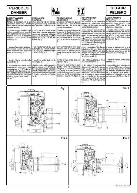
ACCOPPIAMENTO<br />
MECCANICO<br />
Nel caso di accoppiamento di un<br />
generatore serie <strong>TR2</strong> avente<br />
forma costruttiva B3/B9 seguire le<br />
seguenti istruzioni:<br />
-) montare il coperchio anteriore sul<br />
motore fissandolo con le apposite<br />
viti e applicando una coppia di serraggio<br />
di 48±7% se si impiegano<br />
viti M10 o 21±7% Nm nel caso di<br />
viti M8 (fig. 1).<br />
-) bloccare l’alternatore sul coperchio<br />
fissando i quattro dadi M8 sui<br />
tiranti, applicando una coppia di<br />
pari a 16±7% Nm (fig. 2).<br />
-) inserire il tirante centrale nella<br />
sua sede (fig. 3).<br />
-) bloccare il tirante centrale applicando<br />
sul dado M8 una coppia di<br />
serraggio pari a 21±7% Nm; rimontare<br />
le retine di protezione laterali<br />
e la griglia di chiusura posteriore<br />
applicando sulle viti M5 una coppia<br />
di serraggio pari a 3,5±7% Nm<br />
(fig. 4).<br />
MECHANICAL<br />
COUPLING<br />
When coupling with an <strong>TR2</strong> series<br />
generator having a B3 / B9<br />
form, follow the instructions below:<br />
-) mount the front cover on the<br />
motor, fixing it with the appropriate<br />
screws and applying a tightening<br />
torque of 48±7% Nm if using M10<br />
screws or 21±7% Nm for M8<br />
screws (fig. 1).<br />
-) lock the alternator into the cover<br />
by fixing the four M8 nuts onto the<br />
bolts, applying a tightening torque<br />
of 16 ± 7% Nm (fig. 2).<br />
-) insert the central bolt into its<br />
housing (fig. 3).<br />
-) lock the central bolt by applying a<br />
tightening torque of 21±7% Nm to<br />
the M8 nut; reassemble the lateral<br />
protective nets and the rear closing<br />
grid by applying a tightening torque<br />
of 3,5±7% Nm to the M5 screws<br />
(fig. 4).<br />
ACCOUPLEMENT<br />
MECANIQUE<br />
En cas de montage d’un générateur<br />
série <strong>TR2</strong> ayant la forme<br />
constructive B3 / B9, suivre les<br />
instructions suivantes :<br />
-) monter le couvercle avant sur le<br />
moteur en la fixant avec les vis<br />
prévues à cet effet et en appliquant<br />
un couple de serrage de 48±7%<br />
Nm si on utilise des vis M10 ou de<br />
21±7 % Nm en cas de vis M8 (fig.<br />
1).<br />
-) bloquer l’alternateur sur le couvercle<br />
en fixant les quatres écrous<br />
M8 sur les tirants, en appliquant un<br />
couple de serrage de 16 ±7% Nm<br />
(fig. 2).<br />
-) enfiler le tirant central dans son<br />
logement (fig. 3).<br />
-) bloquer le tirant central en appiquant<br />
à l’écrou M8 un couple de<br />
serrage de 21 ± 7% Nm ; remonter<br />
les grilles de protection laterales et<br />
la grille de fermature arriére en appliquat<br />
aux vis M5 un couple desserrage<br />
de 3,5 ±7% Nm (figure 4).<br />
Fig. 1<br />
6<br />
MECHANISCHER<br />
ANSCHLUß<br />
Bei Anschluß einses Generators<br />
der Serie <strong>TR2</strong> mit Bauform B3/B9<br />
müssen die folgenden Answeisungen<br />
befolgt werden:<br />
-) den vorderen Deckel auf den<br />
Motor stzen und ihn mit Hilfe der<br />
entsprechenden Schrauben und<br />
einem Anzugsmoment von 48±<br />
7% festziehen, wenn Schrauben<br />
M10 verwendet werden, oder aber<br />
mit einem Anzugsmoment von<br />
21±7% Nm bei Verwendung von<br />
Schrauben M8 (Abb. 1).<br />
-) den Umwandler auf dem Deckel<br />
befestigen und ihn mit Hilfe der vier<br />
Schraubmuttern M8 an den Zugstangen<br />
befestingen bei Aufbringen<br />
eines Anzugsmoments von<br />
16 ± 7% Nm (Abb. 2).<br />
-) die mittlere Zugstange in ihirem<br />
Sitz einstecken (Abb. 3).<br />
-) die mittlere Zungstange blockieren<br />
und hierfür ein Anzugsmoment<br />
von 21 ± 7% Nm auf die<br />
Schraubmutter aufbringen; die seitlichen<br />
Schutznetze sowie das hintere<br />
Abschlußrost wieder aufsetzen<br />
und hierfür ein Anzugsmoment<br />
von 3,5 ±7% Nm auf die<br />
Schrauben M5 aufbringen (Abb.<br />
4).<br />
GEFAHR<br />
PELIGRO<br />
ACOPLAMIENTO<br />
MECANICO<br />
En el caso de acoplamiento de un<br />
generador serie <strong>TR2</strong> con forma<br />
constructiva B3/B9, siga las instrucciones<br />
siguientes:<br />
-) montar la tapa anterior encima<br />
del motor sujetàndola con sus tornillos<br />
y aplicando un par de torque<br />
de 48±7% Nm si utiliza tornillos<br />
M10, o de 21 ±7% Nm si utiliza<br />
tornillos M8 (fig. 1).<br />
-) sujete el alternador en la tapa<br />
fijando las cuatros tuercas M8 en<br />
los tirantes, aplicando un par de<br />
torque de 16 ±7% Nm (fig. 2).<br />
-) introducir el tirante central en su<br />
lugar (fig. 3).<br />
-) Isujete el tirante central aplicando<br />
en la tuerca M8 un par de torque<br />
de 21±7% Nm; vuelva a montar<br />
las redecillas de protección laterales<br />
y la reijla de cierre posterior,<br />
aplicando a los tornillos M5 un par<br />
de torque de 3,5 ±7% Nm (fig. 4).<br />
Fig. 2<br />
Fig. 3 Fig. 4<br />
<strong>TR2</strong> - Gennaio 2003 rev.03