man_ ER-R definitivo.p65
man_ ER-R definitivo.p65
man_ ER-R definitivo.p65

Create successful ePaper yourself
Turn your PDF publications into a flip-book with our unique Google optimized e-Paper software.
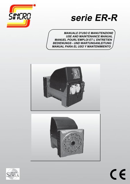
serie <strong>ER</strong>-RMANUALE D'USO E MANUTENZIONEUSE AND MAINTENANCE MANUALMANUEL POURL'EMPLOI ET L`ENTRETIENBEDIENUNGS - UND WARTUNGANLEITUNGMANUAL PARA EL USO Y MANTENIMIENTO
INFORMAZIONI GEN<strong>ER</strong>ALILa <strong>man</strong>utenzione all’alternatore, verifica e sostituzionedi parti deve essere effettuata esclusivamenteda personale qualificato.V<strong>ER</strong>IFICHE PRELIMINARIPrima dell’utilizzo si racco<strong>man</strong>da di esaminarel’alternatore per verificare che non abbia subitodanni durante il trasporto.IMMAGAZZINAGGIOIn caso di inutilizzo prolungato, l’alternatoredeve essere immagazzinato in luogo asciutto ecoperto.Prima della messa in servizio, dopo lunghiperiodi di inattività, controllare la bontà d’isolamentodi tutti gli avvolgimenti; valori accettabilidevono essere maggiori di 2MΩ.In caso contrario si deve procedereall’essiccazione del solo alternatore in forno(60÷70°C).INSTALLAZIONEPrima della messa in funzione, verificare l’esecuzionedei collegamenti, e l’assenza d’impedimentialla rotazione del rotore.Fare attenzione che le aperture per l’aspirazionee espulsione dell’aria non siano ostruite odanneggiate, evitare inoltre che l’alternatoreaspiri l’aria calda espulsa dall’alternatore stessoe/o dal motore.COLLEGAMENTO ELETTRICORispettare le norme di sicurezza vigenti delpaese d’utilizzo.Verificare che i dati di targa siano conformi allecaratteristiche dell’impianto a cui la macchinaverrà collegata.Provvedere al collegamento a terra del gruppo.MANUTENZIONEVerificare che non ci siano anomalie, comevibrazioni - rumori - uscite d’aria ostruite.Controllare il posizionamento e l’usura dellespazzole.SMALTIMENTOL’alternatore è costituito in massima parte daacciaio, rame, alluminio. Al termine dell’utilizzodella macchina rivolgersi ad una agenzia dismaltimento di materiali ferrosi, ed evitare didisperdere parti di alternatore nell’ambiente.GEN<strong>ER</strong>AL INFORMATIONSMaintenance of the alternator, checking andreplacement of parts must be carried out exclusivelyby skilled personnel.PRELIMINARY CHECKSBefore use, it is recommended to examine thealternator to ensure that it has not been damagedduring transport.STORAGEIf the alternator is to remain out of use for a longtime, it must be stored in a dry, covered place.Before starting up, after long periods of inactivity,check that the insulation of all the windingsis in good condition; acceptable values mustbe higher than 2MΩ.Otherwise the alternator alone must be dried inthe oven (60÷70°C).INSTALLATIONBefore starting up, check that the connectionsare correctly made and ensure there are noimpediments to the rotation of the rotor.Take care that the openings for air intake andexpulsion are not blocked or damaged, andensure that the alternator does not take in thehot air expelled by the alternator itself and/orby the motor.ELECTRIC CONNECTIONThe electric connection must be performed inaccordance with the local regulations in force.Make sure that the rating plate data correspondto the specifications of the power mains towhich the machine will be connected. Providethe unit with adequate grounding.MAINTENANCECheck periodically if there are any anomaliessuch as vibrations - noise - obstructions ofinlets and outlets. Check the wear and positionof the brushes.DISMANTLINGMost of the alternator’s parts are made of steel,copper and aluminium. When dis<strong>man</strong>tling themachine contact an authorised scrap irondealer and ensure that no parts of the alternatorare dumped in the environment.INFORMATIONS GEN<strong>ER</strong>ALESLa maintenance de l’alternateur, le contrôle etle remplacement de pièces doivent être effectuésexclusivement par du personnel spécialisé.CONTRÔLES PRÉLIMINAIRESAvant l’utilisation, nous recom<strong>man</strong>dons d’examinerl’alternateur pour vérifier qu’il n’a passubi de dommages durant le transport.STOCKAGEEn cas de non-utilisation prolongée, l’alternateurdoit être stocké dans un endroit sec etcouvert.Avant la mise en service, après de longuespériodes d’inactivité, contrôler l’efficacité del’isolement de tous les enroulements; les valeursacceptables doivent être supérieures à2MΩEn cas contraire, il faut procéder au séchageuniquement de l’alternateur au four (60÷70°C).INSTALLATIONAvant la mise en marche, vérifier toutes lesconnexions et que rien n’empêche la rotationdu rotor.Veiller à ce que les ouvertures pour l’aspirationet l’expulsion de l’air ne soient pas bouchéesou endommagées, éviter en outre que l’alternateuraspire l’air chaud expulsé par l’alternateurproprement dit et/ou par le moteur.CONNEXION ELECTRIQU<strong>ER</strong>especter les normes de sécurité en vigueurdans le pays d’installation. Vérifier la conformitédes données de plaque aux caractéristiquesde l’installation à laquelle la machine serabranchée. Effectuer la liaison du groupe avecla borne de terre.ENTRETIENVérifier périodiquement le bon fonctionnementdu groupe afin de relever d’éventuellesanomalies comme, vibrations - bruits suspects- obstruction des sorties d’air. Vérifier l’usure etla position des balais.MISE AU REBUTL’alternateur est constitué pour la majeure partied’acier, cuivre, aluminium. Quand la machinen’est plus utilisée ou utilisable, s’adresserà une agence pour le recyclage des matériauxferreux et éviter d’abandonner des partiesde l’alternateur dans la nature.ATTENZIONE!Non toccare l’alternatore durante il funzionamentoe subito dopo l’arresto del gruppo,in quanto vi potrebbero essere superficia temperatura elevataLe macchine elettriche rotanti sono macchineche presentano parti pericolose inquanto poste sotto tensione o dotate dimovimento durante il funzionamento, pertanto:- un uso improprio- la rimozione delle protezioni e loscollegamento dei dispositivi di protezione- la carenza di ispezioni e <strong>man</strong>utenzionepossono causare gravi danni a persone ocose.!WARNING!Never touch the alternator during operationor immediately after the stopping of the unitbecause some surface parts might still bevery hot.Electric rotating machines have dangerousparts: when operating they have live androtating components. Therefore:- improper use- the removal of protective covers and thedisconnection of protection devices- inadequate inspection and maintenancecan cause personal injury or propertydamage.! !ATTENTION!Ne pas toucher l’alternateur lors de sonfonctionnement et tout de suite après l’arrêtdu groupe à cause d’un risque detempérature élevée des surfaces.Les machines électriques rotativesprésentent des parties dangereuses car ellessont sous tension ou dotées de mouvement.C’est pourquoi:-Une utilisation non conforme,-La violation des protections et ledébranchement de ces dernières,-Un <strong>man</strong>quement dans les contrôles etl’entretien,peuvent causer de graves dommages auxpersonnes et aux matériels.
ALLGEMEINE INFORMATIONENDie Wartung des Drehstromgenerators sowie dieÜberprüfung und der Austausch von Teilendürfen ausschließlich von Fachpersonalvorgenommen werden.VORB<strong>ER</strong>EITENDE ÜB<strong>ER</strong>PRÜFUNGENVor Benutzung wird dringend empfohlen, denDrehstromgenerator auf eventuelle während desTransports erlittene Beschädigungen zuuntersuchen.LAG<strong>ER</strong>UNGIm Fall einer längeren Nichtbenutzung muß derDrehstromgenerator an einem trockenen undüberdachten Ort gelagert werden.Vor der Inbetriebnahme nach langenNichtbenutzungszeiten den einwandfreienZustand der Isolierung aller Wicklungenkontrollieren; akzeptable Werte müssen höherals 2MW sein.Andernfalls muß eine Trocknung des alleinigenDrehstromgenerators im Ofen (60÷70°C)vorgenommen werden.INSTALLI<strong>ER</strong>UNGVor der Inbetriebnahme die Ausführung derAnschlüsse und das Nichtvorhandensein vonBehinderungen der Rotation des Rotorsüberprüfen.Darauf achten, daß die Öffnungen zum Ansaugenund zum Ausstoß der Luft nicht verstopft oderbeschädigt sind; außerdem vermeiden, daß derDrehstromgenerator die von ihm selbst und/oder vom Motor ausgestoßene warme Luftansaugt.ANSCHLUSSFür den Anschluß die landesgültigenUnfallschutzvorschriften einhalten.Sich überzeugen, daß die Daten des Schildesden Eigenschaften der Anlage entsprechen, andie die Maschine angeschlossen wird.Für den Erdungsanschluß des Aggregatsvorsehen.WARTUNGEs ist wichtig, daß keine Schwingungen,Geräusche, verstopfte Luftauslässe vorhandensind. Verschleiss und Positionieren der Bürstenprüfen.ENTSORGUNGDer Wechselstromgenerator bestehtgrößtenteils aus Stahl, Kupfer und Aluminium.Am Ende der Maschinenverwendung sollte <strong>man</strong>sich an eine Entsorgungsstelle für Eisenwarenwenden, um die Umwelt nicht mit Teilen desWechselstromgenerators zu belasten.ACHTUNGDen Generator während des Betriebs undgleich nach dem Anhalten des Aggregatsnicht anfassen, da die Flächen heiß seinkönnten.Elektrische Rotationmaschinen weisengefährliche Teile auf, die entweder unterSpannung stehen oder während desMaschinenbetriebs drehen.Daher können:- unsachgemäßer Gebrauch;- Entfernen der Schutzverkleidungen undÜberbrücken oder Abklemmen derSchutzeinrichtungen- <strong>man</strong>gelhafte Inspektion oder Wartungzu schweren Personen- oder Sachschädenführen.!INFORMACIONES GEN<strong>ER</strong>ALESTanto el <strong>man</strong>tenimiento del alternador comosu comprobación además de la sustituciónde las piezas, serán realizados única yexclusivamente por personal cualificado.COMPROBACIONES PRELIMINARESSe recomienda examinar el alternador antesde usarlo para comprobar que no se hayaestropeado durante el transporte.ALMACENAJEEn caso de inactividad prolongada del alternador,se almacenará en un lugar seco y cubierto.Después de largos periodos de inactividad yantes de la puesta en servicio, controlar que elaislamiento de todos los bobinados esté enbuenas condiciones; valores aceptables seránlos superiores a 2MΩ.De no ser así, se dispondrá el secado sólo delalternador en el horno (60÷70°C).INSTALACIÓNAntes de poner el alternador en marcha comprobarla ejecución de las conexiones y que nohaya impedimentos para la rotación del rotor.Tener cuidado de que no estén obstruidas niestropeadas las aperturas de aspiración y deexpulsión del aire. Impedir también que elalternador aspire el aire caliente expulsadopor el mismo alternador y/o por el motor.CONEXIÓN ELÉCTRICARespetar las normas de seguridad vigentes enel país de utilización.Verificar que los datos de placa correspondena las características de la red en el lugar deinstalación de la máquina.Efectuar la puesta a tierra del grupo.MANTENIMIENTOComprobar que no hay anomalías comovibraciones, ruidos y salidas de aire obstruidas.Controlàr deterioro y colocaciòn de lasescobillas.DEMOLICIONEl alternador está fabricado en casi todas suspartes en acero, cobre y aluminio. Al final dela vida del aparato, dirigirse a una empresaencargada de la eliminación de materialesferrosos, evitando la liberación de algunaspartes del alternador al medio ambiente.!ATENCIÓNNunca tocar el alternador durante elfuncionamiento o inmediatamente despuésde la parada del grupo, dado que haysuperficies de temperatura elevadaLas màquinas eléctricas giratorias sonmáquinas que tienen piezas peligrosas yaque están bajo tensión o se mueven duranteel funcionamiento. Por lo tanto:- el uso inadecuado- la remoción de las protecciones y ladesconexión de los dispositivos deseguridad- la falta de chequeo y <strong>man</strong>tenimiento,pueden causar danõs graves a personas ocosas.
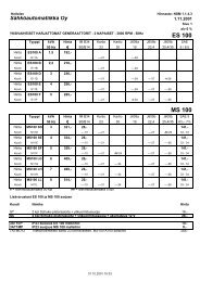
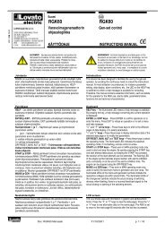
ISTRUZIONI P<strong>ER</strong> IL MONTAGGIO(FORMA IM B35)ATTENZIONE: prima del montaggioverificare che le sedi coniche di accoppiamento(sia dell'alternatore che del motore)siano regolari e ben pulite.1) Fissare lo scudo copriventola (1) almotore (dopo averlo tolto dall'alternatore).2) Applicare il tirante (2) per il fissaggioassiale del rotore avvitandolo sulla sporgenzadell'albero motore.3) Fissare l'alternatore completo (statoree rotore assieme) allo scudo usando i 4tiranti M8 (3) e i dadi autobloccanti M8 (4)4) Verificare che le sedi coniche del rotoree del motore siano in contatto colpendoassialmente il rotore con un mazzuolodi plastica.5) Bloccare assialmente il rotore avvitandoil dado autobloccante M8 (4) sultirante (2).Attenzione: prima di applicare il dado osservareche parte della porzione filettata deltirante entri nel rotore permettendo cosí unsicuro bloccaggio.6) Montare il tappo (7).Fissare le due griglie di protezione (6).7) Supportare il gruppo con adeguatiantivibranti (5) curando il corretto allineamentotra motore e alternatoreASSEMBLY INSTRUCTIONS(IM B35 COUPLING)ON: before assembly make sure that theconical coupling housings for both thealternator and the motor are in order andclean.1) Clamp the fan shield (1) on the drivemotor (after removing it from the alternator).2) Apply the tie rod (2) for the axialclamping of the rotor, and screw it on thedrive shaft.3) Fasten the complete alternator (statorand rotor together) to its shield, using the4 tie rods M8 (3) and the M8 (4) self-lockingnuts.4) Check that the cone seats of rotor andmotor are engaged by tapping the head ofthe rotor with a plastic mallet.5) Axially lock the rotor in place bytightening the M8 (4) self-locking nut on thetie rod (2).Caution: before applying the nut, make surethat the threaded part of the rod partiallyenters the rotor in order to obtain tight locking.6) Fasten the tap (7).Fasten the protection grid (6).7) Support the unit on appropriatevibration dampeners (5) taking care on thealignment between engine and alternator.INSTRUCTIONS POUR LE MONTAGE(FORME IM B35)ATTENTION: Avant d’effectuer le montage,vérifier que les sièges coniquesd’accouplement (de l’alternateur comme dumoteur) sont en ordre et bien nettoyés.1) Fixer le bouclier couvre-rotor (1) aumoteur (après l’avoir désolidarisé del’alternateur).2) Mettre en place la tige (2) de fixationaxiale du rotor en la vissant à l’ergot del’arbre moteur.3) Fixer l’alternateur (complet avec statoret rotor) au bouclier au moyen de 4 tiges M8(3) et les écrous autobloquants M8 (4).4) Vérifier que les sièges coniques durotor et du moteur sont en contact enfrappant axialement le rotor avec un mailleten plastique.5) Bloquer l’axe du rotor en serrant l’écrouautobloquant M8 (4) sur la tige centrale (2).Attention: Avant de mettre en place l’écrou,contrôler que la partie filetée de la tige estinsérée dans le rotor permettant ainsi unblocage sûr.6) Fixer le bouchon (7).Fixer lex deux grilles de protection (6).7) Soutenir le groupe avec desamortisseur de vibrations (5) en faisantattention que le moteur et l'alternateur soientdans le même axe.REGOLAZIONE DELLA VELOCITA’La frequenza e la tensione dipendono direttamentedalla velocità di rotazione, la qualedeve quindi ri<strong>man</strong>ere il più possibile costanteal variare del carico.Considerando che il sistema di regolazionedella velocità dei motori di trascinamentopresenta in generale una leggera caduta digiri tra vuoto e carico, si racco<strong>man</strong>da diregolare la velocità a vuoto circa il 3÷4%superiore alla velocità nominale.SPEED ADJUSTMENTFrequency and voltage depend directly onthe speed of revolution, which must thereforeremain as constant as possible when theload varies.The speed adjustment system of the drivemotors usually gives a slight drop inrevolutions between no load and load, sowhen the no load speed is being adjusted, itis best to set it at approx. 3-4% above therated speed.RÉGLAGE DE LA VITESSELa fréquence et la tension dépendentdirectement de la vitesse de rotation qui doitrester le plus possible constante quand lacharge varie.Vu que le système de réglage de la vitessedes moteurs d’entraînement présente engénéral une légère baisse du nombre detours à vide ou en charge, il est conseillé derégler la vitesse à vide à une valeursupérieure de 3 à 4 % par rapport à lavitesse nominale.
MONTAGEANLEITUNG(IMB35 ANSCHLUSS)ACHTUNG: Sich vor dem Einbau überzeugen,daß die kegelförmigen Kupplungssitze(sowohl des Generators als auch desMotors) regelmässig und sauber ist.1) Das Flügelrad-Abdeckschild (1) amMotor befestigen (nachdem es vomGenerator entfernt wurde).2) Die Spannstange (2) für die Längsbefestigungdes Rotors anbringen und sieauf der Vorkragung der Motorwellefestschrauben.3) Den vollständigen Generator (Statorund Rotor zusammen) mit den 4 SpannstangenM8 (3) und den selbstsperrendenM8 Muttern (4) am Kasten befestigen.4) Prüfen, dass die konischen Sitze desRotors und des Motors in Kontakt sind,indem mit einem Plastikhammer axial aufden Rotor geschlagen wird.5) Den Rotor axial blockieren, und dieselbstsperrende M8 Mutter (4) an dieSpannstange (2) anzuschrauben.Achtung: bevor die Mutter angebracht wird,beatchten, dass ein Teil des Gewindes derSpannstange in den Rotor eintritt unddadurch eine sichere Blockierungermöglicht.6) Den Stopfen (7) montieren.Den zwei Schutzgitter (6) montieren.7) Das Aggregat mit geeignetenSchwingungsdämpfern (5) stützen, dabeidie korrekte Ausrichtung zwischen Motorund Generator beachten.INSTRUCCIONES DE MONTAJE(ACOPLAMIENTO IMB35)AVISO: Antes del montaje cerciorarse deque los asientos cónicos de acoplamiento(tanto del alternador como del motor) sonregulares y limpios.1) Fijar el escudo cubreventilador (1) almotor (después de haberlo sacado delalternador).2) Aplicar el tirante (2) para la fijaciónaxial del rotor enroscándolo en la partesaliente del eje motor.3) Fijar el alternador completo (estator yrotor juntos) en el escudo utilizando los 4tirantes M8 (3) y las tuercas de seguridadM8 (4).4) Verificar que los asientos cónicos delrotor y del motor estén en contacto, y paraello se golpea axialmente el rotor con unmartillo de plástico.5) Bloquear axialmente el rotorenroscando la tuerca autobloqueante M8(4) en el tirante (2).Aviso: para realizar un bloqueo seguro,antes de aplicar la tuerca hacer entrar unaparte de la pieza fileteada del tirante en elrotor.6) Montar el tapòn (7).Fijar las dos rejillas de protecciòn (6)7) Sostener el grupo con antivibradores(5) adecuados cuitando de que el motor y elalternador se encuentren correctamentealineados.EINSTELLUNG D<strong>ER</strong> GESCHWINDIGKEITFrequenz und Spannung hängen direkt vonder Drehgeschwindigkeit ab, die daher beiLastveränderung so konstant wie möglichbleiben muss.Unter Berücksichtigung, dass dasRegulierungssystem der Geschwindigkeitder Mitnehmermotoren im allgemeineneinen leichten Drehzahlabfall zwischenLeerlauf und Last aufweist, wird empfohlen,die Leerlaufgeschwindigkeit auf ca. 3÷4%höher als die Nenngeschwindigkeiteinzustellen.REGULACION DE LA VELOCIDADTanto la frecuencia como la tensióndependen directamente de la velocidad derotación, lo que supone que éstaper<strong>man</strong>ecerá lo más posible constante alvariar la carga.Dado que el sistema de regulación de lavelocidad de los motores de arrastre presentauna ligera disminución de revolucionesentre vacío y cargado, se recomienda regularla velocidad en vacío alrededor del 3÷4%superior a la velocidad nominal.
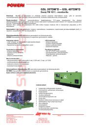
REGOLATORE ELETTRONICO (AVR-L)L’ AVR è un dispositivo adatto a <strong>man</strong>tenerecostante (+\-2%) la tensione al variare delcarico e dei parametri della macchina.L’AVR necessita di un collegamento, dettosensing; di un’alimentazione apposita(AUX); di un’uscita verso il rotore (+/-).L’uso di carichi distorcenti può alterare ilvalore di tensione in quanto l’AVR non effettuauna misura di valore efficace (RMS),quindi può peggiorare la precisione di tensioneal variare del carico.Una apposita tasca ricavata sul bordo dellascheda contiene un fusibile di scorta (fusibiletipo 32x6,3 3,15A rapido).REGOLAZIONE DELL’AVR-LÈ possibile modificare la tensione di uscitaagendo sul potenziometro Volt. Con il gruppoin moto alla velocità nominale, regolarefino ad ottenere il valore cercato.Il trimmer di taratura della tensione permetteuna regolazione da 130V a 90V con collegamentoparallelo e da 260Vmax a180Vmin con collegamento serie.Qualora l’alternatore <strong>man</strong>ifestasse oscillazionidi tensione, ruotare il trimer della stabilitàST.IMPORTANTE! Non regolare l’AVR inmodo da far erogare all’alternatore unatensione al di fuori del campo di +/-5%rispetto a quella di targa per non surriscaldarel’alternatore stesso. Non lasciarei morsetti del sensing scollegati.ELECTRONIC REGULATOR (AVR-L)The AVR is used for keeping a constantvoltage (+\-2%) as the load and machineparameters vary.The AVR requires a so-called sensingconnection; a power supply from a specificcircuit (AUX); an output to the rotor (+/-).The use of distorting loads can alter thevoltage since the AVR does not performtrue-RMS and voltage precision cantherefore be lost as the load varies.There is a special pocket built into the edgeof the board to contain a spare fuse (rapidfuse type 32x6.3 3,15A ).AVR-L ADJUSTMENTThe output voltage can be changed byadjusting the Volt potentiometer. While thegenerating set is running at nominal speed,adjust until the required voltage is obtained.The voltage calibration trimmer providesadjustment from 130V to 90V whenconnected in parallel and from 260Vmax to180Vmin when connected in series.If the alternator should produce voltagefluctuations, turn the stability trimmer ST.CAUTION! Do not set the AVR to makethe alternator supply a voltage range ofover +/-5% nominal to avoid overheatingthe alternator. Do not leave the sensingterminals disconnected.RÉGULATEUR ÉLECTRONIQUE (AVR-L)L’AVR est un dispositif servant à maintenirune tension constante (+\-2%) quand lacharge et les paramètres de la machinechangent.L’AVR à besoin d’un branchement, ditsensing, d’une alimentation spécifique(AUX), d’une sortie vers le rotor (+/-).L’emploi de charges défor<strong>man</strong>tes peutaltérer la valeur de tension dans la mesureoù l’AVR n’effectue pas une mesure devaleur efficace (RMS), et peut donc empirerla précision de tension à la variation de lacharge.Une poche spéciale sur le bord de la cartecontient un fusible de réserve (fusible type32x6,3 3,15A rapide).RÉGLAGE DE L’AVR-LIl est possible de modifier la tension desortie en agissant sur le potentiomètre Volt.Avec le groupe en mouvement à la vitessenominale, régler jusqu’à ce que l’onobtienne la valeur désirée.Le trimmer de réglage de la tension permetun réglage de 130 V à 90 V avec connexionparallèle et de 260 V max. à 180 V min.avec connexion en série.Si l’alternateur <strong>man</strong>ifeste des oscillationsde tension, agir sur le trimmer de la stabilitéST.IMPORTANT ! Ne pas régler l’AVR de<strong>man</strong>ière à ce que l’alternateur produiseune tension hors champ de +/-5% parrapport à celle de la plaque pour ne pasle surchauffer. Ne pas laisser les bornesdu sensing déconnectées.voltstab
ELEKTRONISCH<strong>ER</strong> REGL<strong>ER</strong> (AVR-L)Beim AVR handelt es sich um eineVorrichtung, die die Spannung beiVeränderung der Ladung und der Parameterder Maschine konstant halten soll (+\-2%).Der AVR benötigt einen als “Sensing”bezeichneten Anschluss; eineentsprechende Speisung (AUX); einenAusgang zum Rotor hin (+/-).Der Gebrauch von verdrehenden Lastenkann den Spannungswert verändern, da derAVR keine wirksame Wertmessungvornimmt (RMS); er kann daher dieSpannungspräzision bei Veränderung derLadung verschlechtern.Eine entsprechende am Rand der Karteausgearbeitete Einstecktasche enthält eineErsatzsicherung (Flinksicherung Typ 32x6,33,15A).EINSTELLUNG DES AVR-LDie Ausgangsspannung kann durchEinwirkung auf das Volt-Potentiometerverändert werden. Bei mitNenngeschwindigkeit laufendem Aggregatregeln, bis der gewünschte Wert erzieltwurde.Der Trimmer zur Eichung der Spannungermöglicht eine Einstellung von 130V bis90V bei Parallelschaltung, und von260Vmax. bis 180Vmin. beiSerienschaltung.Falls der DrehstromgeneratorSpannungsschwankungen aufweisen sollte,den Trimmer der Stabilität ST drehen.WICHTIG! Den AVR nicht so einstellen,dass der Drehstromgenerator eine ummehr als +/-5% außerhalb des Bereichsliegende Spannung im Vergleich zur aufdem Typenschild genannten Spannungliefert, um den Drehstromgeneratorselbst nicht zu überhitzen. Die Sensing-Klemmen nicht abgetrennt lassen.REGULADOR ELECTRÓNICO (AVR-L)El AVR es un dispositivo destinado a<strong>man</strong>tener constante (+\-2%) la tensión alvariar la carga y los parámetros de lamáquina, y necesita una conexión llamadasensing, así como una alimentaciónadecuada (AUX) y una salida hacia el rotor(+/-).El uso de cargas distorsionales puedealterar el valor de tensión, dado que el AVRno mide el valor de modo eficaz (RMS) y,por tanto, puede empeorar la precisión dela tensión al variar la carga.El fusible de repuesto (tipo 32x6,3 3,15Arápido) está guardado en el bolsillopertinente obtenido en el borde de la tarjeta.CÓMO SE REGULA EL AVR-LLa tensión de salida se modifica a travésdel potenciómetro Volt. Con el grupo enfuncionamiento a velocidad nominal,regular hasta alcanzar el valor deseado.Con el trimmer de calibrado de la tensión,se consigue una regulación de 130V a 90Vcon conexión paralela y de 260Vmáx a180Vmín con conexión serial.De <strong>man</strong>ifestar el alternador oscilaciones detensión, girar el trimmer de la estabilidadST.IMPORTANTE! No regular el AVR deforma que el alternador suministre unatensión fuera del campo de +/-5%respecto a la indicada en la placa decaracterísticas, con el fin de nosobrecalentar el alternador. No dejardesconectados los bornes del sensing.
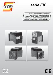
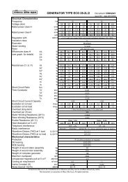
Schemi elettriciWiring diagrams Schema electrique Schaltpläne Esquemas eléctricosColori-colourscouleur-farbecolorBianco: white blancweiss blancoBlu: blue bleublau azulGrigio: grey grisgrau grisCOLOUR(*)Nero: black noireschwarz negroMarrone: brownmarron braunmarrònRosso: red rougerot rojoArancione: orangeorange orangeanaranjadoGiallo: yellow jaunegelb amarilloViola: violet violetteviolett violeta12VdcOPTIONALCOLORE (*) TENSIONE FREQUENZACOLOR UR(*) VOLTAGE FREQUENCYGRIGIO 115V/230V 50 HzGIALLO 120V/240V 50 HzARANCIONE 110V/220V 60 HzVIOLA 120V/240V 60 HzV/2(115V)PARALLELS<strong>ER</strong>IESV(230V)V/2(115V)Resistenza degli avvolgimenti (20°C)Winding resistances (20°C)Résistance des bobinages (20°C)Widerstand der Wicklung (20°C)Resistencias de los bobinados (20°C)Tipo Statore Ausiliario Carica batt. RotoreType Stator Auxiliary Batt. charger RotorType Stator Excitation Char. Batt. RotorTyp Stator Erregung Ladegerät RotorTipo kVA Estator Excitaciòn Carga baterìa Rotor(R1) (R2) (R3) (R4)Dati eccitazioneExcitation dataDonnées d`excitationKompoundierungsdatenDatos excitacióna vuotoa pieno caricono loadfull loada vide en charge nom.bei leerlaufbei vollasten vacìo con plena cargaΩ Ω Ω Ω V dc A dc V dc A dc50HZ - 3000 r.p.m. - 230V 50HZ - 3000 r.p.m. - 230V<strong>ER</strong>2SCA 3 2.1 5,1 0,16 12,2 11,40 0,80 49,0 3,8<strong>ER</strong>2CAA 4.2 1,28 4,1 0,13 13,7 12,50 0,90 54,0 4<strong>ER</strong>2CBA 4.8 1,20 2,6 0.13 14,4 13,20 0,92 58,5 4,160HZ - 3600 r.p.m. - 240V 60HZ - 3600 r.p.m. - 240V<strong>ER</strong>2SCA 3.7 1,5 3,65 0,13 12,2 11,40 0,80 49,0 3,8<strong>ER</strong>2CAA 5.2 0,92 2,93 0,11 13,7 12,50 0,90 54,0 4<strong>ER</strong>2CBA 6 0,85 1,85 0,11 14,4 13,20 0,92 58,5 4,1
Restituzione macchine in riparazioneReturning machines repairedRetour marchandises pour reparationRückgabe der maschinen zur reparaturDevolución máquinas en reparaciónLo scopo della presente schedaè assicurare al Cliente unvalido ed efficiente servizio diassistenza. Questa schedadovrà essere consegnata all'utilizzatorefinale da parte delvenditore locale.PROCEDURANel caso di guasti o anomaliedi funzionamento delle macchineSincro, il Cliente è invitatoad interpellare il nostro"Servizio Assistenza" telefonandoallo 0445-450500.Se, dopo tale contatto, risultassenecessaria la restituzionedel prodotto, il nostro"Servizio Assistenza" forniràal Cliente un numero di "RientroMateriale Autorizzato"(RMA), che dovrà essere riportatosia sui documenti diaccompagnamento del materialeche nella presente Schedadi Riparazione.Prodotti resi senza aver seguitola descritta procedura eprivi della scheda di riparazione,verranno respinti al mittentedal magazzino accettazione.Per l'eventuale concessionedella garanzia è indispensabileche la Sincro sia contattataesclusivamente dal proprioCliente. Richieste di riparazioneprovenienti direttamentedall'utilizzatore finale sarannoin ogni caso considerateNON in garanzia.Prima di procedere a riparazioniverrà comunicato un preventivoe si attenderà l'autorizzazioneda parte del ClienteSCHEDA DIRIPARAZIONELa scheda di riparazione deveessere compilata per ogni prodottoed inclusa nell'imballo direstituzione. L'accuratezzanella compilazione renderà ilnostro intervento rapido e risolutivo.SPEDIZIONELa merce resa viaggia esclusivamentea spese e a rischiodel Cliente indipendentementedalla concessione dell'interventoin garanzia.Curare che le macchine sianoin ordine, pulite e che l'olio dieventuali moltiplicatori di girisia stato vuotato.Si racco<strong>man</strong>da di restituire ilmateriale entro un imballo adeguatocurando di proteggere ilprodotto dagli urti.The scope of this card is toensure the client with a validand efficient assistanceservice. This card must begiven to the purchaser by thelocal dealer.PROCEDUREWhenever any Sincromachine malfunctions, theclient is invited to contact our“Assistance Service” bycalling ++39 0445 450500. Ifthe decision is made to returnthe product, we will provideyou with an “AuthorizedMaterial Return” (RMA)number that must be includedboth in the deliverydocuments that accompanythe material and this RepairCard. Products that havebeen returned withoutfollowing the procedureabove and without a RepairCard will be returned tosender.In order to obtain coverageunder the warranty, Sincromust be contactedexclusively by its authorizeddealer. Requests for repairsreceived directly from finaluser clients will be consideredoutside the terms of warrantycoverage. Prior to performingrepair, an estimate will beprovided and authorizationmust be received from theauthorized dealer beforeproceeding with the repair.REPAIR CARDA repair card must becompiled for every productand enclosed in thepackaged product sent forrepair. Providing accurateand complete information inthe Repair Card will help usrepair the product faster andbetter.SHIPMENTAll products to be repairedare shipped at the risk andexpense of the clientregardless of whetherwarranty coverage will beclaimed or not. The clientmust make sure that themachines sent for repair arein good order, clean, and thatthe oil in the overgear systemhas been drained. Werecommend returning theproducts in adequatepackaging that ensuresprotection against impact.Le but de la présente ficheest d’assurer au client unservice après-vente rapideet efficace. Cette fiche devraêtre communiqué à l’utilisateurfinal de la part durevendeur agréé.PROCEDUREEn cas de pannes oud’anomalies de fonctionnementdes machinesSincro, le client est invité àcontacter notre “ServiceAssistance” en téléphonantau ++39 0445 450500. Si à lasuite de ce contact, larestitution du produit s’avèrenécessaire, notre “ServiceAssistance” communiqueraau client un numéro pour le“Retour Matériel Autorisé”(RMA) qui devra être reportésur le document d’accompagnementdu matériel commesur la présente Fichetechnique de réparation.Les produits rendus sansavoir suivi la procéduredécrite et privés de la Fichetechnique de réparationseront retournés àl’envoyeur. Pour uneéventuelle concession degarantie il est indispensableque la Sincro soit contactédirectement par le revendeuragréé. Les de<strong>man</strong>des deréparation effectuées parl’utilisateur final serontconsidérées comme étanthors garantie. Toutede<strong>man</strong>de de réparation feral’objet d’un devis.FICHE TECHNIQUE D<strong>ER</strong>EPARATIONLa fiche technique deréparation doit être rempliepour chacun des produits etjointe à la marchandiserestituée. La clarté desdonnées fournies permettraune intervention rapide etdécisive.EXPEDITIONLes frais d’expédition sont àla charge du client et cela,indépendamment du fait quela marchandise soit encoresous garantie. Faire en sorteque les machines soient aucomplet, nettoyées et quel’huile des éventuelsmultiplicateurs de tours ait étéévacuée. Il est conseilléd’expédier la machine dansun emballage adapté etantichoc.Zweck dieser Karte ist, demKunden einen guten und wirksamenKundendienst zu gewährleisten.Diese Karte solldem Endbenutzer vom lokalenVerkäufer übergeben werden.V<strong>ER</strong>FAHRENBei Schäden oder Betriebsstörungender Sincro-Maschinen,ist der Kunde gebeten, unseren"Kundendienst" unter der Nummer++39 0445 450500 anzurufen.Falls nach dieser Kontaktaufnahmeeine Rückgabe des Produktserforderlich sein sollte,gibt unser "Kundendienst" demKunden eine "Nummer für dieRückgabe von autorisiertemMaterial" (RMA), die sowohl indie Begleitunterlagen des Materialsals auch in dieseReparaturkarte einzutragen ist.Produkte, die ohne o.g. Vorgangund ohne Reparaturkartezurückgegeben werden, werdennicht akzeptiert und vonder Annahmestelle an den Absenderzurückgegeben.Füreine eventuelle Garantiegewährungist es erforderlich,daß die Fa. Sincro ausschließlichvom Kunden selbst kontaktiertwird. Vom Endbenutzergemachte Reparaturanfragenwerden in jedem Fall als NICHTunter Garantie stehende Fällebearbeitet.Vor der Reparaturausführungwird ein Kostenvoranschlag mitgeteiltund eine Genehmigungseitens des Kunden abgewartet.REPARATURKARTEDie Reparaturkarten müsen fürjedes Produkt ausgefüllt werdenund in der Rückgabeverpackungeingeschlossen sein.Die sorgfältige Ausfüllung ermöglicheinen unserseitigen raschenund problemlösendenEingriff.V<strong>ER</strong>SANDUnabhängig von der Gewährungdes Garantieeingriffs, reistdie zurückgegebene Ware ausschließlichauf Kosten und Risikendes Kunden. Sich überzeugen,daß die Maschinen in Ordnungund sauber sind und daßdas Öl eventueller Drehzahlübersetzerausgeleert wurde.Es wird empfohlen, das Materialin einer entsprechendgeeigneten Verpackungzurückzugeben, um dasProdukt vor Stößen zuschützen.Esta ficha se remite al Clientecon la finalidad de garantizarleun servicio de postventaválido y eficiente. El revendedorlocal tiene que suministrarlaal usuario final.PROCEDIMIENTOEn caso de averías o anomalíasde funcionamiento de lasmáquinas Sincro, aconsejamosal Cliente que se pongaen contacto con el ServicioPostventa lla<strong>man</strong>do el número++39 0445 450500. Si acontinuación de la llamadafuera necesario devolver elproducto, el Servicio dePostventa suministrará alCliente un número de “RegresoMaterial Autorizado”(RMA), que deberá encontrarsetanto en los documentosde expedición del material,como en la presente Ficha deReparación.Productos devueltos sin haberefectuado el procedimientodescrito anteriormente y losque no tengan la ficha de reparación,se rechazarán alCliente del Almacén de aceptación.Por lo que respecta a la posibleconcesión de la garantía,es preciso que Sincro secontacte únicamente por elCliente; la petición de reparacionesdirectamente por partedel usuario final han deconsiderarse NON en garantía.Antes de proceder a lareparación se comunicará unpresupuesto al Cliente y seesperará la autorización delmismo.FICHA DE REPARACIÓNLa ficha de reparación debecompletarse para cada productoe incluirse en el embalajede devolución. La esmeradacompletación de la fichapermitirá una reparación rápiday eficiente.ENVÍOLos gastos de transporte correnpor cuenta y riesgo delCliente, independientementede la concesión de la intervenciónen garantía.Cerciorarse de que las máquinasestán limpias y en buenestado, y que el aceite de losposibles multiplicadores devueltas ha sido vaciado. Aconsejamosdevolver el materialen un embalaje que permitaprotegerlo durante el transporte.
Scheda di riparazione:Repair card:Fiche technique de réparation:Reparaturkarte:Ficha de reparación:RMA:Tecnico contattato:Technician contacted:Technicien contacté:Kontaktierter Techniker:Técnico contactado:DATA:Descrizione del prodotto:Description of product:Description du produit:Produktbezeichnung:Descripción del producto:Modello:Model:Modèle:Modell:Modelo:Matricola:Serial number:N° de série:Kennummer:Matrícula:Ditta:Company:Entreprise:Firma:Empresa:Tel/Fax:Persona da contattare:Contact person:Contact:Ansprechpartner:Persona a contactar:Barrare la casella corrispondente:Put an "X" in the corresponding box:Barrer la case correspondante:Das entsprechende Kästchen ankreuzen:Rellenar la casilla correspondiente:Motivo della restituzione:Reason for return::Motif(s) de la restitution:Begründung d. Rückgabe:Motivo de la devolución:Riparazione:Repair:Réparation:Reparatur:Reparación:Manutenzione:Maintenance:Entretien:Wartung:Mantenimiento:Assenza di tensione:No voltage:Absence de tension:Spannungs<strong>man</strong>gel:Falta de tensión:Tensione bassa:Low voltage:Tension insuffisante:NiederspannungTensión baja:Problemi meccanici:Mechanical problems:Problèmes mécaniques:Mechanische Probleme:Problemas mecánicos:Note:Notes:Remarques:Anmerkungen:Notas:IDENTIFICAZIONE CLIENTE - CLIENT IDENTIFICATION - DONNEES D’IDENTIFICATION CLIENT -KUNDENBEZEICHNUNG - IDENTIFICACIÓN DEL CLIENTEProblemi sul quadretto elettrico:Electrical control panel problems:Problème au niveau des circuits électriques:Probleme am Schaltbrett:Problemas en el cuadro eléctrico:Tensione alta:High voltage:Surtension:Hochspannung:Tensión alta:SINCRO s.r.l. - Via Tezze, 3 36073 Cereda di Cornedo Vicentino Vicenza - Italy -ph. +39 0445 450500 - fax. +39 0445 446222
GARANZIAWARRANTYGARANTIEGARANTIEGARANTÍALa Sincro s.r.l garantisce aipropri clienti gli alternatori esaldatrici prodotti al suointerno per un periodo di 12mesi a decorrere dalla datadi consegna. Si precisa chedetta garanzia è rivolta ai soliclienti della Sincro ai qualidirettamente risponde. LaSincro non riconoscedirettamente la garanzia adalcun soggetto che, pur inpossesso dei suoi prodotti,non li abbia da essaacquistati direttamente.Nel caso dei distributoriufficiali della Sincro nelmondo, la garanzia vieneestesa a 18 mesi dalla datadi consegna.Entro i suddetti termini laSincro si impegna a forniregratuitamente pezzi diricambio di quelle parti che,a giudizio della Sincro o diun suo rappresentanteautorizzato, presentinodifetti di fabbricazione o dimateriale oppure, a suogiudizio, ad effettuarne lariparazione direttamente oper mezzo di officineautorizzate senzaassumersi alcun onere peril trasporto.Ri<strong>man</strong>e comunque esclusaqualsiasi altra forma diresponsabilità oobbligazione per altrespese, danni e perditedirette o indirette derivantidall’uso o dalla impossibilitàd’uso dei prodotti, sia totaleche parziale.La riparazione o la forniturasostitutiva non prolungherà,né rinnoverà la durata delperiodo di garanzia.La garanzia decadrà:qualora si <strong>man</strong>ifestasseroinconvenienti o guasti dovutiad imperizia, utilizzo oltre ailimiti delle prestazioninominali, se il prodottoavesse subito modifiche ose dovesse ritornaredisassemblato o con dati ditarga alterati o <strong>man</strong>omessi.Per la richiesta di garanzia iclienti dovranno attenersialla procedura descrittanella scheda gialla allegataal <strong>man</strong>uale d’uso e<strong>man</strong>utenzione che, per laresa del materiale, dovràaccompagnare ogniprodotto.Sincro S.r.l. guarantees theown alternators and weldersfor a period of 12 monthsstarting from the invoiceissue date. We confirm thatwarranty is directed only toSincro customers to whichwe respond. Sincro does notgrant warranty to those whohave not directly purchasedthe product from the factory,in spite of the possession ofit.Within the above mentionedterms, Sincro commits itselfto supply free of chargethose spare parts that,according to its judgment orto the one of an authorizedrepresentative, appear with<strong>man</strong>ufacturing or materialdefects or, always to itsjudgment, to directly orthrough an authorized centrecarry out the repairingwithout undertakingtransport costs.We anyhow exclude formsof responsibility or obligationfor other costs, damages anddirect or indirect loss causedby the total or partial usageor impossible usage of theproducts.The repairing or thesubstitution will not extendor renew the warrantyduration.Warranty will not be granted:whenever break-downs orproblems may appearbecause of lack ofexperience, usage over thenominal perfor<strong>man</strong>ces, if theproduct had been modifiedor should return incomplete,disassembled or withmodified nameplate data.For the warranty request, thecustomers must follow theprocedure described on theyellow card included in theuser’s <strong>man</strong>ual, which issupplied with each product.Sincro s.r.l garantit à sesclients les alternateurs et lesmachines à souderproduites par ses soins pourune période de 12 mois àcompter de la date delivraison. Nous précisonsque cette garantie estaccordée uniquement auxclients de Sincro auxquelselle répond directement.Sincro ne reconnaîtdirectement la garantie àaucun sujet qui, tout enpossédant l’un de sesproduits, ne le lui a pasacheté directement.Dans le cas desdistributeurs officiels deSincro dans le monde, lagarantie est étendue à 18mois à compter de la datede livraison.Dans les périodes susdites,Sincro s’engage à fournirgratuitement les pièces derechange des parties qui, del’avis de Sincro ou de l’un deses représentants agréés,présentent des défauts defabrication ou de matériauou bien, selon sonjugement, elle s’engage àen effectuer la réparationdirectement ou par le biaisd’ateliers agréés sansprendre à sa charge aucunfrais pour le transport.Toute autre forme deresponsabilité ou obligationpour d’autres frais,dommages ou pertesdirectes et indirectesdérivant de l’utilisation ou del’impossibilité d’utilisationdes produits, tant partielleque totale, reste exclue.La réparation ou leremplacement du produit neprolongeront ni nerenouvelleront la période degarantie.La garantie ne sera pasapplicable en cas de pannesou d’inconvénients dus àl’inexpérience, à l’utilisationau-delà des limites desperfor<strong>man</strong>ces nominales, sile produit a subi desmodifications ou s’il estretourné démonté ou avecdes données de plaquealtérées ou modifiées.Pour la de<strong>man</strong>de degarantie, les clients devrontsuivre la procédure décritedans la fiche jaune jointeau <strong>man</strong>uel d’instructions etde maintenance qui devraaccompagner chaqueproduit en cas de retour dematériel.Die Firma Sincro s.r.l gewährtihren Kunden eine Garantievon 12 Monaten Laufzeit abdem Auslieferungsdatum aufdie in ihrem Betriebh e r g e s t e l l t e nDrehstromgeneratoren undSchweißmaschinen. Es wirdpräzisiert, dass dieseGarantie ausschließlich fürdie Kunden der Firma Sincro,denen gegenüber sie direkthaftet, bestimmt ist. Die FirmaSincro erkennt keine direkteGarantie gegenüberPersonen/Firmen an, die,obwohl sie im Besitz ihrerProdukte sind, diese nichtdirekt von ihr gekauft haben.Wenn es sich um offizielleVertriebshändler der FirmaSincro im Ausland handelt,wird die Garantie auf 18Monate ab demAuslieferungsdatumausgedehnt.Die Firma Sincro verpflichtetsich, innerhalb der obengenannten Fristen kostenlosErsatzteile für jene Teile zuliefern, die ihrem eigenenUrteil oder dem eines von ihrautorisierten Vertretersgemäß Fabrikations- oderMaterialmängel aufweisen,oder, wenn sie dies für richtighält, die Reparatur direkt odermittels autorisierterWerkstätten auszuführen,wobei sie keinerleiTransportaufwendungenübernimmt.Ausgeschlossen bleibt jedochjegliche sonstige Form derHaftung oder Verpflichtung inBezug auf anderweitigeKosten, Schäden und direkteoder indirekte Verluste, diesich aus dem Gebrauch oderaus der Unmöglichkeit desGebrauchs der Produkteableiten, sei es in vollemUmfang oder teilweise.Die Reparatur oderErsatzlieferung bewirkt wedereine Verlängerung noch eineErneuerung der Laufzeit derGarantie.Die Garantie verfällt, wennProbleme oder Störungenauftreten, die durchunsachgemäßen Gebrauchentstehen, bei Einsatz überdie Nennleistungsgrenzenhinaus, wenn am ProduktAbänderungen vorgenommenwurden oder wenn es inzerlegtem Zustand oder mitveränderten bzw.<strong>man</strong>ipulierten Daten desTypenschilds zurückgesandtwerden sollte.Zur Beantragung vonGarantieleistungen müssendie Kunden sich an denVerfahrensablauf halten, derim gelben Datenblatt, das derBedienungs- undWartungsanleitung beigefügtist und das beiMaterialrücksendung jedesProdukt begleiten muss,beschrieben ist.Sincro s.r.l garantiza a susclientes los alternadores ysoldadoras de sufabricación por un periodode 12 meses a partir de lafecha de entrega. Seespecifica que Sincroreconoce exclusivamente lagarantía que ampara solo asus propios clientes, antelos que se hacedirectamente responsable.Sincro no reconocedirectamente la garantía aningún sujeto que, a pesarde estar en posesión de susproductos, no los hayaadquirido directamente deella.Respecto de losdistribuidores oficiales deSincro en el mundo, lagarantía se amplía a 18meses a partir de la fechade entrega.Dentro de los términosestablecidos Sincro seobliga a proporcionargratuitamente piezas derecambio de las partes que,según el juicio de laempresa Sincro o de unrepresentante suyoautorizado, tengandefectos de fabricación odel material, o bien, segúnsu juicio, a efectuar lareparación directamente opor medio de talleresautorizados, sin correr conningún gasto por eltransporte.De cualquier modo, quedaexcluida toda otra forma deresponsabilidad uobligación por otros gastos,daños y pérdidas directas oindirectas que deriven deluso o de la imposibilidad deutilizar en todo o en partelos productos.La reparación o elsuministro sustitutivo noprolongará ni renovará laduración del periodo degarantía.La garantía se invalidará enel caso de que sem a n i f e s t a r a ninconvenientes o averíasdebidos a incompetencia oa un uso que supere loslímites de las prestacionesnominales, así como en elcaso de modificacionesaportadas al producto o dedevolución con el artículodesensamblado o con lascaracterísticas nominalesalteradas o <strong>man</strong>ipuladas.Para solicitar la garantía,los clientes deberánatenerse al procedimientodescrito en la ficha amarillaque se adjunta con el<strong>man</strong>ual de uso y<strong>man</strong>tenimiento y quedeberá acompañar elmaterial en el caso dedevolución.
Centri di assistenza autorizzati italiani - Italian Sincro service centersValle d‘AostaOfficina Elettromeccanica Menegolo G. &C. S.n.c.Loc. Plan Felinaz, 7311020 Charvensod (Aosta)Tel. 0165 / 44144Fax 0165 / 232539LombardiaPardini GuidoVia Ugo Bassi, 927058 Voghera ( PV)Ph. 0383 367290Fax 0383 367347VenetoSINCRO S.r.l.Via Tezze, 336073 Cereda di Cornedo Vic.no(Vicenza)Tel. 0445 450500Fax 0445 446222e-mail: service.sincro@sogagroup.comEmilia RomagnaF.lli Cesari S.n.c.Via dei Caligari, 440129 BolognaTel. 051 322221Fax. 051 4189595Puglia - Basilicata - MoliseEuromotor B.G.Str. Prov. Mariotto, 9 e 13/E70038 Terlizzi - (Bari)Tel. 080 3514204Fax 080 3512941Campania - CalabriaCandileno Domenico & Figli S.n.c.Via Garibaldi, 2280026 Casoria - (Napoli)Tel. 081 7596424Fax 081 5842662SardegnaElettro Meccanica dei F.lli Brai di G. & A.S.n.c.Via Ginevra Zona Industriale Nord09170 OristanoTel. 0783 / 357008Fax 0783 / 359939SiciliaDenaro G.B. & C. S.n.c.Via G. Matteotti, 38297017 Vittoria - (Ragusa)Tel. 0932 981686Fax 0932 987520Elettromeccanica Oddo SebastianoVia Asmara98076 S. Agata Militello - (Messina)Tel. 0941 701171Fax 0941 723066Officina elettromeccanica GalloFrancescoVia A. Ligabue (ex E. 88) , 1493012 Gela (CL)Ph. and Fax 0933 919596Centri di assistenza autorizzati nel mondo - Worldwide Sincro service centersAlbaniaCema Sh. Pk.Rr. Kavajes Ish Kombinati TekstilFabrika Ngjyrosjes - TiranaPh. +355 4352562Fax +355 4352562E-mail: cema@icc-al.orgAustralia - New Zealand - PacificIslandsSincro Australia Pty Ltd.Po box 177, 2/22 Tepko Rd. TerreyHillsNSW AUSTRALIAPh. 0061 294500993Fax 0061 294500663E-mail: sales@sincro.com.auCanadaCanimex Inc.285, St. GeorgesJ2C 4H3 Drummondville - Quebec -CANADAPh. 001 819 4771335Fax 001 819 4770306GreciaExanVia Kapetan Agra, 6257009 Kalohori Salonicco - GRECIAPh. 0030 2310753860Fax 0030 2310753928E-mail: exansa@acn.grHolland - Belgium - LuxembourgMeijco Elektro HollandPastoor Vav Laakstraat, 566663 CB LENT HOLLANDPh. 0031 243220085Fax 0031 243233197e-mail: meyco.elektro@worldonline.nlIsraelShatal Engineering (1992) Ltd.3 Nahal Poleg St.PO Box: 32YAVNE81100 ISRAELPh. 00972 8 9320202Fax 00972 8 9428763E-mail: shatal@shatal.comPolandScangerUl. Gen. Sikorskiego 21/2362 - 031 Lubon K / Poznania -POLANDPh. 0048 618139478Fax 0048 618139479RussiaPerpetuum Mobile Ltd.Moscow, ul. Smolnaya 24a office 1609Ph. 007- 095 - 9673307Fax 007- 095 - 9673308E-mail: sales@p-mobile.ruSouth AfricaPower Equipment Sales & ServicesRep.14 Fraaiuitsig St. GlentanaPo box 1897 George WP 6530 - RSAPh. 0027 448790680Fax 0027 448791837SpainRentnostrum S.L.Apartado 218E 03180 Torrevieja AlicanteSPAINPh. 0034 96 5705656Fax. 0034 96 5705500E-Mail: arianic@teleline.esUnited Arab EmiratesAikah EstablishmentAirport Rd. - P.o. Box 5804 - DUBAIPh. 00971 4 3478005Fax 00971 4 3478006UKSogagroup UK Ltd.P.O. Box 823Guilford, SurreyGU3 1ZLPh. 0044 148 3813227Fax 0044 8452803122E-Mail :franciscradock@sogagroup.co.ukU.S.A.Getec Incorporated624, Harris Road 12734 Ferndale - NY- U.S.A.Ph. 001 845 2920800Fax. 001 845 2920830E-mail: postmaster@getec.com
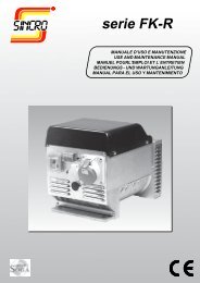
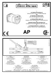
Disegno esploso Exploded view Vue eclatee TeilmontagezeichnungDespiece301334522217 20351162 229465393218291Parti di ricambio Spare parts list Pieces detachees ErsatzteillisteN.RIF CODICESINCRO31Partes de recambioDESCRIZIONE DESCRIPTION DESCRIPTION BESCHREIBUNG DESCRIPCIÓN1(*) 4061011023 Scudo anteriore "E" IMB35 J609A Front shield "E" IMB35 J609A Flasque antérieur "E" IMB35 J609A Vorderer Kasten "E" IMB35 J609A Escudo anterior "E" IMB35 J609A4061011031 Scudo anteriore "E" IMB35 J609B Front shield "E" IMB35 J609B Flasque antérieur "E" IMB35 J609B Vorderer Kasten "E" IMB35 J609b Escudo anterior "E" IMB35 J609B4061011022 Scudo anteriore "E" IMB35 c.23-c.30 Front shield "E" IMB35 c.23-c.30 Flasque antérieur "E" IMB35 c.23-c.30 Vorderer Kasten "E" IMB35 c.23-c.30 Escudo anterior "E" IMB35 c.23-c.304061011011 Scudo anteriore "E" IMB34 (B3/B14) Front shield "E" IMB34 (B3/B14) Flasque antérieur "E" IMB34 (B3/B14) Vorderer Kasten "E" IMB34 (B3/B14) Escudo anterior "E" IMB34 (B3/B14)2(*) 266062001 Griglia anteriore IP21 Front grid IP21 Grille de protection antérieure IP21 Vorderes Gitter IP21 Rejilla anterior IP21266042001 Griglia anteriore IP23 Front grid IP23 Grille de protection antérieure IP23 Vorderes Gitter IP23 Rejilla anterior IP233 1750016205 Cuscinetto 6205 2RS C3 Bearing - 6205 2RS C3 Roulement - 6205 2RS C3 Lager 6205 2RS C3 Cojinete 6205 2RS C34 266083001 Ventola (con foro d.30) Fan (with hole d.30) Ventilateur (avec trou d.30) Lüfterrad mit Loch d. 30 Ventilador agujero d.305(*) 17600… Tirante albero (dimensioni-accoppiam.?) Shaft stay bolt (dimensions-coupling ?) Tige centrale (dimensions-accouplem. ?) Spannstange (Kupplungsabmessung ?) Tirante àrbol (dimens. - acoplamiento ?)6(*) R531226---- Rotore <strong>ER</strong>-R (Accoppiamento ?) (1) Rotor <strong>ER</strong>-R (Coupling ?) (1) Rotor <strong>ER</strong>-R (Accouplement ?) (1) Rotor <strong>ER</strong>-R (Kupplung ?) (1) Rotor <strong>ER</strong>-R (Acoplamiento ?) (1)9(*) 661205… Carcassa + Stat. <strong>ER</strong>-R Housing + Stat. <strong>ER</strong>-R Carcasse + Stat. <strong>ER</strong>-R Gehäuse + Stat. <strong>ER</strong>-R Carcasa + Estat. <strong>ER</strong>-R11 1750016005 Cuscinetto 6005 C3 Bearing - 6005 C3 Roulement - 6005 C3 Lager 6005 C3 Cojinete 6005 C317 30010210 Filtro EMC EMC filter Filtre EMC EMC-Filter Filtro EMC18 3065014216071 Collettore 42x16x07 Slip ring 42x16x07 Collecteur 42x16x07 Kollektor 42x16x07 Colector 42x16x0720 406601050810 Portaspazzole+spazzole Brush-holder + brushes Porte-balais+balais Bürstenhalter+Bürsten Portaescobillas+escobillas22 266061004 Cuffia EK cieca Blind EK end cover Couvercle post. aspiration EK sans trous EK Schutzkasten Tapa EK ciega posterior29 266064007 Tappo EK Tap (EK) Bouchon (EK) Stopfen EK Tapòn EK30 266024008 Coperchio <strong>ER</strong> nero <strong>ER</strong> black top cover Couvercle supérieur <strong>ER</strong> noir Gitterhaltedeckel <strong>ER</strong>schwarz Tapa negra (<strong>ER</strong>)31 300005 KIT: da IMB35 J609B a IMB34 (B3/B14) KIT: from IMB35 J609B to IMB34 (B3/B14) KIT: de IMB35 J609B à IMB34 (B3/B14) KIT: von IMB35 J609B bis IMB34 (B3/B14) KIT: da IMB35 J609B a IMB34 (B3/B14)32(*) 7022… Quadretto EK monofase (vedi...) EK single-phase panel (see...) Tableau monophasè EK (voir...) Schaltbrett EK einphasiger (siehe . . . ) Cuadro EK monofasico (Véase...)33(*) 7065… Quadretto <strong>ER</strong> (vedi...) <strong>ER</strong> panel (see...) Tableau <strong>ER</strong> (voir...) Schaltbrett <strong>ER</strong> (siehe . . . ) Cuadro <strong>ER</strong> (Véase...)35(*) 3008015 Scheda elettronica AVR-L AVR-L electronic board Elektronische Karte AVR-L Carte électronique AVR-L Tarjeta electrònica AVR-L3008016 Scheda elettronica AVR-L CE AVR-L CE electronic board Elektronische Karte AVR-L CE Carte électronique AVR-LCE Tarjeta electrònica AVR-L CE46 176006030 Tirante M8x30 Stay bolt - M8x30 Tige M8x30 Spannstange M8x30 Tirante M8x3052 30430203 Fusibile 32x6,3 2,5A F Fuse 32x6,3 2,5A F Sicherung 32x6,3 2,5A F Fusible 32x6,3 2,5A F Fusible 32x6,3 2,5A F(1) Comprende il particolare 4+11+18 (1) 4+11+18 item is included (1) Comprend la pièce 4+11+18 (1)Teil 4+11+18 inbegriffen (1) Incluye el particular 4+11+18(*) Includere nella richiesta di pezzi di ricambio la descrizione dell'oggetto, il codice, il numero di matricola e le caratteristiche della macchina (rilevabili dalla targhetta).(*) When ordering spare parts, please indicate the alternator code-number and machine serial number and characteristics (they are available on the label)(*) Nous vous prions d’indiquer, dans vos com<strong>man</strong>des de pièces de rechange, la description de la pièce, le numéro de code et de série et les caractéristiques de la machine(*) In den Ersatzteilanfrage sind die Gegenstandbeschreibung, die Materialnummer, die Kennummer und die Eigenschaften der Maschine (vom Schild zu entnehmen) anzugeben.(*) Solicitar las piezas de recambio siempre indicando la descripción del objeto, el código, el número de matrícula y las características de la máquina (descritas en la placa de identificación).
INCONVENIENTI CAUSE RIMEDIOIl generatore non si eccita. 1) Macchina smagnetizzata. 1) Applicare una tensione di 6÷12V ai morsetti delrotore (cavetti nero e rosso) rispettando la polarità.2) Guasto negli avvolgimenti. 2) Controllare le resistenze degli avvolgimenti come databella.3) Velocità ridotta 3) Controllare i giri e portarli al valore nominale.4) Regolatore difettoso. 4) Controllare e sostituire.5) Fusibile guasto 5) Controllare il fusibile e sostituireTensione a vuoto bassa. 1) Velocità troppo bassa. 1) Riportare la velocità del gruppo al valore nominale.2) Regolatore fuori taratura. 2) Agire sul potenziometro VOLT .3) Avvolgimenti avariati. 3) Controllare le resistenze degli avvolgimenti come databella.4) Regolatore difettoso. 4) Controllare e sostituire.Tensione a vuoto troppo alta. 1) Sensing non collegato. 1) Collegare i cavetti del sensing.2) Regolatore fuori taratura. 2) Agire sul potenziometro VOLT .3) Regolatore difettoso. 3) Controllare e sostituire.Tensione corretta a vuoto, 1) Possibile sovraccarico. 1) Controllare la corrente di carico.troppo bassa a carico. 2) Il motore rallenta. 2) Controllare dimensionamento motore e carico.3) Regolatore difettoso. 3) Controllare e sostituire.Tensione instabile. 1) Contatti incerti. 1) Controllare le connessioni.2) Regolatore fuori taratura. 2) Agire sul potenziometro STAB.3) Irregolarità di rotazione. 3) Verificare l’uniformità di rotazione.Surriscaldamento della 1) Aperture di ventilazione 1) Smontare e pulire le cuffie di aspirazione edmacchina. parzialmente ostruite. espulsione aria.2) Possibile sovraccarico. 2) Controllare la corrente di carico.Macchina rumorosa. 1) Cuscinetti avariati. 1) Controllare e sostituire.2) Accoppiamento difettoso. 2) Verificare e riparare.PROBLEM CAUSE REMEDYGenerator will not excite. 1) Machine demagnetised. 1) Apply a 6-12V voltage to the rotor terminals(black & red wires) according to polarity.2) Fault in windings. 2) Check resistance of windings (see table)3) Speed too low 3) Check rpm's and restore nominal speed.4) Faulty regulator. 4) Check and replace.5) Fuse blown 5) Check fuse and replaceNo load voltage too low. 1) Speed too low. 1) Restore nominal speed of set.2) Regulator out of calibration. 2) Adjust VOLT potentiometer.3) Fault in windings. 3) Check resistance of windings (see table)4) Faulty regulator. 4) Check and replace.No load voltage too high. 1) Sensing not connected. 1) Wire up sensing.2) Regulator out of calibration. 2) Adjust VOLT potentiometer.3) Faulty regulator. 3) Check and replace.No load voltage correct, 1) Possible overload. 1) Check load current.but load voltage too low. 2) Motor drags. 2) Check motor and load are sized correctly.3) Faulty regulator. 3) Check and replace.Unstable voltage. 1) Poor contacts. 1) Check contacts.2) Regulator out of calibration. 2) Adjust STAB potentiometer.3) Irregular rotation. 3) Check for constant rotation.Machine overheats 1) Air vents clogged 1) Remove and clean air inlet and outlet hoods2) Possible overload. 2) Check load currentMachine noisy. 1) Worn out bearings. 1) Check and replace.2) Faulty coupling. 2) Check and repair.
INCONVÉNIENTS CAUSES REMÈDELe générateur ne s’excite pas. 1) Machine démagnétisée. 1) Appliquer une tension de 6÷12 V aux bornes du rotor(câbles noir et rouge) en respectant la polarité.2) Panne dans les enroulements. 2) Contrôler les résistances des enroulements selon letableau.3) Vitesse réduite. 3) Contrôler les tours et les porter à la valeur nominale.4) Régulateur défectueux. 4) Contrôler et remplacer.5) Fusible en panne. 5) Contrôler et remplacer le fusible.Tension à vide basse. 1) Vitesse trop basse. 1) Reporter la vitesse du groupe à la valeur nominale.2) Régulateur mal étalonné. 2) Agir sur le potentiomètre VOLT .3) Avarie des enroulements. 3) Contrôler les résistances des enroulements selon letableau.4) Régulateur défectueux. 4) Contrôler et remplacer.Tension à vide trop élevée. 1) Sensing non connecté. 1) Connecter les câbles du sensing.2) Régulateur mal étalonné. 2) Agir sur le potentiomètre VOLT .3) Régulateur défectueux. 3) Contrôler et remplacer.Tension correcte à vide, 1) Surcharge possible. 1) Contrôler le courant de charge.trop basse en charge. 2) Le moteur ralentit. 2) Contrôler le dimensionnement du moteur et de la charge.3) Régulateur défectueux. 3) Contrôler et remplacer.Tension instable. 1) Contacts incertains. 1) Contrôler les connexions.2) Régulateur mal étalonné. 2) Agir sur le potentiomètre STAB.3) Irrégularité de rotation. 3) Vérifier l’uniformité de rotation.Surchauffe de la machine. 1) Ouvertures de ventilation 1) Démonter et nettoyer les coiffes d’aspiration etpartiellement bouchées. d’expulsion de l’air.2) Surcharge possible. 2) Contrôler le courant de charge.Machine bruyante. 1) Avarie des roulements. 1) Contrôler et remplacer.2) Accouplement défectueux. 2) Vérifier et réparer.PROBLEME URSACHEN ABHILFEDer Generator erregt sich nicht. 1) Maschine entmagnetisiert 1) Eine Spannung von 6÷12V an den Klemmen desRotors anwenden (schwarzes und rotes Kabel),unter Einhaltung der Polung.2) Defekt an den Wicklungen 2) Die Widerstände der Wicklungen gemäß Tabelle kontrollieren.3) reduzierte Geschwindigkeit 3) Die Umdrehungen kontrollieren und auf den Nennwert bringen.4) Regler schadhaft 4) Kontrollieren und auswechseln.5) Sicherung defekt 5) Die Sicherung kontrollieren und auswechseln.Spannung im Leerzustand niedrig 1) Geschwindigkeit zu niedrig 1) Die Geschwindigkeit des Aggregats auf den Nennwert bringen.2) Regler außerhalb der Eichung 2) Auf das Potentiometer VOLT einwirken.3) Wicklungen beschädigt 3) Die Widerstände der Wicklungen gemäß Tabelle kontrollieren.4) Regler schadhaft 4) Kontrollieren und auswechseln.Spannung im Leerzustand zu hoch 1) Sensing nicht angeschlossen 1) Die Sensing-Kabel anschließen.2) Regler außerhalb der Eichung 2) Auf das Potentiometer VOLT einwirken.3) Regler schadhaft 3) Kontrollieren und auswechseln.Spannung im Leerzustand korrekt, 1) Mögliche Überlastung 1) Den Ladestrom kontrollieren.im Ladezustand zu niedrig 2) Der Motor verlangsamt. 2) Die Dimensionierung des Motors und die Ladung kontrollieren.3) Regler schadhaft. 3) Kontrollieren und auswechseln.Spannung nicht stabil 1) Unsichere Kontakte 1) Die Anschlüsse kontrollieren.2) Regler außerhalb der Eichung 2) Auf das Potentiometer STAB einwirken.3) Rotationsunregelmäßigkeit 3) Die Gleichmäßigkeit der Rotation überprüfen.Überhitzung der Maschine 1) Belüftungsöffnungen 1) Die Abdeckungen der Luftansaug- und Luftausstoßöffnungenteilweise verstopftdemontieren und reinigen.2) Mögliche Überlastung. 2) Den Ladestrom kontrollieren.Die Maschine erzeugt Lärm. 1) Lager beschädigt 1) Kontrollieren und auswechseln.2) Kupplung schadhaft 2) Überprüfen und reparieren.
INCONVENIENTES CAUSAS REMEDIOEl generador no se excita. 1) Máquina desmagnetizada. 1) Aplicar una tensión de 6÷12V a los bornes delrotor (cables negro y rojo) respetando la polaridad.2) Avería de los devanados. 2) Controlar las resistencias de los devanados segúnla tabla.3) Velocidad reducida. 3) Controlar las revoluciones y configurarlas según valor nominal.4) Regulador defectuoso. 4) Controlar y sustituir.5) Fusible averiado. 5) Controlar el fusible y sustituirTensión en vacío baja. 1) Velocidad demasiado baja. 1) Volver a poner la velocidad del grupo según el valor nominal.2) Regulador fuera calibrado. 2) Ajustar con el potenciómetro VOLT.3) Devanados averiados. 3) Controlar las resistencias de los devanados según laTabla.4) Regulador defectuoso. 4) Controlar y sustituir.Tensión en vacío demasiado alta. 1) Sensing no conectado. 1) Conectar los cables del sensing.2) Regulador fuera calibrado. 2) Ajustar con el potenciómetro VOLT.3) Regulador defectuoso. 3) Controlar y sustituir.Tensión correcta en vacío, 1) Posible sobrecarga. 1) Controlar la corriente de carga.demasiado baja con carga. 2) El motor decelera. 2) Controlar el dimensionamiento del motor y la carga.3) Regulador defectuoso. 3) Controlar y sustituir.Tensión inestable. 1) Contactos inciertos. 1) Controlar las conexiones.2) Regulador fuera calibrado. 2) Ajustar con el potenciómetro STAB.3) Irregularidad de rotación. 3) Verificar la uniformidad de rotación.Sobrecalentamiento de la 1) Aperturas de ventilación 1) Desmontar y limpiar las capuchas de aspiración ymáquina. parcialmente obstruidas. expulsión del aire.2) Posible sobrecarga. 2) Controlar la corriente de carga.La máquina hace demasiado 1) Cojinetes averiados. 1) Controlar y sustituir.ruido. 2) Acoplamiento defectuoso. 2) Verificar y reparar.
DICHIARAZIONE DI CONFORMITA'La societàCONFORMITY C<strong>ER</strong>TIFICATEThe companyDECLARATION DE CONFORMITE'La sociétéSINCRO S.R.L.Via Tezze,3 36073 Cereda di Cornedo Vicentino - Vicenza ITALYdichiara sotto la propria responsabilità chegli alternatorideclares under its own responsibility thatthe alternators:déclare sous sa propre responsabilité queles alternateursserie <strong>ER</strong>-Rserie <strong>ER</strong>-Rsérie <strong>ER</strong>-Rsono costruiti e collaudati in accordo allenorme di seguito indicate:have been <strong>man</strong>ufactured and tested in compliancewith the following standardssont construits et testés dans le respect desnormes indiquées ci-après:CEI EN 60034-1 (CEI 2-3 - NF 51.100 - VDE 0530 - BS 4999-5000)CEI EN 60204-1 (CEI 44-5)EN 292-1, 292-2IEC 34.1, 34.5e risultano conformi:1) ai requisiti generali di sicurezza stabilitidalla Direttiva Bassa Tensione del 19 Febbraio1973 (73/23 CEE), recepita in Italiacon la legge n°791 del 18 Ottobre 1977.2) alla Direttiva 89/336 CEE (mod. dalla93/68 CEE) riguardante il ravvicinamentodelle legislazioni degli stati membri in materiadi compatibilità elettromagnetica.La verifica di compatibilità è stata condottain base alle seguenti norme:and thereby conform to:1) all General Safety Requirements as providedby the EEC Low Voltage Directivedated 19 February 1973 (73/23 EEC).2) all principal safety requirement specifiedby the Committee for Adapting MemberStates Legal Regulation on ElectromagneticCompatibility (89/336 EEC, 93/68 EEC).The following standards were used to evaluatethe electromagnetic compatibility:et sont conformes:1) Aux conditions générales de sécuritéétablies par la Directive relative à la bassetension du 19 Février 1973 (73/23 CEE),adoptée par l’Italie par promulgation de laloi n°791 du 18 Octobre 1977.2) A la Directive 89/336 CEE (et modificationsuccessive 93/68 CEE) concernantl’harmonisation des législations des étatsmembres en matière de comptabilitéélectromagnétique.La vérification de compatibilité a étéeffectuée conformément aux normessuivantes:EN 55011 (CEI 110-6)EN 50081-1 (CEI 110-7)EN 50082-1 (CEI 110-8)Gli alternatori oggetto della presente dichiarazionesono da intendersi come componenti;pertanto vige il divieto di messa inservizio prima che le macchine in cui sarannoincorporati siano dichiarate conformialle direttive riguardanti la sicurezza (98/37/CE) e la compatibilità elettromagnetica.The alternators covered by this certificatemust be considered as components andtherefore prohibited from being placed inoperation before the machine in which theywill be used has been certificated for conformityto safety directives (98/37/CE) andfor electromagnetic compatibility.Les alternateurs objets de la présentedéclaration doivent être considérés commeétant des composants. En conséquence, lamise en service de ces derniers est interdite,avant la mise en conformité des machinesauxquelles ils seront incorporés. Les ditesmachines devront être déclarées conformesaux directives regardant la sécurité (98/37/CE) et la compatibilité électromagnétique.Cereda di Cornedo, li 03/2004Sincro s.r.l.L’amministratore delegatoThe Managing DirectorL’Administrateur DéléguéFlavio Pistollato
KONFORMITÄTS<strong>ER</strong>KLÄRUNGDie FirmaDECLARACIÓN DE CONFORMIDADLa sociedadSINCRO S.R.L.Via Tezze,3 36073 Cereda di Cornedo Vicentino - Vicenza ITALYerklärt unter der eigenen Verantwortung,daß der Bau und die Abnahme der GeneratorenBaureihe <strong>ER</strong>-Rdeclara bajo la propia responsabilidad quelos alternadoresserie <strong>ER</strong>-Rden nachstehenden Vorschriften entspricht:han sido fabricados y probados siguiendola normativa que se detalla a continuación:CEI EN 60034-1 (CEI 2-3 - NF 51.100 - VDE 0530 - BS 4999-5000)CEI EN 60204-1(CEI 44-5)EN 292-1, 292-2IEC 34.1, 34. 5darüberhinaus erfüllen sie:1) die allgemeinen Sicherheitsanforderungender Richtlinie für Niederspannungvom 19 Februar 1973 (73/23 CEE), inItalien mit dem Gesetz Nr. 791 vom 18 Oktober1977 aufgenommen.2) die Richtlinie 89/336CEE (Mod. der 93/68 CEE) bezüglich der Annäherung derGesetzgebungen der Mitgliedsstaaten inSachen elektromagnetischer Kompatibilität.Die Kompatibilitätsprüfung wurde mit Zugrundelegungfolgender Normen ausgeführt:y cumplen:1) las prescripciones que sobre seguridadquedan definidas en la Norma sobre la BajaTensión del 19 de Febrero del 1973 (73/23CEE) introducida en Italia con la ley n° 791del 18 de Octubre del 1977.2) la Norma 89/336 CEE (y sucesiva modificación93/68 CEE) sobre la compatibilidadelctromagnética.La prueba de compatibilidad se ha realizadoen base a las siguientes normas:EN 55011 (CEI 110-6)EN 50081-1 (CEI 110-7)EN 50082-1 (CEI 110-8)Die Generatoren, Gegenstand dieser Erklärung,sind als Komponenten zu verstehen;daher ist ihre Inbetriebnahùe verboten, bevornicht die Maschinen, in die sie integriertwerden, mit den Richtlinien bezüglich Sicherheit(98/37/CE) und elektrischerKompatibiolität für konform erklärt werden.Los alternadores objeto de la presente declaraciónhan de entenderse como componentes;por lo tanto se prohibe su puesta enservicio antes de que las máquinas a lascuales se acoplarán no se declaren conformesa las normas sobre seguridad (98/37/CE) y sobre compatibilidad elctromagnética.Cereda di Cornedo, li 03/2004Sincro s.r.l.Delegierter des VerwaltungsratsEl Administrador DelegadoFlavio Pistollato
Cod 0900233 - 03/04La SINCRO si riserva di apportare modifiche senza preavviso.The <strong>man</strong>ufacturer reserves the right to modify features without notice.Les valeurs peuvent subir des variations sans préavis.Die Werte können ohne Vorankündigung Änderungen unterzogen werden.La Sincro se reserva el derecho de aportar las modificaciones sin preaviso.SINCRO S.R.L. - Via Tezze, 3 - 36073 Cereda di Cornedo Vicentino Vicenza - Italy ph. +39 0445 450500 - fax +39 0445 446222e-mail : sales.sincro@sogagroup.com ; e-mail : service.sincro@sogagroup.comweb : www.sogagroup.com