man_ ER-R definitivo.p65
man_ ER-R definitivo.p65
man_ ER-R definitivo.p65

You also want an ePaper? Increase the reach of your titles
YUMPU automatically turns print PDFs into web optimized ePapers that Google loves.
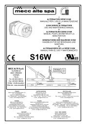
ISTRUZIONI P<strong>ER</strong> IL MONTAGGIO(FORMA IM B35)ATTENZIONE: prima del montaggioverificare che le sedi coniche di accoppiamento(sia dell'alternatore che del motore)siano regolari e ben pulite.1) Fissare lo scudo copriventola (1) almotore (dopo averlo tolto dall'alternatore).2) Applicare il tirante (2) per il fissaggioassiale del rotore avvitandolo sulla sporgenzadell'albero motore.3) Fissare l'alternatore completo (statoree rotore assieme) allo scudo usando i 4tiranti M8 (3) e i dadi autobloccanti M8 (4)4) Verificare che le sedi coniche del rotoree del motore siano in contatto colpendoassialmente il rotore con un mazzuolodi plastica.5) Bloccare assialmente il rotore avvitandoil dado autobloccante M8 (4) sultirante (2).Attenzione: prima di applicare il dado osservareche parte della porzione filettata deltirante entri nel rotore permettendo cosí unsicuro bloccaggio.6) Montare il tappo (7).Fissare le due griglie di protezione (6).7) Supportare il gruppo con adeguatiantivibranti (5) curando il corretto allineamentotra motore e alternatoreASSEMBLY INSTRUCTIONS(IM B35 COUPLING)ON: before assembly make sure that theconical coupling housings for both thealternator and the motor are in order andclean.1) Clamp the fan shield (1) on the drivemotor (after removing it from the alternator).2) Apply the tie rod (2) for the axialclamping of the rotor, and screw it on thedrive shaft.3) Fasten the complete alternator (statorand rotor together) to its shield, using the4 tie rods M8 (3) and the M8 (4) self-lockingnuts.4) Check that the cone seats of rotor andmotor are engaged by tapping the head ofthe rotor with a plastic mallet.5) Axially lock the rotor in place bytightening the M8 (4) self-locking nut on thetie rod (2).Caution: before applying the nut, make surethat the threaded part of the rod partiallyenters the rotor in order to obtain tight locking.6) Fasten the tap (7).Fasten the protection grid (6).7) Support the unit on appropriatevibration dampeners (5) taking care on thealignment between engine and alternator.INSTRUCTIONS POUR LE MONTAGE(FORME IM B35)ATTENTION: Avant d’effectuer le montage,vérifier que les sièges coniquesd’accouplement (de l’alternateur comme dumoteur) sont en ordre et bien nettoyés.1) Fixer le bouclier couvre-rotor (1) aumoteur (après l’avoir désolidarisé del’alternateur).2) Mettre en place la tige (2) de fixationaxiale du rotor en la vissant à l’ergot del’arbre moteur.3) Fixer l’alternateur (complet avec statoret rotor) au bouclier au moyen de 4 tiges M8(3) et les écrous autobloquants M8 (4).4) Vérifier que les sièges coniques durotor et du moteur sont en contact enfrappant axialement le rotor avec un mailleten plastique.5) Bloquer l’axe du rotor en serrant l’écrouautobloquant M8 (4) sur la tige centrale (2).Attention: Avant de mettre en place l’écrou,contrôler que la partie filetée de la tige estinsérée dans le rotor permettant ainsi unblocage sûr.6) Fixer le bouchon (7).Fixer lex deux grilles de protection (6).7) Soutenir le groupe avec desamortisseur de vibrations (5) en faisantattention que le moteur et l'alternateur soientdans le même axe.REGOLAZIONE DELLA VELOCITA’La frequenza e la tensione dipendono direttamentedalla velocità di rotazione, la qualedeve quindi ri<strong>man</strong>ere il più possibile costanteal variare del carico.Considerando che il sistema di regolazionedella velocità dei motori di trascinamentopresenta in generale una leggera caduta digiri tra vuoto e carico, si racco<strong>man</strong>da diregolare la velocità a vuoto circa il 3÷4%superiore alla velocità nominale.SPEED ADJUSTMENTFrequency and voltage depend directly onthe speed of revolution, which must thereforeremain as constant as possible when theload varies.The speed adjustment system of the drivemotors usually gives a slight drop inrevolutions between no load and load, sowhen the no load speed is being adjusted, itis best to set it at approx. 3-4% above therated speed.RÉGLAGE DE LA VITESSELa fréquence et la tension dépendentdirectement de la vitesse de rotation qui doitrester le plus possible constante quand lacharge varie.Vu que le système de réglage de la vitessedes moteurs d’entraînement présente engénéral une légère baisse du nombre detours à vide ou en charge, il est conseillé derégler la vitesse à vide à une valeursupérieure de 3 à 4 % par rapport à lavitesse nominale.