N137923 man planer D26676-B5.indd - Service - DeWALT
N137923 man planer D26676-B5.indd - Service - DeWALT
N137923 man planer D26676-B5.indd - Service - DeWALT

You also want an ePaper? Increase the reach of your titles
YUMPU automatically turns print PDFs into web optimized ePapers that Google loves.
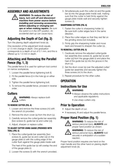
ENGLISHASSEMBLY AND ADJUSTMENTSWARNING: To reduce the risk ofinjury, turn unit off and disconnectmachine from power source beforeinstalling and removing accessories,before adjusting or changing setupsor when making repairs. Be surethe switch is in the OFF position. Anaccidental start-up can cause injury.Adjusting the Depth of Cut (fig. 2)Turn the planing depth adjustment knob (d).One revolution of the adjustment knob equalsa 1.5 mm change in depth. One graduationcorresponds to a depth of cut of 0.1 mm, and this isoffered up to 1.0 mm in depth.Attaching and Removing the ParallelFence (fig. 1, 3)The parallel fence (l) is used for optimum tool controlon narrow workpieces.1. Loosen the parallel fence tightening bolt (f).2. Fit the parallel fence (l) in the hole (g) on eitherside.3. Tighten the parallel fence tightening bolt.4. To remove the parallel fence, proceed in reverseorder.CuttersWARNING: Always replace bothcutters.TO REMOVE CUTTER (FIG. 4)1. Loosen and remove the three screws (m) withthe wrench (n) provided.2. Remove the drum cover (q) from the drum (u).3. Carefully remove the cutter/guide bar assembly[two screws (t), guide bar (s) and cutter (o)].4. Adjust, sharpen or replace cutter.TO ADJUST CUTTER USING GAUGE (PROVIDED WITHTOOL) (FIG. 5)1. Place the cutter/guide bar assembly [twoscrews (t), guide bar (s) and cutter (o)] on thegauge plate (r) with the cutting edge of thecutter flush against the gauge plate inside wall.The heel of the guide bar (s) will overlap the endof the gauge plate (r).2. Loosen the screws (t) with the wrench provided.3. Simultaneously push the cutter (o) and the guidebar (s) into the gauge plate inside wall, makingsure that the cutter is held fi rmly against thegauge plate inside wall and securely tightenscrews (t).SHARPENING CUTTERS (FIG. 6)1. Fasten the cutter to sharpening holder (v).Be sure both cutter edges face in the samedirection.2. Place the cutter edges so that they rest flat onthe grinding stone (not included).3. Firmly grip the sharpening holder and moveback and forward to sharpen the cutter (o).TO REINSTALL CUTTER (FIG. 5)1. Cautiously remove the adjusted cutter/guidebar assembly [two screws (t), guide bar (s) andcutter (o)] from the gauge plate (r) and place theheel of the guide bar (s) into the groove in thedrum (u).2. Set the drum cover (q) over the adjusted cutter/guide bar assembly and securely tighten thethree screws (m) to the drum.3. Repeat procedure for the other cutter.OPERATIONInstructions for UseWARNING:• Always observe the safety instructionsand applicable regulations.• Use sharp cutters only.Prior to Operation• Adjust the depth of cut.• If necessary, fit and adjust the parallel fence.Proper Hand Position (fig. 1)WARNING: To reduce the risk ofserious personal injury, ALWAYS useproper hand position as shown.WARNING: To reduce the risk ofserious personal injury, ALWAYS holdsecurely in anticipation of a suddenreaction.Proper hand position requires one hand on themain handle and the other hand on planing depthadjustment knob (d).7