Austausch Drehhebel- gegen Drehhebelverschluss Z - Viessmann ...
Austausch Drehhebel- gegen Drehhebelverschluss Z - Viessmann ...
Austausch Drehhebel- gegen Drehhebelverschluss Z - Viessmann ...

Create successful ePaper yourself
Turn your PDF publications into a flip-book with our unique Google optimized e-Paper software.
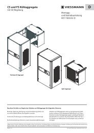
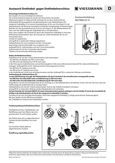
GBExchanging a rotary lever lock for a rotary lever lockDismantling the rotary lever lock (Z):Remove the plug (H) from the inside handle (E).Turn the hexagon socket screw (G) to the left until you notice some slight resistance.The screw (G) is removed from the square pin of the outside handle (B) and at the sametime the spring casing (J), which is integrated inside the handle mount (D), is movedwith the thread insert (K) to the stop point (L) in the handle mount (D), towards theinside handle (E) (starting position for new installation).If the thread insert (K) is not at the stop point (L) in the handle mount (D) then theoutside handle (B) can end up with too much play after installing the handle.Now, if possible, remove the screw (G) with some force through the integrated springcasing (J) or keep turning the screw (G) to the left until it can be removed.Remove the washer (F).Remove the inside handle (E) in a vertical position.Unscrew the handle mount (D) from the inside plate using the 4 screws (the lock catchmust be horizontal).Lift the outside handle (B) by 45° and pull out to the front.Unscrew the outside rosette (A) using the 4 screws.Clean the door panel and the lock's keyway.Assembly information00570063-01 GBZInstalling the rotary lever lock:Screw on the external flange (A) using 4 countersunk screws 5x20- with left-hand DIN the TOP LS mark should be at the top- with right-hand DIN the TOP RS mark should be at the top.Apply some multi-purpose lubricant (for the food industry) into the keyway of the external flange and to moving parts.Insert the outside handle (B) with a 45° incline into the outside flange (A) up to the stop point using the safety lugs on the mandrel- with left-hand DIN a 45° incline to the left- with right-hand DIN a 45° incline to the rightand turn the outside handle (B) backwards to a vertical position.Preparing the handle mount (D):Depending on the DIN direction, the handle mount (D) may have to be pre-adjusted by turning the internal flange.- with left-hand DIN lock catch on right and LS TOP mark up- with right-hand DIN lock catch on left and RS TOP mark upCheck whether the thread insert (K) is at the stop point (L) in the handle mount (D). If this is not the case, the outside handle (B) mayhave too much play after installing the handle.Screw the handle mount (D) to the inside plate of the door panel using 4 countersunk screws 5x20.Push the inside handle (E) in a vertical position onto the handle mount (D).Apply some screw locking compound to the screw thread M8x55 (G) and press forcefully with the washer (F) through the insidehandle (E) into the handle mount (D) through the integrated spring casing (J).Screw the screw (G) down to the stop point. There is automatic distance compensation due to the integrated spring casing (J).Close the opening with the plug (H).The cotter can be retained on the door frame.Functional test of the rotary lever lock:Test the function of the rotary lever lock,lock cylinder and emergency opening firstwith the door open and then with it closed.The wing door can be opened from the insidewhen closed using the emergency opener.The door lock remains closed in thisinstance.DIN linksTOP LSADIN rechtsTOP RSEF GHCheck the emergency opening functionregularly!DABD J K LDIN linksLS TOPDDIN rechtsRS TOPGeneral notice (liability): the details of this technical documents serve for description. Consents regarding the availability of certain features orregarding a certain purpose always require a special written agreement.Page No. 00570063-01 GB Right reserved to make technical changes! 05.09
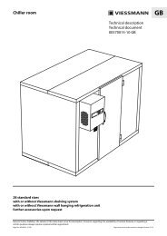
Remplacement d'une serrure à poignée basculanteDémontage de la serrure à poignée basculante (Z) :Retirer le bouchon (H) de la poignée intérieure (E).Tourner la vis à six pans creux (G) vers la gauche jusqu'à ce qu'une légère résistance sefasse sentir. La vis (G) est ainsi dévissée de l'axe carré de la poignée extérieure (B) et lacage à ressort (J) intégrée dans le support du levier (D) est simultanément transportéeavec sa garniture filetée (K) en butée (L) de support du levier (D) dans le sens de lapoignée intérieure (E) (situation initiale pour premier montage).Si la garniture filetée (K) ne se trouve pas en butée (L) dans le support du levier (D), ilse peut que la poignée extérieure (B) ait trop de jeu après son montage.Maintenant, si possible, retirer la vis (G) par la cage à ressort intégrée (J) avec unecertaine force, c'est-à-dire tourner la vis (G) vers la gauche jusqu'à pouvoir la retirer.Enlever la rondelle (F).Ôter la poignée intérieure (E) en position verticale.Dévisser le support du levier (D) de la tôle intérieure par les4 vis (la clenche doit être horizontale).Faire pivoter la poignée extérieure (B) de 45° et la retirer vers l'avant.Dévisser la rosette extérieure (A) par les 4 vis.Nettoyer le vantail de la porte et l'emplacement de la serrure.Notice de montage00570063-01 FZFMontage de la serrure à poignée basculante :Visser la bride extérieure (A) avec 4 vis à tête noyée 5x20- pour une direction d'ouverture à gauche selon la norme DIN, marquage TOP LS en haut- pour une direction d'ouverture à droite selon la norme DIN, marquage TOP RS en hautAppliquer dans le conduit de la bride extérieure et sur les pièces mobiles un peu de lubrifiant universel (pour usage dans l'industrieagroalimentaire). Poignée extérieure (B) en position 45° avec les ergots de positionnement sur la broche- en cas d'ouverture à gauche selon la norme DIN position 45° vers la gauche- en cas d'ouverture à droite selon la norme DIN position 45° vers la droiteEmmancher dans la bride extérieure (A) jusqu'à la butée et refaire pivoter la poignée extérieure (B) en position verticale.Préparation du support du levier (D) :En fonction de la direction d'ouverture selon la norme DIN, il faut prérégler, le cas échéant, le support du levier (D) en tournant labride intérieure.- en cas d'ouverture à gauche selon la norme DIN, clenche à droite et marquage LS TOP en haut- en cas d'ouverture à droite selon la norme DIN, clenche à gauche et marquage RS TOP en haut.Contrôler que la garniture filetée (K) se trouve en butée (L) dans le support du levier (D). Si ce n'est le cas, il se peut que la poignéeextérieure (B) ait trop de jeu après le montage.Visser le support du levier (D) à la tôle intérieure du vantail de porte avec 4 vis à tête noyée 5x20.Relever la poignée intérieure (E) en position verticale sur le support du levier (D).Appliquer un peu de peinture frein sur le filetage de la vis M8x55 (G) et appuyer fortement avec la rondelle (F) par le levier intérieur(E) sur le support du levier (D) grâce à la cage à ressort intégrée (J).Visser la vis (G) jusqu'en butée. Grâce à la cage à ressort intégrée (J), la compensation d'écartement s'effectue automatiquement.Obturer l'ouverture avec le bouchon (H). La gâche du cadre de porte peut être conservée.Vérification du fonctionnement de la serrureà poignée basculante :Contrôler la serrure à poignée basculante, lebarillet et l'ouverture d'urgence d'abordporte ouverte puis porte fermée.On peut ouvrir la porte pivotante del'intérieur lorsqu'elle est fermée grâce audispositif d'ouverture en cas d'urgence.La serrure reste dans ce cas en position fermée.Contrôler régulièrement l'ouvertured'urgence !DIN linksTOP LSBADIN rechtsTOP RSADEF GHD J K LDIN linksLS TOPDDIN rechtsRS TOPIndication générale concernant la garantie : les données indiquées sur cette fiche signalétiques ne sont que descriptives. Tout ce qui peut se rapporterà l'existence de certaines caractéristiques ou pouvant servir dans certains buts sera d'abord préalablement soumis à un accord écrit.Page 00570063-01 F Sous réserve de modifications techniques! Stand 05.09
<strong>Viessmann</strong> Kältetechnik GmbHSchleizer Straße 10095030 Hof/SaaleGermanyPhone +49 (0) 92 81/ 81 4 - 0Fax +49 (0) 92 81/ 81 4 - 2 69info@vkag.dewww.vkag.de