SL-1200MK2 SL-1210MK2 Technics - Audiofanzine
SL-1200MK2 SL-1210MK2 Technics - Audiofanzine
SL-1200MK2 SL-1210MK2 Technics - Audiofanzine

Create successful ePaper yourself
Turn your PDF publications into a flip-book with our unique Google optimized e-Paper software.
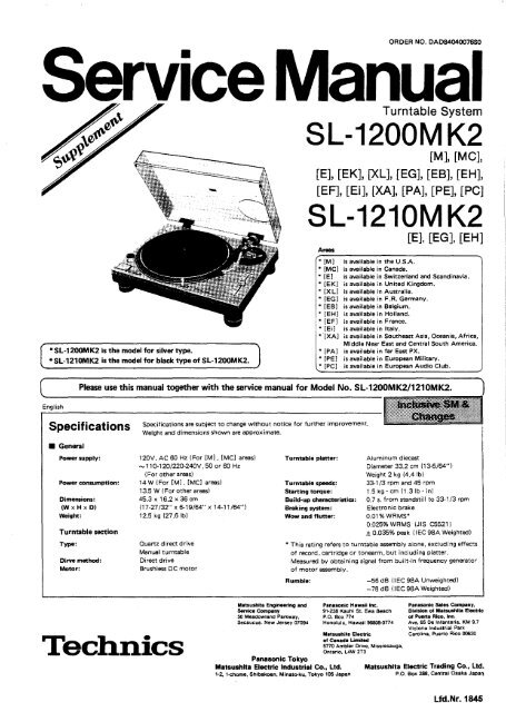
ORDER NO. DAD84040076S0<br />
ervice Manual<br />
Turntable System<br />
<strong>SL</strong>-<strong>1200MK2</strong><br />
[M], [MC],<br />
[E], [EK], [XL], [EG], [EB], [EH],<br />
[EF], [Ei], [XA], [PA], [PE], [PC]<br />
<strong>SL</strong>-<strong>1210MK2</strong><br />
Areas<br />
* [M]<br />
* [MC]<br />
* [E]<br />
* [EK]<br />
* [XL]<br />
* [EG]<br />
* [EB]<br />
• [EH]<br />
* [EF]<br />
• [Eil<br />
* [XA]<br />
*<strong>SL</strong>-<strong>1200MK2</strong> is the model for silver type. * [PA]<br />
*<strong>SL</strong>-<strong>1210MK2</strong> is the modelfor black type of <strong>SL</strong>-<strong>1200MK2</strong>.<br />
* [PEl<br />
* [PC]<br />
English<br />
[E], [EG], [EH]<br />
is available in the U.S.A.<br />
is available in Canada.<br />
is available in Switzerland and Scandinavia.<br />
is available in United Kingdom.<br />
is available in Australia.<br />
is available in F.R. Germany.<br />
is available in Belgium .<br />
is available in Holland.<br />
is available in France .<br />
is available in Italy.<br />
is available in Southeast Asia, Oceania, Africa,<br />
Middle Near East and Centra I South America.<br />
is available in far East PX.<br />
is available in European Military.<br />
is available in European Audio Club.<br />
Please use this manual together with the service manual for Model No. <strong>SL</strong>-<strong>1200MK2</strong>/<strong>1210MK2</strong>.<br />
Specifications<br />
• General<br />
Power supply:<br />
Power consumption:<br />
Dimensions:<br />
(W x H x Dl<br />
Weight:<br />
Turntable section<br />
Type:<br />
Dirve method:<br />
Motor:<br />
Specifications are subject to change without notice tor further improvement.<br />
Weight and dimensions shown are approximate .<br />
120V. AC 60 Hz (For [M]. [MC] areas)<br />
-11 0-120/220-240V. 50 or 60 Hz<br />
(For other areas)<br />
14 W (For [M] • [MC] areas)<br />
13.5 W (For other areas)<br />
45.3 x 16.2 x 36 cm<br />
(17-27/32" x 6-19/64" x 14-11/64")<br />
12.5 kg (27.6Ib)<br />
Quartz d i reet drive<br />
Manual turntable<br />
Direct drive<br />
Brushless DC motor<br />
<strong>Technics</strong><br />
Turntable platter:<br />
Turntable speeds:<br />
Starting torque:<br />
Build-up characteristics:<br />
Braking system:<br />
Wow and flutter:<br />
Aluminum diecast<br />
Diameter 33.2 cm (13-5/64")<br />
Weight 2 kg (4.4 Ib)<br />
33-1/3 rpm and 45 rpm<br />
1.5 kg . cm (1.3 Ib . in)<br />
0.7 s. from standstill to 33-1/3 rpm<br />
Electronic brake<br />
0.01%WRMS*<br />
0.025% WRMS (JIS C5521)<br />
± 0.035% peak (I EC 98A Weighted)<br />
* This rating reters to turntable assembly alone. excluding effects<br />
of record. cartridge or tonearm. but including platter.<br />
Measured by obtaining signal from built-in frequency generator<br />
of motor assembly.<br />
Rumble:<br />
Mabushita Engineering and Panasoftie Hawaii Inc.<br />
Senice Company<br />
91·238 Kauhi St. Ewa Beach<br />
50 Meadowland Parkway, P.O. Box 774<br />
Secaucus. New Jersey 07094 Honolulu. Hawaii 96808-0774<br />
Panasonic Tokyo<br />
Matsushita Electric Industrlal CO., Ltd.<br />
1-2, 1-chome. Shibakoen. Minalo-ku. Tokyo 105 Japan<br />
Uatsushita Electric<br />
ol Canada Umited<br />
5770 Ambler Drive, Mississauga.<br />
Onlario. L4W 2T3<br />
-56 dB (IEC 98A Unweighted)<br />
-78 dB (lEC 98A Weighted)<br />
Panasonic Sales Company.<br />
Division ol Matsushita Electric<br />
ol Puerto Rico. Inc.<br />
Ave. 65 De Infanteria. KM 9.7<br />
Victoria Induslrial Park<br />
Carolina. Puerto Rico 00630<br />
Matsushita Electric Trading Co_, Ltd.<br />
P.O. Box 288. Central Osaka Japan<br />
Lfd.Nr. 1845
• Tonarm<br />
Franc;:ais<br />
Typ:<br />
Effektive Länge:<br />
Tonarmhöhe-<br />
Einstellbereich :<br />
Oberhang:<br />
Effektive Masse:<br />
Spurfehlwinkel:<br />
Kröpfungswinkel:<br />
Lagerreibung :<br />
Universal-Tonarm<br />
230mm<br />
CARACTERISTIQUES<br />
• Généralités<br />
Alimentation:<br />
Consomrnation:<br />
Dimensions:<br />
(L x H xP)<br />
Poids:<br />
• Platine de lecture<br />
Type:<br />
Système d'entrainement:<br />
Moteur:<br />
Plateau de lecture:<br />
Vitesses de rotation:<br />
Couple de dérnarrage:<br />
Caractéristiques<br />
d'augmentation:<br />
Système de freinage:<br />
Pleurage et scintillement:<br />
0-6mm<br />
15 mm<br />
12 9 (ohne Tonabnehmer)<br />
2°32' bei der Einlaufrille einer<br />
30 cm-Platte<br />
0°32' bei der Auslaufrille einer<br />
30 cm-Platter<br />
22°<br />
Weniger als 7 mg (horizontal, vertikal)<br />
<strong>SL</strong>-<strong>1200MK2</strong>/<strong>1210MK2</strong><br />
Auflagekraft<br />
Einstellbereich :<br />
Zulässiger Tonabnehmer<br />
Gewichtbereich:<br />
(mit Zusau<br />
Gegengewichtl :<br />
Gewichtbereich :<br />
(mit ZusaUgewicht)<br />
Tonarmkopf-Gewicht:<br />
0- 2,5 9<br />
Les spécifications sont susceptibles d'être modifiées sans préavis.<br />
Le poids et les dimensions donnés sont approximatifs .<br />
Alternatif 11 0-120/220-240 V,<br />
50 ou 60 Hz<br />
13,5W<br />
45,3 x 16.2 x 36 cm<br />
12,5 kg<br />
Entainement direct à quartz<br />
Platine manuelle<br />
Entrainement 9irect<br />
Moteur C.C. sans balai<br />
Aluminium moulé sous pression<br />
Diamètre 33.2 cm<br />
Poids 2 kg<br />
33-1/3 et 45t/p.m.<br />
1,5 kg· cm<br />
0,7 s. (rotation de 90°) à 33-1/3 t/p.m.<br />
Frein électronique<br />
0,01% de valeur efficace*<br />
0,025% de valeur efficace (J IS C5521 )<br />
± 0,35% de crête (I EC 98A Pondéré)<br />
"Ce régime nominal se rapporte à I'ensemble du tournediSQue<br />
seul, excluant les eftets du diSQue, de la cellule piek-up ou de<br />
bras de lecture, mais comprenant Ie plateau.<br />
Mesuré par I'obtention d'un signal provenant du générateur<br />
de fréquences incorporé de-l'ensemble du moteur.<br />
Ronflement: -56 dB (I EC 98A Non pondéré)<br />
-78 dB (lEC 98A Pondéré)<br />
3<br />
• . Bras de lecture<br />
Type:<br />
Longueur effec:tive:<br />
Portée du riglage de la<br />
hauteur de bras:<br />
Porte-è-faux:<br />
Massa ráelle:<br />
Angle d'erreur de piste:<br />
Angle de décalage:<br />
Frottement:<br />
Plage de riglage de la<br />
pr_ion d'appui:<br />
Gamme du poids de la<br />
caIluie piek-up<br />
utilisabie:<br />
(avee contrepoids<br />
auxiliaire):<br />
(.vee contrepoids de<br />
la caIluie):<br />
Poids de la ceIluie:<br />
6- 10g<br />
13,5 - 17 9 (einschlieBlich Tonarmkopf)<br />
9,5 -13g<br />
17 - 20.5 9 (einschlieBlich Tonarmkopf)<br />
3,5 - 6.5 9<br />
11 - 14 9 (einschlieBlich Tonarmkopf)<br />
7,5 9<br />
Bras de lecture universel<br />
230mm<br />
0-6mm<br />
15mm<br />
12 9 (sans la cellule piek-up)<br />
En deçà de 2°32' au sillon extérieur<br />
d'un diSQue de 30 cm<br />
En deçà de 0°32' au sillon intérirue<br />
d'un diSQue de 30 cm<br />
22°<br />
Moins de 7 mg liatéral et vertical)<br />
o -2.5g<br />
6-10g<br />
13,5 - 17,5 9<br />
(V compris la coque porte-ceIluie)<br />
9,5 - 13 9<br />
17 - 20,59<br />
(V compris la ccique porte-ceIluie)<br />
3,5 - 6,5 9<br />
11 - 14 9<br />
(V compris la coque porte-ceIluie)<br />
7,59
L-<strong>1200MK2</strong>/<strong>1210MK2</strong><br />
• MEASUREMENTS AND ADJUSTMENTS----English-----<br />
• Conditions of set, and instruments used<br />
1. Remove the panel cover.<br />
2. Remove thibottom cover (when adjusting the pitch<br />
control gain).<br />
1<br />
Adjustment Connection<br />
.- . -<br />
Pitch control ± 0%<br />
adjustment<br />
Frequency counter<br />
(+) - TP27<br />
(-) ..,.. Earth point<br />
Tester<br />
Pitch control gain<br />
2 (+) - CN102 terminal @<br />
adjustment<br />
(-) - CN102 terminal @<br />
3 Brake adjustment<br />
Parts<br />
adjusted<br />
3. Frequency counter<br />
4. Tester<br />
Procedure<br />
1. Connect the frequency counter and turn the<br />
power supply ON .<br />
VR301 2. Set the pitch control knob to "0".<br />
(Fig. 3) (Indicator lights up.)<br />
3. Adjust VR301 so that the frequency is<br />
262.08 kHz ± 0.05 kHz.<br />
VR302<br />
(Fig. 4)<br />
VR201<br />
(Fig. 3)<br />
1. Set the pitch control knob to "0".<br />
2. Pull out the connector CN102 of drive P.C.B.<br />
3. Connect the tester to terminals,@and@of<br />
connector CN102 on the pitch control P.C.B.<br />
side.<br />
4. Adjust VR302 so that the resistance value of<br />
the tester is 2.7 kn ± 0.1 kno<br />
1. Adjust VR201 so that the rotation at<br />
33 r.p.m. stops within the angle of 90° _120°<br />
after depressing the stop bLitton .<br />
• MESSUNGEN UND JUSTIERUNGEN,-----Deulsch-----<br />
• Zustand des Gerätes und zu verwendende Instrumente<br />
1. Die Abdeckplatte entfernen.<br />
2. Die Bodenadbeckung entfernen (wenn die Drehzahlregelungs<br />
Verstärkung justiert werden soli).<br />
1<br />
Justierung Anschlüsse<br />
± O%-Justierung des<br />
Drehzahlreglers<br />
Frequenzzähler<br />
(+) - TP27<br />
(-) - Massepunkt<br />
Justierung der Prüfgerät<br />
2 Drehzahlregelungs- _ 1-(+) -CN102 AnschluB@<br />
Verstärkung (-) - CN102 AnschluB@<br />
Zu justierender<br />
Teile<br />
3. Frequenzzähler<br />
4. Prüfgerät<br />
Vorgehen<br />
1. Frequenzzähler anschlieBen und Netzschalter<br />
einschalten.<br />
VR301 2. Drehzahlreglerknopf aut "0" stellen.<br />
(Abb.3) (Anzeige leuchtet auf.)<br />
3. VR301 sa justièren, daB die Frequenz<br />
262,08 kHz ± 0,05 kHz beträgt.<br />
1. Den Drehiahlreglerknopf auf "0" einstellen.<br />
2. Steckverbindung CN102 von der<br />
Antriebsplatine hrausziehen.<br />
VR302 3. Prüfgerät an Anschlüsse@und@der<br />
(Abb.4) Steckverbindung CN1 02 auf der<br />
Drehzahlreglerseite der Platine anschlieBen.<br />
4. VR302 sa justieren, daB der Widerstandswert<br />
des Prüfgerätes 2,7 kn ± 0,1 kn beträgt.<br />
1. VR201 sa justieren, daB die Rotation bei<br />
VR201<br />
3 Brernsjustierung 33 UPM innerhalb 90° -- 120 0<br />
nach Drücken<br />
(Abb.3)<br />
der Stop-Taste stoppt.<br />
-8-
.- MESURAGES ET RÉGLAGES-----iIIIiIII--Français----<br />
• Conditions de I'appareil et appareils utilisés.<br />
1. Retirer Ie panneau de protection.<br />
2. Retirer Ie panneau de protection inférieur (lors de I'ajusternent<br />
de I'amplification du réglage d'écart).<br />
1<br />
Mise au point Rflccordement'<br />
--<br />
Elements à<br />
regier<br />
3. Compteur de fréquence<br />
4. Appareil controleur<br />
Marche à suivre<br />
Compteur de fréquence<br />
1. Raccorder Ie compteur de fréquence et mettre<br />
en marche I'alimlmtaiton.<br />
Ajustement de ±. 0% (+) - TP27 VR301 2. Régler Ie bouton du réglage d'écart sur "0".<br />
du réglage d' écart (-) - Point de contact à (Fig. 3) (L'indicateur s'éclairera.)<br />
la terre 3. Ajuster VR301 de telle sorte que la fréquence<br />
soit de 262,08 kHz ±. 0,05 kHz.<br />
Ajustement de Appareil controleur<br />
2 I'amplification du (+) - Borne CN102 @<br />
réglage d'écart -(-) - Borne CN102 @<br />
3 Ajustement du frein<br />
1. Régler Ie bouton de réglage d'écart sur "0".<br />
2. Retirer Ie connecteur CN102 de la plaquette<br />
à circuits imprimés de commande.<br />
3. Raccorder I'appareil controleur aux bornes<br />
VR302 @ et @du connecteur CN102 sur Ie cäté de<br />
(Fig. 4) la plaquette à circuits imprimés du réglage<br />
d'écart.<br />
4. Ajuster VR302 de telle sorte que la valeur de<br />
résistance de I'appareilcontroleur soit de<br />
2,7 kn ±. 0,1 kno<br />
1. Régler VR201 de telle sorte que la rotation<br />
.. _----- --- - -- VR201 à 33 t/p;m. s'arrêteen deçà d'un-angle de<br />
(Fig. 3) 90° - 120° après avoir appuyé sur la touche<br />
d'arrêt.<br />
• MEDICIONES Y AJUSTE ---------Espano.----<br />
• Condiciones de aparato e instrumentos usados<br />
1. Remover la cubierta del panel.<br />
2. Remover la cubierta interior (al ajustar la ganancia de<br />
control de altura de los sonidos).<br />
--<br />
1<br />
2<br />
Ajuste Conexión<br />
Ajuste ±. 0% de<br />
control de altura<br />
Ajuste de ganancia<br />
de contral de altura<br />
3 Ajuste de freno<br />
Contador de frecuencia<br />
(+) - TP27<br />
(-) - Punto de tierra<br />
Probador<br />
(+) - Terminal de CNl 02 @<br />
(-) -Terminal de CN102@<br />
-9-<br />
Piezas<br />
ajustadas<br />
3. Contador de frecuencia<br />
4. Probador<br />
Procedimiento<br />
1. Conectar el contador de frecuencia y prender<br />
la fuente de alimentación.<br />
VR301 2. Ajustar la perilla de control de altura de<br />
(Fig. 3) sonidos a "0". (EI indicador se ilumina.)<br />
3. Ajustar VR301 de manera que la frecuencia<br />
sea 262,08 kHz ±. 0,05 kHz.<br />
1. Poner el control de altura de sonidos en "0".<br />
2. Sacar el conector CN102 de T.C.I. de<br />
accionamiento.<br />
VR302 3. Conectar el probador a terminales,@y@de<br />
(Fig. 4) conector CN102 dellado de T.C.I. de control<br />
de altura.<br />
4. Ajustar VR302 de manera que el valor de<br />
resistencia del probador sea 2,7 kn ±. 0,1 kno<br />
VR201<br />
(Fig. 3)<br />
1. Ajustar VR201 de manera que la rotación a<br />
33 r.p.m. se pare dentro del ángulo de<br />
90° _ 120 0 después oprimir el botón de parada
<strong>SL</strong>-t200MK2<br />
• PARTS IDENTIFICATION<br />
H<br />
45-rpm adal:)'tOr<br />
TumtabJe base<br />
Turntabie<br />
Arm::lamp<br />
CenWr spindie<br />
Turntabie<br />
Strobe-illuminatori<br />
pilot lamp<br />
Stan stop button<br />
Speed select buttons<br />
Fig_ 41<br />
Fig.5 i<br />
Fig_6<br />
.. L<br />
Arm-height adjustment ring<br />
Baiance weight<br />
Stylus pressure<br />
Arm<br />
Anti-skating control knob<br />
Styius illuminator<br />
Cueing lever<br />
Arm<br />
Tonearm<br />
?i,ch indicator<br />
Pitch control knob<br />
Locking nt.a<br />
Headshei!<br />
illuminator switch<br />
Fig. 10<br />
Fig. 7<br />
Fig. 8<br />
Fig. 9
Panasonic<br />
<strong>Technics</strong><br />
Panasonic Service Dokumentations-Center<br />
Postfoch4706 53<br />
0-12315 Berin<br />
Telefon 0 30/723 a 1-3<br />
Telefax 0 30/723 81 SOO