
You also want an ePaper? Increase the reach of your titles
YUMPU automatically turns print PDFs into web optimized ePapers that Google loves.
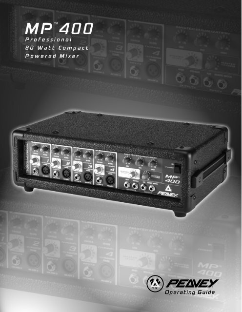
<strong>MP</strong><br />
<br />
<strong>400</strong><br />
Professional<br />
80 Watt Compact<br />
Powered Mixer<br />
Operating Guide
Intended to alert the user to the presence of uninsulated “dangerous voltage” within the product’s<br />
enclosure that may be of sufficient magnitude to constitute a risk of electric shock to persons.<br />
Intended to alert the user of the presence of important operating and maintenance (servicing)<br />
instructions in the literature accompanying the product.<br />
CAUTION: Risk of electrical shock — DO NOT OPEN!<br />
CAUTION: To reduce the risk of electric shock, do not remove cover. No user serviceable parts inside. Refer<br />
servicing to qualified service personnel.<br />
WARNING: To prevent electrical shock or fire hazard, do not expose this appliance to rain or moisture. Before<br />
using this appliance, read the operating guide for further warnings.<br />
Este símbolo tiene el propósito, de alertar al usuario de la presencia de “(voltaje) peligroso” sin aislamiento<br />
dentro de la caja del producto y que puede tener una magnitud suficiente como para constituir<br />
riesgo de descarga eléctrica.<br />
Este símbolo tiene el propósito de alertar al usario de la presencia de instruccones importantes sobre la<br />
operación y mantenimiento en la información que viene con el producto.<br />
PRECAUCION: Riesgo de descarga eléctrica ¡NO ABRIR!<br />
PRECAUCION: Para disminuír el riesgo de descarga eléctrica, no abra la cubierta. No hay piezas útiles dentro.<br />
Deje todo mantenimiento en manos del personal técnico cualificado.<br />
ADVERTENCIA: Para evitar descargas eléctricas o peligro de incendio, no deje expuesto a la lluvia o humedad<br />
este aparato Antes de usar este aparato, Iea más advertencias en la guía de operación.<br />
Ce symbole est utilisé dans ce manuel pour indiquer à l’utilisateur la présence d’une tension dangereuse<br />
pouvant être d’amplitude suffisante pour constituer un risque de choc électrique.<br />
Ce symbole est utilisé dans ce manuel pour indiquer à l’utilisateur qu’il ou qu’elle trouvera d’importantes<br />
instructions concernant l’utilisation et l’entretien de l’appareil dans le paragraphe signalé.<br />
ATTENTION: Risques de choc électrique — NE PAS OUVRIR!<br />
ATTENTION: Afin de réduire le risque de choc électrique, ne pas enlever le couvercle. Il ne se trouve à l’intérieur<br />
aucune pièce pouvant être reparée par l’utilisateur. Confiez I’entretien et la réparation de l’appareil à un réparateur<br />
<strong>Peavey</strong> agréé.<br />
AVERTISSEMENT: Afin de prévenir les risques de décharge électrique ou de feu, n’exposez pas cet appareil à la<br />
pluie ou à l’humidité. Avant d’utiliser cet appareil, lisez attentivement les avertissements supplémentaires de ce<br />
manuel.<br />
Dieses Symbol soll den Anwender vor unisolierten gefährlichen Spannungen innerhalb des Gehäuses<br />
warnen, die von Ausreichender Stärke sind, um einen elektrischen Schlag verursachen zu können.<br />
Dieses Symbol soll den Benutzer auf wichtige Instruktionen in der Bedienungsanleitung aufmerksam<br />
machen, die Handhabung und Wartung des Produkts betreffen.<br />
VORSICHT: Risiko — Elektrischer Schlag! Nicht öffnen!<br />
VORSICHT: Um das Risiko eines elektrischen Schlages zu vermeiden, nicht die Abdeckung enfernen. Es befinden<br />
sich keine Teile darin, die vom Anwender repariert werden könnten. Reparaturen nur von qualifiziertem<br />
Fachpersonal durchführen lassen.<br />
ACHTUNG: Um einen elektrischen Schlag oder Feuergefahr zu vermeiden, sollte dieses Gerät nicht dem Regen<br />
oder Feuchtigkeit ausgesetzt werden. Vor Inbetriebnahme unbedingt die Bedienungsanleitung lesen.<br />
2
ENGLISH<br />
<strong>MP</strong> <strong>400</strong><br />
Powered Mixer<br />
Thank you for purchasing the <strong>Peavey</strong> <strong>MP</strong> <strong>400</strong>! The <strong>MP</strong> <strong>400</strong> is a four-channel, powered mixer<br />
packed into an amazing compact package. Featuring only the essential requirements for a sound<br />
reinforcement mixer, the <strong>MP</strong> <strong>400</strong> is a breeze to operate and a joy to own. Quality semiconductor<br />
components lend a hand to achieve the excellent audio characteristics and reliable service<br />
that has made the <strong>MP</strong> Series Mixer so well known.<br />
The <strong>MP</strong> <strong>400</strong> boasts four discrete channels, each with high and low impedance inputs, a Contour<br />
high frequency EQ control, and Reverb and Level controls. The master section offers a three-band<br />
equalizer, Master Level and Reverb controls, 1/4" Main and Reverb/Aux Outputs, Aux Input, and<br />
Remote Switch Input.<br />
The following guide explains the <strong>MP</strong> <strong>400</strong> features and the proper operation of each. Refer to the<br />
diagrams in each section to locate each feature by its designated number. Throughout this guide,<br />
related features will sometimes refer you to another feature using this number system. Let’s begin<br />
by listing the main features of the <strong>MP</strong> <strong>400</strong>.<br />
FEATURES:<br />
• Four total input channels<br />
• Reverb control on each channel<br />
• Contour high frequency equalizer on each channel<br />
• 1/4" and XLR inputs on each input channel<br />
• 1/4" Main Output<br />
• 1/4" Aux/Reverb Output<br />
• 1/4" Aux Input<br />
• 1/4" Remote Switch for reverb defeat<br />
• Master Three-band Equalizer<br />
• Master Level and Reverb controls<br />
• 80 W power amp<br />
3
POWER<br />
This section describes the proper application of AC power to your <strong>MP</strong> <strong>400</strong>. To insure the safety<br />
of you and your <strong>MP</strong> <strong>400</strong>, please pay close attention to any designated cautions.<br />
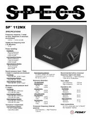
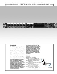
REAR PANEL<br />
1 4<br />
1. IEC POWER SOCKET:<br />
With the Power Switch (#2) in the off (O) position, plug the power cord into this connector<br />
prior to plugging it into your AC power source. Always insure that proper grounding practices<br />
are utilized. Damage to the equipment may occur if improper line voltage is used (see voltage<br />
marking on unit). Never remove or cut the ground pin of the line cord plug.<br />
NOTE: FOR UK ONLY<br />
As the colors of the wires in the mains lead of this apparatus may not correspond with the<br />
colored markings identifying the terminals in your plug, proceed as follows: (1) The wire which<br />
is colored green and yellow must be connected to the terminal which is marked by the letter<br />
E, or by the earth symbol, or colored green or green and yellow. (2) The wire which is colored<br />
blue must be connected to the terminal which is marked with the letter N, or the color black.<br />
(3) The wire which is colored brown must be connected to the terminal which is marked with<br />
the letter L or color red.<br />
2. POWER SWITCH (See front panel diagram next page)<br />
Place this switch in the “ON” position to turn the unit on.<br />
3. POWER LED (See front panel diagram next page)<br />
Illuminates when AC power is being supplied to the mixer.<br />
SPEAKER CONNECTIONS<br />
This section will help you locate the two speaker output jacks on the rear of your <strong>MP</strong> <strong>400</strong>.<br />
WARNING: NEVER ALLOW YOUR TOTAL SPEAKER I<strong>MP</strong>EDANCE TO DROP BELOW<br />
THE MINIMUM I<strong>MP</strong>EDANCE OF 4 OHMS.<br />
4. SPEAKER OUTPUTS<br />
Two parallel 1/4" jacks are provided at the output of the power amplifier for ease of speaker<br />
connection. Minimum speaker impedance (min. load) is 4 ohms.<br />
4
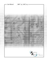
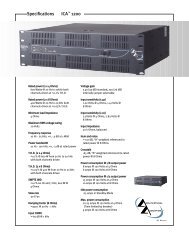
CHANNEL FEATURES (CHANNELS 1-4)<br />
The following section describes channels 1-4. Each of these input channels is identical.<br />
9 8 12<br />
3 2<br />
6 7 5 10 13 14 15 11 16<br />
5. MIC (LOW Z) INPUT<br />
XLR balanced low impedance channel input optimized for a microphone or other low<br />
impedance source. Pin 2 is the positive input. This connector has +15V phantom power<br />
supply on Pins 2 and 3 at all times (Pin 1 is the ground reference).<br />
WARNING: BECAUSE THE LOW-Z INPUTS HAVE PHANTOM POWER, ONLY CONNECT<br />
MICROPHONES OR PRODUCTS WITH A BALANCED OUTPUT TO PREVENT DAMAGE.<br />
IF YOU ARE UNSURE, PLEASE CHECK THE PRODUCT’S OPERATING INSTRUCTIONS.<br />
6. LINE (HIGH Z) INPUT<br />
1/4" unbalanced input that accepts line level sources equipped with a 1/4" plug (TS). The two<br />
inputs (XLR and 1/4") cannot be used simultaneously.<br />
7. LEVEL<br />
Sets the level of the individual channel in the mix.<br />
8. REVERB<br />
Sets the level of the internal reverb for the channel and must be used in conjunction with the<br />
master reverb level. It is post gain and will be affected by the LEVEL (7) adjustment. The<br />
Reverb/Aux control also determines the level of signal sent to the Effects Output (14).<br />
9. CONTOUR<br />
A shelving type of active tone control that varies the treble frequency level ±15 dB at 10 kHz.<br />
It is designed to remove noise or to add brilliance to the signal, depending on the quality of<br />
the source.<br />
5
MASTER FEATURES<br />
10. MASTER LEVEL CONTROL<br />
Controls the overall volume level of the system.<br />
11. MASTER REVERB CONTROL<br />
Controls the amount of reverb that will be heard in the main mix.<br />
12. MASTER EQUALIZATION<br />
Provides ±15 dB equalization at each center frequency. EQ boost is obtained by moving a<br />
particular EQ band’s control above the “0” position. EQ cut is obtained by moving a particular<br />
EQ band’s control below the “0” position. The following list describes each EQ control and its<br />
center frequency.<br />
Low - shelving type - 80 Hz<br />
Mid - peak type - 1 kHz<br />
High - shelving type - 10 kHz<br />
OPERATION NOTE: This equalizer is designed to provide room equalization, feedback<br />
control and system tone control. No amount of equalization will correct the response curve<br />
of a poor loudspeaker. Always begin with all controls in the “0” position and avoid excessively<br />
cutting large segments of the audio passband, which would limit the system’s dynamic range.<br />
13. MAIN OUTPUT<br />
1/4" unbalanced output that can be used as a source for an external amplifier/speaker<br />
system feed to other mixers or a tape deck.<br />
14. REVERB/AUX OUTPUT<br />
Plugging into this mono (TS) 1/4" output allows you to utilize external effects devices. In order<br />
to return the signal from the external effects unit, use the Aux Input (15). Simply turn the<br />
Reverb Master down to defeat the Internal Reverb if desired.<br />
15. AUX INPUT<br />
Use this mono 1/4"(TS) input to insert a line-level signal into the main mix. This signal can<br />
originate from a variety of sources including instrument/mic preamps, external effects<br />
(see #14), and even an additional sub mixer. This input bypasses the reverb and can be<br />
controlled by the Master EQ and Level.<br />
16. REVERB FOOTSWITCH<br />
Provided for connection of the optional remote footswitch (5100). The footswitch is used to<br />
activate/defeat the reverb.<br />
6
Note: All specifications are typical unless otherwise noted.<br />
0 dBV = 1 Volt RMS<br />
0 dBu = .778 Volts RMS<br />
All specs are referenced to nominal output level (0 dBV)<br />
unless otherwise noted.<br />
All measurements are wideband 20 Hz to 20 kHz unless<br />
otherwise noted.<br />
All control settings are nominal (50% rotation) unless<br />
otherwise noted.<br />
CHANNEL:<br />
Equivalent Input Noise<br />
-116 dBV @ 40 dB Max Gain<br />
Frequency Response:<br />
(To Speaker Outputs)<br />
±3 dB 20 Hz to 20 kHz<br />
Distortion: @ (1 kHz):<br />
Less than .009%<br />
Input Impedance:<br />
Low Z Bal. 2K ohms<br />
1/4" Mic Input 22K ohms<br />
CHANNEL EQ:<br />
Contour EQ:<br />
±15 dB @ 10 kHz Minimum<br />
Center Detent flat ±2 dB<br />
Nominal Channel Gain:<br />
Line = 0 dB<br />
Low Z = 30 dB<br />
Maximum Channel Gain:<br />
Low Z = 50 dB<br />
Line = 19 dB<br />
Nominal Input Level:<br />
Low Z = -30 dB<br />
Line = 0 dB<br />
Minimum Input Level:<br />
Low Z = -50 dB<br />
Line = -19 dB<br />
Maximum Input Level:<br />
Low Z =-11 dB<br />
Line = +28 dB<br />
Phantom Power:<br />
+15 VDC<br />
MASTER:<br />
Gain<br />
Main: = 10 dB (variable)<br />
<strong>MP</strong> <strong>400</strong> SPECIFICATIONS<br />
7<br />
High EQ:<br />
± 15 dB @ 12 kHz Minimum<br />
Center Detent flat ±2 dB<br />
Mid EQ:<br />
± 15 dB @ 1 kHz Minimum<br />
Center Detent flat ±2 dB<br />
Low EQ:<br />
± 15 dB @ 60 HZ Minimum<br />
Center Detent flat ±2 dB<br />
Maximum Output Level:<br />
Main: = + 18 dBV (8.0 V RMS)<br />
Effects: = + 18 dBV (8.0 V RMS)<br />
Nominal Headroom:<br />
Main: = 18 dB<br />
Effects: = 18 dB<br />
Output Impedance:<br />
Main: = 100 ohms<br />
Effects: = 100 ohms<br />
Output Noise:<br />
Residual: -95<br />
(Master Level Down)<br />
Bus: -93<br />
(Master Nominal, All Channel Level Full CCW, Reverb Level Down)<br />
Nominal: -78<br />
(All Controls Nominal, Low Z Input Terminated 150 Ohms)<br />
Signal to noise ratio:<br />
Microphone input to speaker output (>80 dB)<br />
Frequency Response: 20 Hz to 20 kHz<br />
SYSTEM DYNAMIC RANGE:<br />
95 dB<br />
POWER A<strong>MP</strong> SECTION:<br />
Frequency Response:<br />
+0, -3 dB, 30 Hz to 28 kHz @ Rated Power<br />
RATED POWER AND LOAD:<br />
80 W RMS into 4 ohms<br />
55 W RMS into 8 ohms<br />
THD less than .5% Mic input to speaker output 1 kHz at rated<br />
power. Speaker system Impedance: 4 ohms minimum.<br />
Power Requirements:<br />
150W @ 100V, 120V, 230 VAC 50/60 Hz.<br />
Specifications are subject to change without notice.
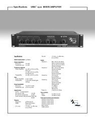
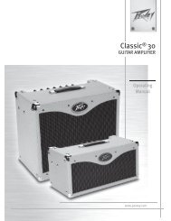
<strong>MP</strong> <strong>400</strong> BLOCK DIAGRAM<br />
8
<strong>MP</strong> <strong>400</strong> RECOMMENDED HOOKUP<br />
9
DEUTSCH<br />
<strong>MP</strong> <strong>400</strong><br />
Power-Mixer<br />
Danke, daß Sie sich für den <strong>Peavey</strong> <strong>MP</strong> <strong>400</strong> entschieden haben! Der <strong>MP</strong> <strong>400</strong> ist ein 4-Kanal<br />
Power-Mixer, der in einem erstaunlich kleinen Gehäuse untergebracht ist. Ausgestattet nur mit den<br />
nötigsten Anforderungen an einen Power-Mixer, ist der <strong>MP</strong> <strong>400</strong> kinderleicht in der Bedienung und<br />
bereitet seinem Besitzer die reinste Freude. Hochwertige Halbleiterkomponenten verhelfen dem<br />
<strong>MP</strong> <strong>400</strong> zu seinen exzellenten Klangwerten und seiner Zuverlässigkeit, die die <strong>MP</strong> Serie Mischpulte<br />
so bekannt gemacht haben.<br />
Der <strong>MP</strong> <strong>400</strong> wartet mit 4 diskret-aufgebauten Kanälen auf; jeder mit 2 Eingängen (high- / low-<br />
Impedanz), einem Contour Equalizer für die Höhen, Reverb und Lautsärke-Regler. Die Master-<br />
Sektion ist mit einem 3-Band Equalizer, Master Level und Reverb Reglern, 1/4" Reverb- und Aux -<br />
Ausgängen, Aux-Eingang und einem Fußschalter-Eingang ausgestattet.<br />
Die folgende Bedienungsanleitung erklärt die Austattungsmerkmale des <strong>MP</strong> <strong>400</strong> und deren<br />
Bedienung. In den Zeichnungen finden Sie die einzelnen Sektionen und deren Bedienelemnte<br />
anhand der Nummern. Im Laufe der Bedienungsanleitung verweisen wir Sie auf weitere<br />
Bedienhinweise, die im Zusammenhang stehen. Sie finden diese auch anhand des<br />
Numerierungssystems. Fangen wir mit der Aufzählung der wichtigsten Austattungsmerkmale des<br />
<strong>MP</strong> <strong>400</strong> an.<br />
ÜBERSICHT:<br />
• 4 volle Eingangskanäle<br />
• Reverb-Regler in jedem Kanalzug<br />
• Contour Equalizer für die Höhen in jedem Kanalzug<br />
• 1/4" Klinke und XLR Eingänge in jedem Kanalzug<br />
• 1/4" Klinke Main Ausgang<br />
• 1/4" Klinke Aux/Reverb Ausgang<br />
• 1/4" Klinke Aux Eingang<br />
• 1/4" Klinke Fußschalter-Eingang zum Ein- /Ausschalten des Reverbs<br />
• 3-Band Equalizer in der Mastersektion<br />
• Master Level- und Reverb Regler<br />
• 80W Endstufe<br />
10
POWER<br />
Dieser Abschnitt beschreibt den richtigen Anschluß Ihres <strong>MP</strong> <strong>400</strong> an eine Wechselstrom-<br />
Spannungsquelle. Um Ihre und die Sicherheit Ihres <strong>MP</strong> <strong>400</strong> zu gewährleisten, achten Sie bitte auf<br />
die Warnhinweise.<br />
GERÄTERÜCKSEITE<br />
1 4<br />
1. EURO-NETZBUCHSE<br />
Stecken Sie das Netzkabel bei ausgeschaltetem Gerät (Netzschalter(#2) in der Aus (0)<br />
Position) in das Gerät, bevor Sie es mit einer Steckdose verbinden. Stellen Sie sicher, daß<br />
die richtige Erdung gewährleistet ist. Legen Sie eine falsche Netzspannung an, besteht die<br />
Gefahr, dass das Gerät beschädigt wird (beachten Sie die Spannungsangabe an dem Gerät).<br />
Entfernen Sie keinesfalls den Erdungspol des Netzsteckers.<br />
2. N ETZSCHALTER (Siehe Frontskizze auf der nächsten Seite)<br />
Bringen Sie den Schalter in die „EIN" Stellung, um das Gerät einzuschalten.<br />
3. POWER LED (Siehe Frontskizze auf der nächsten Seite)<br />
Leuchtet, wenn das Gerät mit Strom versorgt wird<br />
LAUTSPRECHERANSCHLÜSSE<br />
Dieser Abschnitt wird Ihnen dabei helfen die Klinkenbuchsen für den Anschluß der Lautsprecher an<br />
der Rückseite Ihres <strong>MP</strong> <strong>400</strong> zu finden.<br />
Warnung: Achten Sie darauf, daß die Gesamtimpedanz der angeschlossenen<br />
Lautsprecher niemals unter 4 Ohm fällt.<br />
4. LAUTSPRECHERAUSGÄNGE<br />
Zwei parallel-geschaltete 1/4" Klinken sind zum einfacheren Anschluß, am Ausgang der<br />
Endstufe angebracht. Die minimale Impedanz (Mindestlast) beträgt 4 Ohm.<br />
11
KANALAUSTATTUNG (KANÄLE 1-4)<br />
Der folgende Abschnitt beschreibt die Kanäle 1-4. Diese Eingangskanäle sind identisch.<br />
9 8 12<br />
3 2<br />
6 7 5 10 13 14 15 11 16<br />
5. MIC (LOW Z) INPUT<br />
Symmetrische XLR-Eingang zum Anschluß niederohmiger Mikrofone oder anderer<br />
niederohmiger Signalquellen. Pin 2 ist der Pluspol. Dieser Eingang wird immer mit +15V<br />
Phantomspeisung zwischen Pin 2 und 3 versorgt (Pin 1 ist Masse).<br />
WARNUNG: DA DIESE NIEDEROHMIGEN EINGÄNGE IMMER MIT PHANTONSPANNUNG<br />
VERSORGT WERDEN, SCHLIESSEB SIE BITTE NUR MIKROPHONE ODER GERÄTE MIT<br />
SYMMETRISCHEN AUSGÄNGEN AN, UM SCHÄDEN ZU VERMEIDEN. FALLS SIE SICH<br />
NICHT SICHER SIND, LESEN SIE BITTE DIE GEBRAUCHSANWEISUNG DES<br />
JEWEILIGEN GERÄTS.<br />
6. Line (HIGH Z) Input<br />
Unsymmetrische 1/4" Klinkeneingang für hochpegelige Signalquellen mit 1/4"<br />
Klinkenausgängen. Die beiden Eingänge (XLR und Klinke) können nicht gleichzeitig benutzt<br />
werden.<br />
7. LEVEL<br />
Regelt die individuelle Lautstärke des Kanals in der Mischung.<br />
8. REVERB<br />
Regelt den Hallanteil des eingebauten Hallgeräts für den Kanal und muss mit dem<br />
Master-Reverb-Regler benutzt werden. Das Originalsignal wird nach dem Levelregler (7)<br />
abgegriffen und wird daher von diesem beeinflußt. Der Reverb/Aux Regler bestimmt<br />
außerdem den Pegel, der zum Effekt-Ausgang geschickt wird (14).<br />
9. CONTOUR<br />
Ein Shelving-EQ regelt die Höhen bei 10 kHz um ±15 dB. Er ist so ausgelegt, daß er<br />
Störgeräusche absenkt, oder das Signal „brillanter" macht, je nach Qualität der Quelle.<br />
12
MASTER BEREICH<br />
10. MASTER LEVEL CONTROL<br />
Regelt die Gesamtlautstärke des Systems<br />
11. MASTER REVERB CONTROL<br />
Regelt den Hallanteil der Gesamtmischung<br />
12. MASTER EQ<br />
Regelt um ±15 dB im Bereich der Center-Frequenz. Eine Anhebung des entsprechenden<br />
Frequenzbereichs wird durch Drehung des entsprechenden Reglers über die „0"-Position<br />
bewirkt. Eine Absenkung des entsprechenden Frequenzbereichs wird durch Drehung des<br />
entsprechenden Reglers unter die „0"-Position bewirkt. Die folgende Tabelle beschreibt jeden<br />
EQ-Regler und dessen Center-Frequenz.<br />
Low – shelving type – 80 Hz<br />
Mid – peak type – 1 kHz<br />
High - shelving type – 10 kHz<br />
HINWEIS: Der Equalizer ist für den Ausgleich des Raumklangs, die Unterdrückung von<br />
Rückkopplungen sowie die Beeinflussung des Gesamtklangs ausgelegt. Kein noch so starker<br />
Einsatz des Equalizers kann den Frequenzgang eines schlechten Lautsprechers ausgleichen.<br />
Bei der Klangeinstellung sollten Sie immer von der „0"-Position ausgehen. Drehen Sie<br />
möglichst nicht in extreme Positionen, da übermäßige Absenkung die Dynamik des Systems<br />
begrenzt.<br />
13. MAIN OUTPUT<br />
Unsymmetrische 1/4" Klinkenausgänge, deren Signal auch zur Speisung externer<br />
Verstärker/Lautsprecher, anderer Mischpulte oder Kassettenrecorder dienen kann.<br />
14. REVERB/AUX OUTPUT<br />
Dieser 1/4" Klinkenausgang (Mono) dient zur Speisung externer Effektgeräte.<br />
Nutzen Sie den Aux-Eingang (15), um das Signal des Effektgeräts in das Mischpult zu führen.<br />
Drehen Sie einfach den Reverb Master Regler ganz zu, um das eingebaute Hallgerät zu<br />
unterdrücken.<br />
15. AUX INPUT<br />
Mono 1/4"Klinkeneingang zum einspielen eines Line-Signals in die Gesamtmischung. Dieses<br />
Signal kann verschiedene Quellen haben, einschließlich eines Instrumenten/Mikrophon<br />
Vorverstärkers, Externer Effektgeräte (s. #14) oder gar eines zusätzlichen Sub-Mixer. Dieser<br />
Eingang umgeht den Hall und kann über den Master-EQ und Level geregelt werden.<br />
16. REVERB FOOTSWITCH<br />
Klinkenbuchse zum Anschluß eines optionalen Fußschalters (5100), der das eingebaute<br />
Effektgerät ein- oder ausschaltet.<br />
13
Hinweis: Alle technischen Daten sind typisch, sofern nicht<br />
anders angegeben.<br />
0 dBV = 1 Volt RMS<br />
0 dBu = 0,778 Volt RMS<br />
Alle Daten beziehen sich auf die Nennausgangsleistung<br />
(0 dBV), sofern nicht anders angegeben.<br />
Alle Messungen erfolgten über die gesamte Bandbreite<br />
von 20 Hz bis 20 kHz, sofern nicht anders angegeben.<br />
Alle Regler auf Nennstellung (Mittelstellung), sofern<br />
nicht anders angegeben.<br />
KANAL:<br />
Äquivalentes Eingangsrauschen<br />
-116 dBV bei 40 dB Maximum Gain<br />
Frequenzgang:<br />
(An den Lautsprecherausgängen)<br />
±3 dB 20Hz – 20 kHz<br />
Verzerrung bei 1 kHz:<br />
weniger als 0,009%<br />
Eingangsimpedanz:<br />
XLR Symmetrischer Eingang : 2 kOhm<br />
1/4" Klinken Eingang : 22 kOhm<br />
KANAL EQ:<br />
Contour EQ:<br />
±15 dB bei 10 kHz<br />
Abweichung in Mittelstellung ±2 dB<br />
Nennpegel im Kanal:<br />
Line = 0 dB<br />
Low Z = 30 dB<br />
Maximalpegel im Kanal:<br />
Low Z = 50 dB<br />
Line = 19 dB<br />
Eingangs-Nennpegel:<br />
Low Z = -30 dB<br />
Line = 0 dB<br />
Minimale Eingangsempfindlichkeit:<br />
Low Z = -50 dB<br />
Line = -19 dB<br />
Maximaler Eingangspegel:<br />
Low Z = -11 dB<br />
Line + 28 dB<br />
Phantomspeisung:<br />
+15 VDC<br />
MASTER:<br />
Main Gain:<br />
10 dB (regelbar)<br />
<strong>MP</strong> <strong>400</strong> ESPECIFICACIONES<br />
14<br />
High EQ:<br />
±15 dB bei 12 kHz<br />
Abweichung in Mittelstellung ±2 dB<br />
Mid EQ:<br />
±15 dB bei 1 kHz<br />
Abweichung in Mittelstellung ±2 dB<br />
Low EQ:<br />
±15 dB bei 60 Hz<br />
Abweichung in Mittelstellung ±2 dB<br />
Maximaler Ausgangspegel:<br />
Main: = +18 dBV (8,0 V RMS)<br />
Effects: = +18 dBV (8,0V RMS)<br />
Nominal Headroom:<br />
Main: = 18 dB<br />
Effects = 18 dB<br />
Ausgangsimpedanz:<br />
Main: = 100 Ohm<br />
Effects: = 100 Ohm<br />
Ausgangsrauschen:<br />
Residual: -95 dB<br />
(Master-Regler zu)<br />
Bus: -93 dB<br />
(Master-Regler 0dB, Kanalregler voll gegen den Uhrzeigersinn,<br />
Reverb Level zu)<br />
Nominal: -78dB<br />
(Alle Regler auf 0, Low Z-Eingang mit 150 Ohm<br />
Abschlußwiderstand)<br />
Geräuschspannungsabstand:<br />
Mikrophoneingang an Lautsprecherausgang (>80 dB)<br />
Frequenzgang: 20 Hz – 20 kHz<br />
DYNAMIKBEREICH (GESAMT):<br />
95 dB<br />
ENDSTUFE:<br />
Frequenzgang:<br />
+0, -3 dB, 30 Hz – 28 kHz bei Nominalleistung<br />
LEISTUNGSAUFNAHME:<br />
80 W RMS an 4 Ohm<br />
55 W RMS an 8 Ohm<br />
THD weniger als > 0,5% Mikrophoneingang zu<br />
Lautsprecherausgang bei 1 kHz / Nominalleistung<br />
Lautsprecher-Impedanz: min. 4 Ohm<br />
Strombedarf:<br />
150W bei 100v, 120V, 230V AC 50/60 Hz<br />
Änderungen der technischen Daten vorbehalten.
FRANÇAIS<br />
<strong>MP</strong> <strong>400</strong><br />
Table de mixage<br />
Nous vous remercions pour l’achat de votre <strong>MP</strong> <strong>400</strong> de <strong>Peavey</strong>! Le <strong>MP</strong> <strong>400</strong> est une table de<br />
mixage, à quatre canaux, qui forme un appareil incroyablement compact. Bénéficiant uniquement<br />
des fonctionnalités essentielles pour une table de mixage destinée à amplifier le son, le <strong>MP</strong> <strong>400</strong> est<br />
extrêmement facile à utiliser et a tout pour combler son utilisateur. La qualité des composants des<br />
semi-conducteurs garantit des caractéristiques audio excellentes et un fonctionnement fiable. Des<br />
atouts qui ont fait la réputation des tables de mixage de la série <strong>MP</strong>.<br />
Le <strong>MP</strong> <strong>400</strong> possède quatre canaux discrets, tous dotés d’entrées de haute et de basse impédance,<br />
une commande EQ Contour à hautes fréquences ainsi que des commandes Reverb (Réverbération)<br />
et Level (Niveau). La section maître bénéficie d’un équaliseur à trois bandes, de commandes Master<br />
Level (Niveau du master) et Reverb, de sorties jack Main de 6,4 mm (Principal) et Reverb/Aux, une<br />
entrée Aux et une entrée Remote Switch (commutateur à distance).<br />
Le guide ci-dessous vous explique les fonctionnalités du <strong>MP</strong> <strong>400</strong> et le fonctionnement correct de<br />
chacune d’entre elles. Reportez-vous aux diagrammes de chaque section pour localiser chaque<br />
fonctionnalité par le numéro qui la désigne. Dans certains cas, ce guide fera référence aux<br />
fonctionnalités d’un autre appareil à l’aide de ce système de numérotation. Commençons par la liste<br />
des principales caractéristiques du <strong>MP</strong> <strong>400</strong>.<br />
CARACTERISTIQUES:<br />
• Quatre canaux d’entrée totale<br />
• Commande de reverb (réverbération) sur chaque canal<br />
• Equaliseur Contour à hautes fréquences sur chaque canal<br />
• Entrées de 6,4 mm et XLR sur chaque canal d’entrée<br />
• Sortie principale de 6,4 mm<br />
• Sortie Aux/Reverb de 6,4 mm<br />
• Entrée Aux de 6,4 mm<br />
• Commutateur à distance de 6,4 mm pour supprimer la reverb<br />
• Equaliseur maître à trois bandes<br />
• Commandes de Master Level (Niveau du master) et Reverb (réverbération)<br />
• Ampli de puissance de 80 W<br />
15
ALIMENTATION<br />
Cette section décrit l’application correcte de l’alimentation c.a. à votre <strong>MP</strong> <strong>400</strong>. Pour assurer votre<br />
propre sécurité et celle de votre <strong>MP</strong> <strong>400</strong>, veuillez accorder une attention particulière à toutes les<br />
mises en garde.<br />
PANNEAU ARRIERE<br />
1 4<br />
1. SUPPORT D’ALIMENTATION CEI:<br />
Lorsque le commutateur d'alimentation (n° 2) est sur “OFF” (arrêt) (O); branchez le cordon<br />
d’alimentation dans le connecteur avant de le brancher à votre source d’alimentation c.a.<br />
Veuillez à toujours appliquer les pratiques de mises à terre appropriées. L’utilisation d’une<br />
tension inadéquate pourrait occasionner des dommages au matériel (voir étiquette de tension<br />
sur l’appareil). Ne jamais retirer ou couper le contact à la terre de la prise du câble secteur.<br />
2. COMMUTATEUR D’ALIMENTATION (Voir diagramme du panneau avant, à la page suivante)<br />
Placez ce commutateur en position “ON” pour mettre l’appareil sous tension.<br />
3. VOYANT DEL D’ALIMENTATION (Voir diagramme du panneau avant, à la page suivante)<br />
S'allume lorsque l’alimentation c.a. est fournie à la table de mixage.<br />
CONNEXIONS DES HAUT-PARLEURS<br />
Cette section vous permettra de localiser les deux prises de sortie des haut-parleurs à l'arrière de<br />
votre <strong>MP</strong> <strong>400</strong>.<br />
Avertissement: ne laissez jamais l’impédance totale de vos haut-parleurs descendre en<br />
dessous de l’impédance minimale de 4 ohms.<br />
4. SORTIES DES HAUT-PARLEURS<br />
Deux prises parallèles de 6,4 mm situées à la sortie de l’amplificateur de puissance pour<br />
faciliter la connexion des haut-parleurs. L’impédance minimum des haut-parleurs (charge<br />
min.) est de 4 ohms.<br />
16
CARACTERISTIQUES DES CANAUX (CANAUX 1-4)<br />
La section suivante décrit les canaux 1-4. Chacun de ces canaux d’entrée est identique.<br />
9 8 12<br />
3 2<br />
6 7 5 10 13 14 15 11 16<br />
5. MIC (LOW Z) INPUT (Entrée micro basse Z)<br />
Sortie du canal de basse impédance XLR balancée optimisée pour un micro ou une autre<br />
source de basse impédance. La broche 2 est l'entrée positive. Ce connecteur possède une<br />
alimentation électrique fantôme de +15V sur les broches 2 et 3 à tous moments (la broche 1<br />
est la référence de mise à la terre).<br />
AVERTISSEMENT: ETANT DONNE QUE LES ENTREES BAS-Z POSSEDENT UNE<br />
ALIMENTATION FANTOME, BRANCHEZ UNIQUEMENT DES MICROPHONES OU DES<br />
PRODUITS DISPOSANT D’UNE SORTIE EQUILIBREE POUR EVITER TOUT DOMMAGE.<br />
SI VOUS N’ETES PAS SUR, VERIFIEZ LES INSTRUCTIONS DE FONCTIONNEMENT DU<br />
PRODUIT.<br />
6. Line (HIGH Z) Input (Entrée en ligne haute Z)<br />
Entrée non équilibrée de 6,4 mm qui accepte les sources de niveau de ligne équipées d’une<br />
prise de 6,4 mm (TS). Les deux entrées (XLR et 6,4 mm) ne peuvent être utilisées<br />
simultanément.<br />
7. NIVEAU<br />
Règle le niveau du canal individuel dans le mixage.<br />
8. REVERB<br />
Règle le niveau de reverb (réverbération) interne du canal et doit être utilisé en conjonction<br />
avec le niveau de reverb du maître. Il s'agit du post gain et est affecté par le réglage du<br />
NIVEAU (7). La commande Reverb/Aux détermine le niveau du signal transmis à la sortie<br />
Effets (14).<br />
17
9. CONTOUR<br />
Commande de timbre active de type dégradé qui fait varier les niveaux de fréquence des<br />
aigus de ±15 dB à 10 kHz. Elle est destinée à éliminer le bruit ou à ajouter de la brillance, et<br />
dépend de la qualité de la source.<br />
CARACTERISTIQUES DU MASTER<br />
10. COMMANDE DE NIVEAU DU MASTER<br />
Commande le niveau du volume général du système.<br />
11. COMMANDE DE REVERB DU MASTER<br />
Commande la quantité de reverb (réverbération) produite dans le mixage principal.<br />
12. EGALISATION DU MASTER<br />
Permet une égalisation de ±15 dB à chaque fréquence centrale. On obtient une amplification<br />
EQ en bougeant une commande de bande EQ particulière au-dessus de la position “0”. On<br />
obtient une coupure EQ en bougeant une commande de bande EQ particulière en dessus de<br />
la position “0”. La liste suivante décrit chaque commande EQ et sa fréquence centrale.<br />
Basses – type dégradé – 80 Hz<br />
Médium – type pic – 1 kHz<br />
Aiguës – type dégradé -10 kHz<br />
REMARQUES RELATIVES AU FONCTIONNEMENT: Cet équaliseur est destiné à permettre<br />
un réglage de la couleur sonore en chambre (de type “room”), de commander le feedback et<br />
le timbre du système. Aucune quantité d'égalisation ne pourra corriger la courbe de réponse<br />
d’un mauvais haut-parleur. Commencez toujours par mettre toutes les commandes sur “0” et<br />
évitez les grands segments coupés de façon excessive sur la bande passante audio, qui<br />
limitent la plage dynamique du système.<br />
13. SORTIE PRINCIPALE<br />
La sortie non équilibrée de 6,4 mm qui peut être utilisée comme source d’alimentation d'un<br />
système amplificateur/haut-parleur externe vers d'autres tables de mixage ou un<br />
lecteur/enregistreur de cassettes audio (tape deck).<br />
14. SORTIE REVERB/AUX<br />
En branchant cette sortie mono (TS) de 6,4 mm, vous pouvez utiliser des appareils à effets<br />
externes. Pour renvoyer le signal de l’appareil à effets externe, utilisez la sortie Aux (15).<br />
Diminuez simplement le Reverb Master (commande maîtresse de la réverbération) pour<br />
supprimer le reverb interne, si vous le souhaitez.<br />
15. ENTREE AUX<br />
Cette entrée mono de 6,4mm (TS) sert à insérer un signal de niveau de ligne dans le mixage<br />
principal. Ce signal peut provenir d'une variété de sources comprenant des préamplis pour<br />
instrument/micro, des effets externes (voir n° 14) voire une sous-table de mixage<br />
supplémentaire. Cette entrée dévie la reverb et peut être commandée par le Master EQ (EQ<br />
maître) et Level (Niveau).<br />
18
16. INTERRUPTEUR DE REVERB AU PIED<br />
Destiné à la connexion d’un interrupteur à distance en option (5100). L’interrupteur au pied<br />
est utilisé pour activer/supprimer la reverb.<br />
Remarque: Toutes les spécifications sont habituelles, sauf<br />
indication contraire.<br />
0 dBV = 1 Volt RMS<br />
0 dBu = 0,778 Volt RMS<br />
Toutes les spécifications sont relevées au niveau de<br />
sortie nominal (0 dBV), sauf indication contraire.<br />
Toutes les mesures sont à large bande de 20 Hz à<br />
20 kHz, sauf indication contraire.<br />
Tous les réglages de commande sont nominaux<br />
(rotation de 50%), sauf indication contraire.<br />
CANAL:<br />
Bruit d’entrée équivalent<br />
-116 dBV à 40 dB de gain maximum<br />
Réponse de fréquence:<br />
(Vers les sorties des haut-parleurs)<br />
±3 dB 20 Hz à 20 kHz<br />
Distorsion: à (1 kHz):<br />
Moins de 0,009%<br />
Impédance d’entrée:<br />
Balance basse Z 2K ohms<br />
Entrée micro de 6,4 mm 22K ohms<br />
EQ DE CANAL:<br />
EQ de contour:<br />
±15 dB à 10 kHz minimum<br />
Position neutre ±2 dB<br />
Gain de canal nominal:<br />
Ligne = 0 dB<br />
Basse Z = 30 dB<br />
Gain de canal maximal:<br />
Basse Z = 50 dB<br />
Ligne = 19 dB<br />
Nominal Input Level (Niveau d’entrée nominal):<br />
Basse Z = -30 dB<br />
Ligne = 0 dB<br />
Minimum Input Level (Niveau d’entrée minimal):<br />
Basse Z = -50 dB<br />
Ligne = -19 dB<br />
Maximum Input Level (Niveau d’entrée maximal):<br />
Basse Z = -11 dB<br />
Ligne = +28 dB<br />
Alimentation fantôme:<br />
+15 VDC<br />
MASTER:<br />
Gain<br />
Principal: = 10 dB (variable)<br />
SPECIFICATIONS DU <strong>MP</strong> <strong>400</strong><br />
19<br />
EQ aiguës:<br />
±15 dB à 12 kHz minimum<br />
Position neutre ±2 dB<br />
EQ médium:<br />
±15 dB à 1 kHz minimum<br />
Position neutre ±2 dB<br />
EQ basses:<br />
±15 dB à 60 kHz minimum<br />
Position neutre ±2 dB<br />
Maximum Output Level (Niveau de sortie maximal):<br />
Principal: =+18 dBV (8,0 V RMS)<br />
Effets: = +18 dBV (8,0 V RMS)<br />
Marge de sécurité nominale:<br />
Principal: = 18 dB<br />
Effets: = 18 dB<br />
Impédance de sortie:<br />
Principal: = 100 ohms<br />
Effets: = 100 ohms<br />
Bruit de sortie:<br />
Résiduel: -95<br />
(Niveau du master bas)<br />
Bus: -93<br />
(Master niveau nominal, et tous les niveaux de canal tournés<br />
totalement dans le sens antihoraire, niveau de reverb bas)<br />
Nominal: -78<br />
(Tous les contrôles nominaux, Entrée basse Z terminée<br />
150 Ohms)<br />
Signal vers rapport de bruit:<br />
Entrée micro vers sortie haut-parleur (>80 dB)<br />
Réponse de fréquence: 20 Hz à 20 kHz<br />
PLAGE DYNAMIQUE DU SYSTEME:<br />
95 dB<br />
SECTION A<strong>MP</strong>LI DE PUISSANCE:<br />
Réponse de fréquence:<br />
+0, -3 dB 30 Hz à 28 kHz à puissance nominale<br />
PUISSANCE ET CHARGE NOMINALES:<br />
80 W RMS en 4 ohms<br />
55 W RMS en 8 ohms<br />
Sortie micro THD de moins de 0,5% vers sortie haut-parleur<br />
1 kHz à puissance nominale. Impédance du système des hautparleurs:<br />
4 ohms minimum.<br />
Consommation d’énergie:<br />
150W à 100V, 120V, 230 VAC 50/60 Hz.<br />
Les spécifications sont sujettes à modification sans avis préalable.
ESPAÑOL<br />
<strong>MP</strong> <strong>400</strong><br />
Mezcladora Amplificada<br />
Gracias por su compra de la <strong>MP</strong> <strong>400</strong> de <strong>Peavey</strong>. La <strong>MP</strong> <strong>400</strong> es una mezcladora amplificada de<br />
cuatro canales en un paquete increíblemente completo y compacto. Con sólo las opciones más<br />
simples para una mezcladora de amplificación, la <strong>MP</strong> <strong>400</strong> es fácil de operar y un lujo de poseer.<br />
Los componentes de semiconductores ayudan para crear estas excelentes cualidades de audio<br />
y el rendimiento que ha hecho de la serie <strong>MP</strong> tan reconocida.<br />
La <strong>MP</strong> <strong>400</strong> amplifica cuatro canales discretos, cada uno con entradas de alta y baja impedancia,<br />
control de contorno de ecualización de frecuencias agudas, y controles de reverb y nivel. La sección<br />
maestra ofrece un ecualizador de tres bandas, controles de Nivel y de Reverb, salidas main de 1/4"<br />
y salidas de reverb/auxiliar, entrada de auxiliar y entrada de control remoto.<br />
La siguiente guía explica las características de la <strong>MP</strong> <strong>400</strong> así como la operación correcta de estas.<br />
Refiérete al diagrama de cada sección para localizar cada parte por su numero. A lo largo de esta<br />
guía, las características relacionadas entre si pueden referirse entre ellas por medio de estos<br />
números. Comencemos por listar las características principales de la <strong>MP</strong> <strong>400</strong>.<br />
CARACTERÍSTICAS<br />
• Cuatro canales totales de entrada<br />
• Control de Reverb en cada canal<br />
• Ecualizador de contorno de frecuencias agudas en cada canal<br />
• Entradas de 1/4" y XLR en cada canal de entrada<br />
• Salida Principal de 1/4"<br />
• Salida de aux/reverb de 1/4"<br />
• Entrada de Aux de 1/4"<br />
• Conector de 1/4" para control remoto de cancelación de reverb<br />
• Ecualizador Maestro de tres bandas<br />
• Controles Maestros de reverb y nivel<br />
• Amplificador de poder de 80 W<br />
20
PODER<br />
Esta sección describe la forma correcta de alimentar el <strong>MP</strong> <strong>400</strong> de energía de CA. Para mantener<br />
tu seguridad y la del <strong>MP</strong> <strong>400</strong>, por favor presta atención a todas las precauciones.<br />
PANEL TRASERO<br />
1 4<br />
1. CONECTOR DE PODER IEC<br />
Con el interruptor de poder (2) en la posición OFF (apagado), conecta el cable de poder al<br />
conector antes de conectarlo al enchufe de la pared. Siempre asegúrate que las practicas de<br />
aterrizaje correctas son llevadas a cabo. El equipo puede sufrir daños si se usa el voltaje<br />
equivocado (ver marca de voltaje en la unidad). Nunca cortes o dobles la aguja de tierra del<br />
cable de poder.<br />
2. INTERRUPTOR DE PODER (ver diagrama de panel frontal en la siguiente pagina)<br />
Para encender la unidad este interruptor tiene que estar en la posición ON (encendido)<br />
3. LED DE PODER<br />
Se ilumina cuando la unidad está recibiendo poder de CA.<br />
CONEXIONES DE BOCINAS<br />
Esta sección te ayudará a localizar las dos salidas para bocinas del <strong>MP</strong> <strong>400</strong>.<br />
CUIDADO: NUNCA PERMITAS QUE LA I<strong>MP</strong>EDANCIA TOTAL DE LAS BOCINAS CAIGA<br />
DEBAJO DE LA I<strong>MP</strong>EDANCIA MÍNIMA DE 4 OHMIOS<br />
4. SALIDAS DE BOCINAS<br />
Se proveen dos conectores de 1/4" en paralelo para facilitar la conexión de bocinas. La<br />
impedancia mínima de las bocinas debe ser (mínimo) 4 ohmios.<br />
21
CARACTERISTICAS DE LOS CANALES (CANALES 1-4)<br />
La siguiente sección cubre los canales 1-4. Cada uno de estos canales de entrada es idéntico.<br />
9 8 12<br />
3 2<br />
6 7 5 10 13 14 15 11 16<br />
5. ENTRADA DE MICRO (LOW Z)<br />
Entrada XLR balanceada optimizada para un micrófono u otra fuente de baja impedancia. La<br />
aguja 2 es la entrada positiva. Este conector cuenta con phantom power de + 15V en las<br />
agujas 2 y 3 constantemente (la aguja 1 es la referencia de tierra).<br />
CUIDADO: DADO QUE ESTAS ENTRADAS TIENEN PHANTOM POWER, SÓLO<br />
CONECTA MICROS U OTROS PRODUCTOS CON UNA SALIDA BALANCEADA PARA<br />
PREVENIR DAÑOS. POR FAVOR VERIFICA CON EL INSTRUCTIVO DEL PRODUCTO.<br />
6. ENTRADA DE LINEA (HIGH Z)<br />
Entrada balanceada de 1/4" que acepta fuentes de nivel de línea con plug de 1/4" (TS). Las<br />
dos entradas (XLR y 1/4") no pueden ser usadas simultáneamente.<br />
7. NIVEL<br />
Ajusta el nivel de cada canal independientemente en la mezcla.<br />
8. REVERB<br />
Ajusta el nivel de reverb interno para el canal y debe ser usado en conjunto son el control<br />
maestro de nivel de reverb. Es post ganancia y será afectado por el control de nivel (7). El<br />
control de Reverb/Aux también puede determinar el nivel de señal enviado a la Salida de<br />
Efectos (14).<br />
9. CONTORNO<br />
Un control de tono del tipo shelving altera las frecuencias agudas hasta +/- 15 dB a 10 kHz.<br />
Ha sido diseñado para quitar ruido o añadir brillo a la señal, dependiendo de la calidad de la<br />
fuente.<br />
22
CARACTERISTICAS MAESTRAS<br />
10. CONTROL DE NIVEL MAESTRO<br />
Controla el nivel de volumen del sistema.<br />
11. CONTROL DE REVERB MAESTRO<br />
Controla la cantidad de reverb que será escuchada en la mezcla principal.<br />
12. ECUALIZACIÓN MAESTRA<br />
Provee 15 dB de ecualización en cada centro de frecuencia. El incremento de una frecuencia<br />
se hace moviendo la perilla de la frecuencia arriba del valor ‘0’. El recorte de una frecuencia<br />
se hace moviendo la perilla de la frecuencia abajo del valor ‘0’. La siguiente lista describe la<br />
frecuencia central de cada perilla.<br />
Grave – tipo shelving - 80 Hz<br />
Medio – tipo pico - 1 kHz<br />
Agudo – tipo shelving - 10 kHz<br />
NOTA DE OPERACIÓN: Este ecualizador ha sido diseñado para proveer ecualización de<br />
sala, control de retroalimentación, y control del tono del sistema. Ninguna cantidad de<br />
cambios puede corregir la curva de una bocina de mala calidad. Siempre comienza con los<br />
controles en el valor ‘0’ y trata de no hacer recortes muy drásticos en las bandas, ya que<br />
esto limitará el rango dinámico del sistema.<br />
13. SALIDA MAIN<br />
Salida de 1/4" no balanceada que puede ser usada como fuente para un sistema de<br />
amplificadores/bocinas externo, otra consola o una grabadora.<br />
14. SALIDA DE REVERB / AUX<br />
El conectar algo a esta salida mono (TS) de 1/4" te permite la utilización de procesadores de<br />
efectos externos. Para regresar la señal de las unidades externas, usa la entrada de Aux<br />
(15). Simplemente baja el nivel maestro del reverb interno si deseas.<br />
15. ENTRADA DE AUX<br />
Usa esta entrada mono de 1/4" (TS) para insertar señal de nivel de línea a la mezcla<br />
maestra. Esta señal puede originar en una variedad de fuentes incluyendo instrumentos,<br />
preamplificadores, procesadores de efectos externos (14), y hasta una submezcladora<br />
adicional.<br />
16 ENTRADA DE PEDAL DE REVERB<br />
Este se provee para conectar el pedal de control opcional (5100). Este pedal es usado para<br />
activar/desactivar el reverb.<br />
23
NOTA: Todas las especificaciones son típicas a menos que se<br />
indique lo contrario.<br />
0 dBV = 1 Voltio RMS<br />
0 dBu = .778 Voltios RMS<br />
Todas estas especificaciones son anotadas a nivel<br />
nominal de salida (0 dBV), a menos que se indique lo<br />
contrario.<br />
Todas las medidas son con un rango de banda de<br />
20 Hz a 20 kHz a menos que se indique lo contrario.<br />
Todos los ajustes de controles son nominales (50% de<br />
rotación) a menos que se indique lo contrario.<br />
CANAL<br />
Ruido de Entrada Equivalente<br />
Ganancia máxima de -116 dBV @ 40 dB<br />
Respuesta de Frecuencias:<br />
(A salidas de bocinas)<br />
±3 dB 20 Hz a 20 kHz<br />
Distorsión: @ (1 kHz):<br />
Menos de .009%<br />
Impedancia de Entrada<br />
Low Z Bal. 2K ohmios<br />
Entrada de Micro de 1/4" 22K ohmios<br />
Eq de Canales:<br />
EQ de Contorno:<br />
±15 dB @ 10 kHz Mínimo<br />
Centro plano ±2 dB<br />
Ganancia Nominal de Canal:<br />
Línea = 0 dB<br />
Low Z = 30 dB<br />
Ganancia Máxima de Canal:<br />
Low Z = 50 dB<br />
Línea = 19 dB<br />
Nivel de Entrada Nominal:<br />
Low Z = -30 dB<br />
Línea = 0 dB<br />
Nivel de Entrada Mínimo:<br />
Low Z = -50 dB<br />
Línea = -19 dB<br />
Nivel de Entrada Máximo:<br />
Low Z =-11 dB<br />
Línea = +28 dB<br />
Phantom Power:<br />
+15 VDC<br />
MASTER:<br />
Ganancia<br />
Main: = 10 dB (variable)<br />
<strong>MP</strong> <strong>400</strong> SPEZIFIKATIONEN<br />
24<br />
EQ Agudo:<br />
±15 dB @ 12 kHz Mínimo:<br />
Centro Plano ±2 dB<br />
EQ Medio:<br />
±15 dB @ 1 kHz Mínimo:<br />
Centro Plano ±2 dB<br />
EQ Grave:<br />
±15 dB @ 60 HZ Mínimo:<br />
Centro Plano ±2 dB<br />
Nivel de Salida Máximo:<br />
Main: = + 18 dBV (8.0 V RMS)<br />
Efectos: = + 18 dBV (8.0 V RMS)<br />
Umbral Nominal:<br />
Main: = 18 dB<br />
Efectos: = 18 dB<br />
Impedancia de Salida:<br />
Main: = 100 ohmios<br />
Efectos: = 100 ohmios<br />
Ruido de Salida:<br />
Residuo: -95<br />
(Nivel Maestro Abajo)<br />
Bus: -93<br />
(Master Nominal, Todos lo canales abajo, Reverb abajo)<br />
Nominal: -78<br />
(Todos los controles Nominales, Entrada de Low Z<br />
Terminada 150 Ohmios)<br />
Razón Ruido Señal:<br />
Entrada de Micro salida de bocina (>80 dB)<br />
Respuesta de Frecuencias: 20 Hz a 20 kHz<br />
RANGO DINAMICO DEL SISTEMA:<br />
95 dB<br />
SECCIÓN DEL A<strong>MP</strong>LIFICADOR:<br />
Respuesta de Frecuencias:<br />
+0, -3 dB, 30 Hz a 28 kHz @ Poder Medido<br />
PODER MEDIDO Y CAPACIDAD:<br />
80 W RMS a 4 ohmios<br />
55 W RMS a 8 ohmios<br />
THD menos de .5% en entrada de micro y salida de<br />
bocina a 1 kHz de poder medido, Impedancia mínima<br />
de bocinas: 4 ohmios.<br />
Requisitos de Poder:<br />
150W @ 100V, 120V, 230 VAC 50/60 Hz.<br />
Specifications are subject to change without notice.
NOTES:<br />
25
PEAVEY ELECTRONICS CORPORATION LIMITED WARRANTY<br />
Effective Date: July 1, 1998<br />
What This Warranty Covers<br />
Your <strong>Peavey</strong> Warranty covers defects in material and workmanship in <strong>Peavey</strong> products purchased and serviced in the U.S.A. and Canada.<br />
What This Warranty Does Not Cover<br />
The Warranty does not cover: (1) damage caused by accident, misuse, abuse, improper installation or operation, rental, product modification or<br />
neglect; (2) damage occurring during shipment; (3) damage caused by repair or service performed by persons not authorized by <strong>Peavey</strong>; (4) products<br />
on which the serial number has been altered, defaced or removed; (5) products not purchased from an Authorized <strong>Peavey</strong> Dealer.<br />
Who This Warranty Protects<br />
This Warranty protects only the original retail purchaser of the product.<br />
How Long This Warranty Lasts<br />
The Warranty begins on the date of purchase by the original retail purchaser. The duration of the Warranty is as follows:<br />
Product Category Duration<br />
Guitars/Basses, Amplifiers, Pre-Amplifiers, Mixers, Electronic<br />
Crossovers and Equalizers 2 years *(+ 3 years)<br />
Drums 2 years *(+ 1 year)<br />
Enclosures 3 years *(+ 2 years)<br />
Digital Effect Devices and Keyboard and MIDI Controllers 1 year *(+ 1 year)<br />
Microphones 2 years<br />
Speaker Components (incl. speakers, baskets, drivers,<br />
diaphragm replacement kits and passive crossovers)<br />
and all Accessories 1 year<br />
Tubes and Meters 90 days<br />
[*denotes additional warranty period applicable if optional Warranty Registration Card is completed and returned to <strong>Peavey</strong> by original retail purchaser within 90<br />
days of purchase.]<br />
What <strong>Peavey</strong> Will Do<br />
We will repair or replace (at <strong>Peavey</strong>'s discretion) products covered by warranty at no charge for labor or materials. If the product or component must<br />
be shipped to <strong>Peavey</strong> for warranty service, the consumer must pay initial shipping charges. If the repairs are covered by warranty, <strong>Peavey</strong> will pay the<br />
return shipping charges.<br />
How To Get Warranty Service<br />
(1) Take the defective item and your sales receipt or other proof of date of purchase to your Authorized <strong>Peavey</strong> Dealer or Authorized <strong>Peavey</strong><br />
Service Center.<br />
OR<br />
(2) Ship the defective item, prepaid, to <strong>Peavey</strong> Electronics Corporation, International Service Center, 412 Highway 11 & 80 East, Meridian, MS 39301<br />
or <strong>Peavey</strong> Canada Ltd., 95 Shields Court, Markham, Ontario, Canada L3R 9T5. Include a detailed description of the problem, together with a copy of<br />
your sales receipt or other proof of date of purchase as evidence of warranty coverage. Also provide a complete return address.<br />
Limitation of Implied Warranties<br />
ANY I<strong>MP</strong>LIED WARRANTIES, INCLUDING WARRANTIES OF MERCHANTABILITY AND FITNESS FOR A PARTICULAR PURPOSE, ARE LIMITED<br />
IN DURATION TO THE LENGTH OF THIS WARRANTY.<br />
Some states do not allow limitations on how long an implied warranty lasts, so the above limitation may not apply to you.<br />
Exclusions of Damages<br />
PEAVEY'S LIABILITY FOR ANY DEFECTIVE PRODUCT IS LIMITED TO THE REPAIR OR REPLACEMENT OF THE PRODUCT, AT PEAVEY'S<br />
OPTION. IF WE ELECT TO REPLACE THE PRODUCT, THE REPLACEMENT MAY BE A RECONDITIONED UNIT. PEAVEY SHALL NOT BE<br />
LIABLE FOR DAMAGES BASED ON INCONVENIENCE, LOSS OF USE, LOST PROFITS, LOST SAVINGS, DAMAGE TO ANY OTHER EQUIPMENT<br />
OR OTHER ITEMS AT THE SITE OF USE, OR ANY OTHER DAMAGES WHETHER INCIDENTAL, CONSEQUENTIAL OR OTHERWISE, EVEN IF<br />
PEAVEY HAS BEEN ADVISED OF THE POSSIBILITY OF SUCH DAMAGES.<br />
Some states do not allow the exclusion or limitation of incidental or consequential damages, so the above limitation or exclusion may not<br />
apply to you.<br />
This Warranty gives you specific legal rights, and you may also have other rights which vary from state to state.<br />
If you have any questions about this warranty or service received or if you need assistance in locating an Authorized Service Center, please contact<br />
the <strong>Peavey</strong> International Service Center at (601) 483-5365 / <strong>Peavey</strong> Canada Ltd. at (905) 475-2578.<br />
Features and specifications subject to change without notice.<br />
26
I<strong>MP</strong>ORTANT SAFETY INSTRUCTIONS<br />
WARNING: When using electric products, basic cautions should always be followed, including the following:<br />
1. Read these instructions.<br />
2. Keep these instructions.<br />
3. Heed all warnings.<br />
4. Follow all instructions.<br />
5. Do not use this apparatus near water. For example, near or in a bathtub, swimming pool, sink, wet basement, etc.<br />
6. Clean only with a damp cloth.<br />
7. Do not block any of the ventilation openings. Install in accordance with manufacturer’s instructions. It should not be placed flat against a wall<br />
or placed in a built-in enclosure that will impede the flow of cooling air.<br />
8. Do not install near any heat sources such as radiators, heat registers, stoves or other apparatus (including amplifiers) that produce heat.<br />
9. Do not defeat the safety purpose of the polarized or grounding-type plug. A polarized plug has two blades with one wider than the other. A<br />
grounding type plug has two blades and a third grounding plug. The wide blade or third prong is provided for your safety. When the provided<br />
plug does not fit into your inlet, consult an electrician for replacement of the obsolete outlet. Never break off the grounding. Write for our free<br />
booklet “Shock Hazard and Grounding”. Connect only to a power supply of the type marked on the unit adjacent to the power supply cord.<br />
10. Protect the power cord from being walked on or pinched, particularly at plugs, convenience receptacles, and the point they exit from the<br />
apparatus.<br />
11. Only use attachments/accessories provided by the manufacturer.<br />
12. Use only with a cart, stand, tripod, bracket, or table specified by the manufacturer, or sold with the apparatus. When a cart is used, use caution<br />
when moving the cart/apparatus combination to avoid injury from tip-over.<br />
13. Unplug this apparatus during lightning storms or when unused for long periods of time.<br />
14. Refer all servicing to qualified service personnel. Servicing is required when the apparatus has been damaged in any way, such as powersupply<br />
cord or plug is damaged, liquid has been spilled or objects have fallen into the apparatus, the apparatus has been exposed to rain or<br />
moisture, does not operate normally, or has been dropped.<br />
15. If this product is to be mounted in an equipment rack, rear support should be provided.<br />
16. Exposure to extremely high noise levels may cause a permanent hearing loss. Individuals vary considerably in susceptibility to noise-induced<br />
hearing loss, but nearly everyone will lose some hearing if exposed to sufficiently intense noise for a sufficient time. The U.S. Government’s<br />
Occupational and Health Administration (OSHA) has specified the following permissible noise level exposures:<br />
Duration Per Day In Hours Sound Level dBA, Slow Response<br />
8 90<br />
6 92<br />
4 95<br />
3 97<br />
2 100<br />
1 1/2 102<br />
1 105<br />
1/2 110<br />
1/4 or less 115<br />
According to OSHA, any exposure in excess of the above permissible limits could result in some hearing loss. Ear plugs or protectors to the ear<br />
canals or over the ears must be worn when operating this amplification system in order to prevent a permanent hearing loss, if exposure is in excess<br />
of the limits as set forth above. To ensure against potentially dangerous exposure to high sound pressure levels, it is recommended that all persons<br />
exposed to equipment capable of producing high sound pressure levels such as this amplification system be protected by hearing protectors while<br />
this unit is in operation.<br />
SAVE THESE INSTRUCTIONS!<br />
27
©2000<br />
Features and specifications subject to change without notice.<br />
<strong>Peavey</strong> Electronics Corporation • 711 A Street • Meridian • MS • 39301<br />
(601) 483-5365 • FAX (601) 486-1278 • www.peavey.com