
You also want an ePaper? Increase the reach of your titles
YUMPU automatically turns print PDFs into web optimized ePapers that Google loves.
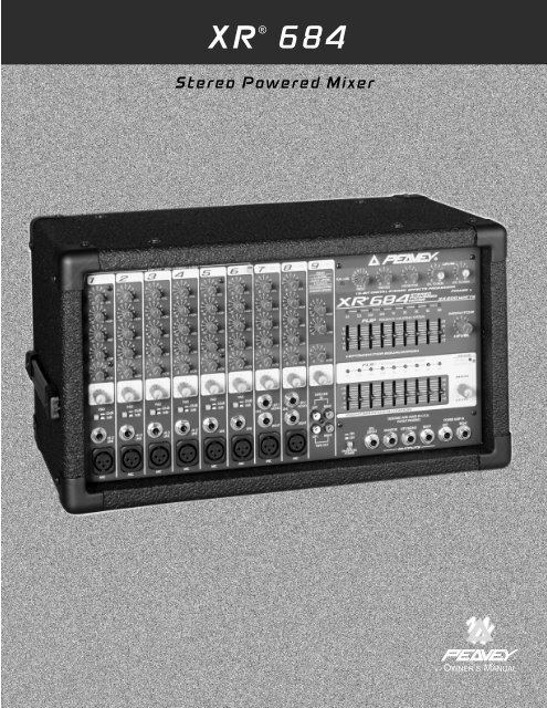
XR ® 684<br />
<strong>Stereo</strong> <strong>Powered</strong> <strong>Mixer</strong><br />
OWNER’S MANUAL<br />
®
Intended to alert the user to the presence of uninsulated “dangerous voltage” within the product’s<br />
enclosure that may be of sufficient magnitude to constitute a risk of electric shock to persons.<br />
Intended to alert the user of the presence of important operating and maintenance (servicing)<br />
instructions in the literature ac<strong>com</strong>panying the product.<br />
CAUTION: Risk of electrical shock — DO NOT OPEN!<br />
CAUTION: To reduce the risk of electric shock, do not remove cover. No user serviceable parts inside. Refer<br />
servicing to qualified service personnel.<br />
WARNING: To prevent electrical shock or fire hazard, do not expose this appliance to rain or moisture. Before<br />
using this appliance, read the operating guide for further warnings.<br />
Este símbolo tiene el propósito, de alertar al usuario de la presencia de “(voltaje) peligroso” que no tiene<br />
aislamiento dentro de la caja del producto que puede tener una magnitud suficiente <strong>com</strong>o para constituir<br />
riesgo de corrientazo.<br />
Este símbolo tiene el propósito de alertar al usario de la presencia de instruccones importantes sobre la<br />
operación y mantenimiento en la literatura que viene con el producto.<br />
PRECAUCION: Riesgo de corrientazo — No abra.<br />
PRECAUCION: Para disminuír el riesgo de corrientazo, no abra la cubierta. No hay piezas adentro que el usario<br />
pueda reparar. Deje todo mantenimiento a los técnicos calificados.<br />
ADVERTENCIA: Para evitar corrientazos o peligro de incendio, no deje expuesto a la lluvia o humedad este<br />
aparato Antes de usar este aparato, Iea más advertencias en la guía de operación.<br />
Ce symbole est utilisé pur indiquer à l’utilisateur la présence à l’intérieur de ce produit de tension nonisolée<br />
dangereuse pouvant être d’intensité suffisante pour constituer un risque de choc électrique.<br />
Ce symbole est utilisé pour indiquer à l’utilisateur qu’il ou qu’elle trouvera d’importantes instructions sur<br />
l’utilisation et l’entretien (service) de l’appareil dans la littérature ac<strong>com</strong>pagnant le produit.<br />
ATTENTION: Risques de choc électrique — NE PAS OUVRIR!<br />
ATTENTION: Afin de réduire le risque de choc électrique, ne pas enlever le couvercle. Il ne se trouve à l’intérieur<br />
aucune pièce pouvant être reparée par l’utilisateur. Confier I’entretien à un personnel qualifié.<br />
AVERTISSEMENT: Afin de prévenir les risques de décharge électrique ou de feu, n’exposez pas cet appareil à la<br />
pluie ou à l’humidité. Avant d’utiliser cet appareil, lisez les avertissements supplémentaires situés dans le guide.<br />
Dieses Symbol soll den Anwender vor unisolierten gefährlichen Spannungen innerhalb des Gehäuses<br />
warnen, die von Ausreichender Stärke sind, um einen elektrischen Schlag verursachen zu können.<br />
Dieses Symbol soll den Benutzer auf wichtige Instruktionen in der Bedienungsanleitung aufmerksam<br />
machen, die Handhabung und Wartung des Produkts betreffen.<br />
VORSICHT: Risiko — Elektrischer Schlag! Nicht öffnen!<br />
VORSICHT: Um das Risiko eines elektrischen Schlages zu vermeiden, nicht die Abdeckung enfernen. Es befinden<br />
sich keine Teile darin, die vom Anwender repariert werden könnten. Reparaturen nur von qualifiziertem<br />
Fachpersonal durchführen lassen.<br />
ACHTUNG: Um einen elektrischen Schlag oder Feuergefahr zu vermeiden, sollte dieses Gerät nicht dem Regen<br />
oder Feuchtigkeit ausgesetzt werden. Vor Inbetriebnahme unbedingt die Bedienungsanleitung lesen.<br />
2
ENGLISH<br />
XR 684 <strong>Powered</strong> Sound Reinforcement Mixing Console<br />
Compiled By: Peter Ochello, Technical Writer, <strong>Peavey</strong> Electronics Corp.<br />
General Description:<br />
Congratulations on your purchase of the XR 684 powered mixer. Within one <strong>com</strong>pact unit, we<br />
have packed feature after feature, each displaying the latest technology available. Here are several<br />
features you will certainly want to notice:<br />
• 8 low-noise, low-Z mic preamps<br />
• 4 true high-Z 1/4" mic inputs<br />
• 3-band equalization (Channels 1-8)<br />
• Monitor send (each channel)<br />
• EFX send (Channels 1-8)<br />
• -25 dB pad (Channels 1-6)<br />
• Low-cut filter (Channels 1-6)<br />
• <strong>Stereo</strong> line inputs (Channels 7-9)<br />
• 16-bit, DSP-based stereo reverb/effects with two parameter controls<br />
• Two 9-band graphic EQs with FLS ® Feedback Locating System ®<br />
• 48 V phantom power<br />
• <strong>Stereo</strong>/Main-Monitor mode switch<br />
• 2x200 W @ 4 ohms internal power amplifier<br />
• 420 W @ 8 ohms in bridge mode<br />
• DDT speaker protection<br />
The standard channels (1-4) feature discrete low noise mic preamps with globally switched<br />
phantom power, true high-impedance 1/4" mic inputs, low-cut filters, and three-band EQs. Two<br />
additional channels (5-6) offer balanced XLR mic inputs and 1/4" line level inputs. Finally, there are<br />
three stereo channels (7-9) for tape, CD, or synth inputs.<br />
The master section features a unique graphic equalizer/power amp mode switch. Without patching,<br />
the XR 684 can be used as a full stereo mixer amplifier (default). In the Main/Monitor mode, one<br />
graphic and amplifier can be used for monitor and the other graphic and amplifier for the main L & R<br />
(mono) signal.<br />
Also included in the master section are 16 stereo digital effects from the award winning Deltafex <br />
digital signal processor. By including separate Time/Size and Color/Tone controls, the user can<br />
create many effect settings from the 16 we provided. All channels, except Channel 9, have a dedicated<br />
digital effects send routed directly to the DSP effects processor.<br />
To take advantage of the XR 684’s powerful features, please read this owner’s manual carefully<br />
and keep it as a reference. This manual includes several sections detailing individual areas of mixer<br />
operation, including: control functions, set-up, and applications in sound reinforcement.<br />
3
CHANNEL SECTION:<br />
CHANNELS 1-4<br />
1. MIC INPUT: XLR balanced, low-impedance channel input optimized for a<br />
microphone or other low-level source. Pin 2 is the positive input. Because of the<br />
wide range of gain adjustment, signal levels as high as +10 dBV (2.45 V RMS)<br />
can be ac<strong>com</strong>modated. When the phantom power is enabled, this connector<br />
has +48 V on pins 2 and 3 with pin 1 as the ground reference. (The Mic Input<br />
can also be found on channels 5 through 8.)<br />
2. HI-Z/LINE INPUT: 1/4" balanced TRS high-impedance input. The tip is the<br />
positive input, which can also be used for unbalanced inputs. A Pad (#3) switch<br />
is provided to attenuate strong signals present at this input. Within the same<br />
channel, the mic input and the Hi-Z/Line input cannot be used simultaneously.<br />
3. PAD: Attenuates the input signal by 25 dB. If you find that barely touching<br />
the Level control (#4) gives you an enormous increase in volume or if distortion<br />
occurs, try using the Pad switch. In addition to increasing the dynamic range,<br />
the channel input can now ac<strong>com</strong>modate a higher input level before clipping.<br />
This may be necessary with a close mic on loud guitar amplifiers or drum kits.<br />
(The Pad switch can also be found on channels 5 and 6).<br />
4. LEVEL: Sets the signal level sent to the Left and Right bus. (The level<br />
control can also be found on channels 5 through 9.)<br />
5. MON: Adjusts the level of the channel signal (pre-EQ) that is added to the<br />
Monitor mix. (The Monitor control can also be found on channels 5 through 9.)<br />
This control is independent of the main channel level control (#4).<br />
9<br />
8<br />
7<br />
6<br />
5<br />
4<br />
6. LOW EQ: A shelving type of active tone control that varies the bass<br />
frequency levels ±15 dB at 70 Hz. It will add depth to thin signals, or clean up<br />
muddy ones. (The low control can also be found on channels 5 through 9.)<br />
7. MID EQ: Mid ±15 dB. This control sets the amount of cut and boost at the<br />
mid-frequency. (The mid control can also be found on channels 5 through 8.)<br />
8. HIGH EQ: A shelving type of active tone control that varies the treble<br />
frequency levels ±15 dB at 12 kHz. It is designed to remove noise or to add brilliance<br />
to the signal, depending on the quality of the source. (The high control<br />
can also be found on channels 5 through 9.)<br />
9. EFX: This control varies the level into the digital effects processor bus<br />
adjusting the signal level from the particular channel to the digital processor.<br />
(The effects control can also be found on channels 5 through 8.) The channel<br />
level control (#4) also affects this level.<br />
3<br />
2<br />
1<br />
4
NOTE: Channels 5-9 contain features that differ from the previous channels.<br />
Only those features are mentioned below. For information on features not<br />
mentioned please refer to the section for Channels 1-4.<br />
CHANNELS 5-6<br />
10. LINE: 1/4" balanced TRS input for line level signals. This signal is connected<br />
through a 25 dB pad to the mic input below it.<br />
11<br />
11. LOW CUT: This is a low-cut filter with a corner frequency of 80 Hz used to<br />
filter rumble, wind noise, breath thumps, stage noise, and other low-frequency<br />
<strong>com</strong>ponents that rob power from the amplifiers and muddy the signal. Depressing<br />
this switch will affect channels 1-6 only. Use of the filter will not affect the Monitor<br />
signal.<br />
CHANNELS 7-8<br />
12. RIGHT INPUT: High-impedance 1/4" input for line-level signals. The Right<br />
Input is adjusted by the Level control (#4). The signal is then routed to the internal<br />
power amp. If the XR 684 is in Left/Right mode then the signal will go to the Right<br />
Speaker Output (#37). In Mon/Main mode the signal is <strong>com</strong>bined with the Left<br />
and placed on the Main Speaker Output. The right signal can also be patched out<br />
of the XR 684 via the Right Output jack (#31) to external <strong>com</strong>ponents such as<br />
effects, power amps, and recording devices.<br />
13. LEFT/MONO INPUT: High-impedance 1/4" input for line-level signals. The<br />
Left/Mono input supplies signal to both the Left and Right channels (if there is<br />
nothing inserted to the right input jack) through the Level control (#4). In<br />
Left/Right mode the signal will go to the Left Speaker Output (and Right Speaker<br />
Output if nothing is inserted to the right input jack). In Mon/Main mode the signal<br />
is <strong>com</strong>bined with the Right and placed on the Main Speaker Output.<br />
13<br />
12<br />
10<br />
CHANNEL 9<br />
14. TAPE IN: This stereo RCA phono jack accepts a stereo input (nominally<br />
-10 dBV) from the output of a tape deck or CD player and places it on the Left<br />
and Right channels as well as the Monitor Mix.<br />
15. TAPE OUT: This stereo RCA phono jack provides a signal for the recording<br />
inputs of a stereo tape deck.<br />
CAUTION: DO NOT HOOK THE TAPE IN AND TAPE OUT TO THE INPUT AND<br />
OUTPUT OF THE SAME DECK. DOING SO WILL FORM A LOOP<br />
CAUSING SEVERE FEEDBACK. USE SEPERATE DECKS FOR<br />
RECORDING AND PLAYBACK.<br />
MASTER SECTION:<br />
16. EFFECTS PEAK LED: Illuminates to indicate -6 dB of headroom before the<br />
signals being sent to the effects circuit are clipped. Ideally, you would want this<br />
LED to light only occassionally if at all. An occassional blink indicates that you<br />
have the levels at an optimum setting. It is advisable to listen carefully to the<br />
output at the same time in order to determine the final setting.<br />
14<br />
15<br />
5
17. PRESET: Selects the effect preset from the list below.<br />
EFX Presets<br />
PRESET NAME TIME/SIZE COLOR/TONE<br />
1 Chamber Time: 150 to 5,000 ms Damping (High Frequency)<br />
2 Plate Time: 100 to 4,000 ms Damping (High Frequency)<br />
3 Room Time: 150 to 5,000 ms Damping (High Frequency)<br />
4 Cathedral Time: 100 to 8,000 ms Damping (High Frequency)<br />
5 Spring Time: 150 to 5,000 ms Damping (High Frequency)<br />
6 Gate Time: 150 to 500 ms Damping (High Frequency)<br />
7 Reverse Time: 150 to 500 ms Damping (High Frequency)<br />
8 Delay + Reverb Time: 0 to 225 ms Reverb Time: 0 to 5,000 ms<br />
9 Bright Delay Time: 0 to 500 ms Feedback: 0 to 99%<br />
10 Warm Delay Time: 0 to 500 ms Feedback: 0 to 99%<br />
11 Dark Delay Time: 0 to 500 ms Feedback: 0 to 99%<br />
12 Ping Pong Delay Time: 0 to 500 ms Feedback: 0 to 99%<br />
13 Chorus Rate: 0.125 to 8 Hz Depth: Best Set Full CW<br />
14 Phaser Rate: 0.250 to 16 Hz Depth: Best Set Full CW<br />
15 Flange Rate: 0.10 to 2.5 Hz Depth: Best Set Full CW<br />
16 Rotary Speaker High Speed: 0.50 to 25 Hz Width: 0 to 100% CW<br />
18. TIME/SIZE: In Reverb and Delay presets, this control adjusts the time of the particular reverb or delay;<br />
in Chorus, Phaser, and Flange, it adjusts the rate of each. In Rotary Speaker setting, this adjusts the speed<br />
of the speaker rotation.<br />
19. COLOR/TONE: Adjusts the high-frequency content of the effects signal. (While using a delay this<br />
control adjusts the feedback or depth.)<br />
20. EFX TO MON: Controls the amount of effects signal sent to the monitor mix. This control allows effects<br />
to be heard from the stage via the monitor.<br />
21. EFX TO MAIN: Controls the amount of effects signal sent to the main mix.<br />
22. FLS ® (Feedback Locator System ® ): These LEDs illuminate to indicate the frequency band of highest<br />
energy. When feedback occurs, this system will automatically indicate the graphics slider to use to decrease<br />
that frequency band’s gain in order to lessen or eliminate feedback. (NOTE: These LEDs illuminate with any<br />
audio signal, not just during feedback.)<br />
23. GRAPHIC EQUALIZERS: These nine-band equalizers are fixed on one-octave centers. They are<br />
designed for 12 dB of cut and 12 dB boost. They are connected directly to their power amplifier inputs.<br />
24. SYSTEM MODE: This switch is used to configure the XR 684 as either a stereo or dual mono amplifier.<br />
It is recessed to prevent accidental switching during a performance. Use a non-metallic object to change the<br />
switch position (e.g., a toothpick). The XR 684 is shipped from the factory in the default setting of Left Main to<br />
the upper EQ and Right to the lower EQ. When this switch is depressed it switches the lower EQ to (mono)<br />
PA Left + Right. The upper EQ then be<strong>com</strong>es the monitor signal only, creating an entire PA and monitor mixing<br />
system in one small, easy-to-carry package. And this change is ac<strong>com</strong>plished without a single patch cord!<br />
25. MONITOR LEVEL: Sets the overall level of the monitor signal that is sent to the Monitor Output Jack.<br />
This control also sets the monitor level going to the power amp when in Main/Monitor mode (see System<br />
Mode #24).<br />
6
17<br />
18<br />
19<br />
20<br />
21<br />
16<br />
33<br />
23<br />
22<br />
25<br />
24<br />
22<br />
26<br />
23<br />
27<br />
28<br />
29<br />
30<br />
31<br />
32<br />
26. MAIN LEVEL: This is the master level control for the main mix sent to the Left/Mono and Right output<br />
jacks. This control sets the Main level going to the power amp when in Main/Monitor mode (see System<br />
Mode #24). A good starting position for this control is the center detent position (12:00).<br />
27. PHANTOM POWER SWITCH: Applies 48 V DC voltage to all input XLR connectors to power microphones<br />
that require it.<br />
CAUTION! When phantom power is switched on, make sure that any channel you are plugging a mic into is<br />
turned down in both the main and monitor mixes. Otherwise, there will be a loud pop in the PA. This is<br />
normal. It is best to plug all mics into their respective channels with the phantom power switched off.<br />
This reduces noise in the PA and reduces the chances of the mic being damaged. If phantom power is used,<br />
do not connect unbalanced microphones or other devices that cannot handle this voltage to the XLR inputs.<br />
(Some wireless receivers may be damaged; consult their manuals for <strong>com</strong>patibility.) The line input 1/4" jacks<br />
are not connected to the phantom supply, and are safe for all inputs (balanced or unbalanced). An unbalanced-to-balanced<br />
impedance converter, such as the <strong>Peavey</strong> 5116 or a <strong>Peavey</strong> 1:1 Interface Adapter, can<br />
also be used to isolate a mic from phantom voltage.<br />
28. EFX DEFEAT: This 1/4" jack accepts an on/off 1/4" footswitch (<strong>Peavey</strong> Pt. #00051000) to defeat the<br />
effects of both the Main and Monitor mixes.<br />
29. MONITOR OUTPUT: This 1/4" jack provides an output from the monitor mix to supply external power<br />
amp/monitor <strong>com</strong>binations. The level of this signal is determined by the Monitor Level control.<br />
7
30. LEFT/MONO OUTPUT: This 1/4" jack provides an output from the Left Main mix to supply external<br />
amp/speaker <strong>com</strong>binations. The level of this signal is determined by the Main Level control. When no plug is<br />
connected to the Right Output (#31) then the right signal is mixed with the left, and both can be accessed at<br />
the Left/Mono Output. This works well when you use the internal amps for monitor and external amps for<br />
Main. Only one patch cord is required to get the Main out to the external amp.<br />
31. RIGHT OUTPUT: This 1/4" jack provides an output from the Right Main mix to supply external<br />
amp/speaker <strong>com</strong>binations. The level of this signal is determined by the Main Level control.<br />
32. POWER AMP INPUTS: Plugging into these jacks allows the user to go directly into the Graphic<br />
Equalizer, then into its respective power amplifier channel.<br />
33. POWER LED: The power on LED indicator will light when the unit is powered.<br />
AC POWER AND POWER AMPLIFIER SECTION:<br />
34. A/C POWER INLET: This is the receptacle for an IEC line cord, which provides AC power to the<br />
mixer/amplifier. Connect the line cord to this connector to provide power to the unit. Damage to the<br />
equipment may result if improper line voltage is used (see line voltage marking on unit).<br />
35. POWER: The mixer’s main power switch. The power on LED indicator (#33) will light when the unit is<br />
powered.<br />
36. FUSE: This is the main safety fuse for the AC line voltage. Only<br />
replace the fuse with one the exact same type and rating. IF THE<br />
FUSE CONTINUES TO OPEN, DO NOT OVER FUSE. TAKE<br />
THE UNIT TO AN AUTHORIZED PEAVEY SERVICE CENTER!<br />
34 36 35<br />
37. PARALLEL LEFT/RIGHT SPEAKER OUTPUTS: These 1/4" jacks<br />
are the amplifier’s output. By connecting a speaker cable to this<br />
jack and to a speaker cabinet, you <strong>com</strong>plete the signal chain. You<br />
will notice that there are two pairs of jacks with another jack in the<br />
middle. The two pairs are your two (stereo) amp outputs. Two cabinets<br />
can be connected to each channel, as long as the <strong>com</strong>bined impedance<br />
of the cabinets is not less than 4 ohms. (i.e., two 8 ohms cabinets in<br />
parallel = 4 ohms, four 16 ohms speakers in parallel = 4 ohms, etc.).<br />
38. BRIDGE OUTPUT: The bridge output of the XR 684 allows the<br />
power of the left and right amplifiers to be <strong>com</strong>bined into one mono<br />
output in applications where only one speaker will be used. To use the<br />
bridge output, the system mode switch must be in the Left/Right<br />
position. Connect an 8 ohm minimum impedance speaker to the center<br />
bridge output jack.<br />
37 38 37<br />
CAUTION: When using the bridge output no other speakers should be connected to the adjacent parallel<br />
speaker outputs. In addition, the minimum load for the XR 684 in bridge mode is 8 ohms. Do not allow<br />
the total impedance to drop below 8 ohms or serious damage to the amplifier may occur.<br />
8
XR ® 684 BLOCK DIAGRAM<br />
CHANNELS 1-4<br />
HI-Z INPUT MIC PREAMP<br />
TONE CONTROL<br />
LO MIDHI<br />
Effect Defeat<br />
+48V PHANTON<br />
LO-Z INPUT<br />
PAD<br />
CHANNEL GAIN<br />
EFX LEVEL<br />
<strong>Stereo</strong><br />
Digital<br />
Effects<br />
Time Color<br />
Effects to Main<br />
CHANNELS 5-6<br />
LINE INPUT MIC PREAMP<br />
MONITOR SEND<br />
TONE CONTROL<br />
LO M I D HI<br />
Peak<br />
LED<br />
Effects<br />
Selector<br />
+48V PHANTON<br />
LO-Z INPUT<br />
CHANNEL GAIN<br />
EFX LEVEL<br />
Effects to<br />
Monitor<br />
Tape Out<br />
MONITOR SEND<br />
Left/Mono Main Output<br />
CHANNELS 7-8<br />
STEREO LINE INPUT<br />
TONE CONTROL<br />
LO M I D HI<br />
Mode Select<br />
Left Power Amp Input<br />
LEFT/<br />
MONO<br />
EFX LEVEL<br />
CHANNEL GAIN<br />
Right Power Amp Input<br />
RIGHT<br />
+48V PHANTON<br />
LO-Z INPUT<br />
MIC PREAMP<br />
LO M I D HI<br />
Mon Send<br />
Right Main Output<br />
TAPE/CD<br />
INPUT<br />
CHANNEL 9 (TAPE)<br />
TONE CONTROL<br />
LO HI<br />
Monitor<br />
Master<br />
Monitor Output<br />
CHANNEL GAIN<br />
LO HI<br />
Monitor Send Low Cut<br />
(80 Hz)<br />
Left/Monitor<br />
Right/Main<br />
DDT<br />
Power Amp<br />
Left/Monitor<br />
Power Amp Out<br />
DDT<br />
Bridge Out<br />
Power Amp<br />
Left/Monitor<br />
Power Amp Out<br />
210 WATTS PER CHANNEL • 4 OHMS<br />
150 WATTS PER CHANNEL • 8 OHMS<br />
BRIDGE 420 WATTS • 8 OHMS<br />
1-6 BUS<br />
MON BUS<br />
EFX BUS<br />
LEFT BUS<br />
RIGHT BUS<br />
PAD<br />
9
INPUTS<br />
HI-Z<br />
(W/PAD) LINE/TAPE<br />
LO-Z MIC<br />
(W/PAD)<br />
LO-Z MIC<br />
(NO PAD)<br />
HI-Z MIC<br />
(NO PAD)<br />
+30<br />
+20<br />
+10<br />
0 dBu<br />
-10<br />
-20<br />
-30<br />
-40<br />
-50<br />
-60<br />
+21 dBu<br />
+13.5 dBu<br />
-11 dBu<br />
-12.5 dBu<br />
-28 dBu<br />
-35 dBu<br />
-60 dBu<br />
XR ® 684 LEVEL DIAGRAM<br />
®<br />
XR 684 LEVELS<br />
EQ<br />
+15 dB<br />
MONITOR OUT LEFT & RIGHT OUT<br />
+22 dBu MAX<br />
+22 dBu MAX<br />
TAPE OUT<br />
+10 dBV MAX<br />
2 dBu = 0 dBV<br />
-15 dB<br />
-10 dBV NOM.<br />
GRAPHIC EQ<br />
+12 dB<br />
TO POWER AMPS<br />
+ 2 dBu NOMINAL<br />
-12 dB<br />
10
XR ® 684 IN - LEFT/RIGHT MODE<br />
XR ® 684 In - Left/Right Mode<br />
Mains - Left<br />
Mains - Right<br />
Impulse 200 Impulse 200<br />
Left/Monitor Outputs (Rear)<br />
Right/Main Outputs (Rear)<br />
Mode<br />
Switch<br />
Out<br />
Reactor ® Tape Player<br />
Out<br />
PVM 22<br />
MAQ 150<br />
Hi-Z Mic<br />
Wireless<br />
Mic/Gtr<br />
Tape Player In<br />
Keyboard<br />
L<br />
R<br />
<strong>Stereo</strong> Voice Module<br />
SP 112M<br />
11
XR ® 684 IN - MONITOR/MAIN MODE<br />
XR ® 684 In - Monitor/Main Mode<br />
Monitors<br />
SP 112M<br />
Mains<br />
Impulse 200<br />
Left/Monitor Outputs (Rear)<br />
Right/Main Outputs (Rear)<br />
Mode<br />
Switch<br />
Depressed<br />
(In)<br />
Reactor ®<br />
Tape Player<br />
Out<br />
PVM 22<br />
Hi-Z Mic<br />
Wireless<br />
Mic/Gtr<br />
Tape Player In<br />
Keyboard<br />
L<br />
R<br />
<strong>Stereo</strong> Voice Module<br />
12
Specifications:<br />
XR 684<br />
Input Specifications:<br />
Function Input Z Input Gains Input Levels Bal/ Connector<br />
(ohms) control Min** Nominal* Max UnBal.<br />
Min setting<br />
Lo-Z 2 k Max w/o pad -60 dBu -30 dBu -11 dBu Bal. XLR: Pin 1 Gnd,<br />
(150 ohms) (50 dB) Pin 2 (+), Pin 3 (-)<br />
Channel 1-8 Max. w/pad -35 dBu -5 dBu +13.5 dBu<br />
(25 dB)<br />
Hi-Z 100 k Max w/o pad -60 dBu -30 dBu -12 dBu Bal. 1/4" TRS: Tip (+),<br />
(50 dB) Ring (-),<br />
Sleeve Ground<br />
Channel 1-4 Max w/pad -35 dBu -5 dBu +12.5 dBu<br />
(25 dB)<br />
Line Input 22 k Max. w/o pad -28 dBu +2 dBu +21 dBu Unbal. 1/4" TRS: Tip Send,<br />
(30 dB) Ring Return,<br />
Channel 5-8 Max. w/pad -3 dBu +27 dBu +46 dBu Sleeve Ground<br />
(5 dB)<br />
Tape 20 k Max. Gain -28 dBu +2 dBu +21 dBu Unbal. RCA Jacks<br />
Channel 9<br />
(30 dB)<br />
0 dBV=1V (RMS)<br />
** Min input level (sensitivity) is the smallest signal that will produce nominal output (2 dBu) with channel and master<br />
level controls set for maximum gain.<br />
* Nominal settings are defined as all controls set a 0 dB (or 50% rotation for rotary pots)<br />
XR 684 Output Specifications:<br />
Function Minimum Load Z Output Level Bal./Unbal. Connector<br />
(ohms)<br />
Nominal Max.<br />
Main L/R600 +2 dBu +21 dbu Unbal. 1/4" Phono Tip (+),<br />
Sleeve Ground<br />
Monitor 600 +2 dBu +21 dBu Unbal. 1/4" Phono Tip (+),<br />
Sleeve Ground<br />
Tape 10 k -10 dBu +10 dBu Unbal. RCA<br />
+2 dBu = 0 dBV = 1V (RMS)<br />
Gain:<br />
Mic Input to L and R Output<br />
Hi-Z Input to L and R Output<br />
Line Input to L and R Output<br />
60 dB (Max. Gain)<br />
60 dB (Max. Gain)<br />
30 dB (Max. Gain)<br />
13
Frequency Response:<br />
Mic Input to L - R Output<br />
Line Input to L - R Output<br />
To Power Amplifier Output<br />
20 Hz — 20 kHz +0 dB/-1 dB<br />
20 Hz — 20 kHz +0 dB/-1 dB<br />
20 Hz — 20 kHz +0 dB/-1 dB<br />
Total Harmonic Distortion (THD):<br />
< 0.01% 20 Hz — 20 kHz mic input to L/R mon. output at nominal level (20 Hz — 80 kHz BW)<br />
< 0.01% 20 Hz — 20 kHz line input to L/R output at output at nominal level (20 Hz — 80 kHz BW)<br />
< .005% Typical at 1 kHz<br />
Graphic Equalizer:<br />
Filter Bandwidth<br />
Filter Frequencies<br />
Maximum Boost and Cut<br />
1 octave<br />
63, 125, 250, 500 1 k, 2 k, 4 k, 8 k, 16 k<br />
+12 dB Boost, -12 dB Cut<br />
XR 684 Hum and Noise:<br />
Output Residual Noise S/N Ratio Test Conditions<br />
Ref: 0 dBu<br />
Ref: 2 dBu<br />
Main Left -98 dBu -100 dB All controls down<br />
and Right<br />
-89 dBu -91 dB One channel nominal, master<br />
nominal<br />
-81 dBu -83 dB Master level nominal,<br />
Channel level nominal, Mic<br />
Inputs terminated @ 150 ohms<br />
Monitor -96 dBu -98 dB All controls down<br />
-90 dBu -92 dB One channel nominal, master<br />
nominal<br />
-81 dBu -83 dB Master level nominal,<br />
Channel level nominal, Mic<br />
Inputs terminated @ 150 ohms<br />
(Hum and noise measurements: 22 Hz to 22 kHz BW)<br />
S/N Ratio:<br />
> 85 dB below rated output (200 W/channel), mic/line to speaker output<br />
Equivalent Input Noise (EIN):<br />
-121.5 dBu (Input terminated with 150 ohms)<br />
Crosstalk:<br />
> 80 dB Adjacent Input Channels (20 Hz — 20 kHz)<br />
> 70 dB Left to right outputs (20 Hz — 20 kHz)<br />
Common Mode Rejection Ratio (Mic Input):<br />
50 dB min. (20 Hz - 20 kHz)<br />
60 dB typical @ 1 kHz<br />
14
XR 684/400 SC AMPLIFIER SPECIFICATIONS<br />
POWER SECTION<br />
(400 SC Module with DDT )<br />
Frequency Response:<br />
+0, -1 dB, 20 Hz — 20 kHz @ rated power<br />
Rated Power:<br />
• 210 watts RMS into 4 ohms, both channels<br />
driven<br />
• 150 watts RMS into 8 ohms, both channels<br />
driven<br />
• Bridge out 420 watts into 8 ohms*<br />
*8 ohms minimum load for bridge output only<br />
Total Harmonic Distortion:<br />
Less than .01% @ 1 kHz @ rated power<br />
DDT Dynamic Range:<br />
Greater than 26 dB<br />
DDT Maximum Distortion:<br />
Below 0.5% THD for 6 dB overload<br />
Below 1% THD for 20 dB overload<br />
Hum and Noise:<br />
-97 dB below 210 watts<br />
Damping Factor:<br />
Greater than 100 @ 1 kHz, 4 ohms<br />
Input Sensitivity:<br />
1.5 V RMS for 210 watts @ 4 ohms<br />
Input Impedance:<br />
2 k ohms<br />
Power Requirements:<br />
600 watts, 120 V AC, 60 Hz<br />
Dimensions:<br />
Width: 19.125"<br />
Height: 10.875"<br />
Depth: 11.0"<br />
Weight: 35.6 lbs.<br />
15
ESPAÑOL<br />
Consola mezcladora reforzadora de sonido con amplificador XR 684<br />
Descripción General:<br />
Felicitaciones por su <strong>com</strong>pra de la consola mezcladora con amplificador XR 684. En una unidad<br />
<strong>com</strong>pacta hemos incluido múltiples características, cada una de las cuales ofrece la última tecnología<br />
disponible. A continuación enumeramos algunas de estas características que, por cierto, llamarán<br />
su atención:<br />
• Ocho preamplificadores de micrófono de bajo ruido y baja impedancia<br />
• Cuatro entradas para micrófono de alta impedancia verdadera de 1/4 pulg.<br />
• Ecualización de tres bandas (canales 1 a 8)<br />
• Señal de muestra al monitor (para cada canal)<br />
• Señal de muestra de efectos (EFX) (canales 1 a 8)<br />
• Atenuador de –25 dB (canales 1 a 6)<br />
• Filtro de corte de baja frecuencia (canales 1 a 6)<br />
• Entradas de línea estereofónicas (canales 7 a 9)<br />
• Reverberación/efectos estereofónicos de 16 bits basados en un procesador de señales digitales<br />
(DSP) con controles para dos parámetros<br />
• Dos ecualizadores gráficos de nueve bandas con FLS ® (sistema localizador de retroalimentación)<br />
• Alimentación fantasma de 48 V<br />
• Conmutador de modo estereofónico principal/monitor<br />
• Amplificador de potencia interno de 2 x 200 W a 4 Ω<br />
• 420 W a 8 Ω en el modo de puente<br />
• Protección de altavoces DDT (técnica de detección de distorsión)<br />
Los canales estándar (1 a 4) tienen las siguientes características: preamplificadores de micrófono<br />
discretos con alimentación fantasma conmutada globalmente, entradas de micrófono de 1/4 pulg.<br />
con alta impedancia verdadera, filtros de corte de baja frecuencia y ecualizadores de tres bandas.<br />
Dos canales adicionales (5 y 6) tienen entradas balanceadas de micrófono XLR y de nivel de línea<br />
de 1/4 pulg. Por último, hay tres canales estereofónicos (7 a 9) para entradas de cinta, CD o sintetizador.<br />
La sección maestra cuenta con un exclusivo conmutador de modo ecualizador gráfico/amplificador<br />
de potencia. El XR 684 no necesita conexiones y puede emplearse <strong>com</strong>o amplificador estereofónico<br />
<strong>com</strong>pleto (configuración por defecto). En el modo de monitor/principal, un ecualizador gráfico y un<br />
amplificador pueden emplearse para la señal del monitor y el otro ecualizador gráfico y amplificador<br />
para la señal principal derecha e izquierda (monoaural).<br />
En la sección maestra también se incluyen 16 efectos digitales correspondientes al destacado<br />
procesador digital de señales Deltafex . Al incluirse controles separados para tiempo/tamaño y<br />
color/tono, el usuario puede crear muchas configuraciones de efectos a partir de las 16 provistas.<br />
Todos los canales, excepto el Canal 9, tienen una señal digital dedicada de muestra de efectos,<br />
conectada directamente al procesador de efectos DSP.<br />
Para aprovechar las poderosas características del XR 684, lea atentamente este manual del propietario<br />
y guárdelo <strong>com</strong>o referencia. El manual incluye varias secciones que detallan zonas individuales<br />
para la operación del mezclador, tales <strong>com</strong>o funciones de los controles, configuración y aplicaciones<br />
del refuerzo de sonido.<br />
16
Consulte los diagramas del panel delantero<br />
en la sección de inglés de est manual.<br />
SECCIÓN DE CANALES:<br />
CANALES 1 A 4<br />
1. ENTRADA DE MICRÓFONO: Entrada de canal de baja impedancia con conector XRL equilibrado, optimizada<br />
para un micrófono u otra fuente de bajo nivel. El terminal 2 es la entrada positiva. En razón de la<br />
amplia gama de ajuste de la ganancia, se pueden recibir niveles de señal de hasta +10 dBV (2,45 Vef).<br />
Cuando se habilita la alimentación fantasma, este conector tiene +48 V en los terminales 2 y 3, con el terminal<br />
1 <strong>com</strong>o referencia de tierra. (La entrada de micrófono también se puede utilizar con los canales 5 a 8.)<br />
2. ENTRADA DE LÍNEA DE ALTA IMPEDANCIA: Entrada de alta impedancia (> 200 kΩ) TRS equilibrada<br />
de 1/4 pulg. La punta es la entrada positiva, que también puede utilizarse para entradas no balanceadas. Se<br />
provee un conmutador atenuador (Nº 3) para atenuar las señales intensas presentes en esta entrada. Dentro<br />
del mismo canal no pueden utilizarse simultáneamente las entradas de micrófono y de línea de alta impedancia.<br />
3. ATENUADOR: Atenúa la señal de entrada en 25 dB. Si usted nota que el volumen aumenta desmedidamente<br />
al modificar el control de nivel (Nº 4) o si se produce distorsión, intente emplear el conmutador del<br />
atenuador. Además de incrementar el rango dinámico, la entrada de canal puede recibir un nivel de entrada<br />
más alto antes de producir el recorte de la señal. Esto puede ser necesario con un micrófono cercano a un<br />
amplificador de guitarra fuerte o a una batería de percusión. (El conmutador del atenuador también se puede<br />
utilizar con los canales 5 y 6.)<br />
4. NIVEL: Configura el nivel de la señal enviada al bus izquierdo y al bus derecho. (El control de nivel también<br />
se puede utilizar los canales 5 a 9.)<br />
5. Monitor: Ajusta el nivel de la señal del canal (antes de la ecualización) que se agrega a la mezcla del<br />
monitor. (Los canales 5 a 9 también cuentan con control de monitor.) Este control es independiente del control<br />
principal de nivel del canal (Nº 4).<br />
6. ECUALIZADOR DE GRAVES: Es un control de tono activo del tipo de variación continua, que modifica<br />
los niveles de las frecuencias bajas en ±15 dB a 70 Hz. Añade profundidad a las señales limpias o limpia las<br />
señales sucias. (Los canales 5 a 9 también cuentan con control de graves.)<br />
7. ECUALIZADOR DE SONIDOS MEDIOS: Nivel de las frecuencias medias ±15 dB. Este control configura<br />
la cantidad de recorte o refuerzo de las frecuencias medias. (Los canales 5 a 8 también cuentan con control<br />
de sonidos medios.)<br />
8. ECUALIZACIÓN DE AGUDOS: Es un control de tono activo del tipo de variación continua que modifica<br />
los niveles de las frecuencias altas en ±15 dB a 12 kHz. Está diseñado para quitar el ruido de la señal o<br />
agregarle brillo, según la calidad de la fuente. (Los canales 5 a 9 también cuentan con control de agudos.)<br />
9. EFECTOS: Este control varía el nivel en el bus del procesador de efectos digitales, ajustando el nivel de<br />
la señal de un canal particular al procesador digital. (Los canales 5 a 8 también cuentan con control de efectos.)<br />
El control principal de nivel del canal (Nº 4) también afecta este nivel.<br />
NOTA: Los canales 5 a 9 tienen características diferentes de los canales 1 a 4. A continuación, sólo se mencionan<br />
dichas características. Para obtener información sobre las características no mencionadas, sírvase<br />
consultar la sección de los canales 1 a 4.<br />
CANALES 5 Y 6<br />
10. LÍNEA: Entrada de 1/4 pulg. TRS equilibrada, para señales con nivel de línea. Esta señal se conecta a<br />
la entrada de micrófono situada debajo de la misma a través de un atenuador de 25 dB.<br />
17
11. CORTE DE BAJA FRECUENCIA: Es un filtro de corte de baja frecuencia con una frecuencia de transición<br />
de 80 Hz, que se utiliza para filtrar ruidos de bandeja giradiscos, viento, soplidos, ruido de fondo y otros<br />
<strong>com</strong>ponentes de baja frecuencia que quitan potencia a los amplificadores y ensucian la señal. Al oprimir este<br />
conmutador, se afecta sólo a los canales 1 a 6. El empleo del filtro no afecta la señal de monitor.<br />
CANALES 7 Y 8<br />
12. ENTRADA DERECHA: Entrada de alta impedancia de 1/4 pulg. para señales con nivel de línea. La<br />
entrada derecha se ajusta con el control de nivel (Nº 4). La señal es conducida luego al amplificador de<br />
potencia interno. Si el XR 684 está en el modo izquierdo/derecho, la señal se envía a la salida al altavoz<br />
derecho (Nº 37). En el modo de monitor/principal, la señal se <strong>com</strong>bina con el canal izquierdo y se envía a la<br />
salida de altavoces principal. La señal derecha se puede tomar del XR 684 para enviarla a <strong>com</strong>ponentes<br />
externos, tales <strong>com</strong>o efectos, amplificadores de potencia y dispositivos de grabación, mediante una conexión<br />
temporal con el enchufe hembra de la salida derecha (Nº 31).<br />
13. ENTRADA IZQUIERDA/MONOAURAL: Entrada de alta impedancia de 1/4 pulg. para señales con nivel<br />
de línea. La entrada izquierda/monoaural suministra señal a ambos canales izquierdo y derecho (si no hay<br />
ningún <strong>com</strong>ponente conectado al enchufe hembra derecho) a través del control de nivel (Nº 4). En el modo<br />
izquierdo/monoaural, la señal se envía a la salida al altavoz izquierdo (y a la salida al altavoz derecho, si no<br />
hay ningún <strong>com</strong>ponente conectado al enchufe hembra de la entrada derecha). En el modo de monitor/principal,<br />
la señal se <strong>com</strong>bina con la señal derecha y se envía a la salida principal de altavoces.<br />
CANAL 9<br />
14. ENTRADA DE CINTA: Este enchufe hembra fonográfico estereofónico tipo RCA acepta la entrada<br />
estereofónica (nominalmente de –10 dBV) de la salida de un grabador de cinta o de un reproductor de CD y<br />
la envía a los canales izquierdo y derecho, así <strong>com</strong>o a la mezcla de monitor.<br />
15. SALIDA PARA CINTA: Este enchufe hembra fonográfico estereofónico tipo RCA provee señal a las<br />
entradas para grabación en un grabador de cinta estereofónico.<br />
PRECAUCIÓN: NO CONECTE LA ENTRADA DE CINTA Y LA SALIDA PARA CINTA A LA ENTRADA Y A LA<br />
SALIDA DEL MISMO GRABADOR DE CINTA. SI LO HACE, SE FORMA UN CIRCUITO REALI-<br />
MENTADO QUE CAUSA UNA RETROALIMENTACIÓN MUY INTENSA. UTILICE GRABADORES<br />
DE CINTA SEPARADOS PARA LA GRABACIÓN Y LA REPRODUCCIÓN.<br />
SECCIÓN MAESTRA<br />
16. LED INDICADOR DE PICO DE EFECTOS: Se enciende para indicar que hay una tolerancia de –6 dB<br />
del máximo nivel antes de que las señales enviadas al circuito de efectos sean recortadas. Idealmente, este<br />
LED indicador sólo debe iluminarse ocasionalmente. Un destello ocasional indica que los niveles tienen una<br />
configuración óptima. A fin de determinar la configuración definitiva, es re<strong>com</strong>endable escuchar la salida<br />
simultáneamente.<br />
17. CONFIGURACIONES PREDETERMINADAS: Seleccione la configuración predeterminada de efectos<br />
entre las siguientes:<br />
18
Configuraciones predeterminadas de efectos<br />
PREDETERMINADA NOMBRE TIEMPO/DURACIÓN COLOR/TONO<br />
1 Cámara Tiempo: 150 a 5000 ms Amortiguamiento (altas frecuencias)<br />
2 Placa Tiempo: 100 a 4000 ms Amortiguamiento (altas frecuencias)<br />
3 Sala Tiempo: 150 a 5000 ms Amortiguamiento (altas frecuencias)<br />
4 Catedra Tiempo: 100 a 8000 ms Amortiguamiento (altas frecuencias)<br />
5 Elástico Tiempo: 150 a 5000 ms Amortiguamiento (altas frecuencias)<br />
6 Compuerta Tiempo: 150 a 500 ms Amortiguamiento (altas frecuencias)<br />
7 Inversión Tiempo: 150 a 500 ms Amortiguamiento (altas frecuencias)<br />
8 Retardo + Tiempo: 0 a 225 ms Tiempo de reverberación: 0 a 5000 ms<br />
reverberación<br />
9 Retardo brillante Tiempo: 0 a 500 ms Retroalimentación: 0 a 99%<br />
10 Retardo caliente Tiempo: 0 a 500 ms Retroalimentación: 0 a 99%<br />
11 Retardo obscuro Tiempo: 0 a 500 ms Retroalimentación: 0 a 99%<br />
12 Retardo ping-pong Tiempo: 0 a 500 ms Retroalimentación: 0 a 99%<br />
13 Coro Velocidad: 0,125 a 8 Hz Profundidad: Mejor configuración totalmente<br />
hacia la derecha<br />
14 Desfasador Velocidad: 0,250 a 16 Hz Profundidad: Mejor configuración totalmente<br />
hacia la derecha<br />
15 Realce Velocidad: 0,10 a 2,5 Hz Profundidad: Mejor configuración totalmente<br />
hacia la derecha<br />
16 Altavoz giratorio Alta velocidad: 0,50 a Ancho: 0 a 100% hacia la derecha<br />
25 Hz<br />
18. TIEMPO/TAMAÑO: En las configuraciones de reverberación y retardo, este control ajusta el<br />
tiempo de la reverberación o del retardo; en las configuraciones de coro, desfasador y realce, ajusta<br />
la velocidad de cada una. En la configuración de altavoz giratorio, ajusta la velocidad de giro del<br />
altavoz.<br />
19. COLOR/TONO: Ajusta el contenido de alta frecuencia de la señal de efectos. (Mientras se<br />
emplea el retardo, este control ajusta la retroalimentación o la profundidad.)<br />
20. EFECTOS A MONITOR: Controla la cantidad de señal de efectos que se envía a la mezcla<br />
principal. Este control permite que los efectos de esta etapa se escuchen mediante el monitor.<br />
21. EFECTOS A MEZCLA PRINCIPAL: Controla la cantidad de señal de efectos que se envía a la<br />
mezcla principal.<br />
22. FLS ® (sistema localizador de retroalimentación): Estos LED indicadores se iluminan para<br />
indicar la banda de frecuencia con la mayor energía. Cuando se produce la retroalimentación, este<br />
sistema indica automáticamente el control deslizante gráfico que se debe emplear para reducir la<br />
ganancia de esa banda de frecuencias a fin de disminuir o eliminar la retroalimentación. (NOTA:<br />
Los LED se iluminan con cualquier señal de audio, y no solamente durante la retroalimentación.)<br />
23. ECUALIZADORES GRÁFICOS: Estos ecualizadores de nueve bandas están fijados en el centro<br />
de la octava. Están diseñados para producir 12 dB de recorte y 12 dB de refuerzo. Están conectados<br />
directamente a las entradas de sus amplificadores de potencia.<br />
24. MODO DE SISTEMA: Este conmutador se emplea para configurar el XR 684 <strong>com</strong>o amplificador<br />
estereofónico o <strong>com</strong>o amplificador monoaural doble. Está embutido para evitar la conmutación<br />
accidental durante la ejecución. Emplee un objeto no metálico (por ejemplo, un palillo)<br />
para cambiar la posición. El XR 684 se despacha de fábrica con la configuración por defecto del<br />
canal principal izquierdo a ecualizador superior y del derecho al inferior. Cuando se presiona este<br />
19
conmutador, conmuta el ecualizador inferior al sistema de anuncios (PA) izquierdo + derecho<br />
(monoaural). El ecualizador superior se convierte en monitor de la señal, creando un sistema <strong>com</strong>pleto<br />
de anuncios y de mezcla para monitor en un paquete pequeño y fácil de transportar. Este<br />
cambio se logra sin un solo cable para conexión temporal.<br />
25. NIVEL DE MONITOR: Configura el nivel general de la señal que se envía al enchufe hembra<br />
de salida de monitor. En el modo principal/monitor (vea el modo de sistema, Nº 24), este control<br />
también configura el nivel de la señal de monitor que se envía al amplificador de potencia.<br />
26. NIVEL PRINCIPAL: Éste es el control de nivel maestro de mezcla principal que se envía a los<br />
enchufes hembra de salida izquierdo/monoaural y derecho. En el modo principal/monitor (vea el<br />
modo de sistema, Nº 24), este control configura el nivel maestro del amplificador de potencia. Una<br />
buena posición inicial para este control es la central (correspondiente a las 12:00 horas).<br />
27. CONMUTADOR DE ALIMENTACIÓN FANTASMA: Aplica 48 VCC a todos los conectores XLR<br />
de entrada para alimentar los micrófonos que lo requieran.<br />
¡PRECAUCIÓN! Cuando la alimentación fantasma está conectada, asegúrese de que cualquier<br />
canal en el que vaya a enchufar un micrófono esté con el nivel bajo en ambas mezclas: principal<br />
y monitor. De otro modo, se producirá un chasquido muy intenso en el sistema de anuncios.<br />
Esto es normal. Es mejor enchufar todos los micrófonos en sus respectivos canales con<br />
el conmutador de alimentación fantasma apagado. Esto reduce el ruido en el sistema de anuncios y<br />
las posibilidades de que el micrófono resulte dañado. Si se emplea alimentación fantasma, no<br />
conecte a las entradas XRL micrófonos no equilibrados ni otros dispositivos que no puedan soportar<br />
esta tensión. (Algunos receptores sin cables pueden resultar dañados; consulte la <strong>com</strong>patibilidad en<br />
los respectivos manuales.) Los enchufes hembra de entrada de línea de 1/4 pulg. no están conectados<br />
a la fuente de alimentación fantasma y son seguros para todos los tipos de entradas. (equilibradas<br />
o no equilibradas.) Para aislar un micrófono de la tensión fantasma, se puede emplear un<br />
convertidor de impedancia no balanceada a balanceada, tal <strong>com</strong>o el <strong>Peavey</strong> 5116 o el adaptador de<br />
interfaz <strong>Peavey</strong> 1:1.<br />
28. DESACTIVADOR DE EFECTOS: Este enchufe hembra de 1/4 pulg. acepta un conmutador de<br />
pedal conectado/desconectado también de 1/4 pulg. (Nº de pieza <strong>Peavey</strong> 00051000) para desactivar<br />
los efectos en ambas mezclas: principal y monitor.<br />
29. SALIDA DE MONITOR: Este enchufe hembra de 1/4 pulg. provee una salida de mezcla para<br />
monitor, para suministrarla a <strong>com</strong>binaciones de amplificador/monitor externos. El nivel de esta señal<br />
está determinado por el control de nivel del monitor.<br />
30. SALIDA IZQUIERDA/MONOAURAL: Este enchufe hembra de 1/4 pulg. provee una salida de<br />
mezcla principal izquierda para suministrarla a <strong>com</strong>binaciones de amplificador/altavoz externos. El<br />
nivel de esta señal está determinado por el control de nivel principal. Cuando no hay ningún<br />
enchufe macho conectado a la salida derecha (Nº 31), la señal derecha se mezcla con la izquierda<br />
y se puede acceder a ambas en la salida izquierda/monoaural. Esto funciona bien cuando se<br />
emplean amplificadores internos para señal a monitor y amplificadores externos para señal principal.<br />
Para tomar la señal principal de un amplificador externo, sólo se requiere un cable de conexión<br />
temporal.<br />
31. SALIDA DERECHA: Este enchufe hembra de 1/4 pulg. provee una salida de mezcla principal<br />
derecha para <strong>com</strong>binaciones de amplificador/altavoz externos. El control de nivel principal determina<br />
el nivel de esta señal.<br />
20
32. ENTRADAS DE AMPLIFICADOR DE POTENCIA: Estos enchufes hembra permiten enviar la<br />
señal directamente al ecualizador gráfico y luego al respectivo canal del amplificador de potencia.<br />
33. LED INDICADOR DE ALIMENTACIÓN: El LED indicador de alimentación conectada se ilumina<br />
cuando la unidad recibe alimentación eléctrica.<br />
SECCIÓN DE CA Y AMPLIFICADOR DE POTENCIA<br />
34. ENTRADA DE ALIMENTACIÓN DE CA: Éste es un receptáculo para cable de alimentación<br />
IEC que provee alimentación de CA al mezclador/amplificador. Para alimentar la unidad,<br />
conecte el cable de línea a este conector. Si se emplea una línea con la tensión incorrecta, se<br />
puede producir daño a los equipos (vea en la unidad las marcas con la tensión de línea).<br />
35. ALIMENTACIÓN: Es el conmutador de alimentación principal del mezclador. El LED indicador<br />
de alimentación (Nº 33) se ilumina cuando la unidad recibe alimentación eléctrica.<br />
36. FUSIBLE: Éste es el fusible de seguridad principal para la tensión de la línea de CA.<br />
Reemplácelo solamente por otro exactamente del mismo tipo y calibre. SI EL FUSIBLE CON-<br />
TINÚA ABIERTO DESPUÉS DE REEMPLAZARLO, NO AUMENTE EL VALOR DEL MISMO.<br />
LLEVE LA UNIDAD A UN CENTRO DE SERVICIOS PEAVEY AUTORIZADO.<br />
37. SALIDAS EN PARALELO PARA ALTAVOCES IZQUIER-<br />
DO/DERECHO: Estos enchufes hembra de 1/4 pulg. son las salidas<br />
del amplificador. Al conectar el cable de un altavoz a<br />
este enchufe hembra y al gabinete del altavoz, se <strong>com</strong>pleta<br />
la cadena de la señal. Hay dos pares de enchufes hembra<br />
con otro enchufe hembra entre ellos. Los dos pares son las dos<br />
salidas (estereofónicas) del amplificador. Se pueden conectar dos<br />
gabinetes a cada canal, siempre que la impedancia <strong>com</strong>binada de<br />
ambos gabinetes no sea menor que 4 Ω. (Por ejemplo: Dos gabinetes<br />
de 8 Ω en paralelo equivalen a 4 Ω, cuatro altavoces de 16<br />
Ω en paralelo también equivalen a 4 Ω, etc.)<br />
34 36 35<br />
38. SALIDA EN PUENTE: La salida en puente del XR 684 permite que las potencias de los amplificadores<br />
izquierdo y derecho se <strong>com</strong>binen en una salida monoaural para aplicaciones donde sólo se<br />
emplea un altavoz. Para emplear la salida en puente, el conmutador de modo del sistema debe<br />
estar en la posición izquierdo/derecho. Conecte el altavoz con una impedancia mínima de 8 Ω al<br />
enchufe hembra de salida central del puente.<br />
PRECAUCIÓN: Cuando se emplea la salida en puente, no debe haber otros altavoces conectados<br />
a las salidas para altavoces en paralelo adyacentes a esa salida central. Además, la carga<br />
mínima para el XR 684 en el modo de puente es 8 Ω. No permita que la impedancia total sea<br />
inferior a 8 Ω, porque se pueden producir severos daños al amplificador.<br />
21
FRANÇAIS<br />
XR 684 Console de Mixage Amplifiée<br />
Description générale:<br />
Félicitations pour avoir acheté le mixeur amplifié XR 684. Dans un boîtier <strong>com</strong>pact, il possède une<br />
multitude de fonctions et de possibilités, toutes issues des technologies les plus modernes. Voici<br />
quelques unes de ses caractéristiques les plus remarquables:<br />
• 8 préamplis micros Low-Z faible bruit<br />
• 4 entrées micro jack high-Z<br />
• Equalisation 3 bandes (Canaux 1 à 8)<br />
• Monitor send (sur chaque canal)<br />
• EFX send (Canaux 1 à 8)<br />
• Atténuateur -25 dB (Canaux 1 à 6)<br />
• Filtre coupe-bas (Canaux 1 à 6)<br />
• Entrées Ligne stéréos (Canaux 7 à 9)<br />
• Processeur d’effets numériques stéréo 16-bit à deux paramètres réglables (DSP)<br />
• Deux équaliseurs graphiques 9 bandes avec système FLS ® (Feedback Locating System ® )<br />
• Alimentation phantom 48 V<br />
• Sélecteur de mode Stéréo/Main-Monitor<br />
• Amplificateur de puissance interne 2x200W @ 4 Ohm<br />
• 420W @ 8 Ohm en mode Bridge<br />
• Protection des HPs DDT <br />
Les canaux standards (1-4) sont dotés de préamplis micro discrets à faible bruit avec alimentation<br />
phantom <strong>com</strong>mutable, filtres coupe-bas et égaliseurs 3 bandes. Deux canaux supplémentaires (5-6)<br />
proposent des entrées micro XLR et des entrées Ligne Jack. Enfin, trois canaux stéréos (7-9) sont<br />
destinés aux platines cassettes ou CD et aux synthétiseurs.<br />
La section master <strong>com</strong>prend un <strong>com</strong>mutateur de mode équaliseur graphique/ampli de puissance<br />
permettant d’utiliser la XR 684 <strong>com</strong>me mixeur amplifié totalement stéréo (par défaut) ou <strong>com</strong>me<br />
double ampli mono avec un équaliseur graphique et un ampli utilisés pour le retour de scène<br />
(Monitor) et un équaliseur graphique et un ampli recevant le signal droit/gauche (mono).<br />
Nous avons incorporé 16 effets numériques dans un processeur de signal intégré à la section de<br />
contrôle général. Avec des réglages de temps/taille et de couleur/tonalité séparés, l’utilisateur peut<br />
créer une grande palette d’effets à partir des 16 fournis. Chaque canal (excepté le canal 9) possède<br />
un réglage Effect Send acheminant directement le signal au processeur d’effets numériques (DSP).<br />
Pour tirer le meilleur parti de toutes les fonctionalités de votre XR 684, lisez attentivement ce<br />
manuel et gardez-le pour référence. Ce manuel <strong>com</strong>prend différentes sections détaillant divers<br />
aspects du mixage parmi lesquels: les fonctions de contrôle, les branchements et les différentes<br />
applications possibles en sonorisation.<br />
22
Veuillez-vous référer au art situé dans<br />
la section en langue anglaise de ce manual.<br />
SECTION CANAUX:<br />
CANAUX 1-4<br />
1. ENTRÉE MICRO: entrée XLR symétrique basse impédance optimisée pour un microphone ou toute autre<br />
source de signal bas niveau. La broche 2 est l’entrée positive. Étant donné la vaste plage de réglage de gain,<br />
des signaux allant jusqu’à +10 dBV (2,45 V RMS) peuvent être utilisés. Lorsque l’alimentation phantom est<br />
activée, les broches 2 et 3 de ce connecteur reçoivent une tension de +40V, la broche 1 étant la masse de<br />
référence (Cette entrée est aussi présente sur les canaux 5 à 8).<br />
2. HI-Z/ENTRÉE LIGNE: entrée symétrique de 6,35 mm (TRS) haute impédance (> 200 kOhm) . La pointe<br />
constitue l’entrée positive de même que la pin 2 de l’entrée micro et peut être utilisée pour les connecteurs<br />
asymétriques. Un atténuateur (n°3) permet d’atténuer les signaux trop puissants. Sur un même canal, les<br />
deux entrées (jack et XLR) ne peuvent être utilisées simultanément.<br />
3. PAD: réduit le signal d’entrée de 25 dB. Si en ajustant légérement le contrôle de niveau (n°4), vous<br />
obtenez une augmentation trés importante du volume ou une distorsion indésirable, utilisez l’atténuateur.<br />
Ceci accroît la plage dynamique afin d’autoriser un niveau d’entrée plus élevé avant écrêtage, ce qui peut<br />
être nécessaire lors de la prise de son d’amplis guitares ou de batteries (l’atténuateur équipe aussi les<br />
canaux 5 et 6).<br />
4. LEVEL: Détermine le niveau du signal allant dans les bus droit et gauche (Ce contrôle est aussi présent<br />
sur les canaux 5 à 9).<br />
5. MON: Détermine le niveau du signal du canal (pré-EQ) ajouté au mix Monitor (Ce contrôle est aussi<br />
présent sur les canaux 5 à 9). Ce contrôle est indépendant du contrôle Level (n°4).<br />
6. LOW EQ: Réglage de tonalité actif permettant de modifier les niveaux des basses fréquences de<br />
+/-15 dB à 70 Hz. Elle permet également de donner de la profondeur aux sons trop fins et d’éclaircir les<br />
sons confus (Ce contrôle est aussi présent sur les canaux 5 à 9).<br />
7. MID EQ: Moyennes fréquences +/-15 dB. Ce réglage permet de déterminer le taux d’augmentation ou<br />
d’atténuation des moyennes fréquences (Ce contrôle est aussi présent sur les canaux 5 à 8).<br />
8. HIGH EQ: Réglage de tonalité actif permettant de modifier les niveaux de hautes fréquences de +/-15 dB<br />
à 12 kHz. Cette égalisation est conçue pour éliminer le bruit ou ajouter de la brillance au signal, suivant la<br />
qualité de la source sonore (Ce contrôle est aussi présent sur les canaux 5 à 9).<br />
9. EFX: Ce réglage permet de varier le niveau d’entrée du bus du processeur d’effets. Il ajuste le niveau du<br />
signal d’entrée d’un canal donné dans le processeur numérique (Ce contrôle est aussi présent sur les<br />
canaux 5 à 8). Ce contrôle est affecté par le contrôle Level (n°4).<br />
NOTE: Les canaux 5 à 9 possèdent des fonctionnalités différentes. Seules ces caractéristiques sont mentionnées<br />
ci-dessous. Pour plus d’informations sur les autres fontionnalités référez-vous à la section Canaux 1-4.<br />
CANAUX 5-6<br />
10. ENTRÉE LINE: Entrée symétrique Jack de 6,35 mm (TRS) pour signaux Ligne. Elle est connectée à l’entrée<br />
micro via un atténuateur de 25 dB.<br />
11. LOW CUT: Filtre coupe-bas de fréquence de coupure de 80 Hz destiné à éliminer les bruits de vent, les<br />
bruits de souffle, les bruits de scène ou tout autre basses fréquences rendant le signal confu et gaspillant de<br />
la puissance en sortie de l’amplificateur. Le filtre n’affecte que les canaux 1 à 6 et son utilisation n’affecte pas<br />
le signal Monitor.<br />
23
CANAUX 7-8<br />
12. ENTRÉE DROITE: Entrée Jack haute impédance pour signaux de niveau Ligne. L’entrée droite est<br />
ajustée par le contrôle Level (n°4). le signal est ensuite dirigé vers l’ampli de puissance. Si la XR 684 est en<br />
mode Left/Right, le signal apparaît sur la sortie HP droite (n°37). En mode Mon/Main, le signal est <strong>com</strong>biné<br />
avec la gauche et apparaît à la sortie Main. Le signal présent sur le bus Right peut par ailleurs être capté via<br />
la sortie Right Output (n°31) pour être envoyé vers d’autres unités tel un équaliseur, un ampli de puissance<br />
ou une console d’enregistrement.<br />
13. ENTRÉE GAUCHE/MONO: Entrée Jack haute impédance pour signaux de niveau Ligne. L’entrée<br />
Left/Mono alimente les canaux Left et Right (si rien n’est connecté à l’entrée droite) au travers du contrôle<br />
Level (n°4). En mode Left/Right le signal est dirigé vers la sortie HP gauche (et la sortie droite si rien n’est<br />
connecté à l’entrée droite). Si la XR 684 est en mode Left/Right, le signal apparaît sur la sortie HP droite<br />
(n°37). En mode Mon/Main, le signal est <strong>com</strong>biné avec la droite et apparaît à la sortie Main.<br />
CHANNEL 9<br />
14. TAPE IN: Cette entrée stéréo RCA accepte une entrée stéréo (niveau nominal -10 dBV) provenant d’une<br />
platine cassette ou CD et l’insert dans les bus Droit et Gauche ainsi que dans le mix Monitor.<br />
15. TAPE OUT: Ce connecteur RCA stéréo fournit un signal adapté à l’entrée d’un magnétophone stéréo.<br />
ATTENTION: NE RELIEZ PAS LES CONNECTEURS TAPE IN ET TAPE OUT AUX ENTRÉES ET<br />
SORTIES DE LA MÊME PLATINE SOUS PEINE DE CRÉER UN IMPORTANT FEEDBACK. UTILISEZ<br />
DEUX APPAREILS DISTINCTS POUR LE PLAYBACK ET L’ENREGISTREMENT.<br />
SECTION MASTER:<br />
16. EFFECTS PEAK LED: S’allume pour signaler une marge de 6 dB avant écrêtage dans le processeur<br />
d’effets numériques. Cette LED ne doit s’illuminer qu’occasionellement. Si la LED ne s’allume que de manière<br />
occasionelle, cela confirme que vos niveaux sont réglés de manière optimum. Il est re<strong>com</strong>mandé d’écouter<br />
attentivement le signal en sortie afin de réaliser les réglages finaux.<br />
17. PRESET: Détermine l’effet sélectionné dans la liste suivante.<br />
EFX Presets<br />
PRESET NOM TEMPS/TAILLE COULEUR/TONALITÉ<br />
1 Chamber Temps: 150 à 5,000 ms Amortissement HF<br />
2 Plate Temps: 100 à 4,000 ms Amortissement HF<br />
3 Room Temps: 150 à 5,000 ms Amortissement HF<br />
4 Cathédrale Temps: 100 à 8,000 ms Amortissement HF<br />
5 Spring Temps: 150 à 5,000 ms Amortissement HF<br />
6 Gate Temps: 150 à 500 ms Amortissement HF<br />
7 Reverse Temps: 150 à 500 ms Amortissement HF<br />
8 Delay + Reverb Temps: 0 à 225 ms Temps Rév.: 0 à 5,000 ms<br />
9 Bright Delay Temps: 0 à 500 ms Feedback: 0 à 99%<br />
10 Warm Delay Temps: 0 à 500 ms Feedback: 0 à 99%<br />
11 Dark Delay Temps: 0 à 500 ms Feedback: 0 à 99%<br />
12 Ping Pong Delay Temps: 0 à 500 ms Feedback: 0 à 99%<br />
13 Chorus Vitesse: 0.125 à 8 Hz Profondeur<br />
14 Phaser Vitesse: 0.250 à 16 Hz Profondeur<br />
15 Flange Vitesse: 0.10 à 2.5 Hz Profondeur<br />
16 Rotary Speaker Haute vitesse: 0.50 à 25 Hz Largeur: 0 à 100%<br />
18. TEMPS/TAILLE: Pour les presets de delay et réverbe, ce contrôle ajuste le temps de ces effets; pour<br />
les Chorus, Phaser et Flange, il permet d’ajuster leur vitesse. En mode Rotary Speaker, il ajuste la vitesse de<br />
rotation du haut-parleur.<br />
24
19. COULEUR/TONALITE: Détermine la quantité de hautes fréquences dans l’effet (avec les delays et<br />
autres effets, il détermine la quantité de réinjection ou la profondeur).<br />
20. EFX TO MON: Détermine la quantité de signal traité envoyé au mix Monitor. Ce contrôle permet d’entendre<br />
les effets à travers les retours.<br />
21. EFX TO MAIN: Détermine la quantité de signal traité envoyé au mix principal.<br />
22. FLS ® (système de localisation du larsen): ces LEDs s’allument pour indiquer la bande de fréquences<br />
présentant le plus d’énergie, ce qui non seulement détermine la fréquence à laquelle apparaît le larsen, mais<br />
aussi indique le curseur à utiliser pour diminuer le gain de cette bande de fréquence afin de réduire ou<br />
d’éliminer le feedback (REMARQUE: ces LEDs peuvent s’allumer en présence de tout signal audio, pas<br />
seulement en cas de larsen).<br />
23. ÉQUALISEURS GRAPHIQUES: Ces égaliseurs à 9 bandes sont centrés sur 1 octave. Conçus pour<br />
une réduction de 12 dB et une augmentation de 12 dB. Ils sont directement reliés aux entrées de leurs<br />
amplis de puissance respectifs.<br />
24. SÉLECTEUR DE MODE: Ce <strong>com</strong>mutateur permet de configurer la console XR 2012 <strong>com</strong>me un amplificateur<br />
stéréo unique ou double amplificateur mono. Il est monté en retrait pour empêcher toute <strong>com</strong>mutation<br />
accidentelle en cours de représentation. Sa configuration par défaut (réglage usine) est: ampli de puissance<br />
gauche relié à l’équaliseur supérieur et ampli de puissance droit relié à l’équaliseur inférieur. Lorsque ce <strong>com</strong>mutateur<br />
est enfoncé l’EQ inférieur est assigné à la sonorisation (mono) Left et Right. L’EQ supérieur et l’ampli<br />
de puissance correspondant sont assignés au bus des retours. Ces modifications s’effectuent sans câbles<br />
supplémentaires!<br />
25. NIVEAU MONITOR: Permet de régler le niveau général du signal Monitor envoyé à la sortie Monitor.<br />
Ce contrôle détermine aussi le niveau du signal envoyé à l’ampli de puissance en mode Main/Monitor (voir<br />
System Mode n°24).<br />
26. NIVEAU MAIN: Ceci est le contrôle de niveau master du signal principal envoyé aux sorties jacks<br />
Left/Mono et Right. Ce contrôle détermine aussi le niveau du signal Main envoyé à l’ampli de puissance en<br />
mode Main/Monitor (voir System Mode n°24). Son réglage optimal est en position centrale (12h00).<br />
27. INTERRUPTEUR ALIMENTATION PHANTOM: Applique une tension de 48 V DC à toutes les entrées<br />
XLR pour fournir une alimentation aux micros le nécessitant.<br />
ATTENTION! Lorsque l’alimentation phantom est utilisée, assurez vous que les canaux dans lesquels<br />
vous branchez un micro sont coupés dans les mix Monitor et Main. Dans le cas contraire, un POP sera<br />
entendu à travers le système. Ceci est normal. Il est préférable de brancher les micros dans leur canal<br />
respectif avant de connecter l’alimentation phantom. Cela réduit les bruits indésirables dans le système et<br />
évite d’endommager des micros. Lors de l’utilisation de l’alimentation phantom, ne connectez pas de micros<br />
asymétrique ou d’autres appareils ne supportant pas la tension aux connecteurs XLR (Certains appareils<br />
sans fil peuvent être endommagés, consultez d’abord leur notice d’utilisation). Les entrées Jack ne sont pas<br />
connectées à l’alimentation phantom et sont sans danger pour tout appareil (symétrique et asymétrique). Un<br />
convertisseur d’impédance symétrique/asymétrique tels le 5116 <strong>Peavey</strong> ou le 1:1 Interface Adapter <strong>Peavey</strong><br />
peuvent être utilisés pour isoler la tension d’alimentation phantom.<br />
28. EFX DEFEAT: Cette entrée Jack est destinée à un footswitch de type On/Off (Accessoire <strong>Peavey</strong><br />
n°00051000) pour engager et désengager les effets dans les mix Main et Monitor.<br />
29. SORTIE MONITOR: Sortie Jack 6,35 mm destinée à alimenter un ampli de puissance externe assigné<br />
aux retours. Le niveau du signal est déterminé par le contrôle de niveau Monitor.<br />
25
30. SORTIE LEFT/MONO: Sortie Jack fournissant le mix Left Main pour un amplificateur de puissance<br />
externe. Le niveau du signal est déterminé par le contrôle de niveau Main. Lorsque rien n’est connecté à la<br />
sortie Right (n°31), le signal de droite est mélangé à celui de gauche et les deux sont donc accessibles via<br />
cette sortie Left/Mono. Cette sortie est trés pratique lorsque vous utilisez les amplis de puissance internes<br />
pour les retours. Seul un câble est nécessaire pour alimenter l’ampli de puissance externe avec le signal<br />
Main.<br />
31. SORTIE RIGHT: Sortie Jack fournissant le mix Right Main pour un amplificateur de puissance externe.<br />
Le niveau du signal est déterminé par le contrôle de niveau Main.<br />
32. ENTRÉES AMPLI DE PUISSANCE: En ce connectant à ces entrées, vous accédez directement aux<br />
EQ graphiques et à leur amplificateur de puissance respectif.<br />
33. LED D’ALIMENTATION: Cette LED s’allume lorsque l’appareil est sous tension.<br />
ALIMENTATION ET SECTION PUISSANCE:<br />
34. CONNECTEUR D’ALIMENTATION: Prise pour cordon d’alimentation IEC, fournissant l’électricité<br />
à la console de mixage/ampli. Branchez le cordon d’alimentation pour mettre la console sous tension.<br />
L’équipement peut être endommagé si une tension d’alimentation incorrecte est utilisée (voir les spécifications<br />
de tension sur la console).<br />
35. MARCHE/ARRÊT: Interrupteur d’alimentation principal de la table<br />
de mixage. La LED d’alimentation (n°33) s’allume lorsque la console est<br />
sous tension.<br />
36. FUSIBLE: Ce fusible est connecté à l’alimentation principale.<br />
Ne remplacez le fusible que par un modèle du même type et de<br />
même valeur. SI LE FUSIBLE GRILLE CONSTAMMENT,<br />
APPORTEZ L’APPAREIL À UN RÉPARATEUR PEAVEY AGRÉÉ.<br />
34 36 35<br />
37. SORTIES PARALLÈLES DROITE/GAUCHE: Ces prises sont les sorties des amplificateurs de<br />
puissance. Reliez les enceintes à ces sorties par un câble HP. Deux paires de sorties et une prise jack<br />
sont fournies. Les deux paires sont les sorties des deux amplificateurs (stéréo). Deux enceintes<br />
peuvent être connectées sur chaque canal, leur charge <strong>com</strong>binée devant toujours être supérieure à<br />
4 ohms (par exemple, 2 enceintes de 8 Ohm connectées en parallèle = 4 ohms, enceintes de 16 Ohm<br />
connectées en parallèle = 4 ohms, etc).<br />
38. SORTIE BRIDGE: La sortie Bridge du XR 684 permet de <strong>com</strong>biner les amplificateurs droit et gauche<br />
pour une sortie mono de plus forte puissance. Lors de l’utilisation de la sortie Bridge, l’amplificateur doit être<br />
en mode Left/Right (sélecteur n°24). Connectez une charge d’impédance minimum de 8 Ohm à la sortie Jack<br />
du centre.<br />
ATTENTION: Lors de l’utilisation de la sortie Bridge, les sorties parallèles adjacentes ne doivent pas<br />
être utilisées. La charge totale acceptable du XR 684 en mode Bridge est de 8 Ohm. Si l’impédance de<br />
charge atteint une valeur inférieure, l’amplificateur est susceptible de subir de sérieux dommages.<br />
26
DEUTSCH<br />
XR 684 Sound Reinforcement-Mischkonsole mit Verstärkung<br />
Allgemeine Beschreibung:<br />
Herzlichen Glückwunsch zum Erwerb des Mischpults XR 684 mit Verstärkung. Wir haben dieses<br />
kompakte Gerät mit vielen interessanten Features ausgestattet. Hier sind einige der Merkmale, die<br />
Sie nicht übersehen sollten:<br />
• 8 rauscharme, niederohmige Mikrofonvorverstärker<br />
• 4 echt hochohmige 6,3 mm Mikrofoneingänge<br />
• Equalization in 3 Frequenzbändern (Kanal 1 bis 8)<br />
• Monitor-Send (alle Kanäle)<br />
• Effekt-Send (Kanal 1 bis 8)<br />
• -25 dB Puffer (Kanal 1 bis 6)<br />
• Tiefensperrfilter (Kanal 1 bis 6)<br />
• <strong>Stereo</strong>-Hochpegeleingänge (Kanal 7 bis 9)<br />
• 16-Bit-DSP-<strong>Stereo</strong>-Reverb/Effekte mit zwei Parameterreglern<br />
• Zwei Graphic Equalizer mit 9 Frequenzbändern und FLS ® (= Feedback Locating System ® )<br />
• 48 V Phantomspeisung<br />
• <strong>Stereo</strong>/Hauptmonitor-Modusschalter<br />
• Interner Leistungsverstärker mit 2 x 200 W an 4 Ohm<br />
• 420 W an 8 Ohm im Überbrückungsmodus<br />
• DDT Lautsprecherschutz<br />
Die Standardkanäle (1 bis 4) verfügen über diskrete, rauscharme Mikrofon-Vorverstärker mit global<br />
schaltbarer Phantomspeisung, echt hochohmige 6,3 mm Mikrofoneingänge, Tiefensperrfilter und<br />
Equalizer mit drei Frequenzbändern. Zwei weitere Kanäle (5 und 6) sind mit symmetrischen XLR-<br />
Mikrofoneingängen und 6,3 mm Hochpegeleingängen versehen. Außerdem sind drei <strong>Stereo</strong>kanäle<br />
(7 bis 9) für Tonband-, CD- und Synthesizer-Eingang vorhanden.<br />
Der Master-Abschnitt verfügt über einen speziellen Graphic Equalizer/Leistungsverstärker-<br />
Modusschalter. Der XR 684 kann als <strong>Stereo</strong>-Mischverstärker eingesetzt werden (Standardbetrieb),<br />
ohne daß dazu spezielle Kabelverbindungen notwendig sind. Im Haupt-/Monitormodus sind ein<br />
Graphic Equalizer und Verstärker für Überwachung und der andere Graphic Equalizer und<br />
Verstärker für das Hauptsignal (mono, links und rechts) verfügbar.<br />
Außerdem bietet der Master-Abschnitt 16 <strong>Stereo</strong>-Digitaleffekte vom preisgekrönten<br />
Digitalsignalprozessor Deltafex . Mit den separaten Zeit/Größe- und Tonfarbe/Klang-Reglern kann<br />
der Benutzer mit den 16 vorhandenen Effekten unzählige Variationen realisieren. Alle Kanäle,<br />
ausgenommen Kanal 9, haben einen speziellen Digitaleffekt-Send, der direkt zum DSP-<br />
Effektprozessor geführt wird.<br />
Um alle Möglichkeiten des XR 684 ausnutzen zu können, sollten Sie diese Bedienungsanleitung<br />
aufmerksam durchlesen und gut aufbewahren. Diese Bedienungsanleitung ist in Abschnitte<br />
aufgeteilt, in denen die einzelnen Features des <strong>Mixer</strong>s beschrieben werden: Regelfunktionen,<br />
Einrichtung und Anwendungen für Sound Reinforcement.<br />
27
Siehe Diagramm der Frontplatte im englischen Teil des Hanbuchs.<br />
KANALABSCHNITT:<br />
KANAL 1 BIS 4<br />
1. MIKROFONEINGANG: Niederohmiger, symmetrischer XLR-Kanaleingang, der für ein Mikrofon oder eine<br />
andere niederpegelige Quelle optimiert ist. Stift 2 ist der positive Eingang. Aufgrund des großen<br />
Verstärkungseinstellbereichs können Signalpegel bis zu +10 dBV (2,45 V eff.) zugeführt werden. Wenn die<br />
Phantomspeisung eingeschaltet ist, führt dieser Anschluß +48 V an den Stiften 2 und 3, während Stift 1 die<br />
Referenzmasse ist. (Der Mikrofoneingang ist auch an den Kanälen 5 bis 8 vorhanden.)<br />
2. HOCHOHM-/HOCHPEGELEINGANG: Symmetrischer, hochohmiger 6,3 mm Klinkeneingang (>200<br />
kOhm). Die Spitze ist der positive Eingang, der auch für unsymmetrische Eingänge eingesetzt werden kann.<br />
Ein Pufferschalter (3) dient zum Dämpfen von starken Signalen, die über diesen Eingang zugeführt werden.<br />
Der Mikrofoneingang und der hochohmige Hochpegeleingang können nicht gleichzeitig im gleichen Kanal<br />
verwendet werden.<br />
3. PUFFER: Dämpft das Eingangssignal um 25 dB. Wenn die Lautstärke schon bei geringer Betätigung des<br />
Pegelreglers (4) beträchtlich zunimmt oder wenn Verzerrungen vorkommen, sollte der Pufferschalter verwendet<br />
werden. Dann ist nicht nur der Dynamikumfang größer, der Kanaleingang kann jetzt auch einen höheren<br />
Eingangspegel vor Übersteuerung verkraften. Dies kann bei einem nahen Mikrofon an lauten<br />
Gitarrenverstärkern oder Schlagzeugen erforderlich werden. (Der Pufferschalter ist auch an den Kanälen 5<br />
und 6 vorhanden.)<br />
4. PEGEL: Dient zum Einstellen des Signalpegels zum linken und rechten Bus. (Der Pegelregler ist auch an<br />
den Kanälen 5 bis 9 vorhanden.)<br />
5. MONITOR: Dient zur Pegeleinstellung des Kanalsignals (vor Equalizer), das dem Monitormix hinzugefügt<br />
wird. (Der Monitorregler ist auch an den Kanälen 5 bis 9 vorhanden.) Dieser Regler ist unabhängig vom<br />
Hauptkanal-Pegelregler (4).<br />
6. TIEFENREGLER: Ein aktiver Klangregler mit Abflachung, der den Baßfrequenzpegel bei 70 Hz um ±15<br />
dB verändert. Dieser Regler versieht schwache Signale mit Tiefe oder macht verschwommene Signale transparenter.<br />
(Der Tiefenregler ist auch an den Kanälen 5 bis 9 vorhanden.)<br />
7. MITTENREGLER: Mittenregler für ±15 dB. Dieser Regler dient zur Einstellung der Absenkung bzw.<br />
Anhebung der mittleren Frequenzen. (Der Mittenregler ist auch an den Kanälen 5 bis 8 vorhanden.)<br />
8. HÖHENREGLER: Ein aktiver Klangregler mit Abflachung, der den Hochfrequenzpegel bei 12 kHz um<br />
±15 dB verändert. Er ist zum Unterdrücken von Geräuschen und zum Anreichern des Signals mit Brillanz<br />
vorgesehen, je nach der Qualität der Quelle. (Der Höhenregler ist auch an den Kanälen 5 bis 9 vorhanden.)<br />
9. EFFEKTREGLER: Dieser Regler verändert den Pegel zum Digitaleffektprozessor-Bus, indem der<br />
Signalpegel vom entsprechenden Kanal zum Digitalprozessor eingestellt wird. (Der Effektregler ist auch an<br />
den Kanälen 5 bis 8 vorhanden.) Dieser Pegel wird auch durch den Kanalpegelregler (4) beeinflußt.<br />
HINWEIS: Die Kanäle 5 bis 9 verfügen über Funktionen, die sich von den vorherigen Kanälen unterscheiden.<br />
Nachstehend werden nur diese Funktionen beschrieben. Informationen über die hier nicht angeführten<br />
Funktionen finden Sie im Abschnitt für die Kanäle 1 bis 4.<br />
KANAL 5 UND 6<br />
10. HOCHPEGELEINGANG: Symmetrischer 6,3 mm Klinkeneingang für hochpegelige Signale. Dieses<br />
Signal ist über einen 25 dB Puffer mit dem darunter angeordneten Mikrofoneingang verbunden.<br />
11. TIEFENSPERRFILTER: Dies ist ein Tiefensperrfilter mit einer Grenzfrequenz von 80 Hz, der Rumpeln,<br />
Windgeräusche, Atemgeräusche, Bühnengeräusche und andere niederfrequente Komponenten herausfiltert,<br />
28
die unnötige Verstärkerleistung verbrauchen, die dann anderswo fehlt, und das Signal unsauber machen.<br />
Durch Betätigung dieses Schalters werden nur die Kanäle 1 bis 6 beeinflußt. Dieser Filter hat keine<br />
Auswirkungen auf das Monitorsignal.<br />
KANAL 7 UND 8<br />
12. RECHTS-EINGANG: Hochohmiger 6,3 mm Eingang für hochpegelige Signale. Der Rechts-Eingang wird<br />
mit dem Pegelregler (4) eingestellt. Das Signal wird dann zum internen Leistungsverstärker geführt. Wenn<br />
der XR 684 im Links/Rechts-Modus ist, wird das Signal zum rechten Lautsprecherausgang (37) geleitet. Im<br />
Monitor-/Hauptmodus wird das Signal mit dem linken Signal kombiniert und auf den Haupt-<br />
Lautsprecherausgang gelegt. Der rechte Kanal kann auch über die rechte Ausgangsbuchse (31) aus dem XR<br />
684 zu externen Komponenten wie Effektgeräten, Leistungsverstärkern und Aufnahmegeräten geführt werden.<br />
13. LINKS/MONO-EINGANG: Hochohmiger 6,3 mm Eingang für hochpegelige Signale. Der Links/Mono-<br />
Eingang leitet das Signal über den Pegelregler (4) sowohl zum linken als auch zum rechten Eingang (wenn<br />
sich kein Stecker in der rechten Eingangsbuchse befindet). Im Links/Rechts-Modus liegt das Signal am linken<br />
Lautsprecherausgang an (und auch am rechten Lautsprecherausgang, wenn kein Stecker in der rechten<br />
Eingangsbuchse steckt). Im Monitor-/Hauptmodus wird das Signal mit dem rechten Signal kombiniert und auf<br />
den Haupt-Lautsprecherausgang gelegt.<br />
KANAL 9<br />
14. BANDGERÄTEINGANG: Diese <strong>Stereo</strong>-Cinchbuchse ist für den <strong>Stereo</strong>eingang (nominal -10 dBV) vom<br />
Ausgang eines Bandgeräts oder CD-Players vorgesehen, der dem linken und rechten Kanal sowie dem<br />
Monitormix zugeteilt wird.<br />
15. BANDGERÄTAUSGANG: Diese <strong>Stereo</strong>-Cinchbuchse stellt ein Signal für die Aufnahmeeingänge eines<br />
<strong>Stereo</strong>-Bandgeräts bereit.<br />
ACHTUNG: DER BANDGERÄTEINGANG UND DER BANDGERÄTAUSGANG DÜRFEN NICHT MIT DEM<br />
EIN- UND AUSGANG DES GLEICHEN BANDGERÄTS VERBUNDEN WERDEN. DADURCH<br />
ENTSTEHT EINE SCHLEIFE, DIE ERHEBLICHE RÜCKKOPPLUNGEN VERURSACHEN WÜRDE.<br />
FÜR AUFNAHME UND WIEDERGABE MÜSSEN GETRENNTE BANDGERÄTE VERWENDET WER-<br />
DEN.<br />
MASTERABSCHNITT:<br />
16. EFFEKT-SPITZENPEGEL-LED: Diese LED leuchtet, wenn das zum Effektschaltkreis gesendete Signal<br />
vor der Übersteuerung noch einen Headroom von -6 dB aufweist. Wenn überhaupt, sollte diese LED nur<br />
gelegentlich aufleuchten. Ein gelegentliches Aufleuchten bedeutet, daß die Pegel optimal eingestellt sind. Es<br />
ist empfehlenswert, gleichzeitig auf den Ausgang zu hören, um die endgültige Einstellung zu vorzunehmen.<br />
17. PRESET: Dient zur Wahl des Effekt-Presets aus der nachstehenden Liste.<br />
Effekt-Presets<br />
PRESET BEZEICHNUNG ZEIT/GRÖSSE TONFARBE/KLANG<br />
1 Chamber Zeit: 150 bis 5000 ms Dämpfung (hohe Frequenz)<br />
2 Plate Zeit: 100 bis 4000 ms Dämpfung (hohe Frequenz)<br />
3 Room Zeit: 150 bis 5000 ms Dämpfung (hohe Frequenz)<br />
4 Cathedral Zeit: 100 bis 8000 ms Dämpfung (hohe Frequenz)<br />
5 Spring Zeit: 150 bis 5000 ms Dämpfung (hohe Frequenz)<br />
6 Gate Zeit: 150 bis 500 ms Dämpfung (hohe Frequenz)<br />
7 Reverse Zeit: 150 bis 500 ms Dämpfung (hohe Frequenz)<br />
8 Delay + Reverb Zeit: 0 bis 225 ms Reverbzeit: 0 bis 5000 ms<br />
9 Bright Delay Zeit: 0 bis 500 ms Rückführung: 0 bis 99 %<br />
29
10 Warm Delay Zeit: 0 bis 500 ms Rückführung: 0 bis 99 %<br />
11 Dark Delay Zeit: 0 bis 500 ms Rückführung: 0 bis 99 %<br />
12 Ping Pong Delay Zeit: 0 bis 500 ms Rückführung: 0 bis 99 %<br />
13 Chorus Rate: 0,125 bis 8 Hz Tiefe: beste Einstellung ganz nach rechts<br />
14 Phaser Rate: 0,250 bis 16 Hz Tiefe: beste Einstellung ganz nach rechts<br />
15 Flange Rate: 0,10 bis 2,5 Hz Tiefe: beste Einstellung ganz nach rechts<br />
16 Rotary Speaker hohe Drehzahl: 0,50 Breite: 0 bis 100 % nach rechts bis 25 Hz<br />
18. ZEIT/GRÖSSE: Bei Reverb und Delay dient dieser Regler zur Einstellung der Zeit des jeweiligen<br />
Reverbs oder Delays und bei Chorus, Phaser und Flange zur Einstellung der Frequenz. Bei Rotary Speaker<br />
wird hiermit die Drehzahl der Lautsprecherrotation eingestellt.<br />
19. TONFARBE/KLANG: Dient zur Einstellung des Hochfrequenzgehalts des Effektsignals. (Wenn ein Delay<br />
verwendet wird, stellt dieser Regler die Rückführung oder Tiefe ein.)<br />
20. EFFEKT ZU MONITORMIX: Bestimmt den Anteil des Effektsignals, das zum Monitormix geleitet wird. Mit<br />
diesem Regler ist es möglich, Effekte von der Bühne über den Monitorkreis zu hören.<br />
21. EFFEKT ZU HAUPTMIX: Bestimmt den Anteil des Effektsignals, das zum Hauptmix geleitet wird.<br />
22. FLS ® (= FEEDBACK LOCATOR SYSTEM ® ): Diese LEDs zeigen das Frequenzband mit den höchsten<br />
Pegeln an. Wenn Rückkopplung auftritt, zeigt das System automatisch den Schieberegler an, mit dem die<br />
Verstärkung im entsprechenden Frequenzband verringert werden muß, um die Rückkopplung zu reduzieren<br />
oder zu beseitigen. (Hinweis: Diese LEDs leuchten bei jedem Audiosignal, nicht nur bei Rückkopplung.)<br />
23. GRAPHIC EQUALIZER: Dieser Graphic Equalizer mit neun Frequenzbändern hat feste<br />
Mittenfrequenzen im Abstand von einer Oktave. Die Frequenzbänder sind für 12 dB Absenkung und 12 dB<br />
Anhebung vorgesehen. Sie sind direkt mit ihren Leistungsverstärkereingängen verbunden.<br />
24. SYSTEMMODUS: Mit diesem Schalter wird der XR 684 als <strong>Stereo</strong>verstärker oder Mono-<br />
Doppelverstärker konfiguriert. Er ist versenkt angeordnet, um ein ungewolltes Verstellen während einer<br />
Vorführung zu verhindern. Der Schalter sollte mit einem Gegenstand, der nicht aus Metall ist, wie beispielsweise<br />
einem Zahnstocher, betätigt werden. Der XR 684 wurde im Werk auf linkes Hauptsignal zum oberen<br />
Equalizer und rechtes Hauptsignal zum unteren Equalizer eingestellt. Durch Betätigung dieses Schalters wird<br />
der untere Equalizer auf Links + Rechts (mono) umgeschaltet. Der obere Equalizer führt dann nur das<br />
Monitorsignal, so daß der XR 684 jetzt zu einem kompletten Verstärkungs- und Monitor-Mischsystem in<br />
einem kleinen, leicht tragbaren Gerät wird. Und all dies kann ohne ein einziges Verbindungskabel bewerkstelligt<br />
werden!<br />
25. MONITORPEGEL: Dient zur Einstellung des Gesamtpegels des Monitorsignals, das an der Monitor-<br />
Ausgangsbuchse anliegt. Dieser Regler stellt auch den Monitorpegel ein, der im Haupt-/Monitormodus (siehe<br />
24. Systemmodus) zum Leistungsverstärker geleitet wird.<br />
26. HAUPTPEGEL: Dies ist der Master-Pegelregler für den Hauptmix, der an den Links/Mono- und Rechts-<br />
Buchsen anliegt. Dieser Regler stellt auch den Hauptpegel ein, der im Haupt-/Monitormodus (siehe 24.<br />
Systemmodus) zum Leistungsverstärker geleitet wird. Eine gute Anfangseinstellung für diesen Regler ist die<br />
Einrastposition in der Mitte (12-Uhr-Position).<br />
27. SCHALTER FÜR PHANTOMSPEISUNG: Versorgt alle XLR-Eingangsbuchsen mit 48 V Gleichstrom zur<br />
Spannungsversorgung der Mikrofone.<br />
VORSICHT! Vergewissern Sie sich vor dem Einschalten der Phantomspeisung, daß alle Kanäle, an denen<br />
Mikrofone angeschlossen sind, im Haupt- und Monitormix auf Minimum eingestellt sind. Sonst hören<br />
Sie ein lautes Knackgeräusch in der Verstärkungsanlage, das aber normal ist. Beim Anschließen der<br />
Mikrofone an die einzelnen Kanäle sollte die Phantomspeisung ausgeschaltet sein. Dadurch werden<br />
Geräusche in der Verstärkungsanlage und das Risiko einer Beschädigung der Mikrofone reduziert. Wenn die<br />
30
Phantomspeisung verwendet wird, dürfen keine unsymmetrischen Mikrofone oder andere Geräte an die XLR-<br />
Eingänge angeschlossen werden, die nicht für diese Spannung vorgesehen sind. (Einige Empfänger für<br />
drahtlose Mikrofone könnten beschädigt werden, siehe die entsprechenden Anleitungen.) Die 6,3 mm<br />
Hochpegel-Eingangsbuchsen sind nicht mit der Phantomspeisung verbunden und damit für alle Eingänge<br />
(symmetrisch und unsymmetrisch) geeignet. Ein Impedanzwandler von unsymmetrisch zu symmetrisch wie<br />
der <strong>Peavey</strong> 5116 oder ein <strong>Peavey</strong> 1:1-Schnittstellenadapter kann auch verwendet werden, um ein Mikrofon<br />
von der Phantomspannung zu isolieren.<br />
28. EFFEKTAUSSCHALTUNG: An diese 6,3 mm Buchse kann ein 6,3 mm Ein/Aus-Fußschalter (<strong>Peavey</strong><br />
Bestellnr. 00051000) zum Ausschalten der Effekte des Haupt- und Monitormixes angeschlossen werden.<br />
29. MONITORAUSGANG: Diese 6,3 mm Buchse ist ein Ausgang für den Monitormix zur Versorgung von<br />
externen Leistungsverstärker/Monitor-Kombinationen. Der Pegel dieses Signals wird mit dem Monitor-<br />
Pegelregler eingestellt.<br />
30. LINKS/MONO-AUSGANG: Diese 6,3 mm Buchse ist ein Ausgang für den linken Hauptmix zur<br />
Versorgung von externen Verstärker/Lautsprecher-Kombinationen. Der Pegel dieses Signals wird mit dem<br />
Hauptsignal-Pegelregler eingestellt. Wenn kein Stecker im rechten Ausgang (31) eingesteckt ist, wird das<br />
rechte Signal mit dem linken gemischt, und beide liegen am Links/Mono-Ausgang an. Dies ist besonders<br />
dann von Vorteil, wenn die internen Verstärker für die Monitorlautsprecher und externe Verstärker für das<br />
Hauptsignal verwendet werden. Zum Herausleiten des Hauptsignals zum externen Verstärker wird nur ein<br />
Verbindungskabel benötigt.<br />
31. RECHTS-AUSGANG: Diese 6,3 mm Buchse ist ein Ausgang für den rechten Hauptmix zur Versorgung<br />
von externen Verstärker/Lautsprecher-Kombinationen. Der Pegel dieses Signals wird mit dem Hauptsignal-<br />
Pegelregler eingestellt.<br />
32. LEISTUNGSVERSTÄRKEREINGÄNGE: Durch einen Anschluß an diese Buchsen kann direkt in den<br />
Graphic Equalizer und dann in den entsprechenden Leistungsverstärkerkanal gegangen werden.<br />
33. SPANNUNGSVERSORGUNGS-LED: Diese LED leuchtet, wenn das Gerät mit Spannung versorgt wird.<br />
NETZTEIL- UND LEISTUNGSVERSTÄRKER-ABSCHNITT:<br />
34. NETZANSCHLUSS: Dieser Anschluß ist für das Netzkabel zur Spannungsversorgung des<br />
<strong>Mixer</strong>s/Verstärkers vorgesehen. Das Netzkabel zur Spannungsversorgung des Geräts wird hier<br />
angeschlossen. Bei Zuführung einer falschen Spannung kann des Gerät beschädigt werden (siehe die<br />
Angaben zur Netzspannung am Gerät).<br />
35. NETZSCHALTER: Dies ist der Netzschalter für den <strong>Mixer</strong>. Die Spannungsversorgungs-LED (33)<br />
leuchtet, wenn das Gerät mit Spannung versorgt wird.<br />
36. SICHERUNG: Dies ist die Hauptsicherung für den Netzanschluß.<br />
Die Sicherung darf nur durch eine der gleichen Art und<br />
Bemessung ersetzt werden. WENN DIE SICHERUNG HÄUFIG<br />
DURCHBRENNT, DARF AUF KEINEN FALL EINE SICHERUNG<br />
HÖHERER KAPAZITÄT VERWENDET WERDEN. LASSEN SIE DAS<br />
GERÄT VOM PEAVEY-FACHHÄNDLER ÜBERPRÜFEN!<br />
34 36 35<br />
37. PARALLELE LINKS/RECHTS-LAUTSPRECHERAUSGÄNGE:<br />
Diese 6,3 mm Buchsen bilden den Ausgang des Verstärkers.<br />
Durch Verbinden dieser Buchse mit einem Lautsprecherkabel und<br />
einer Lautsprecherbox wird die Signalkette vervollständigt. Es sind zwei<br />
Buchsenpaare vorhanden, und in der Mitte befindet sich eine weitere Buchse. Die beiden Paare sind die zwei<br />
Verstärkerausgänge (<strong>Stereo</strong>). An jeden Kanal können zwei Lautsprecherboxen angeschlossen werden,<br />
31
solange deren Impedanz zusammen nicht weniger als 4 Ohm beträgt (d.h. zwei parallel angeschlossene 8<br />
Ohm Boxen = 4 Ohm, vier parallel angeschlossene 16 Ohm Boxen = 4 Ohm usw.).<br />
38. ÜBERBRÜCKUNGSAUSGANG: Der Überbrückungsausgang des XR 684 ermöglicht die<br />
Zusammenfassung der Leistung des linken und rechten Verstärkers zu einem Mono-Ausgang in<br />
Anwendungen, in denen nur ein Lautsprecher benötigt wird. Zur Verwendung des Überbrückungsausgangs<br />
muß der Systemmodusschalter auf Links/Rechts eingestellt sein. An die Überbrückungsbuchse<br />
in der Mitte muß ein Lautsprecher mit einer Impedanz von mindestens 8 Ohm<br />
angeschlossen werden.<br />
ACHTUNG: Bei Verwendung des Überbrückungsausgangs dürfen keine anderen Lautsprecher an<br />
den daneben befindlichen parallelen Lautsprecherausgängen angeschlossen sein. Die minimale<br />
Belastung des XR 684 im Überbrückungsmodus beträgt 8 Ohm. Die Gesamtimpedanz<br />
darf nicht weniger als 8 Ohm betragen, weil der Verstärker sonst beschädigt werden kann.<br />
32
NOTES: _ _ _ _ _ _ _ _ _ _ _ _ _ _ _ _ _ _ _ _ _ _ _ _ _ _ _ _ _ _ _ _ _ _<br />
_ _ _ _ _ _ _ _ _ _ _ _ _ _ _ _ _ _ _ _ _ _ _ _ _ _ _ _ _ _ _ _ _ _ _ _ _ _ _<br />
_ _ _ _ _ _ _ _ _ _ _ _ _ _ _ _ _ _ _ _ _ _ _ _ _ _ _ _ _ _ _ _ _ _ _ _ _ _ _<br />
_ _ _ _ _ _ _ _ _ _ _ _ _ _ _ _ _ _ _ _ _ _ _ _ _ _ _ _ _ _ _ _ _ _ _ _ _ _ _<br />
_ _ _ _ _ _ _ _ _ _ _ _ _ _ _ _ _ _ _ _ _ _ _ _ _ _ _ _ _ _ _ _ _ _ _ _ _ _ _<br />
_ _ _ _ _ _ _ _ _ _ _ _ _ _ _ _ _ _ _ _ _ _ _ _ _ _ _ _ _ _ _ _ _ _ _ _ _ _ _<br />
_ _ _ _ _ _ _ _ _ _ _ _ _ _ _ _ _ _ _ _ _ _ _ _ _ _ _ _ _ _ _ _ _ _ _ _ _ _ _<br />
_ _ _ _ _ _ _ _ _ _ _ _ _ _ _ _ _ _ _ _ _ _ _ _ _ _ _ _ _ _ _ _ _ _ _ _ _ _ _<br />
_ _ _ _ _ _ _ _ _ _ _ _ _ _ _ _ _ _ _ _ _ _ _ _ _ _ _ _ _ _ _ _ _ _ _ _ _ _ _<br />
_ _ _ _ _ _ _ _ _ _ _ _ _ _ _ _ _ _ _ _ _ _ _ _ _ _ _ _ _ _ _ _ _ _ _ _ _ _ _<br />
_ _ _ _ _ _ _ _ _ _ _ _ _ _ _ _ _ _ _ _ _ _ _ _ _ _ _ _ _ _ _ _ _ _ _ _ _ _ _<br />
_ _ _ _ _ _ _ _ _ _ _ _ _ _ _ _ _ _ _ _ _ _ _ _ _ _ _ _ _ _ _ _ _ _ _ _ _ _ _<br />
_ _ _ _ _ _ _ _ _ _ _ _ _ _ _ _ _ _ _ _ _ _ _ _ _ _ _ _ _ _ _ _ _ _ _ _ _ _ _<br />
_ _ _ _ _ _ _ _ _ _ _ _ _ _ _ _ _ _ _ _ _ _ _ _ _ _ _ _ _ _ _ _ _ _ _ _ _ _ _<br />
_ _ _ _ _ _ _ _ _ _ _ _ _ _ _ _ _ _ _ _ _ _ _ _ _ _ _ _ _ _ _ _ _ _ _ _ _ _ _<br />
_ _ _ _ _ _ _ _ _ _ _ _ _ _ _ _ _ _ _ _ _ _ _ _ _ _ _ _ _ _ _ _ _ _ _ _ _ _ _<br />
_ _ _ _ _ _ _ _ _ _ _ _ _ _ _ _ _ _ _ _ _ _ _ _ _ _ _ _ _ _ _ _ _ _ _ _ _ _ _<br />
_ _ _ _ _ _ _ _ _ _ _ _ _ _ _ _ _ _ _ _ _ _ _ _ _ _ _ _ _ _ _ _ _ _ _ _ _ _ _<br />
_ _ _ _ _ _ _ _ _ _ _ _ _ _ _ _ _ _ _ _ _ _ _ _ _ _ _ _ _ _ _ _ _ _ _ _ _ _ _<br />
_ _ _ _ _ _ _ _ _ _ _ _ _ _ _ _ _ _ _ _ _ _ _ _ _ _ _ _ _ _ _ _ _ _ _ _ _ _ _<br />
_ _ _ _ _ _ _ _ _ _ _ _ _ _ _ _ _ _ _ _ _ _ _ _ _ _ _ _ _ _ _ _ _ _ _ _ _ _ _<br />
_ _ _ _ _ _ _ _ _ _ _ _ _ _ _ _ _ _ _ _ _ _ _ _ _ _ _ _ _ _ _ _ _ _ _ _ _ _ _<br />
_ _ _ _ _ _ _ _ _ _ _ _ _ _ _ _ _ _ _ _ _ _ _ _ _ _ _ _ _ _ _ _ _ _ _ _ _ _ _<br />
_ _ _ _ _ _ _ _ _ _ _ _ _ _ _ _ _ _ _ _ _ _ _ _ _ _ _ _ _ _ _ _ _ _ _ _ _ _ _<br />
_ _ _ _ _ _ _ _ _ _ _ _ _ _ _ _ _ _ _ _ _ _ _ _ _ _ _ _ _ _ _ _ _ _ _ _ _ _ _<br />
_ _ _ _ _ _ _ _ _ _ _ _ _ _ _ _ _ _ _ _ _ _ _ _ _ _ _ _ _ _ _ _ _ _ _ _ _ _ _<br />
_ _ _ _ _ _ _ _ _ _ _ _ _ _ _ _ _ _ _ _ _ _ _ _ _ _ _ _ _ _ _ _ _ _ _ _ _ _ _<br />
_ _ _ _ _ _ _ _ _ _ _ _ _ _ _ _ _ _ _ _ _ _ _ _ _ _ _ _ _ _ _ _ _ _ _ _ _ _ _<br />
_ _ _ _ _ _ _ _ _ _ _ _ _ _ _ _ _ _ _ _ _ _ _ _ _ _ _ _ _ _ _ _ _ _ _ _ _ _ _<br />
_ _ _ _ _ _ _ _ _ _ _ _ _ _ _ _ _ _ _ _ _ _ _ _ _ _ _ _ _ _ _ _ _ _ _ _ _ _ _<br />
_ _ _ _ _ _ _ _ _ _ _ _ _ _ _ _ _ _ _ _ _ _ _ _ _ _ _ _ _ _ _ _ _ _ _ _ _ _ _<br />
_ _ _ _ _ _ _ _ _ _ _ _ _ _ _ _ _ _ _ _ _ _ _ _ _ _ _ _ _ _ _ _ _ _ _ _ _ _ _<br />
_ _ _ _ _ _ _ _ _ _ _ _ _ _ _ _ _ _ _ _ _ _ _ _ _ _ _ _ _ _ _ _ _ _ _ _ _ _ _<br />
_ _ _ _ _ _ _ _ _ _ _ _ _ _ _ _ _ _ _ _ _ _ _ _ _ _ _ _ _ _ _ _ _ _ _ _ _ _ _<br />
_ _ _ _ _ _ _ _ _ _ _ _ _ _ _ _ _ _ _ _ _ _ _ _ _ _ _ _ _ _ _ _ _ _ _ _ _ _ _<br />
_ _ _ _ _ _ _ _ _ _ _ _ _ _ _ _ _ _ _ _ _ _ _ _ _ _ _ _ _ _ _ _ _ _ _ _ _ _ _<br />
33
THIS LIMITED WARRANTY VALID ONLY WHEN PURCHASED AND REGISTERED IN THE UNITED STATES OR CANADA. ALL EXPORTED PRODUCTS ARE SUBJECT TO<br />
WARRANTY AND SERVICES TO BE SPECIFIED AND PROVIDED BY THE AUTHORIZED DISTRIBUTOR FOR EACH COUNTRY.<br />
Ces clauses de garantie ne vent vaiables qu’aux Etats-Unis et au Canada. Dans tour les autres pays, les clauses de garantie et de maintenance vent fixees par le distributeur<br />
national et assuree par lul scion la legislation envigueur. • • Diese Garantie ist nur in den USA and Kanada gultig. Alle ExportProdukte sind der Garantie und dem<br />
Service des Importeurs des jewelligen Landes unterworfen. • • Esta garantia es valida solamente cuando et producto es <strong>com</strong>prado en E.U. continentales o en Canada. Todos<br />
los productos que seen <strong>com</strong>prados en el extranjero, estan suietos a las garantias y servicio que cada distribuidor autorizado determine y of rezca en los diferentes paises.<br />
PEAVEY ONE-YEAR LIMITED WARRANTY/REMEDY<br />
PEAVEY ELECTRONICS CORPORATION (“PEAVEY”) warrants this product, EXCEPT for covers, footswitches, patchcords, tubes and meters, to be free from defects in material and<br />
workmanship for a period of one (1) year from date of purchase, PROVIDED, however, that this limited warranty is extended only to the original retail<br />
purchaser and is subject to the conditions, exclusions, and limitations hereinafter set forth:<br />
PEAVEY 90-DAY LIMITED WARRANTY ON TUBES AND METERS<br />
If this product contains tubes or meters, <strong>Peavey</strong> warrants the tubes or meters contained in the product to be free from defects in material and workmanship for a period of ninety (90)<br />
days from date of purchase; PROVIDED, however, that this limited warranty is extended only to the original retail purchaser and is also subject to the conditions, exclusions, and limitations<br />
hereinafter set forth.<br />
CONDITIONS, EXCLUSIONS, AND LIMITATIONS OF LIMITED WARRANTIES<br />
These limited warranties shall be void and of no effect, if:<br />
a. The first purchase of the product is for the purpose of resale; or<br />
b. The original retail purchase is not made from an AUTHORIZED PEAVEY DEALER; or<br />
c. The product has been damaged by accident or unreasonable use, neglect, improper service or maintenance, or other causes not arising out of defects in material or workmanship; or<br />
d. The serial number affixed to the product is altered, defaced, or removed.<br />
In the event of a defect in material and/or workmanship covered by this limited warranty, <strong>Peavey</strong> will:<br />
a. In the case of tubes or meters, replace the defective <strong>com</strong>ponent without charge.<br />
b. In other covered cases (i.e., cases involving anything other than covers, footswitches, patchcords, tubes or meters), repair the defect in material or workmanship or replace<br />
the product, at <strong>Peavey</strong>’s option; and provided, however, that, in any case, all costs of shipping, if necessary, are paid by you, the purchaser.<br />
THE WARRANTY REGISTRATION CARD SHOULD BE ACCURATELY COMPLETED AND MAILED TO AND RECEIVED BY PEAVEY WITHIN FOURTEEN (14) DAYS FROM THE<br />
DATE OF YOUR PURCHASE.<br />
In order to obtain service under these warranties, you must:<br />
a. Bring the defective item to any PEAVEY AUTHORIZED DEALER or AUTHORIZED PEAVEY SERVICE CENTER and present therewith the ORIGINAL<br />
PROOF OF PURCHASE supplied to you by the AUTHORIZED PEAVEY DEALER in connection with your purchase from him of this product<br />
If the DEALER or SERVICE CENTER is unable to provide the necessary warranty service you will be directed to the nearest other PEAVEY AUTHORIZED<br />
DEALER or AUTHORIZED PEAVEY SERVICE CENTER which can provide such service, OR<br />
b. Ship the defective item, prepaid, to: PEAVEY ELECTRONICS CORPORATION<br />
International Service Center<br />
326 Hwy. 11 & 80 East<br />
Meridian, MS 39301<br />
Including therewith a <strong>com</strong>plete, detailed description of the problem, together with a legible copy of the original PROOF OF PURCHASE and a <strong>com</strong>plete return<br />
address. Upon <strong>Peavey</strong>’s receipt of these items: If the defect is remedial under these limited warranties and the other terms and conditions expressed herein<br />
have been <strong>com</strong>plied with, <strong>Peavey</strong> will provide the necessary warranty service to repair or replace the product and will return it, FREIGHT COLLECT, to you,<br />
the purchaser.<br />
<strong>Peavey</strong>’s liability to the purchaser for damages from any cause whatsoever and regardless of the form of action, including negligence, is limited to the actual damages up to the greater<br />
of $500.00 or an amount equal to the purchase price of the product that caused the damage or that is the subject of or is directly related to the cause of action Such purchase price will<br />
be that in effect for the specific product when the cause of action arose. This limitation of liability will not apply to claims for personal injury or damage to real property or tangible personal<br />
property allegedly caused by <strong>Peavey</strong>’s negligence, <strong>Peavey</strong> does not assume liability for personal injury or property damage arising out of or caused by a non-<strong>Peavey</strong> alteration or<br />
attachment, nor does <strong>Peavey</strong> assume any responsibility for damage to interconnected non-<strong>Peavey</strong> equipment that may result from the normal functioning and maintenance of the<br />
<strong>Peavey</strong> equipment.<br />
UNDER NO CIRCUMSTANCES WILL PEAVEY BE LIABLE FOR ANY LOST PROFITS, LOST SAVINGS, ANY INCIDENTAL DAMAGES, OR ANY<br />
CONSEQUENTIAL DAMAGES ARISING OUT OF THE USE OR INABILITY TO USE THE PRODUCT, EVEN IF PEAVEY HAS BEEN ADVISED OF THE POSSIBILITY<br />
OF SUCH DAMAGES.<br />
THESE LIMITED WARRANTIES ARE IN LIEU OF ANY AND ALL WARRANTIES, EXPRESSED OR IMPLIED, INCLUDING, BUT NOT LIMITED TO, THE IMPLIED WAR-<br />
RANTIES OF MERCHANTABILITY AND FITNESS FOR A PARTICULAR USE: PROVIDED, HOWEVER, THAT IF THE OTHER TERMS AND CONDITIONS NECESSARY TO THE EXIS-<br />
TENCE OF THE EXPRESSED, LIMITED WARRANTIES, AS HEREINABOVE STATED, HAVE BEEN COMPLIED WITH, IMPLIED<br />
WARRANTIES ARE NOT DISCLAIMED DURING THE APPLICABLE ONE-YEAR OR NINETY-DAY PERIOD FROM DATE OF PURCHASE OF THIS PRODUCT.<br />
SOME STATES DO NOT ALLOW LIMITATION ON HOW LONG AN IMPLIED WARRANTY LASTS, OR THE EXCLUSION OR LIMITATION OF INCIDENTAL<br />
OR CONSEQUENTIAL DAMAGES, SO THE ABOVE LIMITATIONS OR EXCLUSIONS MAY NOT APPLY TO YOU. THESE LIMITED WARRANTIES GIVE YOU SPECIFIC LEGAL<br />
RIGHTS, AND YOU MAY ALSO HAVE OTHER RIGHTS WHICH MAY VARY FROM STATE TO STATE.<br />
THESE LIMITED WARRANTIES ARE THE ONLY EXPRESSED WARRANTIES ON THIS PRODUCT, AND NO OTHER STATEMENT, REPRESENTATION, WARRANTY, OR<br />
AGREEMENT BY ANY PERSON SHALL BE VALID OR BINDING UPON PEAVEY.<br />
In the event of any modification or disclaimer of expressed or implied warranties, or any limitation of remedies, contained herein conflicts with applicable law, then such modification,<br />
disclaimer or limitation, as the case may be, shall be deemed to be modified to the extent necessary to <strong>com</strong>ply with such law.<br />
Your remedies for breach of these warranties are limited to those remedies provided herein and <strong>Peavey</strong> Electronics Corporation gives this limited warranty only with respect<br />
to equipment purchased in the United States of America.<br />
INSTRUCTIONS—WARRANTY REGISTRATION CARD<br />
1. Mail the <strong>com</strong>pleted WARRANTY REGISTRATION CARD to:<br />
PEAVEY ELECTRONICS CORPORATION<br />
P.O. BOX 2898<br />
Meridian, MS 39302-2898<br />
a. Keep the PROOF OF PURCHASE In the event warranty service is required during the warranty period, you will need this document. There will be no identification card issued<br />
by <strong>Peavey</strong> Electronics Corporation<br />
2. IMPORTANCE OF WARRANTY REGISTRATION CARDS AND NOTIFICATION OF CHANGES OF ADDRESSES:<br />
a. Completion and mailing of WARRANTY REGISTRATION CARDS—Should notification be<strong>com</strong>e necessary for any condition that may require correction the REGISTRATION CARD<br />
will help ensure that you are contacted and properly notified.<br />
b. Notice of address changes - If you move from the address shown on the WARRANTY REGISTRATION CARD, you should notify <strong>Peavey</strong> of the change of address so as to facilitate<br />
your receipt of any bulletins or other forms of notification which may be<strong>com</strong>e necessary in connection with any condition that may require dissemination of information or correction.<br />
3. You may contact <strong>Peavey</strong> directly by telephoning (601) 483-5365.<br />
34
IMPORTANT SAFETY INSTRUCTIONS<br />
WARNING: When using electric products, basic cautions should always be followed. including the following.<br />
1. Read all safety and operating instructions before using this product.<br />
2. All safety and operating instructions should be retained for future reference.<br />
3. Obey all cautions in the operating instructions and on the back of the unit.<br />
4. All operating instructions should be followed.<br />
5. This product should not be used near water, i.e., a bathtub, sink, swimming pool, wet basement, etc.<br />
6. This product should be located so that its position does not interfere with its proper ventilation. It should not be placed flat against a wall<br />
or placed in a built-in enclosure that will impede the flow of cooling air.<br />
7. This product should not be placed near a source of heat such as a stove, radiator, or another heat producing amplifier.<br />
8. Connect only to a power supply of the type marked on the unit adJacent to the power supply cord.<br />
9. Never break off the ground pin on the power supply cord. For more information on grounding, write<br />
for our free booklet “Shock Hazard and Grounding."<br />
10. Power supply cords should always be handled carefully. Never walk or place equipment on power supply cords. Periodically check cords for<br />
cuts or signs of stress, especially at the plug and the point where the cord exits the unit.<br />
11 The power supply cord should be unplugged when the unit is to be unused for long periods of time.<br />
12. If this product is to be mounted in an equipment rack, rear support should be provided.<br />
13. Metal parts can be cleaned with a damp rag. The vinyl covering used on some units can be cleaned with a damp rag or an ammonia-based<br />
household cleaner if necessary. Disconnect unit from power supply before cleaning.<br />
14. Care should be taken so that objects do not fall and liquids are not spilled into the unit through the ventilation holes or any other openings.<br />
15. This unit should be checked by a qualified service technician if:<br />
a. The power supply cord or plug has been damaged.<br />
b. Anything has fallen or been spilled into the unit.<br />
c. The unit does not operate correctly.<br />
d. The unit has been dropped or the enclosure damaged.<br />
16. The user should not attempt to service this equipment. All service work should]d be done by a qualified service technician.<br />
17. This product should be used only with a cart or stand that is re<strong>com</strong>mended by <strong>Peavey</strong> Electronics.<br />
18. Exposure to extremely high noise ]levels may cause a permanent hearing loss. individuals vary considerably in susceptibility to noise induced<br />
hearing loss, but nearly everyone will lose some hearing if exposed to sufficiently intense noise for a sufficient time. The U.S. Government’s<br />
Occupational Safety and Health Administration (OSHA) has specified the following permissible noise level exposures.<br />
Duration Per Day In Hours<br />
Sound Level dBA, Slow Response<br />
8 90<br />
6 92<br />
4 95<br />
3 97<br />
2 100<br />
1 1/2 102<br />
1 105<br />
1/2 110<br />
1/4 or less 115<br />
According to OSHA, any exposure in excess of the above permissible limits could result in some hearing loss. Ear plugs or protectors h1 the ear<br />
canal]s or over the ears must be worn when operating this amplification system in order to prevent a permanent hearing loss if exposure is in excess<br />
of the limits as set forth above. To ensure against potentially dangerous exposure to high Sound pressure levels. it is re<strong>com</strong>mended that all persons<br />
exposed to equipment capable of producing high sound pressure levels such as this amplification system be protected by hearing protectors while<br />
this unit is in operation.<br />
SAVE THESE INSTRUCTIONS!<br />
35
TM®<br />
Features and specifications subject to change without notice.<br />
<strong>Peavey</strong> Electronics Corporation • 711 A Street • Meridian • MS • 39301 • (601) 483-5365 • FAX 486-1278<br />
®<br />
©1998 Printed in the U.S.A. 4/98<br />
80304400