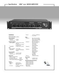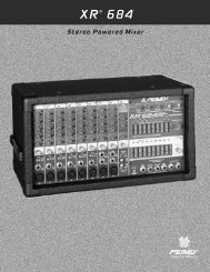
SMRTM821 Stereo Mic/Line Program Audio Mixer ... - Peavey.com
SMRTM821 Stereo Mic/Line Program Audio Mixer ... - Peavey.com
SMRTM821 Stereo Mic/Line Program Audio Mixer ... - Peavey.com

You also want an ePaper? Increase the reach of your titles
YUMPU automatically turns print PDFs into web optimized ePapers that Google loves.
SMR TM 821<br />
<strong>Stereo</strong> <strong>Mic</strong>/<strong>Line</strong><br />
<strong>Program</strong> <strong>Audio</strong> <strong>Mixer</strong><br />
User Manual<br />
Architectural Acoustics
SMR 821 User Manual<br />
Thank You! 3<br />
What's In The Box? 3<br />
Description 3<br />
Features 4<br />
Front Panel Features 5<br />
Rear Panel Features 6<br />
Installation 7<br />
Connections<br />
Channel Input 8<br />
<strong>Stereo</strong> Input 9<br />
Master Bus Link 10<br />
Remote Volume and Channel Select 11<br />
Configuration 12<br />
Applications<br />
Restaurant 14<br />
Hotel Meeting Room 15<br />
Presentation Room 16<br />
Bar 17<br />
Small House of Worship 18<br />
Plant Paging 19<br />
Courtroom 20<br />
Frequently Asked Questions (FAQ) 21<br />
Tech Support 22<br />
Warranty Registration 22<br />
Options & Modifications<br />
<strong>Mic</strong>rophone Input Transformers 23<br />
Channel 7 & 8 Select Switch Defeat Modification 25<br />
Functional Block Diagram 26<br />
E qualizer Frequency Response Chart 27<br />
Specifications 28<br />
Warranty Statement 31<br />
WARNING! To prevent electrical shock or potential fire hazards, do not expose the SMR 821 to moisture or rain. Before using this product, read the user<br />
manuals for further warnings and cautions.<br />
The following cautions should be carefully observed when installing, wiring or using this product:<br />
DO NOT use any other power supply or cable other than the one provided with this unit.<br />
DO NOT remove the top cover of the SMR 821. There are no user serviceable parts inside. Refer service to qualified personnel.<br />
DO NOT use solvents or other cleaners to clean the unit. Basic external care requires only a damp cloth. Disconnect the power supply cord before cleaning.<br />
Read all safety and installation instructions and retain all documentation for further reference.<br />
Installation of the SMR 821 should such that it’s mounting position does not interfere with proper ventilation.<br />
This product should not be installed or placed near a source of heat.<br />
Power supply cords and associated connectors should be unplugged from the power source when the unit is not used for long periods of time, or will be<br />
stored.<br />
If this product is to be mounted in an equipment rack, install rear support if required by the rack manufacturer.<br />
Care should be taken to ensure that the installation is clear of possible sources of contamination. Make sure that the product’s ventilation openings are not<br />
exposed to possible sources of liquid, gases, or other contaminant.<br />
This product should be inspected by a qualified service technician if the power supply cord or connector has been damaged, if the unit has been dropped, or if<br />
a foreign substance has gained access to the interior electronic and electrical <strong>com</strong>ponents.<br />
Page 2<br />
http://aa.peavey.<strong>com</strong> copyright 2000 All Rights Reserved
Wel<strong>com</strong>e<br />
Thank You!<br />
Thank you for purchasing the SMR 821 <strong>Mic</strong>/<strong>Line</strong> <strong>Program</strong> <strong>Mixer</strong>. This product<br />
is designed to provide years of trouble-free operation, and high quality<br />
audio performance. We sincerely hope that you enjoy your new SMR 821,<br />
and will find other products in the <strong>Peavey</strong> Architectural Acoustics product<br />
line to supplement your new mixer. We are confident that you will find the<br />
SMR 821, as well as other Architectural Acoustics products to be of the<br />
highest quality available.<br />
This manual was written to provide as much information as possible for<br />
your new <strong>Peavey</strong> Architectural Acoustics product. It is our sincere desire<br />
that you enjoy your purchase. We feel that the best way to fully enjoy any<br />
purchase is to have an in-depth understanding of the product’s features,<br />
functionality and performance characteristics. We hope that this manual,<br />
along with the manuals of our other products will provide this. If you<br />
require additional information that this manual does not provide, please let<br />
us know. We are always looking for better ways to provide information<br />
about our products, and your input is always appreciated. If you have a<br />
<strong>com</strong>ment about this manual, or would like to make a suggestion, please<br />
write to: <strong>Peavey</strong> Electronics Corp., Architectural Acoustics Division, 711 A<br />
St., Meridian MS, 39301. Thank you again for using <strong>Peavey</strong>!<br />
What’s In The Box?<br />
The SMR 821 is packaged in a single container. This container includes the<br />
following items:<br />
1- SMR 821 <strong>Mic</strong>/<strong>Line</strong> <strong>Program</strong> <strong>Audio</strong> <strong>Mixer</strong><br />
1- IEC removable power supply line cord<br />
(120VAC Domestic, 230VAC Export)<br />
2- 5-screw Euro connectors*<br />
9- 3-screw Euro connectors*<br />
1- Plastic Security Cover for EQ controls*<br />
1- User Manual/Literature Package<br />
4- Rubber feet<br />
* Asterisk indicates that these items are shipped installed on the SMR 821.<br />
If any of these items are missing, please contact your Authorized <strong>Peavey</strong><br />
Architectural Acoustics contractor/dealer.<br />
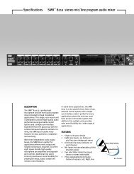
Description<br />
The SMR 821 is a professional <strong>Mic</strong>rophone and <strong>Line</strong> level audio program<br />
mixer intended for fixed installation applications. This single rack-mount<br />
package is designed to provide high quality audio performance, versatile<br />
control options and simple, easy to use controls. Engineered from the<br />
ground up with the <strong>com</strong>mercial sound systems contractor in mind, the SMR<br />
821 includes removable screw connectors for easy installation and cost effective<br />
servicing, as well as limited front panel user control.<br />
With three independent audio output buses, the SMR 821 is perfect for<br />
applications where stereo output and simple monitoring is required. Six of<br />
the eight inputs include high quality microphone pre-amplifiers and separate<br />
gain controls. Additional rear panel controls provide even more flexibility<br />
for proper gain setup, output assign and remote control features.<br />
<strong>Peavey</strong> Electronics Corp.<br />
Page 3
SMR 821 User Manual<br />
Features<br />
- Single rack space package<br />
- Eight total inputs (6 balanced <strong>Mic</strong>/<strong>Line</strong>, 2 un-balanced stereo)<br />
- LED Level/Clip status indicator on each channel<br />
- <strong>Mic</strong> inputs include selectable 48 volt phantom power<br />
- Two selectable stereo line inputs (mono or stereo switchable)<br />
- Three assignable electronically balanced outputs (Left, Right, Aux)<br />
- Master level controls for each output bus<br />
- Three 5 LED meter arrays<br />
- 4-band EQ (low, low mid, high mid, high)<br />
- Integral Ducking/Muting system<br />
- <strong>Audio</strong> and mute bus linking<br />
- Left, Right, Aux and Mute bus links for stacking multiple SMR 821’s<br />
- Rear panel Master/Slave linking mode switch<br />
- Remote stereo input select<br />
- Remote Master L/R level control port<br />
- Rear panel 20 dB pad switch on each microphone input<br />
- Front panel continuously variable preamp gain control<br />
- Rear panel bus assign switches for each microphone channel<br />
- Rear panel global 100 Hz low cut filter switch for all mic inputs<br />
- Mute bus with Channel 1 rear panel threshold control<br />
- Select switch for routing microphone mix bus post remote control<br />
- All audio I/O on removable connectors<br />
In stand alone applications, the SMR 821 is a very powerful tool. Ease<br />
of use, external control options and a simple interface make it perfect<br />
for many applications where the end user must have access to the audio<br />
system. The SMR 821’s ability to link multiple units provides even<br />
more flexibility for a wide range of applications. Among the many<br />
applications the SMR 821 was designed for include:<br />
- Presentation Rooms<br />
- Board Rooms<br />
- Courtrooms<br />
- Auditorium/Cafetorium<br />
- Lecture Hall Sound Reinforcement<br />
- Meeting Rooms<br />
- Convention Centers<br />
- Paging<br />
- Background Music<br />
- Retail Spaces<br />
- Restaurant/Bar Sound<br />
The SMR 821 is a prefect choice for many audio applications. This manual<br />
will show how some of these applications fit into the SMR 821’s<br />
feature set, and how you can maximize your system designs.<br />
To fully grasp all of the functionality and possible uses of the SMR 821,<br />
please refer to the Applications section later in this manual.<br />
Page 4<br />
http://aa.peavey.<strong>com</strong> copyright 2000 All Rights Reserved
Panel Features<br />
Front Panel Features<br />
1 2 3 4 5 6 7 8 9 10 11 12 13 14<br />
1. GAIN CONTROL This can also be referred to as a “trim” control. It varies the<br />
amount of mic preamp gain at the first gain stage.<br />
2. STATUS LED This bi-color LED illuminates green when a signal at -20dBm is present,<br />
and red when the signal level is near clipping.<br />
3. LEVEL The Level control adjusts the channel signal level sent to the mix buses.<br />
4. CHANNEL 7 & 8 LEVEL The Level control adjusts the channels’ stereo signal level<br />
sent to the mix buses.<br />
5. SELECT The Select switch is a momentary switch that selects the stereo input signal<br />
from either Channel 7 or 8. When power is applied to the SMR821, Channel 7 is<br />
selected by default.<br />
6. SELECT LED The Select LEDs indicate which stereo input channel is feeding the<br />
mix buses.<br />
7. LOW EQ The Low EQ control is a shelving type active tone control. (±15 dB at 70<br />
Hz).<br />
8. LOW MID EQ The Low Mid EQ control is a bandpass (peak/notch) type of active<br />
tone control. (±15 dB at 250 Hz).<br />
9. HI MID EQ The Hi Mid EQ control is a bandpass (peak/notch) type of active tone<br />
control. (±15 dB at 3.1 kHz).<br />
10. HI EQ The Hi EQ control is a shelving type of active tone control. (±15 dB at 10<br />
kHz).<br />
11. LEVEL METERS The three 5-segment LED Level Meters monitor the levels of the<br />
Left, Right, and Aux outputs. The 0 dB reference level corresponds to +4 dBu at its<br />
respective output connector.<br />
12. LEFT/RIGHT LEVEL The Left/Right Level control adjusts the level of the Left<br />
and Right outputs.<br />
13. AUX LEVEL The Aux Level control adjusts the output of the Auxiliary output.<br />
14. POWER LED This LED indicates that AC power is applied to the SMR 821.<br />
<strong>Peavey</strong> Electronics Corp<br />
Page 5
SMR 821 User Manual<br />
Rear Panel Features<br />
12 10 9 8 6<br />
4<br />
16 15 14 13 11 9 8 7 5<br />
3 2 1<br />
1. CHANNEL 1 MUTE THRESHOLD Adjusts the level of signal needed to trigger the muting<br />
circuitry in Channel 1.<br />
2. PAD The Pad switch attenuates the input signal by 20 dB.<br />
3. CHANNELS 1-6 INPUT Balanced microphone or line input on removable connector.<br />
4. ASSIGNMENT SWITCHES Assigns the input channel to the Left, Right, or Aux mix buses<br />
and enables the 48 volt phantom power for channels 1-6.<br />
5. LOW CUT Low Cut filter with a corner frequency of 100 Hz Enabling this switch will<br />
affect Channels 1-6 only.<br />
6. MIC MIX Allows the summed signal of Channels 1-6 to be routed before or after the remote<br />
L/R volume control.<br />
7. RIGHT OUT MUTE Controls the muting of the right mix bus. When this switch is<br />
enabled, the left and right mix buses are affected by the activity of the muting circuit. When<br />
this switch is defeated, only the left bus is affected by the muting circuit.<br />
8. MODE Selects either <strong>Stereo</strong> mode or Mono mode for Channel 7 or 8.<br />
9. CHANNELS 7 AND 8 INPUT Dual RCA connector for stereo input sources (nominally -10<br />
dBV).<br />
10. EQ Places the 4-band equalizer in or out of the Left and Right signal paths. In the OUT<br />
position the equalizer is <strong>com</strong>pletely bypassed.<br />
11. BUS LINK SWITCH For use with multiple SMR 821’s, this switch places the mixer in the<br />
master or slave mode of operation.<br />
12. LEFT OUT, RIGHT OUT, AUX OUT Main mix bus balanced outputs.<br />
13. BUS LINKS “Stacking” connector for multiple SMR 821 mixers.<br />
14. REMOTE CONNECTOR Used to control the Left/Right Master Volume Control and<br />
<strong>Stereo</strong> Input Select from a remote location.<br />
15. POWER SWITCH Applies power to the SMR821.<br />
16. A/C POWER RECEPTACLE For standard IEC power cable (included).<br />
Page 6<br />
http://aa.peavey.<strong>com</strong> copyright 2000 All Rights Reserved
Installation<br />
Installation<br />
The SMR 821 is designed to be installed in a standard EIA equipment rack.<br />
Since the depth of the unit is only 8-3/4”, you can use practically any size<br />
rack. Using only a single EIA rack space, the SMR 821 includes integral rack<br />
mounting ears and does not require any additional hardware for rack mounting.......other<br />
than the rack screws!<br />
All connections for the SMR 821 are made on the rear panel. It is re<strong>com</strong>mended<br />
that you provide an additional 4” of clearance between the rear of<br />
the chassis and the interior rear of your equipment rack for wiring harnesses.<br />
Since every connection to the SMR 821 is easy to disconnect, the unit can be<br />
removed from an equipment rack easily, without have to disturb fixed<br />
wiring harnesses.<br />
Although the SMR 821 does not generate enough heat to warrant forced air<br />
or convection cooling, it is re<strong>com</strong>mended that you provide a single rack<br />
space vent above, and below the unit when rack mounting. Using <strong>com</strong>mon<br />
sense when installing this unit will ensure that it will provide years of trouble<br />
free service. In installations where there are multiple power amplifiers, it<br />
is further re<strong>com</strong>mended that the SMR 821 be located more toward the top of<br />
the rack, while power amplifiers remain near the bottom. This is generally<br />
considered to be standard rack design in the <strong>com</strong>mercial audio industry.<br />
Following this convention will ensure adequate rack cooling and reliable<br />
operation from the SMR 821.<br />
<strong>Peavey</strong> Electronics Corp<br />
Page 7
SMR 821 User Manual<br />
Connections<br />
Connecting the SMR 821 is not much different than any other analog audio<br />
product. There are inputs and outputs, but there are also additional connections<br />
that you need to be aware of . These include the external control ports<br />
and the Bus Link connectors. All cables for these connections should be<br />
shielded. Refer to the following illustrations for each type of connection.<br />
<strong>Audio</strong> Input<br />
The inputs to the SMR 821 are balanced. This means that there are three wires for each connection, a positive, negative and<br />
shield. These should be connected to each pin accordingly.<br />
Balanced <strong>Mic</strong>rophone or <strong>Line</strong> Level Input<br />
Shield<br />
<strong>Audio</strong> Negative<br />
<strong>Audio</strong> Positive<br />
Figure 1. Balanced <strong>Audio</strong> Input Connections<br />
Insert jumper wire between the negative<br />
and shield pins for un-balanced circuits.<br />
Un-Balanced <strong>Mic</strong>rophone or <strong>Line</strong> Level Input<br />
Shield<br />
<strong>Audio</strong> “Hot” or Positive<br />
Figure 2. Un-Balanced <strong>Audio</strong> Input Connections<br />
Page 8<br />
http://aa.peavey.<strong>com</strong> copyright 2000 All Rights Reserved
Connections<br />
<strong>Stereo</strong> Inputs<br />
Channels 7 and 8 provide two individual inputs for each channel. These are intended for stereo use, as each input (Left, Right)<br />
has a fixed assignment to the Left and Right output buses. Additionally, a sum of both inputs is fed simultaneously to the Aux<br />
output bus. Although you cannot change the distribution of these inputs, you can determine if they are stereo or mono. The<br />
Mode Switch, when enabled, will sum both connectors, feeding both to the Left and Right outputs simultaneously. These connectors<br />
accept nominal levels of -10dBV.<br />
The Mode switch selects either <strong>Stereo</strong> mode or Mono mode individually<br />
for Channel 7 or 8. In the <strong>Stereo</strong> mode, the Left input signal<br />
feeds the Left mix bus and the Right input signal feeds the Right<br />
mix bus via the front panel Level Control. In the Mono mode, the<br />
summed Left and Right input signals feed both Left and Right mix<br />
buses. This allows for only one input to be used to feed the stereo<br />
mix buses. Additionally, it allows for Left and Right outputs of the<br />
source to be summed without a Y-cable. In either mode, a summed<br />
mono signal feeds the Aux mix bus.<br />
Unbalanced RCA connections<br />
Left Shield<br />
Left “Hot” <strong>Audio</strong><br />
Right Shield<br />
Right “Hot” <strong>Audio</strong><br />
The cabling for these connectors should be of<br />
the standard, consumer un-balanced shielded<br />
type. If you are using a 2-conductor shielded<br />
cable, make sure to connect the negative side of<br />
the signal to the shield. NOTE: Unbalanced<br />
signal sources should be located within approximately<br />
6’ of the SMR-821.<br />
Figure 3. RCA Input Connections<br />
<strong>Peavey</strong> Electronics Corp<br />
Page 9
SMR 821 User Manual<br />
Master Bus Output & Link Connections<br />
These connectors allow you to expand your SMR 821. The Bus Links connector has 5 pins for <strong>com</strong>bining multiple SMR 821’s.<br />
Using a 4-conductor, shielded cable, you can easily connect between 2 or more units wiring pin-to-pin across multiple SMR 821<br />
mixers. NOTE: Use only shielded cable! Refer to the illustrations below.<br />
<strong>Audio</strong> Bus Outputs, Typical For Each Bus<br />
Master <strong>Mixer</strong><br />
<strong>Audio</strong> Positive<br />
<strong>Audio</strong> Negative<br />
Shield<br />
In a linked system, the Master mixer’s<br />
outputs would be the primary system<br />
outputs.<br />
The EQ switch places the 4-band equalizer in or out of the<br />
Left and Right signal paths. In the OUT position the equalizer<br />
is <strong>com</strong>pletely bypassed.<br />
The Bus Link switch is used to place the mixer in the master<br />
or slave mode of operation. A stand-alone unit should<br />
always be in the master mode.<br />
Master Bus & Mute Link Connections<br />
Left <strong>Audio</strong> Link (L)<br />
Right <strong>Audio</strong> Link (R)<br />
Link Shield (SHD)<br />
Aux <strong>Audio</strong> Link (A)<br />
Mute Bus Link (M)<br />
Slave <strong>Mixer</strong> 1<br />
To increase the number of inputs available, multiple mixers may<br />
be linked together. Linking mixers is a very simple process. Wire<br />
the Bus Links connections between each mixer. Select the mixer<br />
to be used as the master and place its Bus Link Switch in the<br />
MASTER position. All other mixers in the system should have<br />
their link switches in the SLAVE position. The EQ and master<br />
level controls of the unit chosen as MASTER should be used to<br />
control the system. NOTE: Slave mixer outputs are still active,<br />
and will output any channels assigned to them.<br />
Slave <strong>Mixer</strong> 2<br />
Figure 4. Master Output & Bus Link Connections<br />
Page 10<br />
http://aa.peavey.<strong>com</strong> copyright 2000 All Rights Reserved
Connections<br />
External Control Connections<br />
The SMR 821 provides a powerful external control option. This feature allows you to configure remote controls for the Master<br />
Left/Right volume and the Channel 7/8 select function. The Remote connector provides a simple way to make these connections.<br />
NOTE: Use only shielded cable! Refer to the illustrations below.<br />
This example is used to control the Left/Right Master Volume<br />
Control from a remote location with a simple connection on the<br />
back of the unit. A 10k pot will provide approximately 0 to 30dB of<br />
attenuation. A 100k pot will provide about 0 to 60dB of attenuation.<br />
If desired, a control voltage can be inserted to “<strong>com</strong>mand”<br />
attenuation instead of a pot. This voltage is inserted into the “C”<br />
input and is positive referenced to SHD. NOTE: THE CONTROL<br />
VOLTAGE SHOULD NEVER EXCEED 11 VOLTS DC.<br />
Remote Volume Control Connections<br />
Volume Control to Potentiometer CW Leg (V)<br />
Control to Potentiometer Wiper Leg (C)<br />
Shield Potentiometer CCW Leg (SHD)<br />
Remote<br />
Volume<br />
Figure 5. Remote Volume Control Connections<br />
This example shows the connection for remote selection of the<br />
Channels 7 or 8 input select feature. The selection is done by connecting<br />
a momentary switch between SEL and SHD. Each time<br />
the switch is actuated, the channel selection is toggled and alternated<br />
between Channel 7 and 8. This remote operation functions<br />
in conjunction with the front panel Select Control. A bi-color<br />
LED or 2 individual LEDs may be connected as shown in the<br />
diagram for remote indication of the selected stereo line input.<br />
NOTE: The IND circuit can supply a maximum of 6ma for the<br />
LEDs’. Take care that you do not exceed this current limitation.<br />
Remote Channel 7/8 Select Connections<br />
Shield (SHD)<br />
Channel 7/8 Select (SEL)<br />
Indicator LED Output (IND)<br />
Ch 7-8<br />
Select<br />
Switch<br />
Ch 7-8<br />
Select LEDs<br />
Ch 8<br />
Ch 7<br />
Figure 6. Remote Channel 7/8 Select Connections<br />
<strong>Peavey</strong> Electronics Corp<br />
Page 11
SMR 821 User Manual<br />
Configuration<br />
Since the SMR 821 is an analog product, there is not a lot of configuration to worry about. No software, no data cables,<br />
no networks and no headaches. However, there are a few things to remember while you begin to use your new SMR<br />
821 mixer.<br />
The SMR 821 is shipped from the factory ready to go. You should be able to follow the steps below, and get audio<br />
through the unit.<br />
The first step is to calibrate your gain settings for the inputs. Each microphone input<br />
has a Gain Control and a Level Control. These controls work together, while the<br />
Status LED and the master Level Meters provide a visual indication of the control’s<br />
behavior. To properly adjust the SMR 821 for optimal performance, follow these simple<br />
steps for each input channel:<br />
1. Adjust the Channel, Master L/R and Aux Level Controls so they are at the midpoint.<br />
There is a “center detent” on the control which indicates this position.<br />
Figure 7. Input Channel Controls<br />
2. Adjust the channel Gain Control to its minimum position, or fully counter-clockwise<br />
for the channel you are working on.<br />
3. Apply an audio signal to the input by either playing a line level audio source<br />
or by speaking into a microphone at a nominal level. While monitoring the<br />
master Level Meters, slowly adjust the Gain Control clockwise while audio is<br />
present. Keep turning the control until the Level Meters are indicating nominal<br />
level around the -6 to 0dB area on the meters. In addition, the channel<br />
Status LED should be green and not red. The bi-color Status LED illuminates<br />
green when a signal is present at -20 dBu. It illuminates red when the signal<br />
level is near clipping. The Level Control adjusts the signal level sent to the mix<br />
buses. This control should be operated near the mid-point of its travel to assure<br />
an optimized signal-to-noise ratio and maximum headroom, once the Gain Figure 8. Master Meters and Controls<br />
Control is set correctly. If you find that the input signal is too hot, and you<br />
cannot properly adjust the gain control without causing a clipping condition, you will need to use the Pad Switch,<br />
located on the rear panel. This switch will give you an additional 20dB of pad beyond what the front panel Gain<br />
Control provides. Follow this procedure for each input to ensure proper gain structure.<br />
For channels 7 and 8, there is no gain control. To properly adust the gain on<br />
these channels, you will need to control the output level of the audio source.<br />
With the Channel Level and the Master Level controls at the detent position,<br />
a -10dBV signal will present a +4dBu output at the Bus Output connectors.<br />
It is important to adjust the gain DOWN enough so the preamp will not clip at<br />
louder levels. Carefully consider the type of audio source, and adjust the gain<br />
settings accordingly. Material with wide dynamic range will generally require<br />
a lower Gain Control setting, while material that is fairly constant, can usually<br />
tolerate a higher setting.<br />
Figure 9. Master Meters and Controls<br />
After these adjustments are made, make sure you monitor the front panel LED’s<br />
and meters during normal use. Take note of the action of the Status LED’s. Under normal operation, you should see<br />
lots of green, but it is not unusual to see occasional flashes of red. Constant red, however, indicates that a gain setting<br />
is improperly adjusted, and should be re-set using the above procedure.<br />
Page 12<br />
http://aa.peavey.<strong>com</strong> copyright 2000 All Rights Reserved
Configuration<br />
The next step is to configure the SMR 821’s many rear panel switches for your application. Although the unit is<br />
shipped from the factory with default switch values, you should make sure that these settings are correct for YOUR<br />
application. Let’s take a look at each one, and describe their functionality.<br />
First, there are the Channels 1-6 Bus Assign Switches. These switches provide<br />
the ability to assign each input to the Left, Right or Aux output buses. In addition,<br />
you can turn on or off the phantom power on each channel. There is a single<br />
8-position DIP switch for each TWO input channels. Take care that you are<br />
adjusting the correct switch for the correct channel. It is re<strong>com</strong>mended that you<br />
use a small screwdriver or other instrument to set the switches. Do not force<br />
them. Also, keep in mind that the ON position is on top. Figure 10 shows the DIP<br />
switches with all functions in the ON position. NOTE: The factory setting is all<br />
bus assign switches ON, and phantom OFF.<br />
Figure 11. <strong>Mic</strong> Mix, Rt Out Mute<br />
and Low Cut Switches<br />
About the middle of the rear panel, you will find a<br />
group of three switches. They include the <strong>Mic</strong> Mix<br />
switch, the Rt Out Mute switch and the Low Cut switch. The <strong>Mic</strong> Mix switch allows<br />
the summed signal of Channels 1-6 to be routed before or after the remote L/R volume control.<br />
In the “Pre Remote” position, the signals from Channels 1-6 are affected by the remote<br />
volume control along with the stereo input from the either Channel 7 or 8. In the Post<br />
Remote position, only the stereo input from either Channel 7 or 8 is affected by the remote<br />
volume control. The factory default setting is “Pre-Remote”.<br />
The Rt Out Mute switch controls the muting of the right mix bus. The factory setting of<br />
this switch is “Enable”. When enabled, the left and right mix buses are affected by the<br />
activity of the Channel 1 muting circuit. When this switch is defeated, only the left bus is<br />
affected by the muting circuit. Use the Channel 1 Mute Threshold control to set the trigger point to activate the muting.<br />
The Low Cut Switch enables a filter with a corner frequency of 100 Hz and is helpful to filter out rumble, wind noise,<br />
breath thumps, and other low-frequency signals that rob amplifier power and muddy the mix. Enabling this switch<br />
will affect Channels 1-6 only. The factory default setting for the Low Cut switch is “Defeat” or “Flat”.<br />
The Mode switch selects either <strong>Stereo</strong> mode or Mono mode for Channel 7 or 8. In<br />
the <strong>Stereo</strong> mode, the Left input signal feeds the Left mix bus and the Right input<br />
signal feeds the Right mix bus via the front panel Level control. In the Mono mode,<br />
the summed Left and Right input signals feed both Left and Right mix buses. This<br />
allows for a mono source to be used to feed the stereo mix buses. Additionally, it<br />
allows for Left and Right outputs of the source to be summed without a Y-cable. In<br />
either mode, a summed mono signal feeds the Aux mix bus. The factory default is<br />
“<strong>Stereo</strong>”.<br />
Figure 10. Input Channel Bus Assign<br />
Switches and Input Connectors<br />
The EQ switch places the 4-band stereo equalizer in or out of the Left and Right signal<br />
paths. In the OUT position the equalizer is<br />
<strong>com</strong>pletely bypassed. The factory default is IN.<br />
Figure 12. Channel 7 & 9 Mode Switches<br />
The Bus Link switch is used to place the mixer in the master or slave mode of operation.<br />
A stand-alone unit should always be in the master mode, and the factory<br />
default is MASTER. See the “Connections” section of this manual for details on Bus<br />
Linking and using multiple SMR 821’s.<br />
Figure 13. Channel 7 & 9 Mode Switches<br />
That’s about it for configuration. As you can see, the SMR 821 provides many powerful<br />
features for better, more cost effective systems. The multiple <strong>com</strong>binations of<br />
routing, control and input assignment facilitate a wide range of applications.<br />
<strong>Peavey</strong> Electronics Corp<br />
Page 13
SMR 821 User Manual<br />
Restaurant<br />
You’ve seen them...you know, the trendy restaurants at major off-ramps of every interstate in the country. Good<br />
atmosphere, OK food, high prices, young staff and a sports-oriented bar. This is a great market for sound system work,<br />
since all of these places have multiple zones of audio, video distribution and paging. The SMR 821 is perfect for these<br />
applications and provides a very simple interface for the end user. Take a look....<br />
Manager’s Page<br />
Bar Page<br />
Hostess Page<br />
All Buses<br />
Aux Bus<br />
Right Bus<br />
Satellite Receiver<br />
Lobby Zone<br />
Main Seating Area<br />
Left<br />
Right<br />
Bar Seating<br />
Patio Seating<br />
Aux<br />
System Features:<br />
- Two independent music feeds. The L/R outputs are further<br />
split into two separate zones.<br />
- Hostess paging “ducks” music source using the Channel 1<br />
threshold feature. This is normally used for the “your table<br />
is ready!” page.<br />
- Remote control of volume at the hostess podium.<br />
- Remote control of music source at the manager’s office.<br />
This source select switch could be placed at multiple locations<br />
by paralleling.<br />
- Each microphone is assigned independently. The Hostess<br />
mic feeds all zones, the manager’s mic feeds only the Main<br />
Seating area and the bar mic feeds only the bar and the<br />
patio zones.<br />
Manager’s<br />
Office<br />
Hostess<br />
Podium<br />
Music Source<br />
Select Panel<br />
Master<br />
Volume<br />
Control Panel<br />
Page 14<br />
http://aa.peavey.<strong>com</strong> copyright 2000 All Rights Reserved
Applications<br />
Hotel Meeting Rooms<br />
The SMR 821 is a very powerful product for use in meeting rooms. The use of the Bus Link feature provides the ability<br />
to <strong>com</strong>bine, separate or control multiple units. In this example, we shall see how multiple SMR 821’s can be used<br />
effectively for meeting room applications.<br />
Emergency Page Source<br />
In-Room <strong>Mic</strong>s<br />
Main Music Source (BGM)<br />
In Room Control<br />
Music On/Off<br />
Master Volume<br />
(Master)<br />
Room A<br />
Power Amplifier<br />
Room Combine<br />
A& B<br />
In Room Control<br />
Music On/Off<br />
Master Volume<br />
Room B<br />
Power Amplifier<br />
Room Combine<br />
B & C<br />
In Room Control<br />
Music On/Off<br />
Master Volume<br />
Room C<br />
Power Amplifier<br />
System Features:<br />
- Shown as a 3-Room System, this configuration could allow for larger <strong>com</strong>binations.<br />
- Each room has it’s own local inputs and outputs, independent of the others. In addition, there is a wall mounted control panel<br />
in each room with a music ON/OFF switch and Master Volume control. These are wired to the remote control ports on the<br />
SMR 821’s Remote Connector.<br />
- A Room Combine panel allows linking of adjacent rooms, or all three rooms. These are simple switches wired between the<br />
SMR 821’s Bus Link ports. In this example, we are linking the main audio and the mute bus.<br />
- The “house” BGM audio is fed to all three rooms. The music ON/OFF control is actually the Channel 7/8 Remote Select, but<br />
since there is no music on Channel 7, the switch acts as an OFF control.<br />
- The emergency page audio is wired to each mixer’s Channel 1 input. When a page is active, all music will mute, and the page<br />
will be allowed to go through. Since this page source is paralleled across all of the Channel 1 inputs, it has priority over all<br />
other inputs, and is independent of the Room Combine mode.<br />
This system could be configured many different ways. For example, you could use the Channel 7 input in each room for a local<br />
music source and determine if the remote control “mutes” or “selects” the music. The Room Combine panels could be located at<br />
the equipment rack to prevent un-authorized tampering, or in the hallways for banquet personnel to adjust.<br />
<strong>Peavey</strong> Electronics Corp<br />
Page 15
SMR 821 User Manual<br />
Presentation Room<br />
What exactly is a “Presentation Room” anyway? Well, it could be many things. It could be a small board room in a<br />
corporate environment, or a large theatre-style classroom in a major university. Or, it could be a folding table in your<br />
shop, used to present new ideas to your installation crew. Basically, any place that ideas or information can be presented<br />
to a group of people could be classified as a “Presentation Room”. In this example, we will assume that our<br />
Presentation Room has a sound system, video display system and a means to control these systems centrally or by<br />
remote control.<br />
<strong>Audio</strong> From<br />
Video<br />
L C R<br />
Control<br />
System<br />
Left<br />
Right<br />
Aux<br />
<strong>Stereo</strong><br />
Loudspeakers<br />
Center<br />
Loudspeaker<br />
System Features:<br />
- <strong>Mic</strong>rophone Inputs for speech reinforcement on channels 1, 2 and 3 assigned to the Aux Bus only.<br />
- Inputs for audio from video switcher. Left, Center and Right audio channels connected to channels 4, 5 and 6, assigned to Left,<br />
Center and Aux output buses respectively. This will provide for 3-channel playback with dialog on the center (AUX) bus and<br />
the music bed on the stereo (LEFT, RIGHT) bus.<br />
- <strong>Stereo</strong> tape playback on Channel 7 distributed to Left, Right and Center channels.<br />
- <strong>Stereo</strong> CD playback on Channel 8 distributed to Left, Right and Center channels.<br />
- Interface with control system with dry contact, resistance and voltage control for Tape/CD select and overall volume control.<br />
- Outputs for 3 channels of audio. Left/Right and Aux. The Aux bus provides the audio for the center channel.<br />
The Control System in this example is typical of many popular software based systems. The control circuit that is connected to<br />
the SMR-821 would be a dry contact or variable resistance type of connection. Typically, the source controls, in this case the<br />
CD player and the tape deck, would be infrared control connections.<br />
Page 16<br />
http://aa.peavey.<strong>com</strong> copyright 2000 All Rights Reserved
Applications<br />
Bar<br />
Yeah, you know. A bar...or “club”. This example assumes a small bar with live music, but not a full blown stage with<br />
lights and huge flying loudspeaker arrays, etc. Basically, this is the type of bar where you go to get some food, have<br />
some adult beverages and kick back. The music is low-key, usually a small acoustic guitar-vocal group or a solo<br />
singer-songwriter. You need to be able to reinforce the live inputs, provide control for the background music, allow<br />
for simple paging and give the bar manager a “turn it down” knob. You can do this and more with the SMR 821.<br />
Live<br />
Music<br />
<strong>Mic</strong>s<br />
Page<br />
<strong>Mic</strong><br />
Bar Manager’s<br />
Master Volume<br />
Control<br />
Hostess<br />
BGM Mute<br />
Control<br />
<strong>Stereo</strong> Live Music<br />
Loudspeakers<br />
Left<br />
Right<br />
Patio, Rear Bar &<br />
Restroom<br />
Loudspeakers<br />
Aux<br />
System Features:<br />
- Separate loudspeaker systems for the live music area and the rest of the facility.<br />
- Background music source is defeatable by remote switch at hostess podium or cash register. Additionally, this control can be<br />
located at the stage area as well, so the performer can mute the BGM when the live performance begins.<br />
- Live mics are routed throughout the bar, but at separate levels for areas not in the direct vicinity of the performer are under<br />
separate volume control.<br />
- Master volume control is under the control of the Bar Manager.<br />
<strong>Peavey</strong> Electronics Corp<br />
Page 17
SMR 821 User Manual<br />
Small House of Worship<br />
For small churches, synagogues or similar houses of worship, the SMR 821 is a perfect choice. A very simple interface,<br />
high quality audio performance and multiple outputs make it ideal. Similar products in this price range may be well<br />
suited for paging or background music, but generally do not have the audio quality required for speech presentation or<br />
live musical performance.<br />
Pastor<br />
Altar<br />
Choir<br />
Choir<br />
Vocal<br />
Piano<br />
Usher’s Control Panel<br />
Master Volume<br />
Music Mute<br />
Main Cluster<br />
Nursery, Foyer<br />
Hallways, Restrooms<br />
Left<br />
Right<br />
Choir Monitor<br />
Aux<br />
System Features:<br />
- Independent audio feeds for the Sanctuary and the Nursery, Foyer, Hallways and Restrooms.<br />
- Aux feed with separate level control for the choir.<br />
- Remote Control of master volume and music mute via wall mounted panel in the foyer.<br />
- Six microphone inputs are plenty for a small facility.<br />
- High quality audio performance.<br />
- Simple, easy to use front panel and remote controls eliminate the need for a console.<br />
- Low cost installation.<br />
Page 18<br />
http://aa.peavey.<strong>com</strong> copyright 2000 All Rights Reserved
Applications<br />
Plant Paging<br />
For large scale paging applications, the SMR 821 is a cost effective option to digital systems. By using multiple units<br />
and “busing” <strong>com</strong>mon inputs, you can create multiple zone systems. In this example, each area of this facility has it’s<br />
own local paging and music audio. A <strong>com</strong>mon “All Call” mic is fed to each zone’s Channel 1 input.<br />
Office<br />
All Call<br />
Shop Floor<br />
Supervisor<br />
Office<br />
Manager<br />
Local Music<br />
ZONE 1 - Assembly Plant<br />
NOTE: When busing audio<br />
inputs across long distances,<br />
it is re<strong>com</strong>mended<br />
that the optional<br />
<strong>Mic</strong>rophone Input<br />
Transformer accessory be<br />
installed. See the Options<br />
& Modifications section<br />
later in this manual for<br />
installation instructions.<br />
Loading<br />
Dock<br />
Picking<br />
Clerk<br />
Local Music<br />
Shop Floor<br />
Administrative Offices<br />
ZONE 2- Warehouse<br />
Loading Docks<br />
Inventory Locations<br />
To Other Locations<br />
System Features<br />
- Independent paging and music audio for each zone.<br />
- All call paging distributed to all zones mutes or “ducks” the local music source and local paging mics.<br />
- Independent outputs for each area allow for different volume settings.<br />
- Remote control option provides the ability to create a master volume and music mute control.<br />
<strong>Peavey</strong> Electronics Corp<br />
Page 19
SMR 821 User Manual<br />
Courtroom<br />
In this example, we need more than 6 microphones for this courtroom project. Using the SMR 821’s Bus Link feature,<br />
we can easily create a 12x2 mixer. The Master mixer feeds the power amplifiers and the logging recorder. Using the<br />
Aux output for the logging recorder provides a separate volume control, and channel assignment. In some cases, you<br />
may not want every microphone to log to tape. Keeping the recorder feed separate provides this functionality.<br />
Judge Judy<br />
Court Reporter<br />
Clerk<br />
Witness<br />
Jury Foreman<br />
Portable<br />
Master<br />
Volume<br />
Slave<br />
Defense Attorney 1<br />
Defense Attorney 2<br />
Defense Aux<br />
Prosecution 1<br />
Prosecution 2<br />
Prosecution Aux<br />
Bus Link<br />
Master<br />
Main Courtroom<br />
Spectator Area<br />
Logging Recorder<br />
System Features<br />
- 12 microphone inputs.<br />
- Separate feeds for main speakers, spectator speakers and tape recorder.<br />
- Bus Link feature provides seamless <strong>com</strong>bining of two mixers.<br />
Page 20<br />
http://aa.peavey.<strong>com</strong> copyright 2000 All Rights Reserved
FAQ<br />
Frequently Asked Questions<br />
I just hooked up my new SMR 821, and I can’t get audio from any of the outputs.<br />
A <strong>com</strong>mon cause for this is the Bus Assign switches not being assigned to any of the outputs. Make sure that the input you are<br />
using is assigned to the output bus that you have your amplifier connected to.<br />
When I adjust the equalizer controls on the front panel, nothing happens.<br />
Check the rear panel EQ switch. If this switch is in the OUT position, the front panel EQ is defeated.<br />
I want to feed 2 mono music sources independently to the Left and Right outputs. How can I do this?<br />
You can actually connect 4 mono sources, two for each output (Left, Right). By configuring the Channel 7 and 8 MODE switches<br />
to MONO, you can create dual 2x1 switchers. Each of the Left inputs will feed the Left output, depending on the position of<br />
the front panel Channel 7/8 select switch. The same applies to the Right inputs.<br />
I am using the Left and Right outputs in mono for music and paging in a 2-zone configuration. However, I want one<br />
zone to be independent of the Channel 1 muting feature. How can I do this, and still keep the other zone’s muting<br />
feature active?<br />
By default, the SMR 821’s muting feature is active on both the Left and Right outputs. However, you can disable this feature for<br />
the Right channel by enabling the rear panel RT OUT MUTE switch. Also, the AUX output is not affected by the action of the<br />
Channel 1 mute feature.<br />
When I connect my high quality condenser microphone, I cannot get any indication that the mic is working. I have<br />
confirmed that the gain structure and output assign functions are properly set. What is going on?<br />
Most condenser microphones require an external phantom power source to operate. Activate the phantom power for the<br />
microphone input channel where your condenser microphone is connected. This phantom power switch is located in the BUS<br />
ASSIGN switch bank for each channel. To activate phantom power, turn down all Level Controls and then place this switch in<br />
the ON position.<br />
I have a paging microphone connected to Channel 1 and a music source on Channel 7. I want the music to mute<br />
whenever a page is made, but it doesn’t seem to work. What am I doing wrong?<br />
Most likely, you do not have the Channel 1 MUTE THRESHOLD control adjusted properly. This control has to be adjusted so<br />
that when a nominal level is present at the microphone, the music will mute. Care should be taken in this adjustment however,<br />
because a setting that is too low will require an excessive level at the microphone to activate the mute function. A setting that<br />
is too high could inadvertently mute ambient sounds near the microphone location.<br />
I would like to build a remote control panel for volume control. Can I connect a remote potentiometer for each<br />
channel?<br />
No. Only the Master Volume control is capable of external control.<br />
I would like to link multiple mixers. If I do this, can I still use the main outputs from each mixer?<br />
Yes. In a linked configuration, the MASTER mixer’s outputs include audio from ALL mixers in the link. However, the outputs<br />
of the Slave mixers are still active, and can be used to feed “local” circuits.<br />
I have a CD player connected to Channel 2, instead of the stereo inputs. The sound quality is very poor. Why?<br />
Check your wiring. Channel 2 is a single balanced input, and most CD players have dual un-balanced outputs. In this configuration,<br />
you will need either sum the two CD outputs to a single output, or use just one of the outputs. In addition, you will<br />
need to add a jumper between the negative and shield terminals. Also, make sure you use the PAD switch to prevent overloading.<br />
(See the “Connections” section of this manual for details).<br />
The sound system where my SMR 821 is installed needs to be on 24 hours a day. Is this OK?<br />
Yes. The SMR 821 is designed to operated continuously.<br />
<strong>Peavey</strong> Electronics Corp<br />
Page 21
SMR 821 User Manual<br />
Tech Support<br />
<strong>Peavey</strong> has an extensive Technical Services Group that provides tech support,<br />
repair and implementation services. If you require assistance with your<br />
new SMR821, you can get help from several sources. There are many technical<br />
documents, white papers and application notes on our website as well as<br />
brochures, data sheets and our newsletter, “<strong>Audio</strong> Interactive”, published<br />
monthly. Also on our website are message board forums that include questions<br />
and answers on all audio topics. This forum is a great way to learn<br />
more about audio, <strong>Peavey</strong> products and system design from other audio professionals<br />
around the world. You can also get help by sending us an e-mail<br />
or posting a request on the message board. Finally, if you still cannot get the<br />
information you need, don’t hesitate to call us. We have extensive phone<br />
support services and will be happy to assist you. The contact information<br />
for the Architectural Acoustics Division is shown below:<br />
<strong>Peavey</strong> Electronics Corp.<br />
Architectural Acoustics Division<br />
711 “A” St.<br />
Meridian MS 39301<br />
USA<br />
Phone: 601-483-5376<br />
Fax: 601-486-1678<br />
Website: http://aa.peavey.<strong>com</strong><br />
Email: levin@peavey.<strong>com</strong> (Technical Services Manager)<br />
Warranty Registration<br />
Please take a few minutes and fill out the warranty registration card for<br />
your SMR 821. Although your warranty is valid without the registration, the<br />
information you provide with the form is crucial to our support group. It<br />
enables us to provide better service and customer support, and to keep you<br />
informed of new product updates, and software revisions. Refer to the warranty<br />
statement on the back page of this manual for details about what your<br />
warranty includes and what the limitations are.<br />
Page 22<br />
http://aa.peavey.<strong>com</strong> copyright 2000 All Rights Reserved
Options & Modifications<br />
Optional Features<br />
The SMR 821 offers optional features for specific job requirements. These<br />
options include Transformers for the microphone inputs and the ability to<br />
defeat the functionality of the Channel 7/8 select switch.<br />
!<br />
These options and modifications require access to the inside of the SMR<br />
821. It is highly re<strong>com</strong>mended that the installation of the optional<br />
microphone transformers and the modification of the Channel 7/8 select<br />
switch be performed by qualified service personnel. There are dangerous<br />
voltages present inside the unit, as well as static sensitive <strong>com</strong>ponents.<br />
Damage to the SMR 821’s internal circuitry caused by un-qualified<br />
persons is not covered under warranty, and in fact, could void the<br />
warranty altogether.<br />
Installing the Optional <strong>Mic</strong>rophone Input Transformers<br />
Optional transformers for use with the microphone input circuits are available from <strong>Peavey</strong> Electronics Corp. (part #<br />
70500852). The optional transformers may be added one at a time, all at once, or in any <strong>com</strong>bination. To ensure that the transformers<br />
are properly installed, please refer to the instructions and illustrations in this section. If you have ANY questions, or<br />
are not sure about it, do not hesitate to call our Tech Support Group.<br />
Refer to Figure 14. “Cutaway of circuit board showing jumper locations for installation of optional microphone transformers”<br />
while performing the following steps:<br />
1. Unplug the SMR821 from the AC voltage source.<br />
2. Remove the 6 screws securing the top panel of the SMR821. Remove the top and set aside.<br />
3. Remove the 5 screws securing the rear panel to the chassis.<br />
4. Remove the 5 screws securing the front panel to the chassis.<br />
5. Carefully turn the SMR821 upside down.<br />
6. Remove the 11 screws securing the circuit board assembly to the chassis.<br />
7. Carefully turn the entire SMR821 right side up. One end of the circuit board assembly (with the front and rear panels still<br />
attached) can be lifted out of the chassis with power supply wires still intact to access the bottom side of the circuit board.<br />
8. Locate the six round transformer outlines.<br />
9. Before installing the transformers, you will need to cut some jumpers and resistors. These <strong>com</strong>ponents are labeled with reference<br />
designators on the board.<br />
10. For each transformer installed, three jumpers and one resistor will need to be cut. The following table shows which <strong>com</strong>ponents<br />
need to be cut for their corresponding transformer.<br />
Transformer T101 T1201 T301 T401 T501 T601<br />
Components J102, J103, J202, J203, J302, J303, J402, J403, J502, J503, J602, J603,<br />
to be cut J105, R116 J205, R216 J305, R316 J405, R416 J505, R516 J605, R616<br />
11. The transformers can only be inserted into the board one way. Place a transformer into the circuit board and solder in place.<br />
Repeat for each transformer being installed.<br />
Re-installing the Circuit Board and Re-assembling the Unit<br />
1. Place the circuit board assembly (with the front and rear panels still attached) into the chassis.<br />
2. Carefully turn the SMR821 upside down and replace the 11 screws securing the circuit board assembly to the chassis.<br />
3. Carefully turn the unit right side up.<br />
4. Replace the 5 screws securing the front panel to the chassis.<br />
5. Replace the 5 screws securing the rear panel to the chassis.<br />
6. Place the top panel on the chassis and replace the 6 screws securing it to the chassis.<br />
<strong>Peavey</strong> Electronics Corp<br />
Page 23
SMR 821 User Manual<br />
Cut Jumper Here<br />
Cut Jumper Here<br />
Cut Resistor Here<br />
Cut Jumper Here<br />
NOTE: Cuts are<br />
typical for each<br />
channel where<br />
the transformers<br />
will be installed.<br />
Do not cut these<br />
jumpers UNLESS<br />
a transformer is<br />
installed for that<br />
channel!<br />
BE CAREFUL!<br />
Figure 14. Cutaway of circuit board showing jumper locations for installation of optional microphone transformers<br />
Page 24<br />
http://aa.peavey.<strong>com</strong> copyright 2000 All Rights Reserved
Options & Modifications<br />
Channel 7/8 Modification<br />
This modification changes the functionality of the Channel 7/8 front panel select switch and the busing of the audio inputs.<br />
When this modification is <strong>com</strong>plete, the front panel switch will act as a “MUTE” switch for all signals connected to the<br />
Channel 7 and 8 RCA input connectors. In addition, BOTH stereo channels (7 and 8) will SIMULTANEOUSLY feed the Left,<br />
Right and Aux output buses. The “Select” action of the switch is defeated.<br />
Refer to Figure 15. “ Cutaway of circuit board showing jumper location for Channel 7/8 Modification” while performing the following steps:<br />
1. Unplug the SMR821 from the AC voltage source.<br />
2. Remove the 6 screws securing the top panel of the SMR821. Remove the top and set aside.<br />
3. Locate and cut the jumper J905. It is located near the power supply.<br />
4. Place the top panel on the chassis and replace the 6 screws securing it to the chassis.<br />
Cut Jumper Here<br />
Figure 15. Cutaway of circuit board showing jumper location for modification of the Channel 7/8 Modification<br />
<strong>Peavey</strong> Electronics Corp<br />
Page 25
SMR 821 User Manual<br />
Figure 16. SMR 821 Functional Block Diagram<br />
Page 26<br />
http://aa.peavey.<strong>com</strong> copyright 2000 All Rights Reserved
Specifications<br />
d<br />
B<br />
r<br />
+20<br />
+18<br />
+16<br />
+14<br />
+12<br />
+10<br />
+8<br />
+6<br />
+4<br />
+2<br />
-0<br />
-2<br />
-4<br />
-6<br />
-8<br />
-10<br />
-12<br />
-14<br />
-16<br />
-18<br />
-20<br />
SMR 821 STEREO MIC/LINE PROGRAM MIXER<br />
20 50 100 200 500 1k 2k 5k 10k 20k<br />
Hz<br />
4-Band Equalizer<br />
0 dBr = +4 dBu<br />
Figure 17. SMR 821 Equalizer Response Plot<br />
<strong>Peavey</strong> Electronics Corp<br />
Page 27
SMR 821 User Manual<br />
Specifications<br />
MECHANICAL<br />
Dimensions (H x W x D)<br />
Weight<br />
Mounting<br />
Connections<br />
1.75" x 19" x 8.75" (45 mm x 483 mm x 222 mm)<br />
7.4 lbs.<br />
Single EIA Space Rack Mount<br />
Removable “Euro” Connectors for single channel audio inputs, outputs, bus link and<br />
external control. RCA single-ended female for Channels 7 and 8 stereo inputs. IEC<br />
receptacle for AC power.<br />
PERFORMANCE<br />
Test Conditions<br />
120Vac 60Hz maintained throughout testing.<br />
Input Sensitivity<br />
Input<br />
<strong>Mic</strong>rophone<br />
without pad<br />
<strong>Mic</strong>rophone<br />
with pad<br />
<strong>Mic</strong>rophone<br />
without pad<br />
(optional<br />
transformer)<br />
<strong>Mic</strong>rophone<br />
with pad<br />
(optional<br />
transformer)<br />
Input<br />
Impedance<br />
(Ohms)<br />
2k<br />
2k<br />
2k<br />
2k<br />
Input gainpot<br />
setting<br />
Max gain<br />
+60 dB<br />
Min gain<br />
+10 dB<br />
Max gain<br />
+40 dB<br />
Min gain<br />
–10 dB<br />
Max gain<br />
+60 dB<br />
Min gain<br />
+20 dB<br />
Max gain<br />
+40 dB<br />
Min gain<br />
0 dB<br />
Input Level, dBu<br />
Min.* Nom.** Max.<br />
–76dBu –56dBu –39dBu<br />
–25dBu –4dBu +13dBu<br />
–56dBu –36dBu –19dBu<br />
–5dBu +16dBu +33dBu<br />
–74dBu –54dBu –37dBu<br />
–34dBu –14dBu +3dBu<br />
–54dBu –34dBu –17dBu<br />
–14dBu +6dBu +23dBu<br />
Balanced/<br />
Unbalanced<br />
Balanced<br />
Balanced<br />
Balanced<br />
Balanced<br />
Connector<br />
+<br />
–<br />
Ground<br />
+<br />
–<br />
Ground<br />
+<br />
–<br />
Ground<br />
+<br />
–<br />
Ground<br />
<strong>Stereo</strong> <strong>Line</strong> 10k N/A –20dBV –10dBV +7dBV Unbalanced RCA jacks<br />
0 dBu = 0.775 Vrms<br />
0 dBV = 1.00 Vrms<br />
* Min. input level (sensitivity) is the smallest signal that will produce a nominal<br />
output with controls set at maximum gain.<br />
** Nominal settings are defined as all controls set at center detent for nominal<br />
output. <strong>Mic</strong>rophone gain control is as specified.<br />
Page 28<br />
http://aa.peavey.<strong>com</strong> copyright 2000 All Rights Reserved
Specifications<br />
Output Specifications<br />
Output<br />
Min Load<br />
Output Level<br />
Impedance Nom Max<br />
Left/Right 600 ohms +4dBu<br />
Aux 600 ohms +4dBu<br />
0 dBu = 0.775 Vrms<br />
0 dBm = 1 mW<br />
+21dBu<br />
+19dBm<br />
+21dBu<br />
+19dBm<br />
Balanced/<br />
Unbalanced<br />
Balanced<br />
Balanced<br />
Connector<br />
+<br />
–<br />
Ground<br />
+<br />
–<br />
Ground<br />
Noise<br />
Output Signal/Noise (typical) Test Conditions<br />
Left/Right<br />
100 dB<br />
All Level controls down<br />
Aux<br />
84 dB<br />
80 dB<br />
95 dB<br />
92 dB<br />
81 dB<br />
Master Level control nominal<br />
Channel Level controls down<br />
All controls nominal<br />
All channels assigned<br />
<strong>Mic</strong> gain minimum<br />
All Level controls down<br />
Master Level control nominal<br />
Channel Level controls down<br />
All controls nominal<br />
All channels assigned<br />
<strong>Mic</strong> gain minimum<br />
Gain<br />
<strong>Mic</strong> Input Range without pad:<br />
<strong>Mic</strong> Input to Output without pad:<br />
<strong>Mic</strong> Input Range with pad:<br />
<strong>Mic</strong> Input to Output with pad:<br />
<strong>Mic</strong> Input Range without pad<br />
(optional transformer):<br />
<strong>Mic</strong> Input to Output without<br />
pad (optional transformer):<br />
<strong>Mic</strong> Input Range with pad<br />
(optional transformer):<br />
<strong>Mic</strong> Input to Output with pad<br />
(optional transformer):<br />
10dB to 60dB<br />
80dB max<br />
-10dB to 40dB<br />
60dB max<br />
20 dB to 60 dB<br />
80dB max<br />
0 dB to 40 dB<br />
60dB max<br />
<strong>Peavey</strong> Electronics Corp<br />
Page 29
SMR 821 User Manual<br />
Frequency Response<br />
20Hz - 20kHz +0dB/-1dB<br />
Total Harmonic Distortion<br />
Plus Noise<br />
70dB typical 20Hz - 20kHz<br />
Crosstalk<br />
Adjacent Channels (1kHz)<br />
>70dB typical<br />
Crosstalk<br />
Output to Output (1kHz)<br />
>60dB typical<br />
Phantom Power<br />
+48 Volts at mic + and - inputs<br />
Remote Volume Control<br />
30dB attenuation (10k ohm potentiometer ) Typical<br />
60dB attenuation (100k ohm potentiometer) Typical<br />
Channel Mute<br />
>60dB attenuation<br />
Signal/Clip Indicators<br />
Input Channel Status<br />
Green: -20dBu<br />
Red: 2dB below clipping<br />
Output Level Meters<br />
-24: -20dBu<br />
-6: -2dBu<br />
0: +4dBu<br />
+6: +10dBu<br />
Clip: 2dB below clipping<br />
Power Requirements<br />
Domestic: 120Vac, 60Hz 15 Watts nominal<br />
Export: 230Vac, 50/60Hz 15 Watts nominal<br />
Page 30<br />
http://aa.peavey.<strong>com</strong> copyright 2000 All Rights Reserved
Warranty Statement<br />
Architectural Acoustics ®<br />
PEAVEY ELECTRONICS CORPORATION LIMITED WARRANTY<br />
Effective Date: July 1, 1998<br />
What This Warranty Covers<br />
Your <strong>Peavey</strong> Warranty covers defects in material and workmanship in <strong>Peavey</strong> products purchased and serviced in the U.S.A. and Canada.<br />
What This Warranty Does Not Cover<br />
The Warranty does not cover: (1) damage caused by accident, misuse, abuse, improper installation or operation, rental, product modification or<br />
neglect; (2) damage occurring during shipment; (3) damage caused by repair or service performed by persons not authorized by <strong>Peavey</strong>; (4)<br />
products on which the serial number has been altered, defaced or removed; (5) products not purchased from an Authorized <strong>Peavey</strong> Dealer.<br />
Who This Warranty Protects<br />
This Warranty protects only the original retail purchaser of the product.<br />
How Long This Warranty Lasts<br />
The Warranty begins on the date of purchase by the original retail purchaser. The duration of the Warranty is as follows:<br />
Product Category<br />
MediaMatrix ® DPU, (Excluding Frames), Cinema Processors,<br />
Power Amplifiers, Pre-Amplifiers, <strong>Mixer</strong>s,<br />
Electronic Crossovers and Equalizers<br />
Loudspeakers<br />
<strong>Mic</strong>rophones<br />
Speaker Components (including speakers, baskets, drivers,<br />
diaphragm replacement kits and passive crossovers)<br />
and all Accessories<br />
Duration<br />
2 years *(+ 3 years)<br />
3 years *(+ 2 years)<br />
2 years<br />
90 days<br />
[*denotes additional warranty period applicable if optional Warranty Registration Card is <strong>com</strong>pleted and returned to <strong>Peavey</strong> by original retail purchaser<br />
within 90 days of purchase.]<br />
What <strong>Peavey</strong> Will Do<br />
We will repair or replace (at <strong>Peavey</strong>'s discretion) products covered by warranty at no charge for labor or materials. If the product or <strong>com</strong>ponent<br />
must be shipped to <strong>Peavey</strong> for warranty service, the consumer must pay initial shipping charges. If the repairs are covered by warranty, <strong>Peavey</strong><br />
will pay the return shipping charges.<br />
How To Get Warranty Service<br />
(1) Take the defective item and your sales receipt or other proof of date of purchase to your Authorized <strong>Peavey</strong> Dealer or Authorized <strong>Peavey</strong><br />
Service Center.<br />
OR<br />
(2) Ship the defective item, prepaid, to <strong>Peavey</strong> Electronics Corporation, International Service Center, 412 Highway 11 & 80 East, Meridian, MS<br />
39301 or <strong>Peavey</strong> Canada Ltd., 95 Shields Court, Markham, Ontario, Canada L3R 9T5. Include a detailed description of the problem, together<br />
with a copy of your sales receipt or other proof of date of purchase as evidence of warranty coverage. Also provide a <strong>com</strong>plete return address.<br />
OR<br />
(3) All MediaMatrix ® Frames needing repair, should be shipped prepaid to <strong>Peavey</strong> Electronics Corporation, International Service Center, 412<br />
Highway 11 & 80 East, Meridian, MS 39301<br />
Limitation of Implied Warranties<br />
ANY IMPLIED WARRANTIES, INCLUDING WARRANTIES OF MERCHANTABILITY AND FITNESS FOR A PARTICULAR PURPOSE, ARE LIM-<br />
ITED IN DURATION TO THE LENGTH OF THIS WARRANTY.<br />
Some states do not allow limitations on how long an implied warranty lasts, so the above limitation may not apply to you.<br />
Exclusions of Damages<br />
PEAVEY'S LIABILITY FOR ANY DEFECTIVE PRODUCT IS LIMITED TO THE REPAIR OR REPLACEMENT OF THE PRODUCT, AT PEAVEY'S<br />
OPTION. IF WE ELECT TO REPLACE THE PRODUCT, THE REPLACEMENT MAY BE A RECONDITIONED UNIT. PEAVEY SHALL NOT BE<br />
LIABLE FOR DAMAGES BASED ON INCONVENIENCE, LOSS OF USE, LOST PROFITS, LOST SAVINGS, DAMAGE TO ANY OTHER<br />
EQUIPMENT OR OTHER ITEMS AT THE SITE OF USE, OR ANY OTHER DAMAGES WHETHER INCIDENTAL, CONSEQUENTIAL OR OTH-<br />
ERWISE, EVEN IF PEAVEY HAS BEEN ADVISED OF THE POSSIBILITY OF SUCH DAMAGES.<br />
Some states do not allow the exclusion or limitation of incidental or consequential damages, so the above limitation or exclusion may<br />
not apply to you.<br />
This Warranty gives you specific legal rights, and you may also have other rights which vary from state to state.<br />
If you have any questions about this warranty or service received or if you need assistance in locating an Authorized Service Center, please contact<br />
the <strong>Peavey</strong> International Service Center at (601) 483-5365 / <strong>Peavey</strong> Canada Ltd. at (905) 475-2578.<br />
Features and specifications subject to change without notice.<br />
<strong>Peavey</strong> Electronics Corp<br />
Page 31
Features and Specifications subject to change without notice.<br />
A product of <strong>Peavey</strong> Electronics Corporation<br />
711 A Street / Meridian, MS 39301 / USA / (601) 483-5376 / FAX (601) 486-1678<br />
http://aa.peavey.<strong>com</strong><br />
Copyright 2000 All Rights Reserved 80304714 Printed in USA 4/2000