IVO Smart
IVO Smart
IVO Smart

Create successful ePaper yourself
Turn your PDF publications into a flip-book with our unique Google optimized e-Paper software.
GEBRUIKERSHANDLEIDING / USERS MANUAL / BETRIEBSANLEITING<br />
MODE D’EMPLOI / MANUAL DE UTILIZACION / INSTRUZIONI PER L’USO<br />
MASTERVOLT<br />
Snijdersbergweg 93, 1105 AN Amsterdam<br />
The Netherlands<br />
Tel.: +31-20-342 21 00<br />
Fax.: +31-20-697 10 06<br />
<strong>IVO</strong> <strong>Smart</strong><br />
12/35-3, 12/50-3, 24/15-3<br />
Acculader / Battery charger / Akkuladegerät /<br />
Chargeur de batteries / Caricabatterie / Cargador de baterías<br />
www.mastervolt.com V1.0-070105
Productbeschrijving<br />
De <strong>IVO</strong> <strong>Smart</strong> 12/35-3, 12/50-3 en 24/15-3 zijn<br />
temperatuurgecompenseerde acculaders voor het<br />
laden en op spanning houden van loodaccu’s en<br />
het voeden van de op de accu aangesloten<br />
gebruikers, in vast opgestelde installaties. Alle<br />
modellen zijn voorzien van twee hoofduitgangen<br />
(2 en 3) en een extra ‘Slave’-uitgang (5) die de<br />
mogelijkheid biedt voor de onderhoudslading van<br />
een kleine extra accuset met dezelfde nominale<br />
spanning, zoals een startaccu. De maximale<br />
laadstroom van deze ‘Slave’-uitgang bedraagt 3<br />
Ampère, welke ten laste gaat van de laadstroom<br />
van de hoofduitgang. De spanningsverliezen over<br />
de aansluitkabels worden automatisch<br />
gecompenseerd.<br />
Acculader<br />
De lader is uitgerust met drie LED’s (11, 12 en<br />
13, zie figuur 4), die de status van de drietraps<br />
laadkarakteristiek weergeven (zie figuur 1):<br />
• LED 11 licht op: hoofdlading (bulk).<br />
• LED 11 en 12 lichten beide op: naladen<br />
(absorption).<br />
• LED 11, 12 en 13 lichten op: de accu is vol<br />
(float).<br />
Figuur 1: Laadkarakteristiek.<br />
Indien de indicatie uit is terwijl de stekker<br />
van het AC netsnoer in het stopcontact zit,<br />
dient u contact op te nemen met de<br />
leverancier.<br />
Bediening<br />
De lader werkt automatisch. Bediening is onder<br />
normale omstandigheden dan ook niet nodig. Een<br />
eventuele foutmelding, zoals onder- en<br />
overspanning, oververhitting of kortsluiting is<br />
alleen via een bedieningspaneel weer te geven<br />
d.m.v. een “Failure” indicator.<br />
Uitgebreide functies<br />
• Analoge aansluiting (7): Het optionele basic<br />
Mastervolt paneel (C4-RB, 70404100) wordt<br />
aangesloten door middel van een 6-aderige<br />
communicatiekabel tussen het paneel en de<br />
analoge RJ12 aansluiting.<br />
NEDERLANDS<br />
• Digitale aansluiting (6): De andere optionele<br />
Mastervolt panelen worden aangesloten door<br />
middel van een 6-aderige communicatiekabel<br />
tussen het paneel en de digitale RJ12<br />
aansluiting. Het communicatie protocol is<br />
gebaseerd op quasi RS 232. Het is ook<br />
mogelijk om via deze aansluiting softwarematig<br />
diverse instellingen aan te passen aan uw<br />
specifieke wensen (besturingssoftware en<br />
interface optioneel leverbaar).<br />
Zie de Mastervolt internetsite “www.mastervolt.com”<br />
voor toepassingen.<br />
5 2 3 4<br />
6 7 8 9 10<br />
Figuur 2: Aansluitingen.<br />
Instellingen<br />
Onder de minaansluiting bevinden zich 3 jumpers<br />
(8, 9 en 10) voor specifieke toepassingen van de<br />
lader. Om onderstaande functies te activeren<br />
dient u de jumper met een klein tangetje of pincet<br />
te verwijderen.<br />
Verwijder de netstekker uit het<br />
stopcontact alvorens één van de<br />
jumpers te verwijderen of te plaatsen.<br />
Foutieve instellingen kunnen tot schade<br />
leiden aan accu’s welke niet onder de<br />
garantie vallen. Laat veranderingen<br />
alleen door gekwalificeerde elektriciens uitvoeren.<br />
• De lader werkt enkel als druppellader (force<br />
float) indien u jumper (8) verwijdert.<br />
• De lader is geschikt voor het laden van gel-<br />
/AGM-/spiraalaccu’s (high float) door jumper<br />
(9) te verwijderen.<br />
• Indien een scheidingsdiode wordt toegepast<br />
om meerdere accu’s tegelijk te laden, kunt u<br />
de spanningval over de diode compenseren<br />
door jumper (10) te verwijderen. Hiermee<br />
wordt de uitgangsspanning van alle uitgangen<br />
met 0,6V verhoogd.
Aanwijzingen voor installatie<br />
• Gebruik deugdelijke kabelschoenen om de<br />
bedrading op de uitgang van de lader aan te<br />
sluiten en draai alle verbindingen stevig aan.<br />
• Zie de specificatie voor de aanbevolen<br />
draaddoorsnede.<br />
• Neem in de plusleidingen een zekering op in<br />
de bedrading en plaats deze zo dicht mogelijk<br />
bij de accu. Zie specificaties voor aanbevolen<br />
zekeringen.<br />
• In verband met mogelijke condensvorming en<br />
optimale warmteafvoer, dient u de acculader<br />
in een goed geventileerde ruimte, zo dicht<br />
mogelijk bij de accu’s te installeren. Wij<br />
adviseren om de lader verticaal, met de<br />
aansluitkabels naar beneden te monteren.<br />
• Monteer het product nooit direct boven een<br />
accu i.v.m. mogelijke corrosieve accudampen.<br />
Ter vermindering van EMC- interferentie<br />
adviseren wij de negatieve pool van de<br />
voedingsaccu te verbinden met de massa.<br />
Installatie<br />
Voor een juiste installatie zie de tekening<br />
“INSTALLATION” voor de verwijzingen tussen<br />
haakjes.<br />
1. Overtuig uzelf ervan dat de netstekker van de<br />
acculader gedurende de<br />
installatiewerkzaamheden niet is aangesloten.<br />
Zorg er tevens voor dat er geen gebruikers<br />
zijn aangesloten op de accugroepen ter<br />
voorkoming van onveilige situaties.<br />
2. Sluit de accusets met de juiste polariteit aan<br />
op de acculader. Sluit de negatieve uitgang<br />
(4) van de lader aan op de min (–) pool van<br />
de accu. Sluit de positieve uitgang (2 of 3)<br />
van de lader aan op de plus (+) pool van de<br />
accusets. De pluspool van een extra accuset<br />
(startaccu) kunt u aansluiten op de ‘Slave’<br />
uitgang (5). Draai alle verbindingen stevig<br />
aan.<br />
3. Installeer de temperatuursensor zodanig dat<br />
deze een juist beeld geeft van de<br />
temperatuur van de accu’s. Sluit de<br />
temperatuursensor aan op een van de vrije<br />
RJ12 aansluitingen (6 of 7).<br />
4. Steek de stekker van het AC netsnoer in het<br />
stopcontact. De acculader zal nu de<br />
laadcyclus starten.<br />
NEDERLANDS<br />
Veiligheidsvoorschriften en maatregelen.<br />
• Installeer het product volgens de aangegeven<br />
instructies.<br />
• Gebruik het product nooit op een locatie met<br />
gas of stofontploffingsgevaar.<br />
• Aansluitingen en beveiligingen moeten in<br />
overeenstemming met de plaatselijk geldende<br />
voorschriften worden uitgevoerd.<br />
• In het product komen hoge spanningen voor.<br />
Gebruik het product alleen met gesloten<br />
behuizing.<br />
Bij verwisseling van de plus- en min<br />
aansluitingen op de accu zal de lader<br />
defect raken. Dit defect valt niet onder<br />
de garantie. Gebruik geen zwaardere zekeringen<br />
dan gespecificeerd.<br />
Garantiebepalingen<br />
Mastervolt garandeert dat het product is<br />
gebouwd volgens de wettelijk van toepassing<br />
zijnde normen en bepalingen. Gedurende de<br />
productie en voor aflevering zijn alle producten<br />
uitvoerig getest en gecontroleerd. Wanneer niet<br />
volgens de in deze handleiding gegeven<br />
voorschriften, aanwijzingen en bepalingen wordt<br />
gehandeld, kunnen beschadigingen ontstaan<br />
en/of het product zal niet aan de specificaties<br />
voldoen. Een en ander kan inhouden dat de<br />
garantie komt te vervallen.<br />
De garantietermijn is 2 jaar<br />
Aansprakelijkheid<br />
Mastervolt kan niet aansprakelijk worden gesteld<br />
voor:<br />
• Schade ontstaan door het gebruik van dit<br />
product.<br />
• Eventuele fouten in bijbehorende handleiding<br />
en de gevolgen daarvan.<br />
• Ander gebruik geldend als niet conform de<br />
bestemming van het product.
Product description<br />
The <strong>IVO</strong> <strong>Smart</strong> 12/35-3, 12/50-3 and 24/15-3 are<br />
full automatic battery chargers for temperature<br />
compensated charging and maintaining the<br />
charged condition of lead batteries and supplying<br />
users connected to a battery in permanent<br />
installations. All models are provided with two<br />
separate main DC-outlets (2 en 3) and an<br />
additional ‘Slave’-terminal (5) that offers the<br />
possibility to give a maintenance charge to a<br />
small second battery set (e.g. starter battery)<br />
with the same nominal voltage. The maximum<br />
charge current of the Slave Charger is 3 Amps,<br />
which is reduced from the main output of the<br />
charger. The voltage drop over the DC-wires is<br />
automatically compensated.<br />
Battery charger<br />
The charger is equipped with three green LED<br />
indicators (11, 12 and 13, see figure 4) that<br />
indicate the status of the three-step charge<br />
characteristic (see figure 1).<br />
• LED (11) illuminates: bulk charge.<br />
• LED’s (11 and 12) illuminate: absorption<br />
charge.<br />
• LED’s (11, 12 and 13) illuminate: batteries<br />
are maintained in fully charged condition (float<br />
charge)<br />
Figure 1: Charge characteristic<br />
If the indicator is off while the plug of the<br />
AC-cable is connected to the mains,<br />
contact your supplier.<br />
Operation<br />
The charger operates automatically. Under normal<br />
circumstances, there is no need for operation.<br />
Possible failures like under and over voltage,<br />
overheating or short circuit are reported via a<br />
remote control only by means of a failure<br />
indicator.<br />
Extended functions<br />
• Analogue modular jack (7): The optional Basic<br />
Mastervolt panel (C4-RB, 70404100) shall be<br />
connected by using a communication cable<br />
between the control panel and the analogue<br />
remote RJ12 input.<br />
ENGLISH<br />
• Digital modular jack (6): The other optional<br />
Mastervolt remote panels are connected by<br />
using a communication cable between the<br />
panel and the digital remote RJ12 input. The<br />
communication protocol is based on a quasi<br />
RS 232 interface. It is also possible to use this<br />
port to make adjustments in terms of software<br />
to your specific demands (control software and<br />
interface not included).<br />
Check the Mastervolt internet site<br />
“www.mastervolt.com” for applications.<br />
5 2 3 4<br />
6<br />
7<br />
Figure 2: Connections.<br />
8 9 10<br />
Settings<br />
For specific applications of the charger, there are<br />
three jumpers (8, 9, and 10) below the negative<br />
output. If necessary, the jumpers can be removed<br />
with small tongs or tweezers.<br />
Disconnect the charger from AC-mains<br />
before removing or placing the jumpers.<br />
Wrong adjustment can cause damage to<br />
your batteries which is not covered by<br />
the warranty. Only allow changes to be<br />
carried out by qualified electricians.<br />
• The charger only functions as a maintenance<br />
charger (forced float), if jumper (8) is<br />
removed.<br />
• The charger is suitable for charging<br />
gel/AGM/spiral batteries (high float), if jumper<br />
(9) is removed.<br />
• In case a battery isolator (diode) is used to<br />
charge several batteries, the charging voltage<br />
of all outputs is increased (0,6V) to<br />
compensate the voltage drop if jumper (10) is<br />
removed
Directions for installation<br />
• Use reliable cable lugs to fix the wires to the<br />
DC-output and fasten all connections tightly.<br />
• Refer to specifications for the diameter of the<br />
cables to be used to connect the batteries to<br />
the charger.<br />
• Integrate a fuse in the positive wiring and<br />
place it nearby the battery. See specifications<br />
for the recommended fuse.<br />
• Due to possible moisture accumulation and<br />
optimal heat discharge, the battery charger<br />
must be installed in a well-ventilated room as<br />
close as possible to the batteries. We advise<br />
to mount the unit in a vertical position with<br />
the connecting cables downward.<br />
• Do not install the product straight above the<br />
batteries because of possible corrosive<br />
sulphur fumes.<br />
To minimize any EMC-interference we<br />
advise to connect the negative pole of the<br />
supplying battery to the ground.<br />
Installation<br />
For correct installation see the references<br />
between brackets () in the “INSTALLATION”<br />
drawing.<br />
1. Be sure the battery charger is disconnected<br />
from any power source and that no load is<br />
connected to the batteries during installation.<br />
2. Connect the charger’s negative output (4) to<br />
the minus pole (–) of the battery. Connect<br />
the charger’s positive output (2 or 3) to the<br />
plus pole (+) of the battery. The plus pole of<br />
an optional extra battery set (e.g. a starter<br />
battery) should be connected to the slave<br />
output (5).<br />
3. The temperature sensor can be plugged into<br />
one of both RJ12 plugs (6 or 7). Locate the<br />
temperature sensor at a spot that is<br />
representative for the battery’s temperature.<br />
4. Plug the AC mains cable into the wall socket.<br />
The battery charger will now commence the<br />
charging cycle.<br />
ENGLISH<br />
Safety regulations and measures<br />
• Install the product according to the stated<br />
instructions.<br />
• Never use the product at a location where<br />
there is danger of gas or dust explosions.<br />
• Connections and safety features must be<br />
executed according to the locally applicable<br />
regulations.<br />
• The product may only be taken into operation<br />
while the cover is closed as lethal voltages<br />
may exist.<br />
If the plus and minus connections on the<br />
battery are exchanged, the charger will<br />
be damaged. This kind of damage is not<br />
covered by the warranty. Do not use fuses<br />
larger than those indicated in the specifications.<br />
Guarantee terms<br />
Mastervolt guarantees that this product was built<br />
according to the legally applicable standards and<br />
stipulations. During production and before<br />
delivery all products were exhaustively tested<br />
and controlled. If you fail to act in accordance<br />
with the regulations, instructions and stipulations<br />
in this user’s manual, damage can occur and/or<br />
the product will not fulfil the specifications. This<br />
may mean that the guarantee will become null<br />
and void.<br />
The guarantee period is 2 years.<br />
Liability<br />
Mastervolt cannot be held liable for:<br />
• Damage resulting from the use of the<br />
converter.<br />
• Possible errors in the included manual and the<br />
consequences of these.<br />
• Use that is inconsistent with the purpose of<br />
the product
Produktbeschreibung<br />
Die Modelle <strong>IVO</strong> <strong>Smart</strong> 12/35-3, 12/50-3 und<br />
24/15-3 sind vollautomatische Akkuladegeräte<br />
zum Aufladen und Aufrechterhalten der<br />
Spannung von Bleiakkus und zum Speisen von<br />
an die Akkus angeschlossenen Verbrauchern in<br />
festen Installationen. Alle Modelle verfügen über<br />
zwei separate Ausgänge und einen extra<br />
Ausgang für eine Unterhaltungsladung eines<br />
kleinen zusätzlichen Akkus (z.B. eine<br />
Starterbatterie). Dieser Ausgang hat die gleiche<br />
Ausgangsspannung wie der Hauptausgang und<br />
verfügt über einen maximalen Strom von 3<br />
Ampere, der von dem Ladestrom der<br />
Hauptbatterie reduziert wird. Die Ladegeräte<br />
kompensieren automatisch die<br />
Spannungsverluste in den Anschlusskabeln.<br />
Batterielader<br />
Auf dem Ladegerät befinden sich drei grüne LED-<br />
Anzeigeleuchten (11, 12 und 13, Abbildung 4),<br />
die den Status der 3-Stufen-Ladecharakteristik<br />
anzeigen (Abbildung 1).<br />
•<br />
•<br />
•<br />
LED (11) leuchtet auf: Hauptladung (“Bulk“)<br />
LED’s (11 und 12) leuchten auf:<br />
Ausgleichsladung (“Absorption“)<br />
LED’s (11, 12 und 13) leuchten auf:<br />
Erhaltungsladung (“Float“)<br />
Figuren 1: Ladecharakteristik<br />
Wenn die LED-Anzeige nicht aufleuchtet,<br />
obwohl der Stecker des AC-Netzkabels in<br />
der Steckdose steckt, müssen Sie sich an<br />
den Lieferanten wenden.<br />
Betrieb<br />
Der Akkuladegeräte funktioniert automatisch.<br />
Unter normalen Umständen ist eine<br />
Inbetriebnahme nicht erforderlich. Mögliche<br />
Fehler, wie Über- und Unterspannung,<br />
Überhitzung, oder ein Kurzschluss werden an der<br />
optionalen Fernbedienungseinheit von der<br />
Failure- (Fehler-) LED gemeldet.<br />
Fortschrittliche Funktionen<br />
• Analoger Modulstecker (7): Das wahlweise<br />
Mastervolt Basis-Panel (C4-RB, 70404100)<br />
wird mit einem Kommunikationskabel<br />
zwischen dem Kontroll-Panel und dem<br />
DEUTSCH<br />
analogen Eingang RJ12 der Fernbedienung<br />
angeschlossen.<br />
• Digitaler Modulstecker (6): Die anderen<br />
Wahlweisen Mastervolt Fernbedienungspanele<br />
werden mit einem Kommunikationskabel<br />
zwischen dem Panel und dem digitalen<br />
Eingang RJ12 der Fernbedienung<br />
angeschlossen. Es ist auch möglich, diesen<br />
Anschluss zu nutzen, um softwaremäßige<br />
Anpassungen entsprechend Ihrer spezifischen<br />
Anforderungen vorzunehmen (die<br />
Anwendersoftware und das Interface sind<br />
nicht inbegriffen).<br />
Die Anwendersoftware kann auf der Website<br />
“www.mastervolt.com” heruntergeladen werden.<br />
Figuren 2: Anschlüsse<br />
Einstellungen<br />
Unter dem Minusausgang befinden sich 3 Jumper<br />
(8, 9 und 10) für spezifische Anwendungen des<br />
Ladegeräts. Auf Wunsch können die Jumper mit<br />
einer kleinen Zange oder Pinzette entfernt<br />
werden.<br />
•<br />
•<br />
•<br />
5 2 3 4<br />
6<br />
7<br />
8 9 10<br />
Ziehen Sie den Netzstecker des<br />
Ladegeräts aus der Steckdose, bevor Sie<br />
Jumper entfernen oder einsetzen.<br />
Eine falsche Einstellung kann zu<br />
Schäden an Ihren Batterien führen,<br />
welche in der Gewährleistung nicht<br />
enthalten sind. Lassen Sie Änderungen nur durch<br />
qualifizierte Elektriker durchführen.<br />
Beim Entfernen von Jumper (8) arbeitet das<br />
Ladegerät nur als Erhaltungslader (force<br />
float).<br />
Beim Entfernen von Jumper (9) eignet sich<br />
das Ladegerät zum Laden von Gel/AGM/spiral<br />
Akkus (high float).<br />
Beim Entfernen von Jumper (10) wird die<br />
Ausgangsspannung zur Kompensation einer<br />
Batterietrenndiode erhöht (0,6V) für den Fall,<br />
dass mehrere Batterien gleichzeitig geladen<br />
werden müssen.
Anzeigen für Installation<br />
Für die richtige Anschlussweise siehe Zeichnung<br />
„Installation“.<br />
• Benützen Sie zuverlässige Kabelendhülsen,<br />
um die Kabel am AC-Eingang und DC–<br />
•<br />
Ausgang zu befestigen.<br />
Nehmen Sie für die Kabeldurchmesser zum<br />
Anschluss der Akkus an das Ladegerät Bezug<br />
auf die Spezifikationen.<br />
• Schließen Sie eine Sicherung in der Nähe der<br />
Batterie an das Pluskabel an. Siehe<br />
•<br />
Spezifikationen für die empfohlene Sicherung.<br />
Installieren Sie den Akkulader in einem gut<br />
belüfteten Raum möglichst nahe bei den<br />
Akkus. Im Hinblick auf eine eventuelle<br />
Ansammlung von Feuchtigkeit und eine<br />
optimale Wärmeableitung empfehlen wir, die<br />
Einheiten mit den Anschlusskabeln nach<br />
unten zu montieren.<br />
• Montieren Sie den Akkulader niemals direkt<br />
oberhalb der Batterien, wegen möglicher<br />
korrosiver Batteriedämpfe.<br />
Zur Verringerung sämtlicher<br />
elektromagnetischer Störungen wird<br />
empfohlen, den Minuspol der<br />
Versorgerbatterie zu erden.<br />
Installation<br />
1. Überzeugen Sie sich davon, dass der<br />
Akkulader während der Installation nicht an<br />
eine Stromquelle angeschlossen ist und dass<br />
keine Last angeschlossen ist.<br />
2. Schließen Sie das Minuskabel zwischen den<br />
Minuspol (–) des Akkus und den<br />
Minusausgang (4) des Ladegerätes an, und<br />
das Pluskabel zwischen den Pluspol (+) des<br />
Akkus und den Plusausgang (2 oder 3) des<br />
Ladegerätes. Den Pluspol eines zusätzlichen<br />
Akkus (z.B. eine Starterbatterie) können Sie<br />
an den zweiten Ausgang (5) des Ladegerätes<br />
anschließen. Verwenden Sie<br />
widerstandsfähige Anschlüsse und befestigen<br />
Sie diese sicher.<br />
3. Schließen Sie den Akku-Temperatursensor an<br />
und platzieren Sie ihn an einer Stelle, die für<br />
die Batterietemperatur repräsentativ ist. Der<br />
Temperatursensor kann in einen der beiden<br />
Stecker RJ12 (6 oder 7) eingesteckt werden.<br />
4. Stecken Sie den Stecker des AC-Netzkabels in<br />
die Steckdose. Der Akkulader beginnt jetzt<br />
den Ladezyklus.<br />
DEUTSCH<br />
Sicherheitsvorschriften und -maßnahmen<br />
• Installieren Sie den Stromrichter gemäß den<br />
genannten Anweisungen.<br />
• Benutzen Sie den Gleichrichter nie in einer<br />
Umgebung, in der die Gefahr einer Gas- oder<br />
Staubexplosion besteht.<br />
• Anschlüsse und Sicherheitsvorkehrungen<br />
müssen den lokalen Vorschriften<br />
entsprechend ausgeführt werden.<br />
• Der Gleichrichter darf nur mit geschlossenem<br />
Gehäuse in Betrieb genommen werden, da<br />
Lebensgefährdende Spannungen anliegen<br />
können.<br />
Wenn die Plus- und Minus-Anschlüsse<br />
der Batterie vertauscht werden, kann<br />
das Akkuladegerät kaputt gehen.<br />
Verwenden Sie keine größeren Sicherungen als<br />
die in den Spezifikationen angegebenen.<br />
Garantiebestimmungen<br />
Mastervolt garantiert, dass das Produkt unter<br />
Einhaltung der gesetzlichen Normen und<br />
Bestimmungen gebaut ist. Bei der<br />
Herstellung und vor der Lieferung werden alle<br />
Geräte ausführlich getestet und kontrolliert.<br />
Wenn die in dieser Gebrauchsanleitung<br />
beschriebenen Vorschriften, Anweisungen und<br />
Bestimmungen nicht beachtet werden, können<br />
Schäden entstehen und/oder das Gerät kann<br />
seine Spezifikationen nicht mehr einhalten. In<br />
diesem Fall kann keine Garantie mehr geleistet<br />
werden.<br />
Die Garantiezeit beträgt 2 Jahre<br />
Haftung<br />
Mastervolt haftet nicht für:<br />
• durch die Benutzung des Produkts<br />
entstandene Schäden.<br />
• mögliche Fehler in der mitgelieferten Anleitung<br />
und die daraus entstehenden Folgen.<br />
• einen anderen Gebrauch, d.h. einen Gebrauch,<br />
der nicht mit der Bestimmung des Produkts<br />
übereinstimmt.
Description de l’appareil<br />
Les <strong>IVO</strong> <strong>Smart</strong> 12/35-3, 12/50-3 et 24/15-3 sont<br />
des chargeurs automatiques de batteries<br />
permettant de charger avec compensation de<br />
température et maintenir les sous tension les<br />
batteries au plomb et d’alimenter des utilisateurs<br />
raccordés à la batterie, dans des installations<br />
fixes. Tous les modèles sont fournis avec deux<br />
sorties CC séparées (2 et 3) et une sortie esclave<br />
(5) qui permet de maintenir la charge d'un<br />
deuxième petit parc de batteries (par exemple<br />
une batterie de démarrage) avec la même<br />
tension nominale. Le courant de charge de 3<br />
Ampère est retenu du courant de charge de la<br />
sortie première. La chute de tension sur les<br />
câbles CC est compensée automatiquement.<br />
Chargeur de batterie<br />
Le chargeur est doté des indicateurs (LED) vert<br />
(11,12 et 13, voyez figures 1) pour signifier<br />
l’état de la courbe de charge à 3 étapes (voyez<br />
figures 1).<br />
• LED (11) s’allume: « bulk », la batterie est<br />
chargée rapidement, jusqu’à 80% environ.<br />
• LED (11 et 12) s’allument: « absorption », la<br />
batterie est chargée de 80 à 100%.<br />
• LED (11,12 et 13) s’allument: « float », la<br />
charge de la batterie est maintenue à 100%.<br />
Figure 1: Caractéristique de charge<br />
Si le voyant est éteint alors que la prise<br />
du câble CA est branchée sur le secteur,<br />
contacter votre revendeur.<br />
Fonctionnement<br />
Le chargeur fonctionne automatiquement. Dans<br />
des conditions normales d’utilisation, aucune<br />
intervention n’est nécessaire. Le voyant pannes<br />
de la commande à distance permet le<br />
signalement de défaillances éventuelles, telles<br />
que sous-tension ou surtension, surchauffe ou<br />
court-circuit.<br />
Fonctions étendues<br />
• Prise modulaire analogique (7) : le panneau<br />
de contrôle de base Mastervolt en option (C4-<br />
RB, réf. 70404100) doit être connecté en<br />
utilisant un câble de communication entre le<br />
FRANÇAIS<br />
panneau de contrôle et la prise analogique<br />
RJ12.<br />
• Prise modulaire digitale (6) : les autres<br />
panneaux de contrôle Mastervolt en option<br />
sont connectés par un câble de<br />
communication entre le panneau et la prise<br />
digitale RJ12. Ce port peut également être<br />
utilisé pour effectuer des réglages au niveau<br />
logiciel en fonction de vos besoins spécifiques<br />
(logiciel de contrôle et interface non fournis).<br />
Pour connaître les différentes applications, visiter<br />
le site Internet www.mastervolt.com.<br />
Figure 2: Raccordement<br />
Paramètres<br />
En bas de la connection de la masse se trouvent<br />
3 cavaliers (8, 9, et 10) pour des applications<br />
spécifiques du chargeur. Si on le souhaite, on<br />
peut retirer les cavaliers à l’aide d’une petite<br />
pince ou d’une pincette.<br />
•<br />
•<br />
•<br />
5 2 3 4<br />
6<br />
7<br />
8 9 10<br />
Déconnecter le chargeur de<br />
l'alimentation CA avant de déplacer les<br />
cavaliers.<br />
Des réglages incorrects peuvent<br />
endommager les batteries, ce qui n’est<br />
pas couvert par la garantie. N’autoriser<br />
de modifications que si elles sont effectuées par<br />
des électriciens qualifiés.<br />
Si le cavalier (8) est retiré, le chargeur<br />
servira uniquement de chargeur « goutte à<br />
goutte » (force float).<br />
Si le cavalier (9) est retiré, le chargeur est<br />
approprié pour charger des batteries<br />
sèches/AGM/spiral (high float).<br />
Si le cavalier (10) est retiré, la tension de<br />
sortie sera augmentée pour compenser la<br />
chute de tension (0,6V) dans le cas où un<br />
isolateur de batteries (diode) serait utilisé<br />
pour charger plusieurs batteries.
Directives d’installation<br />
• Utiliser des borniers fiables pour fixer les fils<br />
à la sortie CC et bien fixer tous les<br />
branchements.<br />
• Pour connaître le diamètre des câbles à<br />
utiliser pour connecter les batteries au<br />
chargeur, référez-vous aux spécifications.<br />
• Intégrer un fusible dans le câblage positif et<br />
placer le à proximité de la batterie (se référer<br />
aux spécifications pour le fusible<br />
recommandé).<br />
• En raison d’une accumulation éventuelle<br />
d’humidité et afin d’optimiser la libération de<br />
chaleur, le chargeur de batteries doit être<br />
installé dans une pièce bien ventilée, le plus<br />
près possible des batteries. Nous vous<br />
conseillons de monter l’appareil<br />
verticalement, câbles de connexion vers le<br />
bas.<br />
• Ne pas installer le produit directement au<br />
dessus des batteries, en raison d’éventuelles<br />
vapeurs corrosives de soufre.<br />
Afin de réduire au maximum toute<br />
interférence CEM, nous vous conseillons<br />
de connecter le pôle négatif de la batterie<br />
d’alimentation à la terre.<br />
Installation<br />
Pour connecter le chargeur correctement, se<br />
référer aux schémas “INSTALLATION”.<br />
• Assurez-vous que, pendant l’installation, le<br />
chargeur de batteries soit déconnecté de<br />
toute source d’alimentation et qu’aucune<br />
•<br />
charge ne soit connectée aux batteries.<br />
Connecter la sortie négative du chargeur (4)<br />
au pôle moins (–) de la batterie. Connecter la<br />
sortie positive du chargeur (2 et 3) au pôle<br />
plus (+) de la batterie. Le pôle plus d’un<br />
groupe de batteries supplémentaire optionnel<br />
(une batterie de démarrage, par exemple)<br />
devra être connecté à la sortie auxiliaire. (5).<br />
• Placer la sonde de température à un endroit<br />
représentatif de la température de la batterie.<br />
La sonde de température peut être connectée<br />
dans l'une ou l'autre des prises RJ12 (6 ou 7).<br />
• Brancher le câble secteur CA sur la prise de<br />
courant murale. Le chargeur de batteries<br />
démarrera alors le cycle de charge.<br />
FRANÇAIS<br />
Directives et mesures de sécurité<br />
• Installer le produit conformément aux<br />
instructions spécifiées.<br />
• Ne jamais utiliser le produit dans un endroit<br />
où il y a risque d’explosions de gaz ou de<br />
poussières.<br />
• Les connexions et les dispositifs de sécurité<br />
doivent être effectués conformément aux<br />
réglementations locales en vigueur.<br />
• Le produit ne peut être mis en service que si<br />
le capot est fermé, des tensions mortelles<br />
pouvant être présentes.<br />
En cas d’inversion des connexions plus<br />
et moins de la batterie, le produit sera<br />
endommagé. Ne pas utiliser de fusibles<br />
de calibres plus gros que ceux indiqués dans les<br />
spécifications.<br />
Conditions de garantie<br />
Mastervolt garantit que cet appareil a été<br />
fabriqué conformément aux normes et<br />
dispositions légales en vigueur. Au cours de leur<br />
production et avant leur livraison, tous nos<br />
produits ont été minutieusement testés et<br />
contrôlés. Toute installation non conforme aux<br />
directives, instructions et spécifications<br />
contenues dans ce manuel utilisateur peut<br />
endommager l’appareil et/ou l’appareil peut ne<br />
pas répondre à ses spécifications, ce qui peut<br />
entraîner une annulation de la garantie.<br />
La période de garantie est de deux ans.<br />
Responsabilité<br />
Mastervolt ne peut être tenu pour responsable<br />
de :<br />
• Dommages résultants de l’utilisation du<br />
produit.<br />
• D’erreurs éventuelles contenues dans ce<br />
•<br />
manuel et des conséquences pouvant en<br />
résulter.<br />
D’utilisations non conformes à l’usage prévu<br />
de l’appareil.
Descrizione del prodotto<br />
Gli apparecchi <strong>IVO</strong> <strong>Smart</strong> 12/35-2, 12/50-3 e<br />
24/15-3 sono caricabatterie utilizzabili per<br />
caricare e mantenere sotto carica batterie al<br />
piombo e per l'alimentazione delle utenze<br />
allacciate alla batteria, in installazioni fisse. Tutti<br />
i modelli sono dotati di due prese separate a<br />
corrente continua (2 and 3) e di un terminale<br />
asservito aggiuntivo (5) che consente di<br />
garantire la carica di mantenimento ad una<br />
seconda serie di batterie (ad esempio batteria di<br />
avviamento) con la stessa tensione nominale. La<br />
massima carica della “slave” è di 3A controllati<br />
dall’uscita principale. La caduta di tensione sui<br />
cavi, viene compensata automaticamente.<br />
Caricabatterie<br />
Il caricabatterie è dotato di tre indicatori luminosi<br />
a LED verde (11,12 e 13, vedi figure 4), che<br />
indicano lo stato di carica della batteria (vedi<br />
figure 1)<br />
• LED (11) acceso: “bulk” è per la carica veloce<br />
da 0 all’ 80%.<br />
• LED (11 e 12) accesi: “absorption”, la<br />
•<br />
batteria è caricata dall` 80% al 100%.<br />
LED (11, 12 e 13) accesi: “float”, la batteria<br />
è carica, stadio di mantenimento.<br />
Figura 1: Caratteristica di caricamento<br />
Se la spia rimane spenta mentre lo<br />
spinotto del cavo AC è collegato alla rete<br />
elettrica, mettersi in contatto con il<br />
proprio fornitore.<br />
Funzionamento<br />
Il caricabatterie funziona automaticamente. In<br />
condizioni normali, non è necessaria alcuna<br />
operazione da parte dell’utente. La spia di guasto<br />
di questo controllo a distanza riporta eventuali<br />
guasti quali sottotensione, sovratensione,<br />
surriscaldamento o cortocircuito.<br />
Funzioni ampliate<br />
• Connettore a spina analogico modulare (7):<br />
Collegare il pannello remoto Basic Mastervolt<br />
(C4-RB, 70404100) (optional) installando un<br />
conduttore per telecomunicazioni fra il<br />
pannello di controllo e l’ingresso analogico<br />
remoto RJ12.<br />
ITALIANO<br />
• Connettore a spina digitale modulare (6):<br />
Collegare gli altri pannelli remoti Mastervolt<br />
(optional) installando un conduttore per<br />
telecomunicazioni fra il pannello e l’ingresso<br />
remoto digitale RJ12.È inoltre possibile usare<br />
questa porta per eseguire impostazioni in<br />
termini di software su specifica richiesta<br />
dell’utente (software di controllo e interfaccia<br />
non compresi).<br />
Per le possibili applicazioni, visitare il sito<br />
Internet “www.mastervolt.com”.<br />
Figura 2: Connections<br />
Impostazioni<br />
Per adattare il caricabatterie alle esigenze<br />
specifiche, vi sono tre jumper (8, 9, e 10), sotto<br />
il morsetto negativo. Se necessario, i jumper<br />
possono essere rimossi con una pinza di piccole<br />
dimensioni o una pinzetta.<br />
•<br />
•<br />
•<br />
5 2 3 4<br />
6<br />
7<br />
8 9 10<br />
Scollegare il caricatore dalla rete di<br />
alimentazione a corrente alternata prima<br />
di staccare o inserire i jumper.<br />
La garanzia non copre i danni causati<br />
alle batterie da un’errata messa a punto<br />
dell’apparecchio. Le modifiche devono<br />
essere eseguite solo da tecnici qualificati.<br />
Con la rimozione del jumper (8) l'apparecchio<br />
può essere utilizzato per cariche di<br />
mantenimento (force float).<br />
La rimozione del jumper (9) rende il<br />
caricabatterie adatto alla carica di<br />
accumulatori al gel/AGM/spiral (high float).<br />
La rimozione del jumper (10) causa<br />
l'aumento della tensione in uscita (su tutte le<br />
uscite) a compensazione della caduta di<br />
tensione (0,6V) allorché si applica un diodo di<br />
separazione per caricare più batterie<br />
simultaneamente.
Istruzioni per l’installazione<br />
• Usare dei capicorda affidabili per fissare i fili<br />
all'uscita DC e assicurare fermamente tutti i<br />
collegamenti.<br />
• Per quanto riguarda il diametro dei cavi da<br />
usare per collegare le batterie al<br />
caricabatteria, consultare le specifiche.<br />
• Integrare un fusibile nel cablaggio positivo e<br />
collocarlo vicino alla batteria. Per quanto<br />
riguarda il fusibile raccomandato, consultare<br />
le specifiche.<br />
• A causa del possibile accumulo di umidità e<br />
per assicurare uno scaricamento ottimale del<br />
calore, è necessario installare il caricabatterie<br />
in un ambiente ben ventilato ed il più vicino<br />
possibile alle batterie. Suggeriamo di montare<br />
l’apparecchio in posizione verticale, con i cavi<br />
di collegamento verso il basso.<br />
• Non installare il prodotto immediatamente al<br />
disopra delle batterie, a causa del rischio di<br />
vapori di zolfo corrosivi.<br />
Per ridurre al minimo eventuali<br />
interferenze CEM, suggeriamo di<br />
collegare a massa il polo negativo della<br />
batteria di alimentazione.<br />
Installazione<br />
Per un corretto collegamento, vedere i disegni<br />
“INSTALLAZIONE”.<br />
• Durante l’installazione, assicurarsi che il<br />
caricabatterie sia scollegato da qualsiasi<br />
•<br />
alimentazione elettrica e che non vi siano<br />
carichi collegati alle batterie.<br />
Collegare l’uscita negativa del caricabatterie<br />
(4) al polo negativo della batteria (–).<br />
Collegare l’uscita positiva (2 e 3) del<br />
•<br />
caricabatterie al polo positivo della batteria<br />
(+). Il polo positivo di un’eventuale batteria<br />
extra opzionale (ad esempio la batteria di un<br />
motorino d’avviamento) va collegato all’uscita<br />
slave (5).<br />
Collocare il sensore di temperatura in un<br />
punto che rappresenti bene la temperatura<br />
della batteria. Il sensore di temperatura può<br />
essere collegato ad una delle due spine RJ12<br />
(6 o 7).<br />
• Inserire il cavo della rete elettrica AC nella<br />
presa della parete. A questo punto il<br />
caricabatterie inizierà il ciclo di carica.<br />
ITALIANO<br />
Disposizioni e provvedimenti relativi alla<br />
sicurezza<br />
• Installare il prodotto attenendosi alle<br />
istruzioni riportate.<br />
• Non usare mai il prodotto ove vi sia rischio di<br />
esplosioni di gas o di polveri.<br />
• I collegamenti e le caratteristiche di sicurezza<br />
vanno realizzati in conformità ai regolamenti<br />
locali applicabili<br />
• È consentito mettere in funzionamento il<br />
prodotto solo se il coperchio è chiuso, poiché<br />
potrebbero esservi voltaggi letali.<br />
Se vengono scambiati i collegamenti<br />
positivo e negativo della batteria, il<br />
caricabatterie ne risulterà danneggiato.<br />
Non usare fusibili di dimensioni maggiori di quelle<br />
indicate nelle specifiche.<br />
Condizioni di garanzia<br />
La Mastervolt garantisce che il presente prodotto<br />
è stato fabbricato in conformità alle norme e alle<br />
disposizioni applicabili a norma di legge. Tutti i<br />
prodotti sono stati collaudati e controllati a fondo<br />
durante la produzione e prima della consegna. In<br />
caso di mancata osservanza delle norme, delle<br />
istruzioni e delle disposizioni riportate in questo<br />
manuale per l’utente, è possibile che insorgano<br />
danni e / o che il prodotto non soddisfi le<br />
specifiche. Ciò potrebbe comportare il decadere<br />
della garanzia.<br />
Il periodo di garanzia è di 2 anni.<br />
Responsabilità<br />
La Mastervolt non può essere ritenuta<br />
responsabile nei seguenti casi:<br />
• Danni derivanti dall’uso del prodotto<br />
• Possibili errori del manuale allegato e loro<br />
conseguenze<br />
• Uso improprio rispetto alla finalità del prodotto
Descripción del producto<br />
Los <strong>IVO</strong> <strong>Smart</strong> 12/35-3, 12/50-3 y 24/15-3 son<br />
cargadores de baterías totalmente automáticos<br />
para la carga con temperatura compensada, el<br />
mantenimiento de la condición de carga de<br />
acumuladores de plomo y el suministro a<br />
usuarios conectados a una batería en<br />
instalaciones permanentes. Todos los modelos<br />
están equipados con dos tomas eléctricas<br />
independientes para red de CC (2 y 3) y un<br />
borne "esclavo" adicional (5) que ofrece la<br />
posibilidad de proporcionar una carga de<br />
mantenimiento a un segundo pequeño equipo de<br />
baterías (p. ej. una batería de arranque) con la<br />
misma tensión nominal. La corriente de carga<br />
máxima para el Cargador esclavo es de 3<br />
amperios, que se descuentan de la salida<br />
principal del cargador. Las perdidas de voltaje en<br />
los cables CC se compensan automáticamente.<br />
Cargador de batería<br />
El cargador va equipado con tres indicadores<br />
luminosos LED verdes (11, 12 y 13, consulte la<br />
figura 4), que indican el estado de la función de<br />
carga de tres pasos (consulte la figura 1).<br />
• El indicador luminoso (11) se ilumina: carga<br />
en masa.<br />
• Los indicadores luminosos (11 y 12) se<br />
iluminan: carga de absorción.<br />
• Los indicadores luminosos (11, 12 y 13) se<br />
iluminan: las baterías se mantienen en<br />
condición de carga completa (carga de<br />
flotación)<br />
Figura 1: Característica de carga<br />
Si el indicador está apagado mientras el<br />
enchufe del cable de CA está conectado a<br />
la red, póngase en contacto con su<br />
proveedor.<br />
Funcionamiento<br />
El cargador funciona automáticamente. En<br />
circunstancias normales no hay necesidad de<br />
hacerlo funcionar. A través de este control<br />
remoto sólo se informa de posibles fallos como<br />
subtensión y sobré tensión, recalentamiento o<br />
cortocircuitos mediante el indicador de fallo.<br />
ESPAÑOL<br />
Funciones ampliadas<br />
• Toma modular analógica (7): el panel<br />
opcional Basic Mastervolt (C4-RB, 70404100)<br />
se debe conectar mediante un cable de<br />
comunicación entre el panel de control y la<br />
entrada analógica remota RJ12.<br />
• Toma modular digital (6): el resto de paneles<br />
remotos Mastervolt opcionales se conectan<br />
mediante un cable de comunicación entre el<br />
panel y la entrada digital remota RJ12.<br />
También es posible usar este puerto para<br />
realizar ajustes en términos de software para<br />
sus exigencias específicas (software de<br />
control e interfaz no incluidos).<br />
Para aplicaciones visite la página Web<br />
“www.mastervolt.com”.<br />
Figura 2: Conexiones<br />
Configuración<br />
Encontrará 3 puentes (8, 9, y 10) para<br />
aplicaciones específicas del cargador, del debajo<br />
de le conexión negativo de batería. Si lo desea,<br />
puede retirar los puentes con unas tenazas<br />
pequeñas o unas pinzas.<br />
•<br />
•<br />
5 2 3 4<br />
6<br />
7<br />
8 9 10<br />
Desconecte el cargador de la red de CA<br />
antes de extraer o colocar los puentes.<br />
Un ajuste inadecuado puede causar<br />
daños a las baterías que no quedan<br />
cubiertos por la garantía. Los cambios<br />
del sistema eléctrico sólo deben ser llevados a<br />
cabo por electricistas cualificados.<br />
Al retirar el puente (8) el cargador funciona<br />
sólo como fuente de alimentación (force<br />
float).<br />
Al retirar el puente (9) el cargador se puede<br />
utilizar para cargar baterías de gel/AGM/spiral<br />
(high float).
•<br />
Al retirar el puente (10) la tensión de salida<br />
aumenta para compensar la caída de tensión<br />
(0,6V) en caso de que se utilice un separador<br />
de batería (puente de diodos) para cargar<br />
varias baterías.<br />
Instrucciones para la instalación<br />
• Para fijar los hilos de salida de CC use un<br />
cable y apriete bien todas las conexiones.<br />
• Consulte las especificaciones para el diámetro<br />
de los cables que deben usarse para conectar<br />
las baterías al cargador.<br />
• Integre un fusible en el cable positivo y<br />
colóquelo cerca de la batería. Véase en las<br />
especificaciones el fusible recomendado.<br />
• Debido a la posible acumulación de humedad<br />
y a la descarga de calor óptima, el cargador<br />
de batería debe ser instalado en una<br />
habitación bien ventilada lo más cerca posible<br />
de las baterías. Aconsejamos montar la<br />
unidad en posición vertical con los cables de<br />
conexión hacia abajo.<br />
• No instale el producto directamente encima<br />
de las baterías debido a la posible presencia<br />
de humos sulfurosos corrosivos.<br />
Para reducir al mínimo toda interferencia<br />
EMC le aconsejamos la conexión a tierra<br />
del polo negativo de la batería de<br />
alimentación.<br />
Instalación<br />
Para establecer una conexión correcta consulte<br />
los esquemas “INSTALACIÓN”.<br />
• Asegúrese de que el cargador de batería está<br />
desconectado de cualquier fuente de<br />
alimentación eléctrica y de que no hay<br />
ninguna carga conectada a las baterías<br />
•<br />
durante la instalación.<br />
Conecte la salida negativa del cargador (4) al<br />
polo negativo (-) de la batería. Conecte la<br />
salida positiva del cargador (2 e 3) al polo<br />
positivo (+) de la batería. El polo positivo de<br />
un equipo opcional de batería suplementario<br />
(por ej., una batería de arranque) deberá<br />
conectarse a la salida “esclava” (5).<br />
• Ubique el sensor de temperatura en un punto<br />
que sea representativo de la temperatura de<br />
la batería. El sensor de temperatura se puede<br />
conectar a una o ambas conexiones RJ12 (6 ó<br />
7).<br />
• Conecte el cable de alimentación de CA en el<br />
enchufe de la red eléctrica. El cargador de<br />
batería iniciará el ciclo de carga.<br />
ESPAÑOL<br />
Normativas y medidas de seguridad<br />
•<br />
•<br />
•<br />
•<br />
Instale el producto según las instrucciones.<br />
¡Nunca use el producto en un lugar en el que<br />
exista peligro de explosión de polvo o de gas!<br />
Las conexiones y los dispositivos de<br />
seguridad deben efectuarse según las<br />
normativas locales vigentes.<br />
Debido a la posible existencia de voltajes<br />
letales, sólo puede aceptarse el<br />
funcionamiento del producto con la cubierta<br />
cerrada.<br />
Si se intercambia la posición de las<br />
conexiones positiva y negativa el<br />
cargador resultará dañado. No use<br />
fusibles mayores a los indicados en las<br />
especificaciones.<br />
Términos de garantía<br />
Mastervolt garantiza que este producto se ha<br />
fabricado respetando las normativas y cláusulas<br />
legalmente aplicables. Todos los productos<br />
fueron sometidos a exhaustivos controles y<br />
pruebas durante el proceso de fabricación y<br />
antes de la entrega. Si no actúa de acuerdo con<br />
las normativas, instrucciones y cláusulas de este<br />
manual del usuario puede provocar daños y/o el<br />
producto no cumplirá las especificaciones.<br />
Además, puede dar lugar a la anulación de la<br />
garantía.<br />
El periodo de garantía es de 2 años.<br />
Responsabilidad<br />
Mastervolt no se responsabiliza de:<br />
• Daños provocados por el uso del producto.<br />
• Posibles errores en el manual incluido y las<br />
consecuencias de los mismos.<br />
• Usos distintos a los indicados para el<br />
producto.
7<br />
2<br />
+ –<br />
12V/24V<br />
3<br />
+ –<br />
12V/24V<br />
Figure 3: Installation<br />
INSTALLATION : BATTERY CHARGER<br />
5<br />
+ –<br />
12V/24V<br />
-Battery temperature sensor.<br />
-Accu temperatuursensor.<br />
-Batterietemperatur-Sensor<br />
-Sonde de température batterie<br />
- Sensore di temperatura batteria<br />
- Sensor de temperatura de la batería<br />
6<br />
4<br />
-Main battery set.<br />
-Hoofd accuset.<br />
-Hauptbatterie-Set<br />
-Groupe principal de batteries<br />
- Batteria principale<br />
- Juego de batería principal<br />
-Optional CC remote panel<br />
-Optioneel CC bedieningspaneel<br />
-Optionale CC-Fernbedienung<br />
-Tableau de télécommande CC optionnel<br />
- Pannello remoto CC opzionale<br />
- Panel remoto opcional de CC<br />
-Slave charger output. (e.g. starter battery)<br />
-“Slave” lader uitgang. (Bijv. startaccu)<br />
-“Slave”-Ladeausgang (z.B. Starterbatterie)<br />
-Sortie chargeur auxiliaire (batterie de démarrage, par ex.)<br />
- Uscita caricabatterie slave (ad esempio, batteria di un<br />
motorino d’avviamento<br />
- Salida del cargador “esclava” (por ej, batería de arranque)<br />
-Second main battery set.<br />
-Tweede hoofd accuset.<br />
-Zweites Hauptbatterie-Set.<br />
-Deuxième groupe principal de batteries.<br />
- Seconda batteria principale.<br />
- Segundo juego de batería principal.
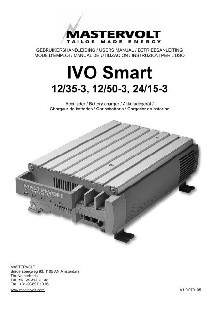
OVERALL PICTURE<br />
1 AC mains cable 8 Remove jumper for force float<br />
2 Positive battery terminal #1 9<br />
3 Positive battery terminal #2 10<br />
4 Negative battery terminal 11 LED Bulk charge<br />
Remove jumper for gel/AGM/spiral<br />
setting<br />
Remove jumper for diode<br />
compensation<br />
5 Slave battery terminal 12 LED Absorption charge<br />
6 Digital modular jack 13 LED Float charge<br />
7 Analogue modular jack<br />
1<br />
5<br />
6 7<br />
Figure 4: Overall picture<br />
2<br />
8 9<br />
3 4<br />
10<br />
13<br />
12<br />
11
SPECIFICATIONS <strong>IVO</strong> SMART<br />
Model <strong>IVO</strong> <strong>Smart</strong> 12/35-3 <strong>IVO</strong> <strong>Smart</strong> 12/50-3 <strong>IVO</strong> <strong>Smart</strong> 24/15-3<br />
Article no. 43013500 43015000 43021530<br />
DC<br />
Charge voltage BULK (25°C) 14.40VDC 14.40VDC 28.80VDC<br />
Charge voltage ABSORPTION (25°C) 14.25VDC 14.25VDC 28.50VDC<br />
Charge voltage FLOAT (Wet; 25°C) 13.25VDC 13.25VDC 26.50VDC<br />
Charge voltage FLOAT (Gel; 25°C) 13.80VDC 13.80VDC 27.60VDC<br />
Total charge current 35A 50A 15A<br />
DC consumption with connected battery
CE DECLARATION OF CONFIRMITY<br />
Manufacturer: Mastervolt B.V.<br />
Herewith declares that:<br />
Snijdersbergweg 93<br />
1105 AN Amsterdam<br />
The Netherlands<br />
Product: <strong>IVO</strong> <strong>Smart</strong> 12/35-3<br />
<strong>IVO</strong> <strong>Smart</strong> 12/50-3<br />
<strong>IVO</strong> <strong>Smart</strong> 24/15-3<br />
Is in conformity with the following provisions of the EC:<br />
EMC directive EMC 89/336/EEG and amendments 92/31/EEC and 93/68/EEC.<br />
The following harmonized standards have been applied:<br />
Generic emission standard: EN 50081-1:1992<br />
Generic Immunity standard: EN 50082-1:1997<br />
Safety directive 73/23/EEC and amendment 93/68/EEC, with the following standard:<br />
Low voltage standard: EN 60950: 2000<br />
Amsterdam,<br />
R.J. ter Heide,<br />
Managing Director MASTERVOLT
NOTES
NOTES
Snijdersbergweg 93, 1105 AN Amsterdam, The Netherlands<br />
Tel : + 31-20-3422100<br />
Fax : + 31-20-6971006<br />
Email : info@mastervolt.com