Aeroquip - Powerflex-fhp
Aeroquip - Powerflex-fhp
Aeroquip - Powerflex-fhp

Create successful ePaper yourself
Turn your PDF publications into a flip-book with our unique Google optimized e-Paper software.
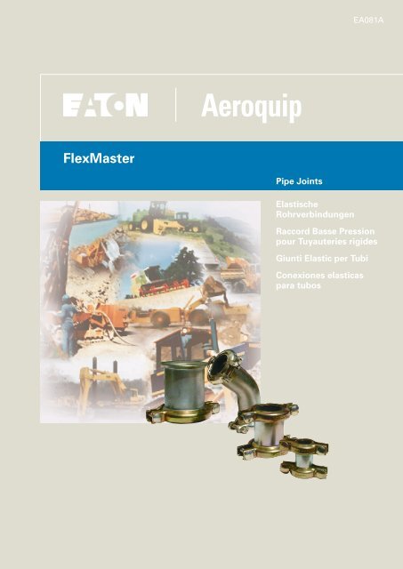
FlexMaster<br />
<strong>Aeroquip</strong><br />
Pipe Joints<br />
Elastische<br />
Rohrverbindungen<br />
EA081A<br />
Raccord Basse Pression<br />
pour Tuyauteries rigides<br />
Giunti Elastic per Tubi<br />
Conexiones elasticas<br />
para tubos
The concept<br />
The FLEXMASTER range consists of tube/<br />
pipe joints for the low pressure application.<br />
There are ideal for producing leak-proof<br />
connections between pipe ends. They can<br />
also provide compensation for alignment<br />
errors of pipes in installations and can<br />
absorb relative movement of pipes.<br />
The connector consists of 7 metal<br />
components, 2 sealing rings and 4 bolts<br />
with self-locking nuts.<br />
The most important components for correct<br />
operation of FLEXMASTER pipe joints are<br />
the two sealing rings. They have the<br />
following functions:<br />
1. Sealing up to an operating pressure of<br />
max.15 bar with all connectors in<br />
product range (see page 12).<br />
2. Compensation of possible alignment<br />
errors of pipes to be connected up to<br />
±2°.<br />
3. Compensation for or absorption of<br />
vibration.<br />
4. Absorption to a certain degree of axial<br />
displacements of pipes caused by<br />
temperature fluctuations or external<br />
mechanical influences.<br />
5. Chemical resistance to media specified<br />
by us.<br />
Standard designs of FLEXMASTER are<br />
supplied with sealing rings made of<br />
perburian (NBR). These can be used with<br />
commercial mineral oils and water at<br />
temperatures from -40°C to +110°C (for<br />
brief periods also up to +120°C). With hot<br />
air, these sealing rings can be used only at<br />
temperatures up to +70°C (see also<br />
temperature table on page 12).<br />
Special sealing rings made of fluorelastomer<br />
(FPM) are available for use at higher<br />
medium temperatures of up to +230°C.<br />
2<br />
Das Konzept<br />
FLEXMASTER sind elastische Rohrverbindungen<br />
für den Niederdruckbereich.<br />
Sie sind ideale Bauelemente um Rohrenden<br />
dicht miteinander zu verbinden. Darüber<br />
hinaus können sie Fluchtversatz von Rohren<br />
in Anlagen ausgleichen und Bewegungen<br />
der Rohre zueinander aufnehmen.<br />
Die Verbindung besteht aus 7 Metallteilen,<br />
2 Dichtringen und 4 Schrauben mit selbstsichernder<br />
Mutter.<br />
Wichtigste Teile für eine einwandfreie Funktion<br />
der elastischen Rohrverbindung<br />
FLEXMASTER sind die beiden Dichtringe.<br />
Sie haben folgende Aufgaben zu erfüllen.<br />
1. Bis zu einem Betriebsdruck von max.<br />
15 bar in allen Ausführungen zu dichten<br />
(siehe Seite 12).<br />
2. Eine mögliche Fluchtabweichung der zu<br />
verbindenden Rohre bis max. ±2° auszugleichen.<br />
3. Vibrationen zu kompensieren oder zu<br />
dämpfen.<br />
4. Axiale Verschiebungen der Rohre durch<br />
Temperaturschwankungen oder äußere<br />
mechanische Einflüsse begrenzt aufzunehmen.<br />
5. Chemisch beständig gegen die von uns<br />
genannten Medien zu sein.<br />
In der Standardausführung werden FLEX-<br />
MASTER mit Dichtringen aus Perbunan<br />
(NBR) geliefert. Sie sind für handelsübliche<br />
Mineralöle und Wasser mit Temperaturen<br />
von -40°C bis +110°C (kurzzeitig auch bis<br />
+120°C) einsetzbar. Für Heißluft können<br />
diese Dichtringe nur für Temperaturen bis<br />
+70°C verwendet werden (siehe auch<br />
Temperaturtabelle Seite 12).<br />
Für den Einsatz bei höheren Medium-Temperaturen<br />
bis +230°C sind Spezialdichtringe<br />
aus Fluorelastomer (FPM) lieferbar.
Principe<br />
Le FLEXMASTER est un raccord basse<br />
pression pour tuyauteries rigides. Il permet<br />
de compenser le mauvais alignement des<br />
tubes, ainsi que d’éventuelles variations<br />
dues aux vibrations ou à la dilatation, tout<br />
en conservant une parfaite étanchéité.<br />
Le raccord FLEXMASTER est constitué de<br />
7 parties métalliques, 2 joints d’étanchéité<br />
et 4 vis avec écrous auto-bloquants.<br />
Les pièces essentielles du raccord sont,<br />
bien sûr, les deux joints qui sont conçus<br />
pour assurer les fonctions suivantes:<br />
1. Garantie d’étanchéité, jusqu’à une<br />
pression de service de 15 bar, et ce,<br />
dans toutes les conditions normales<br />
d’utilisation.<br />
2. Compenser les défauts d’alignement des<br />
tubes à raccorder, jusqu’à un écart<br />
maximum de ± 2°.<br />
3. Amortir les vibrations.<br />
4. Compenser, dans une certaine mesure,<br />
un déplacement axial des tubes, dû à<br />
des variations de température ou à des<br />
contraintes mécaniques externes.<br />
5. Résister aux fluides véhiculés.<br />
En exécution standard, les raccords<br />
FLEXMASTER sont livrés avec des joints en<br />
Nitrile (NBR) qui conviennent pour les<br />
applications courantes (eau, huiles minérales)<br />
à des températures variant entre –<br />
40°C et + 110°C (pointes éventuelles à<br />
+120°C). Pour l’air chaud la température<br />
maximum admissible est de +70°C.<br />
Sur demande, nous pouvons livrer des<br />
joints d’étanchéité spéciaux en élastomère<br />
fluoré (FPM), pour des températures allant<br />
jusqu’à +230°C.<br />
Il principio<br />
I FLEXMASTER sono giunti flessibili per tubi<br />
ideati per il range di bassa pressione e<br />
costituiscono la soluzione ideale per<br />
ottenere un collegamento assolutamente<br />
ermetico delle estremità dei tubi. Inoltre,<br />
questi giunti sono in grado di compensare<br />
l’errore di allineamento dei tubi negli<br />
impianti nonché di assorbire i movimenti<br />
relativi dei tubi.<br />
Il giunto si compone di 7 elementi metallici,<br />
2 anelli di tenuta e 4 viti con dado<br />
autobloccante.<br />
Gli elementi principali per garantire il<br />
perfetto funzionamento del giunto elastico<br />
FLEXMASTER sono i due anelli di tenuta, i<br />
quali sono preposti alle seguenti funzioni:<br />
1. Garantire la tenuta sino ad una<br />
pressione d’esercizio max. di 15 bar in<br />
qualsiasi versione (vedi pagina 13).<br />
2. Compensare un eventuale errore di<br />
allineamento dei tubi da collegare sino<br />
ad un max. di ± 2°.<br />
3. Compensare ovvero assorbire le<br />
vibrazioni.<br />
4. Assorbire sino ad un certo grado gli<br />
spostamenti assiali dei tubi dovuti ad<br />
oscillazioni di temperatura oppure ad<br />
altri fenomeni meccanici esterni.<br />
5. Resistere agli agenti chimici da noi<br />
indicati.<br />
Nella versione standard, i giunti FLEX-<br />
MASTER vengono forniti provvisti di anelli<br />
di tenuta in perbuna (gomma acriliconitrilica<br />
NBR) e possono essere utilizzati per<br />
gli oli minerali tradizionali presenti in<br />
commercio nonché per l’acqua a<br />
temperature comprese tra –40°C e +110°C<br />
(per breve tempo anche sino a +120°C).<br />
Per quanto riguarda l’aria calda, gli anelli<br />
di tenuta forniti in dotazione possono<br />
essere impiegati soltanto per temperature<br />
fino a +70°C (vedi anche la tabella delle<br />
temperature riportata a pagina 13).<br />
El Concepto<br />
FLEXMASTER son conexiones elásticas de<br />
tubos en el campo de la baja presión. Se<br />
trata de elementos de construcción ideales<br />
para conseguir una hermeticidad<br />
absoluta en la unión de tuberías rígidas.<br />
Además se tiene la ventaja de corregir el<br />
desalineamiento de los tubos en las<br />
instalaciones dada la elasticidad de las<br />
conexiones.<br />
La conexión consta de 7 partes metálicas,<br />
2 anillos de junta y 4 tonillos con tuerca<br />
auto-ajustables.<br />
Partes importantes para un perfecto<br />
funcionamiento de las conexiones<br />
elásticas FLEXMASTER son los dos anillos<br />
de junta. Estos cumplen los siguientes<br />
cometidos:<br />
1. Garantizar la estanqueidad hasta una<br />
presión de servicio de máx. 15 bar en<br />
todos los modelos suministrables.<br />
2. Compensar una posible desalineación<br />
de los tubos hasta máx. ± 2°.<br />
3. Compensar las vibraciones o amortiguarlas.<br />
4. Evitar desplazamientos exiales de los<br />
tubos para variaciones de temperatura<br />
o por influencia mecánica.<br />
5. Químicamente estable en las condiciones<br />
de servicio que indicamos.<br />
En la presentación Standard los<br />
FLEXMASTER se suministran con anillos de<br />
junta de Perbunán (NBR) y son aplicables<br />
para la conducción de aceites minerales<br />
convencionales y agua con temperaturas<br />
de –40°C hasta +110°C (en cortos<br />
intervalos también hasta +120°C). Para aire<br />
caliente, estos anillos solamente se<br />
pueden utilizar hasta 70°C de temperatura.<br />
Para su empleo a otras temperaturas hasta<br />
230°C suministramos anillos de junta<br />
especiales de Fluorelastómero (FPM).<br />
3
Possible applications<br />
Many branches of industry use pipe/tube<br />
joints for pipeline construction. The<br />
following table lists some of the most<br />
common possible applications for <strong>Aeroquip</strong><br />
FLEXMASTER but is naturally not<br />
exhaustive. The table is intended merely<br />
to provide designers with suggestions for<br />
the solution to pipeline-construction<br />
problems.<br />
User Application<br />
Large engine Cooling-water,<br />
construction cooling-air<br />
systems<br />
Large gear unit Pipe/tube<br />
construction connection<br />
Railway rolling- Piping systems<br />
stock and for cooling water,<br />
locomotive air supply<br />
construction,<br />
shipbuilding<br />
Heavy machine Coolant lines,<br />
construction suction lines<br />
Construction Hydraulic lines<br />
machinery, in low-pressure<br />
machine tools, pumps, and suction systems<br />
conveyor systems,<br />
general machine<br />
construction<br />
Chemical plant Lines for waterconstruction<br />
treatment systems<br />
and similar<br />
Power-station General piping<br />
construction systems<br />
and boilermaking<br />
Compressor Connection of air<br />
construction lines<br />
Refineries Piping for supply<br />
systems<br />
Repair workshops, Repair of defective<br />
fitters, etc. pipelines without<br />
welding e. g. in<br />
cases where<br />
explosion hazard is<br />
present<br />
4<br />
In cases where it is planned to use<br />
FLEXMASTER in a piping system, the first<br />
step must be to answer the following<br />
questions:<br />
1. How high is the maximum pressure?<br />
2. What compensation is required for<br />
alignment errors of the pipe ends?<br />
3. How large will the axial movements<br />
of the pipes be?<br />
4. What frequencies must be expected<br />
(e. g. with motor cooling systems)?<br />
5. What medium and what temperature<br />
are to be used in the installation?<br />
The following pages are intended to help<br />
you plan the use of FLEXMASTER pipe<br />
connectors correctly with regard to these<br />
factors and to ensure that the connectors<br />
will operate satisfactorily when fitted.
Anwendungsmöglichkeiten<br />
Viele Branchen verwenden im Leitungsbau<br />
elastische Rohrverbindungen. Die folgende<br />
Tabelle führt einige der häufigsten<br />
Einsatzmöglichkeiten für <strong>Aeroquip</strong> FLEX-<br />
MASTER auf, ist aber verständlicherweise<br />
nicht erschöpfend. Ihre Aufgabe kann deshalb<br />
nur sein, dem Konstrukteur Anregungen<br />
zur Lösung von Leitungsproblemen zu<br />
geben.<br />
Anwender Einsatz<br />
Großmotorenbau Kühlwasser-,<br />
Kühlluft-<br />
Systeme<br />
Großgetriebebau Verbindungsleitungen<br />
Waggon- und Lokbau, Rohrsysteme<br />
Schiffsbau Kühlwasser,<br />
Luftversorgung<br />
Schwermaschinenbau Kühlmittelleitungen,<br />
Saugleitungen<br />
Baumaschinen, für Hydraulik-<br />
Werkzeugmaschinen, leitungen<br />
Pumpen, in Niederdruck-<br />
Förderanlagen, und Saugsystemen<br />
allgemeiner<br />
Maschinenbau<br />
Chem. Apparatebau Leitungen für<br />
Wasseraufbereitung<br />
u. ä.<br />
Kraftwerk- Rohrsysteme<br />
und Kesselbau allgemein<br />
Kompressorenbau Verbindung von<br />
Luftleitungen<br />
Raffinerien Rohrleitungsbau<br />
für Versorgungsleitungen<br />
Reparaturwerkstätten, Reparatur von<br />
Installateure etc. defekten Rohrleitungen<br />
- ohne<br />
Schweißen,<br />
z.B. bei Explosionsgefahr<br />
Wenn in einem Leitungssystem<br />
FLEXMASTER eingesetzt werden soll, ist von<br />
folgenden Fragen auszugehen:<br />
1. Wie hoch liegt der Maximal-Druck?<br />
2. Welcher Fluchtversatz der Rohrenden<br />
ist zu überbrücken?<br />
3. Wie groß werden die Axialbewegungen<br />
der Rohre sein?<br />
4. Welche Frequenzen sind zu erwarten<br />
(z. B. an Motor-Kühlsystemen)?<br />
5. Mit welchem Medium und mit welcher<br />
Temperatur wird die Anlage gefahren?<br />
Die folgenden Seiten sollen Ihnen helfen,<br />
den Einsatz von FLEXMASTER-<br />
Rohrverbindungen unter diesen Gesichtspunkten<br />
richtig zu planen und ihre betriebssichere<br />
Funktion in der Praxis sicherzustellen.<br />
5
Exemples d’utilisations<br />
De très nombreux secteurs industriels<br />
peuvent utiliser les FLEXMASTER<br />
AEROQUIP pour le raccordement de leurs<br />
tuyauteries rigides. Le tableau ci-dessous<br />
décrit quelques-unes des utilisations les<br />
plus courantes. Il n’est bien sûr pas<br />
exhaustif, mais peut donner quelques idées<br />
pour solutionner des problèmes des<br />
raccordement.<br />
Domaines Applications<br />
d’utilisation<br />
Construction de Circuit de<br />
gros moteurs refroidissement par<br />
huile ou par eau.<br />
Construction de Circuits de liaison.<br />
gros réducteurs<br />
Construction de Circuits de<br />
matériel ferroviaire refroidissement, et<br />
Construction navale d’aération.<br />
Construction Conduites de<br />
mécanique lourde refroidissement et<br />
d’aspiration.<br />
Construction Circuits<br />
de matériel destiné pour la préparation<br />
à l’industrie chimique de l’eau par<br />
example.<br />
Construction de Canalisations en<br />
contrales électriques général.<br />
et de chaudières<br />
Construction de Raccordement des<br />
compresseurs canalisations d’air.<br />
Raffineries Tuyauteries<br />
d’alimentation.<br />
Ateliers de Réparation de<br />
réparations, conduites<br />
installations dèfectueuses, sans<br />
sanitaires, etc. soudure, par<br />
example : en cas de<br />
risque d’explosion.<br />
6<br />
Pour exploiter au mieux les possibilités du<br />
raccord FLEXMASTER AEROQUIP, l’utilisateur<br />
devra obtenir les<br />
informations suivantes :<br />
1. Quelle est la pression maximum ?<br />
2. Quel est l’écart d’alignement entre<br />
les tubes ?<br />
3. Quel est le déplacement axial des<br />
tubes ?<br />
4. Quelles sont les fréquences de<br />
vibrations prévues (par exemple sur<br />
une conduite de refroidissement de<br />
moteur) ?<br />
5. Quels sont les fluides véhiculés et à<br />
quelle température ?<br />
Les indications données dans les pages<br />
suivantes vous aideront dans le choix du<br />
raccord FLEXMASTER en fonction des<br />
questions ci-dessus, afin de garantir un<br />
fonctionnement sûr.<br />
Le possibilità di applicazione<br />
Diversi settori dell’industria utilizzano giunti<br />
elastici per la costruzione di tubazioni. La<br />
seguente tabella riporta alcune delle<br />
possibilità di applicazione più frequenti per<br />
i giunti FLEXMASTER di <strong>Aeroquip</strong> ma,<br />
ovviamente, non intende essere esauriente,<br />
bensì fornire al costruttore alcuni<br />
suggerimenti utili per risolvere i diversi<br />
problemi di costruzione.<br />
Utente Applicazione<br />
Costruzione di grandi Sistemi acqua<br />
motori di raffreddamento,<br />
aria di<br />
raffreddamento<br />
Costruzione di grandi Tubazioni di<br />
gruppi meccanici collegamento<br />
Costruzione di Sistemi di tubazioni<br />
materiale rotabile per acqua<br />
e locomotive, di raffreddamento,<br />
costruzione navale alimentazione aria<br />
Costruzione di Tubazioni e<br />
macchine pesanti refrigerante, linee<br />
di aspirazione<br />
Meccanica, macchine per tubazioni<br />
utensili, pompe, idrauliche nei<br />
impianti trasportatori, sistemi a bassa<br />
meccanica generale pressione e di<br />
aspirazione<br />
Costruzione di Tubazioni per la<br />
impianti chimici depurazione dell’acqua<br />
e simili<br />
Costruzione di centrali Sistemi di tubazioni<br />
elettriche e caldaie in generale<br />
Costruzione di Collegamento delle<br />
compressori tubazioni dell’aria<br />
Raffinerie Tubazioni per i sistemi<br />
di alimentazione<br />
Officine di riparazione, Riparazione di<br />
installatori ecc. tubazioni difettose<br />
– senza saldatura,<br />
ad esempio in<br />
presenza di pericolo<br />
di esplosione
Prima di installare i giunti FLEXMASTER in<br />
un sistema di tubazioni sarà necessario<br />
porsi le seguenti domande:<br />
1. Qual è il valore pressorio massimo?<br />
2. Che compensazione è richiesta per<br />
gli errori di allineamento delle<br />
estremità dei tubi?<br />
3. Di che entità sono i movimenti assiali<br />
dei tubi?<br />
4. Quali frequenze sono previste (ad<br />
esempio nei sistemi di raffreddamento<br />
dei motori)?<br />
5. Con quale mezzo e a quale<br />
temperatura viene utilizzato<br />
l’impianto?<br />
Le seguenti pagine forniscono alcuni<br />
suggerimenti per realizzare una corretta<br />
installazione dei giunti FLEXMASTER<br />
tenendo in considerazione i punti succitati<br />
nonché per garantire il perfetto<br />
funzionamento dei giunti una volta montati.<br />
La posibilidades de aplicación<br />
En muchas ramas de la industria se<br />
emplean las conexiones elásticas. La tabla<br />
siguiente presenta las aplicaciones más<br />
usuales de los FLEXMASTER de <strong>Aeroquip</strong>,<br />
pero existen muchas más. Su objetivo es<br />
solamente darle al Constructor iniciativas<br />
para solucionar sus problemas de<br />
conducciones.<br />
Campo Empleo<br />
de aplicación<br />
Fabricación Agua fría, aire frío<br />
de motores<br />
Fabricación de Conducciones<br />
engranajes<br />
Construcción de Sistemas de tubo<br />
vagones, locomotoras para, agua<br />
y construcción naval refrigerante,<br />
abastecimiento<br />
de aire<br />
Construcción de Conductos de<br />
máquinas pesadas refrigerante, tubería<br />
de aspiración<br />
Máquinas para la Para las<br />
construcción, conduciones<br />
máquinas herra- hidráulicas y de<br />
mientas, bombas, baja presión<br />
instalaciones y sistema de<br />
transportadoras, aspiración<br />
fabricación de<br />
maquinaria en<br />
general<br />
Fabricación de Conducciones para<br />
aparatos para la el tratamiento de<br />
industria química aguas, etc.<br />
Construcción de Sistema de tuberías<br />
centrales térmicas en general<br />
Construcción de Conexiones de concalderas<br />
ducciones de aire<br />
Fabricación de Conducciones de<br />
compresores alimentación<br />
Refinerías, Talleres Reparación de conde<br />
reparación, ducciones de tubeinstalaciones,<br />
etc. ría defect uosas, sin<br />
soldadura, p.e.<br />
cuando existe peligro<br />
de explosión<br />
Cuando instalamos un sistema de<br />
conducción FLEXMASTER debemos partir<br />
de la respuesta a las siguientes<br />
Preguntas:<br />
1. A qué punto llega la presión máxima?<br />
2. Con qué desalineación debemos<br />
contar?<br />
3. Cómo son los movimientos exiales<br />
de los tubos?<br />
4. Qué frecuencias se esperan? (p.e. en<br />
el sistema de refrigeración de un<br />
motor)<br />
Las páginas siguentes le ayudarán a planear<br />
correctamente la aplicación de las conexiones<br />
de tubos FLEXMASTER y le<br />
asegurarán un perfecto funcionamiento de<br />
servicio en la práctica.<br />
7
Planning and routing<br />
In order to obtain correct operation after<br />
installation, the following should be taken<br />
into account when planning piping systems:<br />
FLEXMASTER pipe joints must always be<br />
installed in such a way that they are<br />
accessible for periodic inspection.<br />
During routing, it must be possible to push<br />
the FLEXMASTER sleeve onto the ends of<br />
the pipes to be connected before the pipes<br />
are permanently installed. The length “L”<br />
should therefore be chosen in such a way<br />
that the minimum pipe-to-pipe distance “k”<br />
is sufficiently large to allow replacement<br />
of sealing rings without dismantling the<br />
pipes. Care should be taken to maintain<br />
the minimum insertion depth of the pipe<br />
ends “g” (see pages 8-11).<br />
At installation angles more than 45° to the<br />
vertical, FLEXMASTER must be secured by<br />
clips to prevent slipping.<br />
During the routing of the elbow design of<br />
FLEXMASTER (45° or 90°), care must be<br />
taken with high liquid velocities to position<br />
the pipe support as close as possible to<br />
the pipe ends. The fitting of an additional<br />
support to prevent pulling away will ensure<br />
trouble-free operation even where high<br />
pulling away forces are present.<br />
8<br />
Projektierung und<br />
Verlegung<br />
Mit Rücksicht auf einwandfreie Funktion<br />
nach der Montage ist schon während der<br />
Projektierung der Leitungen folgendes zu<br />
beachten:<br />
FLEXMASTER Rohrverbindungen werden<br />
immer so eingebaut, daß sie für eine Inspektion<br />
in gewissen Zeitabständen zugänglich<br />
sind.<br />
Bei der Verlegung soll die FLEXMASTER-<br />
Hülse auf die zu verbindenden Rohrenden<br />
geschoben werden können, bevor die Rohre<br />
fest installiert sind. Die Länge “L” ist also<br />
so zu wählen, daß der Mindest-Rohrabstand<br />
“k” groß genug ist, um Dichtringe ohne Lösen<br />
der Rohre auswechseln zu können.<br />
Hierbei ist die Mindest-Eintauchtiefe der<br />
Rohrenden “g” (s. Seiten 8-11) einzuhalten.<br />
Ab 45° bis zu senkrechtem Einbau muß<br />
der FLEXMASTER gegen Verrutschen durch<br />
eine Schelle gesichert werden.<br />
Bei der Verlegung von FLEXMASTER in Ausführung<br />
als Krümmer (45° oder 90°) muß<br />
bei hohen Flüssigkeits-Geschwindigkeiten<br />
die Halterung der Rohrenden so nah wie<br />
möglich an der Verbindung liegen. Eine zusätzliche<br />
Halterung als Abzugssicherung anzubringen,<br />
gewährleistet störungsfreien Betrieb<br />
auch bei hohen Abzugskräften.
Conception et<br />
installation<br />
Pour garantir une parfaite utilisation après<br />
installation, il sera nécessaire, lors d’une<br />
étude d’installation, de respecter les règles<br />
suivantes :<br />
Les raccords FLEXMASTERR devront rester<br />
accessibles pour des inspections<br />
régulières.<br />
Au montage, le raccord FLEXMASTER doit<br />
pouvoir être glissé sur les tubes à raccorder<br />
avant leur fixation définitive. La longueur<br />
„L“ devra être définie de façon que l’écart<br />
minimum „k“, entre les deux tubes, soit<br />
suffisant pour permettre le changement<br />
des joints sans démontage de toute la<br />
tuyauterie. On devra aussi respecter la cote<br />
de pénétration minimum „g“ (voir pages 8<br />
à 11).<br />
Pour des montages compris entre 45° et la<br />
verticale, il est nécessaire de prévenir le<br />
glissement du raccord par la pose d’un<br />
collier de fixation.<br />
Lors de l’installation de FLEXMASTER<br />
coudés (à 45° ou 90°), on devra, pour des<br />
vitesses de fluide élevées, prévoir la<br />
fixation des tubes le plus près possible du<br />
raccord. Une fixation supplémentaire<br />
empêchera tout déboîtement, même sous<br />
des efforts de traction importants.<br />
Progettazione e<br />
installazione<br />
Per ottenere un perfetto funzionamento<br />
anche dopo l’installazione è necessario<br />
osservare quanto segue già durante la fase<br />
di progettazione delle tubazioni:<br />
I giunti FLEXMASTER devono sempre<br />
essere installati in modo da essere<br />
accessibili per le necessarie ispezioni ad<br />
intervalli regolari.<br />
Durante la posa, il manicotto FLEXMASTER<br />
deve poter essere spinto sulle estremità<br />
da collegare prima che i tubi siano installati<br />
definitivamente. La lunghezza ”L”, quindi,<br />
dovrà essere stabilita in modo tale che la<br />
distanza minima ”k” sia sufficiente da<br />
consentire di sostituire gli anelli di tenuta<br />
senza staccare i tubi. Inoltre, occorre<br />
attenersi scrupolosamente alla profondità<br />
minima di inserimento delle estremità dei.<br />
Da un’angolazione di 45° sino alla posa in<br />
verticale, il giunto FLEXMASTER dovrà<br />
essere fissato con fascette stringitubo<br />
affinché non scivoli.<br />
Per la posa dei giunti FLEXMASTER in<br />
versione a gomito (45° oppure 90°) su<br />
tubazioni in cui il fluido scorre ad alta<br />
velocità, il supporto del tubo deve essere<br />
posizionato il più vicino possibile alle<br />
estremità dei tubi. Applicando un ulteriore<br />
supporto che eviti il distacco dei tubi, si<br />
garantisce un funzionamento perfetto<br />
anche in presenza di elevate forze di<br />
trazione.<br />
Proyecto de instalación<br />
Con vistas a una función correcta de la<br />
instalación hay que observar los siguientes<br />
puntos ya durante la fase de proyecto.<br />
Las conexiones FLEXMASTER siempre se<br />
instalarán de forma que sean accesibles a<br />
cualquier inspección.<br />
Al colocar los tubos siempre debe ser<br />
posible el deslizamiento del FLEXMASTER<br />
en sus extremos, los cuales deben ser<br />
conectados antes de la instalación<br />
definitiva de los conductos. Por ello hay<br />
que preveer la longitud “L” de forma que<br />
la distancia mínima “K” sea lo suficiente<br />
para hacer posible el cambio de las<br />
empaquetaduras sin desplazar los tubos.<br />
En hesto hay que tener presente la<br />
profundidad mínima de introducción de los<br />
extremos de los tubos “g” (ver pág. 8-11).<br />
En instalaciones verticales de FLEXMASTER<br />
recto o a 45° hay que asegurar éste con<br />
una abrazadera contra posibles<br />
desplazamientos.<br />
Al instalar FLEXMASTER acodados (45° ó<br />
90°) el dispositivo de fijación de los tubos<br />
con grandes velocidades de líquidos debe<br />
situarse lo más cerca posible de la<br />
conexión. La instalación de un dispositivo<br />
fijador adicional como muestra la figura,<br />
asegura un funcionamiento sin perturbaciones,<br />
aun con gran fuerza de flujo.<br />
9
Technical data<br />
Alignment errors,<br />
absorption of movement<br />
If an alignment error (V) of the pipes to be<br />
connected is present, the FLEXMASTER<br />
sleeve must not touch the pipe ends. The<br />
permissible alignment error is determined<br />
by the insertion depth of the pipe ends (g)<br />
and the permissible angle of ±2° (see<br />
illustration and graph).<br />
All sizes of FLEXMASTER are designed in<br />
such a way as to allow an alignment error of<br />
±2°. However, if this is exceeded, an<br />
appropriately longer FLEXMASTER sleeve<br />
must be selected. This must also be done<br />
in cases where pipes in intrinsically correct<br />
alignment could be misaligned by vibration.<br />
The illustration opposite shows how to<br />
determine the FLEXMASTER length “L” in<br />
relation to “V 1 ” and “V 2 ” while maintaining<br />
an angle of ±2°.<br />
Straight designs of FLEXMASTER are<br />
available up to a maximum length “L” of<br />
1000 mm. If a total length of more than<br />
1000 mm is essential, please use 2<br />
FLEXMASTER connectors with an intermediate<br />
pipe section. This intermediate pipe<br />
section must be supported.<br />
The pipes to be used must have wall thicknesses<br />
at least equal to those listed opposite<br />
to ensure that they are not deformed<br />
by any movements which occur.<br />
The pipe ends must have a smooth surface<br />
at least at the seal seats in order to ensure<br />
correct operation (see also page 22).<br />
Ext. pipe dia. Ø Wall thickness<br />
12- 25 mm 1,0 mm<br />
18-120 mm 1,5 mm<br />
10<br />
Technische Angaben<br />
Fluchtversatz,<br />
Bewegungsaufnahme<br />
Bei Fluchtversatz (V) der zu verbindenden<br />
Rohre darf die FLEXMASTER-Hülse die Rohrenden<br />
nicht berühren. Die zulässige Größe<br />
des Fluchtversatzes wird bestimmt durch die<br />
Eintauchtiefe der Rohrenden (g) und dem<br />
zulässigen Winkel von ±2° (siehe Abbildung<br />
mit Diagramm).<br />
Alle FLEXMASTER-Größen sind so konstruiert,<br />
daß ein Versatzwinkel von ±2° möglich<br />
ist. Ist der Fluchtversatz größer, so daß<br />
bei gegebenem Abstand der Rohrenden dieser<br />
Winkel überschritten würde, dann muß<br />
die FLEXMASTER-Hülse entsprechend länger<br />
gewählt werden. Dies gilt ebenso, wenn<br />
an sich fluchtende Rohre durch Schwingungen<br />
versetzt werden können.<br />
Die Bestimmung der FLEXMASTER-Länge<br />
“L” in Abhängigkeit von der Differenz zwischen<br />
“V 1 ” und “V 2 ” unter Beibehaltung des<br />
Winkels von ±2° ist in der Abbildung dargestellt.<br />
FLEXMASTER in gerader Ausführung sind bis<br />
zu einer Länge “L” max. 1000 mm lieferbar.<br />
Ist eine Gesamtlänge von mehr als 1000<br />
mm unvermeidbar, so verwenden Sie bitte<br />
2 FLEXMASTER mit einem Zwischenrohr.<br />
Das Zwischenrohr ist zu haltern.<br />
Die zu verwendenden Rohre dürfen die<br />
nachstehend aufgeführten Wandstärken<br />
nicht unterschreiten, damit sie bei auftretenden<br />
Bewegungen nicht verformt werden.<br />
Zumindest an den Dichtungssitzen müssen<br />
die Rohrenden eine glatte Oberfläche haben,<br />
wenn störungsfreie Funktion gewährleistet<br />
sein soll (vgl. Seite 22).<br />
Rohr-Außen-Ø Wandstärke<br />
12- 25 mm 1,0 mm<br />
18-120 mm 1,5 mm
Informations techniques<br />
Débattement angulaire –<br />
Compensation des<br />
mouvements<br />
En casi de débattement angulaire des tubes<br />
à raccorder, le corps du FLEXMASTER ne<br />
devra, en aucun cas, entrer en contact avec<br />
leurs extrémités. La valeur maximale de<br />
débattement angulaire est donnée par la<br />
cote minimale de pénétration « g » et par<br />
l’angle maximal admissible de ± 2° (voir<br />
figure et diagramme).<br />
Tous les FLEXMASTER sont conçus pour<br />
permettre un débattement angulaire de ± 2°.<br />
Si pour un FLEXMASTER standard, l’écart<br />
entre les tubes est trop important, il y aura<br />
lieu de prévoir un corps de raccord plus long<br />
afin de conserver l’angle maximum de 2°.<br />
Cette remarque vaut également pour les cas<br />
où l’alignement des tubes peut être modifié<br />
par les vibrations.<br />
La longueur « L » du FLEXMASTER dépend<br />
du débattement V des tuyauteries rigides.<br />
Le dessin ci-contre montre bien quà L 1<br />
correspond un débattement V 1 et quà L 2<br />
correspond un débattement V 2 , l’angle de<br />
2° restant le même.<br />
Le débattement V maximum est de 40 mm<br />
et la longueur « L » maximum de fabrication<br />
est de 1000 mm. Si le débattement est trop<br />
important on pourra réaliser le<br />
raccordement en disposant une entretoise<br />
fixe entre deux FLEXMASTER.<br />
L‘épaisseur des tubes à raccorder ne devra<br />
pas être inférieure à la valeur indiquée cicontre,<br />
afin d’éviter leur déformation en cas<br />
de mouvements éventuels (vibrations,<br />
dilatations, etc.).<br />
La surface extérieure des tubes devra être<br />
lisse, au moins sur les zones d’appui des<br />
joints d’étanchéité (voir également page 23).<br />
Ø de la tuyauterie Epaisseur<br />
12- 25 mm 1,0 mm<br />
18-120 mm 1,5 mm<br />
Specifiche tecniche<br />
Errore di allineamento,<br />
assorbimento dei<br />
movimenti<br />
In caso di errore di allineamento (V) dei tubi<br />
da collegare, il manicotto FLEXMASTER non<br />
deve toccare le estremità del tubo. Il valore<br />
massimo consentito per l’errore di<br />
allineamento viene determinato dalla<br />
profondità d’inserimento delle estremità del<br />
tubo (g) e dall’angolazione massima di ± 2°<br />
(vedi figura con grafico).<br />
Tutte le misure dei giunti FLEXMASTER sono<br />
state concepite in modo da consentire un<br />
errore di allineamento di ± 2°. Tuttavia, se<br />
questa tolleranza venisse superata anche<br />
rispettando la distanza prestabilita tra le<br />
estremità del tubo, si dovrà scegliere un<br />
giunto FLEXMASTER corrispondentemente<br />
più lungo. Ciò vale anche nei casi in cui tubi<br />
correttamente allineati venissero disallineati<br />
a causa delle vibrazioni.<br />
La figura illustra il modo in cui viene stabilita<br />
la lunghezza ”L” per il giunto FLEXMASTER<br />
in funzione della differenza tra ”V 1 ” e ”V 2 ”<br />
mantenendo un’angolazione di ± 2°.<br />
I giunti FLEXMASTER in versione diritta sono<br />
disponibili in lunghezze ”L” massime di<br />
1000 mm, quindi, si dovranno utilizzare 2<br />
giunti FLEXMASTER con un tubo intermedio,<br />
che dovrà essere idoneamente sostenuto.<br />
Onde evitare un’eventuale deformazione dei<br />
tubi in caso di movimenti, lo spessore da<br />
utilizzare non deve essere inferiore a quello<br />
indicato nella figura a fianco.<br />
Per garantire un funzionamento perfetto, le<br />
estremità del tubo devono presentare una<br />
superficie levigata, almeno dove poggiano<br />
gli anelli di tenuta (cfr. pagina 23).<br />
Diam. esterno tubo Spessore<br />
12- 25 mm 1,0 mm.<br />
18-120 mm 1,5 mm.<br />
Datos Técnicos,<br />
desalineamiento,<br />
elasticidad de las<br />
conexiones<br />
Al conectar tubos con desalineamiento (V)<br />
los extremos de éstos no deben tocar las<br />
paredes del manguito del FLEXMASTER. La<br />
magnitud autorizada de desalineamiento es<br />
determinada por la longitud de tubo que<br />
entra en la conexión (g) y por el ángulo<br />
autorizado de ± 2° (véase ilustración y<br />
diagrama).<br />
Los FLEXMASTER son construídos en una<br />
amplia gama de tamaños, de manera que el<br />
ángulo de ± 2° puede ser absorbido. Si el<br />
desalineamiento es más grande y excede al<br />
ángulo de 2° habrá de elegirse un manguito<br />
de FLEXMASTER más largo. También este<br />
extremo ha de tenerse en cuenta cuando<br />
en tubos alineados pueden preveerse<br />
alteraciones por vibración.<br />
En la ilustración está representada la<br />
determinación de la longitud “L” de<br />
FLEXMASTER en función de la diferencia<br />
entre “V 1 ” y “V 2 ” conservando el ángulo de<br />
± 2°.<br />
Se puede suministrar FLEXMASTER en<br />
ejecución recta hasta una longitud de “L”<br />
máx. = 1000 mm. Si es precisa una longitud<br />
superior, usense dos FLEXMASTER con un<br />
tubo intermedio convenientemente sujeto.<br />
Los tubos deben de superar los valores de<br />
grueso de pared indicados en el cuadro<br />
adjunto para evitar deformaciones cuando<br />
se produzcan movimientos.<br />
Por lo menos en el área de las empaquetaduras<br />
los tubos denen presentar una<br />
superficie lisa para un mejor asiento de las<br />
mismas.<br />
Ø ext. Tubo grueso de pared<br />
12- 25 mm 1,0 mm.<br />
18-120 mm 1,5 mm.<br />
11
Operating pressure,<br />
chemical resistance,<br />
temperatures<br />
In order to achieve a correct seal at the<br />
maximum operating pressure (15 bar), the<br />
pipe ends to be connected must be supported<br />
in such a way that any displacement<br />
forces which occur do not need to be absorbed<br />
by the sealing rings. The sealing rings<br />
cannot prevent the pipe ends from being<br />
pulled out of the FLEXMASTER. Under certain<br />
circumstances, protection against pullingaway<br />
must be provided (see also page 8).<br />
If vibration is present, both radial (V) and<br />
axial (X) displacement of the pipe ends will<br />
occur; this must be absorbed by the sealing<br />
rings. Axial displacement is thus limited by<br />
the elasticity of the sealing rings; all<br />
FLEXMASTER connectors are nonetheless<br />
designed to be operated at the full operating<br />
pressure of 15 bar, even when the sealing<br />
rings are subjected to a flexing load (see<br />
below).<br />
The temperature values given opposite refer<br />
to the chemical resistance of the standard<br />
perbunan (NBR) sealing rings.<br />
Medium Temperature<br />
Commercial fuels -40°C to + 40°C<br />
Water, especially cooling<br />
water with additives -35°C to + 95°C<br />
Heating oils -40°C to +110°C<br />
Com. mineral oils, -40°C to +110°C<br />
e. g. hydraulic fluids<br />
and lubricating oils<br />
Air -40°C to + 70°C<br />
Waste water Please consult us<br />
For special applications such as those listed<br />
on the right, we recommend fluorelastomer<br />
(FPM) sealing rings, particularly at high<br />
temperatures (up to +230°C) or with aggressive<br />
media. Please consult us if necessary.<br />
Medium Temperature<br />
Special gearbox oil Please consult us,<br />
specifying oil type<br />
and temperature<br />
Heavy heating oil -30°C to +150°C<br />
Warm air -30°C to +150°C<br />
Surface protection of metal components<br />
All FLEXMASTER components with the<br />
exception of sealing rings are generally made<br />
of steel with a galvanised surface (coating<br />
approx.10-15 µ).<br />
12<br />
Betriebsdruck,<br />
Beständigkeit,<br />
Temperaturen<br />
Um einwandfreie Dichtheit unter maximal zulässigem<br />
Betriebsdruck (15 bar) zu erreichen,<br />
müssen die zu verbindenden Rohrenden so<br />
gehaltert werden, daß eventuell auftretende<br />
Verschiebekräfte nicht von den Dichtringen<br />
aufzunehmen sind. Die Dichtringe können<br />
ein Herausziehen der Rohrenden aus dem<br />
FLEXMASTER nicht verhindern. Unter<br />
bestimmten Bedingungen ist eine Abzugssicherung<br />
(vgl. Seite 8) vorzusehen).<br />
Bei Vibrationen tritt sowohl radialer (V) als<br />
auch axialer (X) Versatz der Rohrenden auf,<br />
der von den Dichtringen aufzunehmen ist.<br />
Der axiale Versatz wird deshalb durch die Elastizität<br />
der Dichtringe in seiner Größe begrenzt,<br />
jedoch kann jede FLEXMASTER-Verbindung<br />
auch bei Walk-Beanspruchung der<br />
Dichtringe mit dem vollen Betriebsdruck von<br />
15 bar belastet werden (s. oben).<br />
Die nachstehend aufgeführten Temperaturwerte<br />
sind auf die Beständigkeit der Standarddichtringe<br />
auf Perbunanbasis (NBR) bezogen.<br />
Medium Temperatur<br />
Handelsübl. Kraftstoffe -40°C bis + 40°C<br />
Wasser, spez.Kühlwasser<br />
mit Zusätzen -35°C bis + 95°C<br />
Heizöle -40°C bis +110°C<br />
Handelsübliche -40°C bis +110°C<br />
Mineralöle, z.B.<br />
Druckflüssigkeiten<br />
und Schmieröle<br />
Luft -40°C bis + 70°C<br />
Abwässer Eins. auf Anfrage<br />
Für besondere Einsatzfälle wie in den nachstehend<br />
aufgeführten Beispielen empfehlen<br />
wir Dichtringe aus Fluorelastomer (FPM),<br />
insbesondere bei höheren Temperaturen (bis<br />
+230°C) oder bei aggressiven Medien. Gegebenenfalls<br />
bitten wir um Rückfrage.<br />
Medium Temperatur<br />
Spezial-Getriebeöl Anfr. mit Angabe<br />
der Ölqualität und<br />
der Temp. erbeten<br />
Schweres Heizöl -30°C bis +150°C<br />
Heißluft -30°C bis +150°C<br />
Oberflächenschutz der Metallteile<br />
Alle FLEXMASTER-Teile bestehen, mit Ausnahme<br />
der Dichtringe, üblicherweise aus<br />
Stahl mit galvanisch verzinkler Oberfläche<br />
(ca. l0-15 µ).
Pression de service,<br />
compatibilité,<br />
température<br />
Pour garantir l’étanchéité à la pression de<br />
service maximale de 15 bar, il y aura lieu de<br />
veiller à ce que le tube ne puisse, en cas de<br />
mouvement, écraser le joint. Ce dernier ne<br />
joue par alleurs aucun rôler dans l’accrochage<br />
du raccord FLEXMASTER sur le tube. Dans<br />
certains conditions, il sera donc nécessaire<br />
de prévoir une sécurité contre le déboîtement<br />
(voir page 9).<br />
En cas de vibrations, les écarts radiaux (V) et<br />
axiaux (X) des tubes sont absorbés par les<br />
joints d’étanchéité. La valeur de la déviation<br />
axiale est donc limitée par l’éstasticité de ces<br />
mêmes joints. Cependant, malgré les efforts<br />
axiaux auxquels sont soumis ses joints, et<br />
sous réserve que leur élasticité ne soit pas<br />
dépassée, le raccord FLEXMASTER pourra<br />
fonctionner à sa pression maximum de 15<br />
bar (voir ci-dessus).<br />
Fluide Température<br />
Carburants courants -40°C à + 40°C<br />
Eau, eau de -35°C à + 95°C<br />
ment avec refroidisseadditifs<br />
Fuel -40°C à +110°C<br />
Huiles minérales -40°C à +110°C<br />
courantes, huiles<br />
Hydrauliques et lubrifiants<br />
Air -40°C à + 80°C<br />
Eaux résiduelles sur demande<br />
Les températures indiquées ci-contre sont<br />
celles compatibles avec les joints d’étanchéité<br />
en Nitrile (NBR).<br />
Fluide Température<br />
Huiles spéciales Nouscommunipour<br />
engrenages quer a qualité de<br />
l’huile<br />
Fuel brut -30°C à +150°C<br />
Air -30°C à +150°C<br />
Pour les conditions de service particulières<br />
comme celles indiquées ci-contre, nous<br />
recommandons l’utilisation de joints en<br />
élastomère fluoré (FPM). Ceci vaut également<br />
pour les températures élevées (jusqu’à<br />
+230°C) et pour les fluides agressifs. Veuillez<br />
éventuellement nous consulter.<br />
Protection des parties métalliques<br />
Les pièces métalliques de raccords<br />
FLEXMASTER sont en acier zingué à 10-15 µ.<br />
Pressione d’esercizio,<br />
resistenza agli agenti<br />
chimici, temperature<br />
Per ottenere una tenuta perfetta anche alla<br />
pressione d’esercizio massima consentita (15<br />
bar), le estremità da collegare devono essere<br />
sostenute in modo che gli eventuali forze di<br />
spostamento non vengano assorbite dagli<br />
anelli di tenuta, poiché questi non sono in<br />
grado di impedire alle estremità di sfilarsi dal<br />
giunto FLEXMASTER. In alcuni casi specifici<br />
si dovrà installare un dispositivo antislittamento<br />
(cfr. pagina 9).<br />
In presenza di vibrazioni si verifica un<br />
disallineamento sia radiale (V) che assiale (X)<br />
delle estremità del tubo che deve essere<br />
assorbito dagli anelli di tenuta. Il disallineamento<br />
assiale viene limitato dall’elasticità degli<br />
anelli di tenuta, ma tutti i giunti FLEXMASTER<br />
sono stati costruiti per essere in grado di<br />
sostenere l’intera pressione di esercizio di 15<br />
bar anche se gli anelli di tenuta sono soggetti<br />
ad un carico di snervatura (vedi sopra).<br />
I valori di temperatura riportati nella tabella<br />
sottostante si riferiscono alla resistenza agli<br />
agenti chimici degli anelli di tenuta standard<br />
in perbuna (NBR).<br />
Fluido Temperatura<br />
Carburanti standard da –40°C a + 40°C<br />
Acqua, specialmente da –35°C a + 95°C<br />
acqua di raffreddamento<br />
con additivi<br />
Oli per riscaldamento da –40°C a +110°C<br />
Oli mineral standard, da –40°C a +110°C<br />
p.e. fluidi idraulici e<br />
oli lubrificanti<br />
Aria da –40°C a + 70°C<br />
Acque reflue Informazioni su<br />
richiesta<br />
Per applicazioni speciali, come quelle<br />
riportate negli esempi seguenti, consigliamo<br />
di impiegare anelli di tenuta in fluoroelastomero<br />
(FPM), in particolare in presenza<br />
di alte temperature (sino a +230° C) oppure<br />
di mezzi aggressivi. Se necessario, vi<br />
preghiamo di consultarci.<br />
Fluido Temperatura<br />
Olio per ingranaggi Contattateci indicando<br />
ilspeciale<br />
tipo di olio e la<br />
temperatura<br />
Olio pesante per da –30°C a +150°C<br />
riscaldamento<br />
Aria calda da –30°C a +150°C<br />
Protezione della finitura dei componenti in<br />
metallo. Ad eccezione degli anelli di tenuta,<br />
tutti gli altri componenti dei giunti FLEXMASTER<br />
sono generalmente in acciaio con zincatura<br />
elettrolitica superficiale (ca. 10-15 µ).<br />
Presión de servicio,<br />
consistencia,<br />
temperatura<br />
Para alcanzar una estanqueidad absoluta bajo<br />
la presión mínima de servicio (15 bar) deben<br />
mantenerse las juntas de los tubos de tal forma<br />
que una posible fuerza de desviación no<br />
las desplace de los anillos obturadores. Estos<br />
anillos no pueden impedir la extracción de<br />
las puntas de los tubos del FLEXMASTER. Bajo<br />
determinadas condiciones puede preveerse<br />
un seguro de extracción (ver pág. 9).<br />
En caso de vibraciones tanto radiales (V)<br />
como axiales (X) estas son amortiguadas por<br />
la elasticidad de los anillos de junta, sin<br />
embargo aún en estas circunstancias las<br />
conexiones FLEXMASTER pueden ser<br />
utilizadas con la presión de servicio máxima<br />
(15 bar).<br />
Las temperaturas del cuardo adjunto se<br />
refieren a la consistencia de los anillos de<br />
junta standard a base de Perbunan (NBR).<br />
Para casos de aplicaciones especiales como<br />
presentamos en los ejemplos adjuntos<br />
recomendamos anillos de junta de Fluorelastomer<br />
(FPM) especialmente a altas<br />
temperaturas (hasta 230°) o en medios<br />
agresivos. En cualquier otro caso rogamos<br />
nos consulten.<br />
Medio Temperatura<br />
Combustibile convent. -40°C hasta + 40°C<br />
Agua, especialmente<br />
agua fría con aditivos -35°C hasta + 95°C<br />
Fuel -40°C hasta +110°C<br />
Aceites min., Aceites -40°C hasta +110°C<br />
min. convencionales p.e.<br />
fluídos a presión y<br />
aceites de engrasar<br />
Aire -40°C hasta + 80°C<br />
Aguas residuales Utilización bajo<br />
consulta<br />
Medio Temperatura<br />
Aceites especiales Consultar dando<br />
para datos engranajes del tipo de aceite y<br />
la temperatura que<br />
alcanza.<br />
Aceites pesados -30°C hasta +150°C<br />
Aire caliente -30°C hasta +150°C<br />
Recubrimiento protector de las partes<br />
metálicas.<br />
Todas las piezas del FLEXMASTER con<br />
excepción de los anillos de empaquetadura<br />
están fabricadas en acero galvanizado<br />
(aproximadamente 10-15 µ).<br />
13
FLEXMASTER, straight<br />
FLEXMASTER, gerade<br />
12 GM10001-012 F-12P/51 GM10201-012 F-12V/51 70 39 37 2 5 18 14,4 51<br />
14 GM10001-014 F-14P/51 GM10201-014 F-14V/51 70 39 37 2 5 18 14,4 51<br />
15 GM10001-015 F-15P/51 GM10201-015 F-15V/51 70 39 37 2 5 18 14,4 51<br />
16 GM10001-016 F-16P/51 GM10201-016 F-16V/51 70 39 37 2 5 18 14,4 51<br />
17,2 3/ 8“ GM10001-6 F- 3/8P/51 GM10201-6 F- 3/8V/51 70 39 37 2 5 18 14,4 51 0.210<br />
18 GM10002-018 F-18P/57 GM10202-018 F-18V/57 74 43 43 2 5 20 14,4 57<br />
20 GM10002-020 F-20P/57 GM10202-020 F-20V/57 74 43 43 2 5 20 14,4 57<br />
21,3 1/ 2“ GM10002-8 F- 1/2P/57 GM10202-8 F- 1/2V/57 74 43 43 2 5 20 14,4 57<br />
22 GM10002-022 F-22P/57 GM10202-022 F-22V/57 74 43 43 2 5 20 14,4 57 0.230<br />
(24) GM10003-024 F-24P/64 GM10203-024 F-24V/64 81 49 46 2 5 20 14,4 64<br />
25 GM10003-025 F-25P/64 GM10203-025 F-25V/64 81 49 46 2 5 20 14,4 64<br />
(26) GM10003-026 F-26P/64 GM10203-026 F-26V/64 81 49 46 2 5 20 14,4 64<br />
26,9 3/ 4“ GM10003-12 F- 3/4P/64 GM10203-12 F- 3/4V/64 81 49 46 2 5 20 14,4 64 0.280<br />
28 GM10004-028 F-28P/73 GM10204-028 F-28V/73 101 62 57 4 8 25 17,7 73<br />
30 GM10004-030 F-30P/73 GM10204-030 F-30V/73 101 62 57 4 8 25 17,7 73<br />
32 GM10004-032 F-32P/73 GM10204-032 F-32V/73 101 62 57 4 8 25 17,7 73<br />
33,7 1“ GM10004-16 F-1P/73 GM10204-16 F-1V/73 101 62 57 4 8 25 17,7 73 0.470<br />
35 GM10005-035 F-35P/76 GM10205-035 F-35V/76 106 67 60 4 8 25 17,7 76 0.560<br />
(37) GM10006-037 F-37P/83 GM10206-037 F-37V/83 112 71 63 4 8 25 17,7 83<br />
38 GM10006-038 F-38P/83 GM10206-038 F-38V/83 112 71 63 4 8 25 17,7 83<br />
40 GM10006-040 F-40P/83 GM10206-040 F-40V/83 112 71 63 4 8 25 17,7 83<br />
42 GM10006-042 F-42P/83 GM10206-042 F-42V/83 112 71 63 4 8 25 17,7 83<br />
42,4 1 1/4“ GM10006-20 F-1 1/4P/83 GM10206-20 F-1 1/4V/83 112 71 63 4 8 25 17,7 83 0.800<br />
45 GM10007-045 F-45P/89 GM10207-045 F-45V/89 118 77 65 4 8 25 17,7 89<br />
48,2 1 1/2“ GM10007-24 F-1 1/2P/89 GM10207-24 F-1 1/2V/89 118 77 65 4 8 25 17,7 89 0.640<br />
50 GM10008-050 F-50P/89 GM10208-050 F-50V/89 120 80 67 4 8 25 17,7 89<br />
51 GM10008-32 F-T2P/89 GM10208-32 F-T2V/89 120 80 67 4 8 25 17,7 89 0.670<br />
14<br />
Pipe dia. R FLEXMASTER, complete FLEXMASTER, complete Dimensions Weight<br />
acc. to DIN with NBR seal with FPM seal in mm approx. [kg]<br />
2391 2441 E g<br />
2448 2442 Part No. DB Code Part No. DB Code b C e min. max. min. h L<br />
( ) Nicht für Neukonstruktionen<br />
( ) Not for new installations
FLEXMASTER Individual Components<br />
FLEXMASTER Einzelteile<br />
1 2 3 4<br />
Sleeve Seal Seal retainer Clamp complete<br />
NBR FPM with bolts<br />
Part No. DB Code Part No. DB Code Part No. DB Code Part No. DB Code Part No. DB Code<br />
GM90001-6 H12-16/51= 3/8 GM90210-012 P12 GM90208-012 V12 GM90206-6 D12-16= 3/8 GM90203-6 S12-16= 3/8<br />
GM90001-6 H12-16/51= 3/8 GM90210-014 P14 GM90208-014 V14 GM90206-6 D12-16= 3/8 GM90203-6 S12-16= 3/8<br />
GM90001-6 H12-16/51= 3/8 GM90210-015 P15 GM90208-015 V15 GM90206-6 D12-16= 3/8 GM90203-6 S12-16= 3/8<br />
GM90001-6 H12-16/51= 3/8 GM90210-016 P16 GM90208-016 V16 GM90206-6 D12-16= 3/8 GM90203-6 S12-16= 3/8<br />
GM90001-6 H12-16/51= 3/8 GM901210-6 P 3/8 GM90208-6 V 3/ 8 GM90208-6 D12-16= 3/8 GM90203-6 S12-16= 3/8<br />
GM90002-8 H18-22/57= 1/2 GM90210-018 P18 GM90208-018 V18 GM90206-8 D18-22= 1/2 GM90203-8 S18-22= 1/2<br />
GM90002-8 H18-22/57= 1/2 GM90210-020 P20 GM90208-020 V20 GM90206-8 D18-22= 1/2 GM90203-8 S18-22= 1/2<br />
GM90002-8 H18-22/57= 1/2 GM90210-8 P 1/2 GM90208-8 V 1/ 2 GM90206-8 D18-22= 1/2 GM90203-8 S18-22= 1/2<br />
GM90002-8 H18-22/57= 1/2 GM90210-022 P22 GM90208-022 V22 GM90206-8 D18-22= 1/2 GM90203-8 S18-22= 1/2<br />
GM90003-12 H24-26/64= 3/4 GM90210-024 P24 GM90208-024 V24 GM90206-12 D24-26= 3/4 GM90203-12 S24-26= 3/4<br />
GM90003-12 H24-26/64= 3/4 GM90210-025 P25 GM90208-025 V25 GM90206-12 D24-26= 3/4 GM90203-12 S24-26= 3/4<br />
GM90003-12 H24-26/64= 3/4 GM90210-026 P26 GM90208-026 V26 GM90206-12 D24-26= 3/4 GM90203-12 S24-26= 3/4<br />
GM90003-12 H24-26/64= 3/4 GM90210-12 P 3/4 GM90208-12 V 3/ 4 GM90206-12 D24-26= 3/4 GM90203-12 S24-26= 3/4<br />
GM90004-16 H28-32/73=1 GM90210-028 P28 GM90208-028 V28 GM90206-16 D28-32=1 GM90203-16 S28-32=1<br />
GM90004-16 H28-32/73=1 GM90210-030 P30 GM90208-030 V30 GM90206-16 D28-32=1 GM90203-16 S28-32=1<br />
GM90004-16 H28-32/73=1 GM90210-032 P32 GM90208-032 V32 GM90206-16 D28-32=1 GM90203-16 S28-32=1<br />
GM90004-16 H28-32/73=1 GM90210-16 P1 GM90208-16 V1 GM90206-16 D28-32=1 GM90203-16 S28-32=1<br />
GM90005-22 H35/76=T1 3/8 GM90211-22 P35=T1 3/8 GM90209-22 V35=T1 3/8 GM90207-22 D35=T1 3/8 GM90204-22 S35=T1 3/8<br />
GM90006-20 H37-42/83=1 1/4 GM90210-037 P37 GM90208-037 V37 GM90206-20 D37-42=1 1/4 GM90203-20 S37-42=1 1/4<br />
GM90006-20 H37-42/83=1 1/4 GM90210-038 P38 GM90208-038 V38 GM90206-20 D37-42=1 1/4 GM90203-20 S37-42=1 1/4<br />
GM90006-20 H37-42/83=1 1/4 GM90210-040 P40 GM90208-040 V40 GM90206-20 D37-42=1 1/4 GM90203-20 S37-42=1 1/4<br />
GM90006-20 H37-42/83=1 1/4 GM90210-20 P42=1 1/4 GM90208-20 V42=1 1/4 GM90206-20 D37-42=1 1/4 GM90203-20 S37-42=1 1/4<br />
GM90006-20 H37-42/83=1 1/4 GM90210-20 P42=1 1/4 GM90208-20 V42=1 1/4 GM90206-20 D37-42=1 1/4 GM90203-20 S37-42=1 1/4<br />
GM90007-24 H45/89=1 1/2 GM90210-045 P45 GM90208-045 V45 GM90206-24 D45=1 1/2 GM90203-24 S45=1 1/2<br />
GM90007-24 H45/89=1 1/2 GM90210-24 P1 1/2 GM90208-24 V1 1/2 GM90206-24 D45=1 1/2 GM90203-24 S45=1 1/2<br />
GM90008-32 H50/89=T2 GM90211-050 P50 GM90209-050 V50 GM90207-32 D50=T2 GM90204-32 S50=T2<br />
GM90008-32 H50/89=T2 GM90211-32 PT2 GM90209-32 VT2 GM90207-32 D50=T2 GM90204-32 S50=T2<br />
15
FLEXMASTER, straight<br />
FLEXMASTER, gerade<br />
55 GM10009-055 F-55P/102 GM10209-055 F-55V/102 135 89 75 4 8 25 37 17,7 102<br />
57 GM10009-057 F-57P/102 GM10209-057 F-57V/102 135 89 75 4 8 25 37 17,7 102<br />
(58) GM10009-058 F-58P/102 GM10209-058 F-58V/102 135 89 75 4 8 25 37 17,7 102<br />
60 GM10009-060 F-60P/102 GM10209-060 F-60V/102 135 89 75 4 8 25 37 17,7 102<br />
60,3 2” GM10009-32 F-2P/102 GM10209-32 F-2V/102 135 89 75 4 8 25 37 17,7 102 0.720<br />
63,5 GM10010-40 F-T2 1/2P/102 GM10210-40 F-T2 1/2V/102 137 96 70 8 12 25 37 17,7 102<br />
(65) GM10010-065 F-65P/102 GM10210-065 F-65V/102 137 96 70 8 12 25 37 17,7 102 0.780<br />
70 GM10011-070 F-70P/165 GM10211-070 F-70V/165 175 122 95 8 12 40 51 30 165<br />
73 2 1/ 2” GM10011-40 F-2 1/2P/165 GM10211-40 F-2 1/2V/165 175 122 95 8 12 40 51 30 165 2.4<br />
75 GM10012-075 F-75P/127 GM10212-075 F-75V/127 178 125 95 8 12 40 51 30 127<br />
76,1 GM10012-48 F-T3P/127 GM10212-48 F-T3V/127 178 125 95 8 12 40 51 30 127<br />
80/I GM10012-080 F-80P/127 GM10212-080 F-80V/127 178 125 95 8 12 40 51 30 127 2.8<br />
88,9 3” GM10011-48 F-3P/165 GM10211-48 F-3V/165 191 133 102 8 12 40 51 30 165<br />
90 GM10011-090 F-90P/165 GM10211-090 F-90V/165 191 133 102 8 12 40 51 30 165 3.1<br />
100 GM10011-100 F-100P/165 GM10211-100 F-100V/165 203 151 110 8 12 40 51 30 165<br />
101,6 3 1/ 2” GM10011-56 F-3 1/2P/165 GM10211-56 F-3 1/2V/165 203 151 110 8 12 40 51 30 165 3.4<br />
108 GM10011-108 F-108P/165 GM10211-108 F-108V/165 218 165 115 8 12 40 51 30 165<br />
110 GM10011-110 F-110P/165 GM10211-110 F-110V/165 218 165 115 8 12 40 51 30 165<br />
114,3 4" GM10011-64 F-4P/165 GM10211-64 F-4V/165 218 165 115 8 12 40 51 30 165 3.7<br />
120 GM10013-120 F-120P/165 GM10213-120 F-120V/165 230 174 120 8 12 40 51 30 165<br />
127 GM10013-80 F-T5P/165 GM10213-80 F-T5V/165 230 174 120 8 12 40 51 30 165 4.1<br />
( ) Nicht für Neukonstruktionen<br />
( ) Not for new installations<br />
16<br />
Pipe dia. R FLEXMASTER, complete FLEXMASTER, complete Dimensions Weight<br />
acc. to DIN with NBR seal with FPM seal in mm approx. [kg]<br />
2391 2441 E g<br />
2448 2442 Part No. DB Code Part No. DB Code b C e min. max. min. max. h L
FLEXMASTER Individual Components<br />
FLEXMASTER Einzelteile<br />
1 2 3 4<br />
Sleeve Seal Seal retainer Clamp complete<br />
NBR FPM with bolts<br />
Part No. DB Code Part No. DB Code Part No. DB Code Part No. DB Code Part No. DB Code<br />
GM90009-32 H55-60/102=2 GM90210-055 P55 GM90208-055 V55 GM90206-32 D55-60=2 GM90203-32 S55-60=2<br />
GM90009-32 H55-60/102=2 GM90210-057 P57 GM90208-057 V57 GM90206-32 D55-60=2 GM90203-32 S55-60=2<br />
GM90009-32 H55-60/102=2 GM90210-058 P58 GM90208-058 V58 GM90206-32 D55-60=2 GM90203-32 S55-60=2<br />
GM90009-32 H55-60/102=2 GM90210-32 P60=2 GM90208-32 V60=2 GM90206-32 D55-60=2 GM90203-32 S55-60=2<br />
GM90009-32 H55-60/102=2 GM90210-32 P60=2 GM90208-32 V60=2 GM90206-32 D55-60=2 GM90203-32 S55-60=2<br />
GM90010-40 H65/102=T2 1/2 GM90211-40 PT2 1/2 GM90209-40 VT2 1/2 GM90207-40 D65=T2 1/2 GM90204-40 S65=T2 1/2<br />
GM90010-40 H65/102=T2 1/2 GM90211-065 P65 GM90209-065 V65 GM90207-40 D65=T2 1/2 GM90204-40 S65=T2 1/2<br />
GM90011-40 H70/165=2 1/2 GM90210-070 P70 GM90208-070 V70 GM90206-40 D70=2 1/2 GM90203-40 S70=2 1/2<br />
GM90011-40 H70/165=2 1/2 GM90210-40 P2 1/2 GM90208-40 V2 1/2 GM90206-40 D70= 2 1/2 GM90203-40 S70=2 1/2<br />
GM90012-48 H75-80/127=T3 GM90211-075 P75 GM90209-075 V75 GM90207-48 D75-80=T3 GM90204-48 S75-80=T3<br />
GM90012-48 H75-80/127=T3 GM90211-48 PT3 GM90209-48 VT3 GM90207-48 D75-80=T3 GM90204-48 S75-80=T3<br />
GM90012-48 H75-80/127=T3 GM90211-080 P80 GM90209-080 V80 GM90207-080 D75-80=T3 GM90204-48 S75-80=T3<br />
GM90011-48 H89-90/165=3 GM90210-48 P89=3 GM90208-48 V89=3 GM90206-48 D89-90=3 GM90203-48 S89-90=3<br />
GM90011-48 H89-90/165=3 GM90210-090 P90 GM90208-090 V90 GM90206-48 D89-90=3 GM90203-48 S89-90=3<br />
GM90011-56 H100/165=3 1/2 GM90210-100 P100 GM90208-100 V100 GM90206-56 D100=3 1/2 GM90203-56 S100=3 1/2<br />
GM90011-56 H100/165=3 1/2 GM90210-56 P3 1/2 GM90208-56 V3 1/2 GM90206-56 D100=3 1/2 GM90203-56 S100=3 1/2<br />
GM90011-64 H108-110/165=4 GM90210-108 P108 GM90208-108 V108 GM90206-64 D108-110=4 GM90203-64 S108-110=4<br />
GM90011-64 H108-110/165=4 GM90210-110 P110 GM90208-110 V110 GM90206-64 D108-110=4 GM90203-64 S108-110=4<br />
GM90011-64 H108-110/165=4 GM90210-64 P4 GM90208-64 V4 GM90206-64 D108-110=4 GM90203-64 5108-110=4<br />
GM90013-80 H120-127/165=T5 GM90211-120 P120 GM90209-120 V120 GM90207-80 D120-127=T5 GM90204-80 S120-127=T5<br />
GM90013-80 H120-127/165=T5 GM90211-80 PT5 GM90209-80 VT5 GM90207-80 D120-127=T5 GM90204-80 S120-127=T5<br />
17
FLEXMASTER, elbows<br />
FLEXMASTER, Krümmer<br />
12 GM10046-012 45F-12P GM10246-012 45F-12V GM10061-012 90F-12P GM10261-012 90F-12V<br />
14 GM10046-014 45F-14P GM10246-014 45F-14V GM10061-014 90F-14P GM10261-014 90F-14V<br />
15 GM10046-015 45F-15P GM10246-015 45F-15V GM10061-015 90F-15P GM10261-015 90F-15V<br />
16 GM10046-016 45F-16P GM10246-016 45F-16V GM10061-016 90F-16P GM10261-016 90F-16V<br />
17,2 3/ 8” GM10046-6 45F 3/8P GM10246-6 45F- 3/8V GM10061-6 90F- 3/8P GM10261-6 90F- 3/8V<br />
18 GM10047-018 45F-18P GM10247-018 45F-18V GM10062-018 90F-18P GM10262-018 90F-18V<br />
20 GM10047-020 45F-20P GM10247-020 45F-20V GM10062-020 90F-20P GM10262-020 90F-20V<br />
21,3 1/ 2” GM10047-8 45F- 1/2P GM10247-8 45F- 1/2V GM10062-8 90F- 1/2P GM10262-8 90F- 1/2V<br />
22 GM10047-022 45F-22P GM10247-022 45F-22V GM10062-022 90F-22P GM10262-022 90F-22V<br />
(24) GM10048-024 45F-24P GM10248-024 45F-24V GM10063-024 90F-24P GM10263-024 90F-24V<br />
25 GM10048-025 45F-25P GM10248-025 45F-25V GM10063-025 90F-25P GM10263-025 90F-25V<br />
(26) GM10048-026 45F-26P GM10248-026 45F-26V GM10063-026 90F-26P GM10263-026 90F-26V<br />
26,9 3/ 4” GM10048-12 45F- 3/4P GM10248-12 45F- 3/4V GM10063-12 90F- 3/4P GM10263-12 90F- 3/4V<br />
28 GM10049-028 45F-28P GM10249-028 45F-28V GM10064-028 90F-28P GM10264-028 90F-28V<br />
30 GM10049-030 45F-30P GM10249-030 45F-30V GM10064-030 90F-30P GM10264-030 90F-30V<br />
32 GM10049-032 45F-32P GM10249-032 45F-32V GM10064-032 90F-32P GM10264-032 90F-32V<br />
33,7 1” GM10049-16 45F-1P GM10249-16 45F-1V GM10064-16 90F-1P GM10264-16 90F-1V<br />
35 GM10050-035 45F-35P GM10250-035 45F-35V GM10065-035 90F-35P GM10265-035 90F-35V<br />
(37) GM10051-037 45F-37P GM10251-037 45F-37V GM10066-037 90F-37P GM10266-037 90F-37V<br />
38 GM10051-038 45F-38P GM10251-038 45F-38V GM10066-038 90F-38P GM10266-038 90F-38V<br />
40 GM10051-040 45F-40P GM10251-040 45F-40V GM10066-040 90F-40P GM10266-040 90F-40V<br />
42 GM10051-042 45F-42P GM10251-042 45F-42V GM10066-042 90F-42P GM10266-042 90F-42V<br />
42,4 1 1/4” GM10051-20 45F-1 1/4P GM10251-20 45F-1 1/4V GM10066-20 90F-1 1/4P GM10266-20 90F-1 1/4V<br />
45 GM10052-045 45F-45P GM10252-045 45F-45V GM10067-045 90F-45P GM10267-045 90F-45V<br />
1 1/2” GM10052-24 45F-1 1/2P GM10252-24 45F-1 1/2V GM10067-24 90F-1 1/2P GM10267-24 90F-1 1/2V<br />
50 GM10053-050 45F-50P GM10253-050 45F-50V GM10068-050 90F-50P GM10268-050 90F-50V<br />
51 GM10053-32 45F-T2P GM10253-32 45F-T2V GM10068-32 90F-T2P GM10268-32 90F-T2V<br />
55 GM10054-055 45F-55P GM10254-055 45F-55V GM10069-055 90F-55P GM10269-055 90F-55V<br />
57 GM10054-057 45F-57P GM10254-057 45F-57V GM10069-057 90F-57P GM10269-057 90F-57V<br />
58 GM10054-058 45F-58P GM10254-058 45F-58V GM10069-058 90F-58P GM10269-058 90F-58V<br />
60 GM10054-060 45F-60P GM10254-060 45F-60V GM10069-060 90F-60P GM10269-060 90F-60V<br />
60,3 2” GM10054-32 45F-2P GM10254-32 45F-2V GM10069-32 90F-2P GM10269-32 90F-2V<br />
63,5 GM10055-40 45F-T2 1/2P GM10255-40 45F-T2 1/2V GM10070-40 90F-T2 1/2P GM10270-40 90F-T2 1/2V<br />
65 GM10055-065 45F-65P GM10255-065 45F-65V GM10070-065 90F-65P GM10270-065 90F-65V<br />
70 GM10056-070 45F-70P GM10256-070 45F-70V GM10071-070 90F-70P GM10271-070 90F-70V<br />
73 2 1/2” GM10056-40 45F-2 1/2P GM10256-40 45F-2 1/2V GM10071-40 90F-2 1/2P GM10271-40 90F-2 1/2V<br />
75 GM10057-075 45F-75P GM10257-075 45F-75V GM10072-075 90F-75P GM10272-075 90F-75V<br />
76,1 GM10057-48 45F-T3P GM10257-48 45F-T3V GM10072-48 90F-T3P GM10272-48 90F-T3V<br />
80 GM10057-080 45F-80P GM10257-080 45F-80V GM10072-080 90F-80P GM10272-080 90F-80V<br />
88,9 3” GM10058-48 45F-3P GM10258-48 45F-3V GM10073-48 90F-3P GM10273-48 90F-3V<br />
90 GM10058-090 45F-90P GM10258-090 45F-90V GM10073-090 90F-90P GM10273-090 90F-90V<br />
100 GM10059-100 45F-100P GM10259-100 45F-100V GM10074-100 90F-100P GM10274-100 90F-100V<br />
101,6 3 1/2” GM10059-56 45F-3 1/2P GM10259-56 45F-3 1/2V GM10074-56 90F-3 1/2P GM10274-56 90F-3 1/2V<br />
108 GM10060-108 45F-108P GM10260-108 45F-108V GM10075-108 90F-108P GM10275-108 90F-108V<br />
110 GM10060-110 45F-110P GM10260-110 45F-110V GM10075-110 90F-110P GM10275-110 90F-110V<br />
114,3 4” GM10060-64 45F-4P GM10260-64 45F-4V GM10075-64 90F-4P GM10275-64 90F-4V<br />
18<br />
Pipe dia. R FLEXMASTER 45°, complete FLEXMASTER 90°, complete<br />
acc. to DIN with NBR seal with FPM seal with NBR seal with FPM seal<br />
2391 2441<br />
2448 2442 Part No. DB Code Part No. DB Code Part No. DB Code Part No. DB Code<br />
( ) Nicht für Neukonstruktionen<br />
( ) Not for new installations<br />
1) Kleinster Biegehalbmesser; auf Grund verschiedener Fertigungsverfahren in Abhängigkeit von der Stückzahl kann der Biegehalbmesser größer sein.<br />
1) Minimum bending radius; due to the various manufacturing processes used depending on the quantity required, the bending radius may be larger.
Individual components<br />
Einzelteile<br />
Dimensions Weight Sleeve 45° Sleeve 90°<br />
in mm approx. [kg]<br />
k m r 1) 45°/ 90° Part No. DB Code Part No. DB Code<br />
62 62 23 0.5 / 0.5 GM90046-6 45B12-16 = 3/8 GM90061-6 90B12-16 = 3/8<br />
62 62 23 0.5 / 0.5 GM90046-6 45B12-16 = 3/8 GM90061-6 90B12-16 = 3/8<br />
62 62 23 0.5 / 0.5 GM90046-6 45B12-16 = 3/8 GM90061-6 90B12-16 = 3/8<br />
62 62 23 0.5 / 0.5 GM90046-6 45B12-16 = 3/8 GM90061-6 90B12-16 = 3/8<br />
62 62 23 0.5 / 0.5 GM90046-6 45B12-16 = 3/8 GM90061-6 90B12-16 = 3/8<br />
65 65 26 0.5 / 0.5 GM90047-8 45B18-22 = 1/2 GM90062-8 90B18-22 = 1/2<br />
65 65 26 0.5 / 0.5 GM90047-8 45B18-22 = 1/2 GM90062-8 90B18-22 = 1/2<br />
65 65 26 0.5 / 0.5 GM90047-8 45B18-22 = 1/2 GM90062-8 90B18-22 = 1/2<br />
65 65 26 0.5 / 0.5 GM90047-8 45B18-22 = 1/2 GM90062-8 90B18-22 = 1/2<br />
79 99 30 0.6 / 0.8 GM90048-12 45B24-26 = 3/4 GM90063-12 90B24-26 = 3/4<br />
79 99 30 0.6 / 0.8 GM90048-12 45B24-26 = 3/4 GM90063-12 90824-26 = 3/4<br />
79 99 30 0.6 / 0.8 GM90048-12 45B24-26 = 3/4 GM90063-12 90B24-26 = 3/4<br />
79 99 30 0.6 / 0.8 GM90048-12 45B24-26 = 3/4 GM90063-12 90B24-26 = 3/4<br />
86 108 38 1.0 / 1.2 GM90049-16 45B28-32 = 1 GM90064-16 90B28-32 = 1<br />
86 108 38 1.0 / 1.2 GM90049-16 45B28-32 = 1 GM90064-16 90B28-32 = 1<br />
86 108 38 1.0 / 1.2 GM90049-16 45B28-32 = 1 GM90064-16 90B28-32 = 1<br />
86 108 38 1.0 / 1.2 GM90049-16 45B28-32 = 1 GM90064-16 90B28-32 = 1<br />
87 114,5 42 1.1 / 1.3 GM90050-22 45B35 = T1 3/8 GM90065-22 90B35 = T1 3/8<br />
89 114 45 2.0 / 2.5 GM90051-20 45B37-42 = 1 1/4 GM90066-20 90B37-42 = 1 1/4<br />
89 114 45 2.0 / 2.5 GM90051-20 45B37-42 = 1 1/4 GM90066-20 90B37-42 = 1 1/4<br />
89 114 45 2.0 / 2.5 GM90051-20 45B37-42 = 1 1/4 GM90066-20 90B37-42 = 1 1/4<br />
89 114 45 2.0 / 2.5 GM90051-20 45B37-42 = 1 1/4 GM90066-20 90B37-42 = 1 1/4<br />
89 114 45 2.0 / 2.5 GM90051-20 45B37-42 = 1 1/4 GM90066-20 90B37-42 = 1 1/4<br />
92 124 54 1.3 / 1.6 GM90052-24 45B45 = 1 1/2 GM90067-24 90B45 = 1 1/2<br />
92 124 54 1.3 / 1.6 GM90052-24 45B45 = 1 1/2 GM90067-24 90B45 = 1 1/2<br />
94 127 57 1.3 / 1.6 GM90053-32 45B50 = T2 GM90068-32 90B50 = T2<br />
94 127 57 1.3 / 1.6 GM90053-32 45B50 = T2 GM90068-32 90B50 = T2<br />
95 137 67 1.3 / 1.6 GM90054-32 45B55-60 = 2 GM90069-32 90B55-60 = 2<br />
95 137 67 1.3 / 1.6 GM90054-32 45B55-60 = 2 GM90069-32 90B55-60 = 2<br />
95 137 67 1.3 / 1.6 GM90054-32 45B55-60 = 2 GM90069-32 90B55-60 = 2<br />
95 137 67 1.3 / 1.6 GM90054-32 45B55-60 = 2 GM90069-32 90B55-60 = 2<br />
95 137 67 1.3 / 1.6 GM90054-32 45B55-60 = 2 GM90069-32 90B55-60 = 2<br />
99 143 70 1.6 / 2.1 GM90055-40 45B65 = T2 1/2 GM90070-40 90B65 = T2 1/2<br />
99 143 70 1.6 / 2.1 GM90055-40 45B65 = T2 1/2 GM90070-40 90B65 = T2 1/2<br />
108 156 83 3.0 / 3.3 GM90056-40 45B70 = 2 1/2 GM90071-40 90B70 = 2 1/2<br />
108 156 83 3.0 / 3.3 GM90056-40 45B70 = 2 1/2 GM90071-40 90B70 = 2 1/2<br />
115 164 86 2.8 / 3.0 GM90057-48 45B75-80 = T3 GM90072-48 90B75-80 = T3<br />
115 164 86 2.8 / 3.0 GM90057-48 45B75-80 = T3 GM90072-48 90B75-80 = T3<br />
115 164 86 2.8 / 3.0 GM90057-48 45B75-80 = T3 GM90072-48 90B75-80 = T3<br />
137 205 127 3.8 / 4.5 GM90058-48 45B89-90 = 3 GM90073-48 90B89-90 = 3<br />
137 205 127 3.8 / 4.5 GM90058-48 45B89-90 = 3 GM90073-48 90B89-90 = 3<br />
137 230 153 3.9 / 5.6 GM90059-56 45B 100 = 3 1/2 GM90074-56 90B 100 = 3 1/2<br />
137 230 153 3.9 / 5.6 GM90059-56 45B 100 = 3 1/2 GM90074-56 90B 100 = 3 1/2<br />
146 256 178 4.8 / 6.4 GM90060-64 45B108-110 = 4 GM90075-64 90B108-110 = 4<br />
146 256 178 4.8 / 6.4 GM90060-64 45B108-110 = 4 GM90075-64 90B108-110 = 4<br />
146 256 178 4.8 / 6.4 GM90060-64 45B108-110 = 4 GM90075-64 90B108-110 = 4<br />
19
Special<br />
lengths<br />
Special lengths for the<br />
standard tube diameters<br />
shown in this catalog are<br />
available on request in<br />
the following steps:<br />
“L” up to 200 mm:<br />
steps of 5O mm<br />
>200 mm:<br />
steps of 100 mm<br />
“L” is the standard<br />
length shown in the<br />
catalog.<br />
Special<br />
designs<br />
Special FLEXMASTER<br />
de-signs (i.e. weldinghalves)<br />
might be<br />
available on request.<br />
Please contact us.<br />
Special<br />
seals<br />
Other materials beside<br />
NBR and FPM are<br />
available on request.<br />
Please contact us!<br />
For the use on inch-size<br />
tubes special “self<br />
restrained” NBR seals<br />
are available on request.<br />
Please contact us for<br />
details!<br />
Special<br />
materials<br />
Solutions for special<br />
applications such as use<br />
with seawater or fresh<br />
water without additives<br />
are available on request.<br />
Please contact us!<br />
20<br />
Sonderlängen<br />
Sonderlängen für die in<br />
diesem Katalog aufgeführtenStandard-Rohrdurchmesser<br />
sind auf<br />
Anfrage in den folgenden<br />
Abstufungen erhältlich:<br />
“L” bis 200 mm:<br />
5O mm Schritte<br />
>200 mm:<br />
100 mm Schritte<br />
“L” ist die im Katalog gezeigte<br />
Standardlänge<br />
Sonderausführungen<br />
Auf Anfrage kann der<br />
FLEXMASTER auch in<br />
besonderen Ausführungen<br />
(z.B. als Anschweißstück)<br />
geliefert werden.<br />
Bitte fragen Sie uns!<br />
Sonderdichtungen<br />
Neben NBR und FPM<br />
sind andere Materialien<br />
auf Anfrage erhältlich.<br />
Bitte fragen Sie uns.<br />
Für die Verwendung an<br />
zölligen Rohren sind<br />
“selbstsichernde” NBR-<br />
Dichtungen auf Anfrage<br />
erhältlich.<br />
Bitte sprechen Sie uns<br />
auf die Details an!<br />
Sonderwerkstoffe<br />
Für besondere Einsatzfälle<br />
wie z.B. Seewasser<br />
oder Flußwasser ohne<br />
Zusätze auf Anfrage<br />
Sonderlösungen erhältlich.<br />
Bitte fragen Sie uns!
Longueurs<br />
spéciales<br />
Les longueurs spéciales<br />
pour les diamètres<br />
standard de tubes<br />
mentionnés dans ce<br />
catalogue sont disponibles,<br />
sur demande, dans<br />
les incréments suivants:<br />
«L» jusqu’ à 200 mm:<br />
incréments de 50 mm<br />
> 200 mm:<br />
incréments de 100 mm<br />
«L» est la longueur<br />
standard indiquée dans<br />
le catalogue.<br />
Exécutions<br />
spéciales<br />
Sur demande, le<br />
FLEXMASTER peut être<br />
également livré dans des<br />
exécutions spéciales (p.<br />
ex. demi-flasques à<br />
souder).<br />
Contactez-nous.<br />
Joints<br />
spéciaux<br />
D’autres matériaux, en<br />
plus du NBR et du FPM,<br />
sont disponibles sur<br />
demande. Contacteznous.<br />
Des joints NBR «autobloquants»<br />
sont disponibles,<br />
sur demande,<br />
pour l’emploi avec des<br />
tubes en pouces.<br />
Contactez-nous pour en<br />
savoir plus.<br />
Matériaux<br />
spéciaux<br />
Sur demande, des<br />
solutions spéciales sont<br />
disponibles pour les cas<br />
particuliers comme, p.<br />
ex., l’eau de mer ou l’eau<br />
douce sans additifs.<br />
Contactez-nous.<br />
Lunghezze<br />
speciali<br />
Su richiesta sono<br />
possibili lunghezze<br />
speciali per i diametri<br />
standard riportati nel<br />
presente catalogo suddivise<br />
nei seguenti<br />
passi:<br />
”L” sino a 200 mm:<br />
a passi di 50 mm<br />
> 200 mm:<br />
a passi di 100 mm<br />
”L” indica la lunghezza<br />
standard indicata in<br />
catalogo.<br />
Versioni<br />
speciali<br />
Su richiesta sono<br />
disponibili anche giunti<br />
FLEXMASTER in<br />
versione speciale (ad<br />
esempio come pezzo<br />
saldato).<br />
Contattateci.<br />
Tenute<br />
speciali<br />
Oltre alle tenute in NBR<br />
e FPM sono disponibili<br />
anche tenute in altri<br />
materiali. Contattateci.<br />
Per l’impiego con tubi in<br />
pollici sono disponibili<br />
su richiesta anche<br />
tenute in NBR ”autobloccanti”.<br />
Contattateci per maggiori<br />
informazioni!<br />
Materiali<br />
speciali<br />
Per applicazioni particolari,<br />
come acqua<br />
marina o di fiume senza<br />
additivi, sono disponibili<br />
soluzioni speciali su<br />
richiesta.<br />
Contattateci!<br />
Longitudes<br />
especiales<br />
Las longitudes especiales<br />
para las mangueras<br />
con diámetro estándar<br />
que figuran en el<br />
catálogo, están disponibles,<br />
a petición, con el<br />
siguiente escalonamiento:<br />
«L» hasta 200 mm:<br />
pasos de 50 mm<br />
>200 mm:<br />
pasos de 100 mm<br />
«L» corresponde a la<br />
longitud estándar que<br />
figura en el catálogo<br />
Diseño<br />
especial<br />
A petición, el modelo<br />
FLEXMASTER se puede<br />
suministrar en ejecuciones<br />
especiales (por<br />
ejemplo como pieza<br />
para soldar).<br />
Juntas<br />
especiales<br />
Aparte de los materiales<br />
NBR y FPM, hay disponibles<br />
otros materiales a<br />
petición.<br />
Consúltenos a este<br />
respecto.<br />
Para la utilización en<br />
mangueras de pulgadas,<br />
hay disponibles juntas<br />
NBR «autofijadoras».<br />
Consúltenos a este respecto.<br />
Materiales<br />
especiales<br />
Hay disponibles soluciones<br />
especiales, a<br />
petición, como por<br />
ejemplo para aplicaciones<br />
especiales con agua<br />
de mar o de ríos sin<br />
aditivos.<br />
Consúltenos a este respecto.<br />
21
Installation Montage<br />
In order to increase the<br />
adhesion between the sealing<br />
ring and the pipe and prevent<br />
pipe movement from loosening<br />
the seal seat, the two pipe ends<br />
should be thoroughly degreased<br />
to a distance at least equal<br />
to the insertion depth (g); paint<br />
should be removed in the<br />
vicinity of the seal seat. Leaks<br />
may otherwise result from the<br />
dislodgement of paint particles<br />
during installation or operation.<br />
The cut edges of the pipe<br />
should be deburred to prevent<br />
damage to the sealing ring.<br />
The insertion depth (g) should<br />
be marked beforehand to<br />
ensure that the FLEXMASTER is<br />
centred correctly.<br />
The seal retainers (2) and the<br />
sealing rings (1) should be<br />
pushed onto the two pipe ends.<br />
To make installation easier, the<br />
sealing rings can be dipped into<br />
water beforehand; do not use<br />
any lubricants such as oil,<br />
grease or graphite!<br />
In order to push on the<br />
FLEXMASTER sleeve (3), one<br />
pipe should be loosened; the<br />
seal retainer and sealing ring<br />
should then be pulled up to the<br />
sleeve until the marking<br />
appears and the FLEXMASTER<br />
is centred.<br />
The halves of the clamp should<br />
be laid over the seal retainer<br />
and sleeve and the nut should<br />
be tightened until the<br />
dimension “E” has been<br />
reached. The clamp halves<br />
must not be tightened so much<br />
that they make direct contact.<br />
Attention: We recommend that<br />
the self-locking nuts should be<br />
replaced if they have been<br />
unscrewed and retightened several<br />
times.<br />
22<br />
Um die Haftung zwischen Dichtring<br />
und Rohr zu erhöhen und<br />
ein Lösen des Dichtungssitzes<br />
bei Rohrbewegungen zu verhindern,<br />
sind beide Rohrenden<br />
mindestens im Bereich der<br />
Eintauchtiefe (g) gründlich zu<br />
entfetten; Farbanstriche werden<br />
im Bereich des Dichtungssitzes<br />
entfernt. Durch Lösen von Farbteilchen<br />
während der Montage<br />
oder im Betrieb könnten sonst<br />
Undichtigkeiten entstehen.<br />
Die Schnittkanten am Rohr sind<br />
zu entgraten, damit der Dichtring<br />
nicht beschädigt wird.<br />
Die Eintauchtiefe (g) ist für einen<br />
guten Mittensitz des<br />
FLEXMASTER vorher zu markieren.<br />
Die Dichtungshalter (2) und die<br />
Dichtringe (1) werden auf beide<br />
Rohrenden geschoben. Zur Erleichterung<br />
der Montage können<br />
die Dichtringe vorher in<br />
Wasser getaucht werden; keine<br />
Gleitmittel wie ÖI, Fett, Graphit<br />
etc. verwenden!<br />
Zum Aufschieben der<br />
FLEXMASTER-Hülse (3) wird ein<br />
Rohr gelockert, dann der<br />
Dichtungshalter mit dem Dichtring<br />
an die Hülse herangezogen,<br />
bis die Markierung erscheint<br />
und der FLEXMASTER<br />
mittig sitzt.<br />
Die Spannschellen-Hälften werden<br />
über Dichtungshalter und<br />
Hülse gelegt und die Mutter angezogen,<br />
bis das Maß “E” erreicht<br />
ist. Die Schellen dürfen<br />
nicht auf Block angezogen werden!<br />
Achtung: Es empfiehlt sich, die<br />
selbstsichernden Muttern nach<br />
mehrmaligem Lösen und Wiederanziehen<br />
zu erneuern.
1<br />
2<br />
3<br />
4<br />
5<br />
6<br />
Instructions des<br />
montage<br />
Dégraisser soigneusement les<br />
deux extrémités des tubes,<br />
particulièrement sur la longueur<br />
de pénétration «g», pour<br />
améliorer l’adhérence du joint<br />
et éviter son déplacement lors<br />
des mouvements du tube. La<br />
pein-ture éventuelle sur cette<br />
longueur «g» devra être enlevée<br />
pour supprimer tout risque de<br />
fuite.<br />
Bien ébavurer les tubes afin de<br />
ne pas risquer d’endommager<br />
les joints.<br />
Afin d‘assurer un parfait<br />
position-nement médian du<br />
FLEX-MASTER, repérer la<br />
longueur de pénétration (g) sur<br />
chaque tube.<br />
Enfiler sur le tube les coupelles<br />
de serage (2), puis les joints<br />
d’étanchéité (1). Pour en faciliter<br />
le montage, on pourra tremper<br />
les joints dans de l’eau. N’utiliser<br />
en aucun cas de l’huile, de la<br />
graisse ou du graphite etc.!<br />
Déplacer un des tubes pour<br />
positionner le corps du raccord<br />
(3) puis rapprocher le joint et la<br />
coupelle de serrage, jusqu’à ce<br />
que les repères apparaissent et<br />
que le FLEXMASTER soit en<br />
position médiane.<br />
Placer les ½ colliers de fixation<br />
de façon qu’ils enserrent les<br />
coupelles de serrage et le corps<br />
du raccord. Serrer les écrous<br />
jusqu’à obtention de l’écart «E».<br />
Attention: les colliers ne doivent<br />
jamais être complètement bloqués.<br />
Si l’on est amené à effectuer de<br />
fréquents démontages, il est<br />
conseillé de changer régulièrement<br />
les écrous auto-bloquants.<br />
Installazione Montaje<br />
Per aumentare l’adesione tra<br />
l’anello di tenuta ed il tubo ed<br />
evitare che la sede della tenuta<br />
possa staccarsi in caso di<br />
movimenti del tubo, si dovranno<br />
ingrassare accuratamente le due<br />
estremità del tubo almeno su<br />
tutta la profondità di inserimento<br />
(g). La vernice presente in questa<br />
area dovrà essere rimossa,<br />
poiché il distacco di particelle di<br />
colore durante il montaggio<br />
oppure durante il funzionamento<br />
potrebbe causare perdite.<br />
Sbavare le superfici di taglio del<br />
tubo affinché l’anello di tenuta<br />
non venga danneggiato.<br />
Contrassegnare prima la<br />
profondità di inserimento (g) per<br />
garantire il corretto centraggio<br />
del giunto FLEXMASTER.<br />
I supporti della tenuta (2) e gli<br />
anelli di tenuta (1) devono<br />
essere spinti su entrambe le<br />
estremità del tubo. Per<br />
semplificare il montaggio, gli<br />
anelli di tenuta possono essere<br />
prima immersi in acqua. Non<br />
utilizzare mai lubrificanti come<br />
olio, grasso, grafite ecc.!<br />
Per applicare il manicotto<br />
FLEXMASTER (3) occorre staccare<br />
un tubo, quindi avvicinare<br />
il supporto della tenuta al manicotto<br />
con l’anello di tenuta<br />
finché non compare il<br />
contrassegno che indica che il<br />
giunto FLEXMASTER è correttamente<br />
centrato.<br />
A questo punto, applicare le<br />
metà della fascetta sopra il<br />
supporto della tenuta e il<br />
manicotto, quindi stringere a<br />
fondo il dado finché non si<br />
raggiunge la dimensione ”E”. Le<br />
metà della fascetta non devono<br />
essere serrate in modo da<br />
toccarsi.<br />
Attenzione: Dopo diversi<br />
allentamenti e avvitamenti è<br />
consigliabile sosti-tuire i dadi<br />
autobloccanti.<br />
Para aumentar la adherencia<br />
entre el anillo de empaquetadura<br />
y el tubo, y también evitar que<br />
se desajuste aquel, hay que<br />
desengrasar cuidadosamente<br />
ambos extremos del tubo<br />
especialmente las partes inmersas<br />
del mismo. Hay, asimismo<br />
que eliminar capas o restos de<br />
pintura en el area de la<br />
empaquetadura. El desprendimiento<br />
de partícolas de pintura<br />
puede dar lugar a fuga.<br />
Los cantos del corte en los<br />
tubos deben ser lijados para<br />
evitar daños en las empaquetaduras<br />
al ser montados.<br />
Para lograr un buen centrado del<br />
FLEXMASTER se recomienda<br />
marcar la distancia de inmersión<br />
en el tubo (g) antes del montaje.<br />
Los apoyos de empaque-tadura<br />
(2) y los anillos de empaquetadura<br />
(1) se hacen deslizar<br />
hacia los extremos del tubo.<br />
Para facilitar esta opera-ción, los<br />
anillos de empaque-tadura<br />
pueden mojarse con agua iNo<br />
emplear lubricantes como<br />
aceite, grasa, grafito, etc.!<br />
Para centrar el FLEXMASTER,<br />
con la abrazadera de sujección<br />
quitada, se desplazan en un<br />
sentido o en el otro las empaquetaduras,<br />
los anillos y la vaina<br />
hasta encontrar las líneas<br />
marcadas según el párrafo (3).<br />
Se colocan las abrazaderas de<br />
sujección sobre el apoyo de<br />
empaquetadura y vaina apretando<br />
las tuercas hasta alcanzar<br />
en todas ellas las misma<br />
distancia E. No debe hacerse el<br />
apriete en bloque.<br />
Atención: Se reco-mienda<br />
cambiar las tuercas de<br />
sujección en los sucesivos<br />
montajes de un mismo FLEX-<br />
MASTER.<br />
23
Eaton Ltd.<br />
Thorns Road<br />
Brierley Hill<br />
West Midlands DY5 2BQ, England<br />
Tel.:+44 1384 426 323<br />
Fax:+44 1384 426 325<br />
Eaton Fluid Power GmbH<br />
Dr.-Reckeweg-Str. 1<br />
D-76532 Baden-Baden, Germany<br />
Tel.:+49 7221 682 0<br />
Fax:+49 7221 682 788<br />
Eaton S.A.<br />
28, rue des Granges Galand<br />
BP 118<br />
F-37551 Saint Avertin<br />
Cédex, France<br />
Tel.:+33 2 47 48 49 50<br />
Fax:+33 2 47 48 49 00<br />
Eaton Automotive S.r.l.<br />
Division Eaton Fluid Power<br />
Via Cassanese, 224<br />
Milano Oltre – Palazzo Caravaggio<br />
I-20090 Segrate (Mi), Italy<br />
Tel.:+39 02 26942.1<br />
Fax:+39 02 26929360<br />
<strong>Aeroquip</strong> Iberica S.A.<br />
Via Complutense, 109<br />
E-28805 Alcalá de<br />
Henares (Madrid), Spain<br />
Tel.:+34 91 877 0555<br />
Fax:+34 91 888 2313<br />
http://www.aeroquip.com<br />
infoindustry@eaton.com<br />
<strong>Aeroquip</strong>,<br />
Connect with<br />
the Future<br />
internationally<br />
patents by protected are Products <strong>Aeroquip</strong> Eaton / Germany in Printed<br />
Specification subject to change<br />
without notice<br />
0704<br />
Technische Änderungen vorbehalten ko