Hydrauliksystem AKB für Abkantpressen Hydraulic ... - Hoerbiger
Hydrauliksystem AKB für Abkantpressen Hydraulic ... - Hoerbiger
Hydrauliksystem AKB für Abkantpressen Hydraulic ... - Hoerbiger

You also want an ePaper? Increase the reach of your titles
YUMPU automatically turns print PDFs into web optimized ePapers that Google loves.
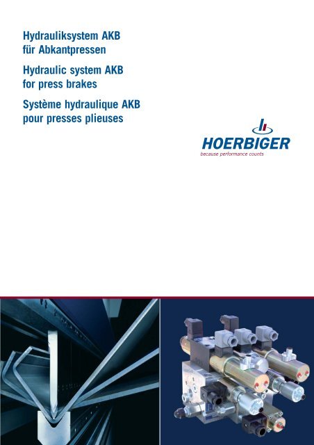
<strong>Hydrauliksystem</strong> <strong>AKB</strong><br />
<strong>für</strong> <strong>Abkantpressen</strong><br />
<strong>Hydraulic</strong> system <strong>AKB</strong><br />
for press brakes<br />
Système hydraulique <strong>AKB</strong><br />
pour presses plieuses
Pressensteuerung <strong>AKB</strong><br />
Inhalt Seite<br />
Allgemeines 2-3<br />
Basissystem 4<br />
Optionen 5<br />
Schaltplan 6<br />
Stückliste 7<br />
Funktionsdiagramm 8<br />
Kenngrößen 9<br />
Abmessungen 10-17<br />
Baumusterprüfbescheinigung 18<br />
Formular <strong>für</strong> Anfrage 19<br />
Allgemeines<br />
� Das HOERBIGER <strong>Hydrauliksystem</strong><br />
<strong>AKB</strong> wurde konzipiert <strong>für</strong> CNCgesteuerte<br />
<strong>Abkantpressen</strong>,<br />
vorzugsweise <strong>für</strong> Presskräfte bis ca.<br />
2.000 kN<br />
� Alle erforderlichen Ventile<br />
(außer Nachsaugventile) sind<br />
kompakt in einem Steuerblock<br />
zusammengefasst<br />
� Bei Einsatz des <strong>Hydrauliksystem</strong>s<br />
<strong>AKB</strong> sollte der horizontale<br />
Abstand zwischen den beiden<br />
Pressenzylindern maximal<br />
3.500 mm betragen<br />
� Es stehen zwei Varianten zur Auswahl:<br />
- mit integrierter Druckwaage, zur<br />
Steigerung der Energieeffiziens<br />
und damit verbundener<br />
Reduzierung der Ölerwärmung<br />
- ohne Druckwaage<br />
� Schnittstellen an den Modulen<br />
ermöglichen den Anbau folgender<br />
Optionen:<br />
- Modul <strong>für</strong> Werkzeugklemmung<br />
ohne Druckregelung<br />
- Modul <strong>für</strong> Werkzeugklemmung<br />
mit Druckregelung<br />
- Proportionalhydraulische<br />
Bombierung<br />
All rights, errors and changes reserved.<br />
© Copyright by HOERBIGER 2008<br />
A3H539X-08.2008<br />
<strong>Hydraulic</strong> press control <strong>AKB</strong><br />
Contents Page<br />
General 2-3<br />
Basic system 4<br />
Options 5<br />
Circuit diagram 6<br />
Parts list 7<br />
Operating sequence diagram 8<br />
Characteristics 9<br />
Dimensions 10-17<br />
Design test certificate 18<br />
Form for inquires 19<br />
General<br />
� The hydraulic system <strong>AKB</strong><br />
from HOERBIGER was designed<br />
for CNC-controlled press brakes,<br />
especially for pressing forces up<br />
to approx. 2,000 kN<br />
� All valves required (except the<br />
suction valves) are combined<br />
in one control block<br />
� If the hydraulic system <strong>AKB</strong> is<br />
used, the horizontal distance<br />
between the two pressing<br />
cylinders should be 3,500 mm<br />
maximum<br />
� Two variants are available:<br />
- with integrated Load-sensing<br />
module to increase the energy<br />
efficiency and thus reduce the<br />
heating of the oil<br />
- without Load-sensing module<br />
� The following optional devices can<br />
be connected to the interfaces of<br />
the modules:<br />
- Module for tool clamping without<br />
pressure regulator<br />
- Module for tool clamping with<br />
pressure regulator<br />
- Proportional hydraulic crowning<br />
2<br />
Commande de presse <strong>AKB</strong><br />
Sommaire Page<br />
Généralités 2-3<br />
Système de base 4<br />
Options 5<br />
Plan schématique 6<br />
Nomenclature 7<br />
Diagramme fonctionnel 8<br />
Caractéristiques 9<br />
Dimensions 10-17<br />
Certification 18<br />
Formulaire pour demande 19<br />
Généralités<br />
� Le système hydraulique <strong>AKB</strong><br />
de HOERBIGER a été conçu pour<br />
les presses plieuses à commande<br />
numérique de capacité maximale<br />
de 2.000 kN<br />
� Tous les distributeurs nécessaires<br />
(sauf les clapets d’aspiration) sont<br />
intégrés de manière dans un<br />
bloc de commande<br />
� Lorsque l’on utilise le système<br />
hydraulique <strong>AKB</strong>, il est souhaitable<br />
que l’intervalle entre les deux<br />
vérins de presse ne dépasse pas<br />
3.500 mm<br />
� Il existe deux variantes au choix :<br />
- avec balance de pression<br />
pour augmenter l’efficacité<br />
énergétique et réduire ainsi<br />
l’échauffement de l’huile<br />
- sans balance de pression<br />
� Les interfaces combinées aux<br />
modules permettent le montage<br />
des options suivantes:<br />
- Module pour le bridage des outils<br />
sans régulation de pression<br />
- Module pour le bridage des outils<br />
avec de la régulation de pression<br />
- Bombage hydraulique<br />
proportionnel
Pressensteuerung <strong>AKB</strong><br />
� In Verbindung mit einer CNC-<br />
Steuerung und einem Wegmeßsystem<br />
an der Maschine wird eine hohe<br />
Positioniergenauigkeit bei optimalem<br />
Synchronlauf erreicht<br />
� Das HOERBIGER <strong>Hydrauliksystem</strong><br />
S<strong>AKB</strong> entspricht den gültigen UVV-<br />
Richtlinien und ist mit Baumusterprüfbescheinigung<br />
Nr.: 98325<br />
zertifiziert<br />
(Voraussetzung <strong>für</strong> die Wirksamkeit<br />
des Zertifikates ist die Beachtung<br />
sämtlicher Installations- und<br />
Bedienungshinweise)<br />
� Weitere leistungsfähige HOERBIGER<br />
<strong>Hydrauliksystem</strong>e <strong>für</strong> <strong>Abkantpressen</strong><br />
stehen zur Verfügung:<br />
- System IPA<br />
- System AVB<br />
- System AMB<br />
- System PVM<br />
� Nützliche Hinweise zu allen<br />
Systemen sowie ein Berechnungsprogramm<br />
zur Dimensionierung<br />
von hydraulischen Systemen <strong>für</strong><br />
<strong>Abkantpressen</strong> finden sie auch<br />
im Internet unter: www.hoerbiger.com<br />
� Wichtiger Hinweis:<br />
- Die Umsetzung der den hydraulischen<br />
Pressensystemen beiliegenden<br />
Montageanleitung und insbesondere<br />
die Beachtung der dort beschriebenen<br />
Sicherheitshinweise ist in jedem<br />
Falle uneingeschränkt zu gewährleisten!<br />
All rights, errors and changes reserved.<br />
© Copyright by HOERBIGER 2008<br />
A3H539X-08.2008<br />
<strong>Hydraulic</strong> press control <strong>AKB</strong> Commande de presse <strong>AKB</strong><br />
Allgemeines General<br />
Généralités<br />
� A high positioning accuracy at an<br />
optimum synchronous running is<br />
achieved through the the combined<br />
use of the CNC-control and a<br />
displacement measuring system<br />
� The hydraulic system S<strong>AKB</strong> from<br />
HOERBIGER corresponds to the<br />
regulations for prevention of accidents<br />
in force and is certified with the<br />
design test certificate No. 98325<br />
(precondition for the validity of this<br />
certificate is that all installation<br />
and operating instructions have been<br />
observed)<br />
� The following efficient hydraulic<br />
systems for press brakes are<br />
available from HOERBIGER:<br />
- IPA system<br />
- AVB system<br />
- AMB system<br />
- PVM system<br />
� You will find further helpful<br />
information on all systems as well<br />
as a calculation program for the<br />
dimensioning of hydraulic systems<br />
for press brakes on our web site:<br />
www.hoerbiger.com<br />
� Important Note:<br />
- Pay attention to and realize the<br />
assembly instruction and their safety<br />
precautions and warning notes, which<br />
is attached to the hydraulic press<br />
brake systems!<br />
3<br />
� Grâce à une commande numérique<br />
et une règle de mesure de position<br />
sur la machine, on obtiendra une<br />
précision de positionnement pour un<br />
déplacement synchronisé optimum<br />
� Le système hydraulique HOERBIGER<br />
S<strong>AKB</strong> répond à la législation en<br />
vigueur concernant la prévention des<br />
accidents et est certifié n° 98325<br />
(La condition de validité du certificat<br />
étant le respect de toutes les<br />
précautions d’utilisation)<br />
� D’autres systèmes hydrauliques<br />
HOERBIGER performants pour<br />
presses plieuses sont disponibles:<br />
- Système IPA<br />
- Système AVB<br />
- Système AMB<br />
- Système PVM<br />
� Vous trouverez d’autres<br />
informations utiles ainsi qu’un<br />
programme de calcul de<br />
dimensionnement pour système<br />
hydraulique de presses plieuses<br />
sur notre site Web: www.hoerbiger.com<br />
� Remarques importantes:<br />
- Suivez les instructions de montage sur<br />
les systèmes de presse hydrauliques<br />
en tenant particulièrement compte des<br />
indications de sécurité!
<strong>AKB</strong> - Basissystem / Kombination der Module<br />
<strong>AKB</strong> - Basic system / Combibation of the modules<br />
<strong>AKB</strong> - Système de base / Combinaison des modules<br />
Kompaktblock<br />
Compact block<br />
Bloc compact<br />
Die Ventile <strong>für</strong> Regelung, Hochhaltung<br />
und proportionale Druckeinstellung<br />
sowie die Ansteuerung der Nachsaugventile<br />
sind kompakt in einem Steuerblock<br />
zusammengefaßt.<br />
Die Nachsaugventile sind am Zylinderboden<br />
angeordnet.<br />
Dieses System ist wahlweise mit oder<br />
ohne Load-sensing-Regelung lieferbar.<br />
The valves for control, high retaining<br />
and proportional pressure control, as<br />
well as the control for the suction alves<br />
are all combined into one compact<br />
central valve manifold.<br />
The suction valves are placed at the<br />
bottom of the cylinder.<br />
This system may be delivered with or<br />
without the optional load sensing<br />
regulator.<br />
Les distributeurs pour le positionnement,<br />
le maintien, le réglage proportionnel de<br />
la pression, ainsi que le pilotage des<br />
clapets de gavage sont réunis de<br />
manière compacte sur un bloc de<br />
commande.<br />
Les clapets de gavage sont disposés en<br />
pied de vérin. Ce système peut être<br />
fourni avec ou sans régulation loadsensing.<br />
Type Qmax<br />
(l/min)<br />
S<strong>AKB</strong> 53605I06_ 50<br />
mit Druckwaage<br />
with Load-sensing module<br />
avec balance de pression<br />
S<strong>AKB</strong> 53839I06_ 50<br />
ohne Druckwaage<br />
without Load-sensing module<br />
sans balance de pression<br />
All rights, errors and changes reserved.<br />
© Copyright by HOERBIGER 2008<br />
A3H539X-08.2008<br />
Nachsaugventil mit Gehäuse<br />
Suction valve with housing<br />
Clapet de gavage avec corps<br />
Diese sind <strong>für</strong> den Aufbau auf den<br />
Zylinder vorgesehen.<br />
HOERBIGER Nachsaugventile<br />
sind grundsätzlich in der Grundstellung<br />
geöffnet und werden zum Füllen und<br />
Entleeren der Presszylinder beim<br />
Schließen und Öffnen im Eilgang<br />
verwendet. Die Ansteuerung erfolgt<br />
über ein 4/2-Wege-Schieberventil<br />
(Bestandteil des Kompaktblocks).<br />
These are provided to be flanged on<br />
the cylinder.<br />
On principle, the suction valves from<br />
HOERBIGER are opened in the initial<br />
position and are used to fill and<br />
discharge the pressing cylinders<br />
during closing and opening in rapid<br />
movement.<br />
They are controlled via a 4/2- way<br />
spoole valve (integral part of the<br />
compact block).<br />
Ceux-ci sont prévus pour être<br />
montés sur le cylindre.<br />
Les clapets de gavage HOERBIGER<br />
sont toujours ouverts en position<br />
initiale et seront utilisés pour emplir<br />
et vider le cylindre de la presse lors<br />
de l’ouverture et de la fermeture en<br />
vitesse rapide. Les commandes sont<br />
effectuées par un distributeur 4/2 à<br />
tiroir (composant du bloc compact).<br />
Type Type<br />
HB90638-002<br />
(NG 32)<br />
HB90639-002<br />
(NG 50)<br />
2 Stück pro Maschine erforderlich<br />
2 pieces necessary per machine<br />
2 pièces nécessaires par machine<br />
4<br />
Nachsaugventil ohne Gehäuse<br />
Suction valve without housing<br />
Clapet de gavage sans corps<br />
Diese sind <strong>für</strong> den Einbau in den<br />
Zylinder vorgesehen.<br />
HOERBIGER Nachsaugventile<br />
sind grundsätzlich in der Grundstellung<br />
geöffnet und werden zum Füllen und<br />
Entleeren der Presszylinder beim<br />
Schließen und Öffnen im Eilgang<br />
verwendet. Die Ansteuerung erfolgt<br />
über ein 4/2-Wege-Schieberventil<br />
(Bestandteil des Kompaktblocks).<br />
These are provided to be installed<br />
inside the cylinder.<br />
On principle, the suction valves from<br />
HOERBIGER are opened in the initial<br />
position and are used to fill and<br />
discharge the pressing cylinders<br />
during closing and opening in rapid<br />
movement.<br />
They are controlled via a 4/2- way<br />
spoole valve (integral part of the<br />
compact block).<br />
Ceux-ci sont prévus pour être montés<br />
dans le cylindre.<br />
Les clapets de gavage HOERBIGER<br />
sont toujours ouverts en position<br />
initiale et seront utilisés pour emplir<br />
et vider le cylindre de la presse lors<br />
de l’ouverture et de la fermeture en<br />
vitesse rapide. Les commandes sont<br />
effectuées par un distributeur 4/2 à<br />
tiroir (composant du bloc compact).<br />
HB99753-002<br />
(NG 32)<br />
HV07902<br />
(NG 50)<br />
2 Stück pro Maschine erforderlich<br />
2 pieces necessary per machine<br />
2 pièces nécessaires par machine
<strong>AKB</strong>- Optionen <strong>für</strong> Kompaktblock<br />
<strong>AKB</strong>- Options for compact block<br />
<strong>AKB</strong> - Options pour bloc compact<br />
HB51191-002<br />
HB53480-002<br />
HB53479-002<br />
All rights, errors and changes reserved.<br />
© Copyright by HOERBIGER 2008<br />
A3H539X-08.2008 5<br />
Option „A“<br />
Proportionalhydraulische Bombierung<br />
Proportional hydraulic crowning<br />
Bombage hydraulique proportionnel<br />
Option „B“<br />
Modul <strong>für</strong> Werkzeugklemmung mit Druckregelung<br />
Module for tool clamping with pressure regulator<br />
Module pour le bridage des outils avec régulation de pression<br />
Option „C“<br />
Modul <strong>für</strong> Werkzeugklemmung ohne Druckregelung<br />
Module for tool clamping without pressure regulator<br />
Module pour le bridage des outils sans régulation de pression
Pressensteuerung <strong>AKB</strong><br />
mit Optionen<br />
Schaltplan Circuit diagram<br />
Plan schématique<br />
Nachsaugventil<br />
Suction valve<br />
Clapet de gavage<br />
All rights, errors and changes reserved.<br />
© Copyright by HOERBIGER 2008<br />
A3H539X-08.2008<br />
Kompaktblock mit integrierter Druckwaage<br />
Compact block with integrated Load-sensing module<br />
Bloc compact avec la balance de pression integrée<br />
Nachsaugventil<br />
Suction valve<br />
Clapet de gavage<br />
Kompaktblock ohne integrierte Druckwaage<br />
Compact block without integrated Load-sensing module<br />
Bloc compact sans la balance de pression integrée<br />
<strong>Hydraulic</strong> press control <strong>AKB</strong><br />
with options<br />
6<br />
Commande de presse <strong>AKB</strong><br />
avec options<br />
Nachsaugventil<br />
Suction valve<br />
Clapet de gavage<br />
Nachsaugventil<br />
Suction valve<br />
Clapet de gavage<br />
Anschluss Optionen<br />
Connection options<br />
Raccordement options<br />
Anschluss Optionen<br />
Connection options<br />
Raccordement options
Pressensteuerung <strong>AKB</strong> <strong>Hydraulic</strong> press control <strong>AKB</strong> Commande de presse <strong>AKB</strong><br />
Schaltplan Optionen Circuit diagram options<br />
Plan schématique options<br />
Stückliste Parts list<br />
Nomenclature<br />
S<strong>AKB</strong> - Kompaktblock / compact block / bloc compact<br />
Nr. Bezeichnung/Description/Désignation Type<br />
0.0360 Wechselventil<br />
0.0500 Shuttle valve<br />
0.0550 Valve de sélection<br />
0.0320 Düse / Orifice / Gicleur<br />
0.0340, 0.0610, 0.0710, 0.0910, 0.0970<br />
0.0200 Proportional-Druckventil<br />
Pressure control valve<br />
VPDBVE16E_<br />
0.0300<br />
Limiteur de pression proportionnel<br />
Druckwaage<br />
Load-sensing module<br />
Balance de pression<br />
0.0840 4/2-Wege Schieberventil<br />
4/2 way spool valve<br />
Distributeur 4/2 à tiroir<br />
SBM220PC06_<br />
0.0420 Rückschlagventil<br />
0.0440 Check valve<br />
0.0940 Clapet anti-retour<br />
0.0960, 0.0980<br />
0.0400 Druckbegrenzungsventil VDBE03EE<br />
0.0600 Pressure relief valve VDBE03E_<br />
0.0700 Limiteur de pression VDBE03E_<br />
0.0650 2/2-Wege-Sitzventil IVN221BE08_<br />
0.0750 2/2 way poppet valve<br />
0.0800<br />
Distributeur à clapet 2/2<br />
Proportional-Wegeventil PIL400PC06_<br />
0.0820 Proportional way valve<br />
Distributeur proportionnel<br />
Option A - Proportionalhydraulische Bombierung / Proportional<br />
hydraulic crowning / Bombage hydraulique proportionnel<br />
Nr. Bezeichnung/Description/Désignation Type<br />
6.0200 Proportional-Druckregelventil VPDM3PC_<br />
Proportional pressure control valve<br />
Régulateur de pression à action proportionnelle<br />
All rights, errors and changes reserved.<br />
© Copyright by HOERBIGER 2008<br />
A3H539X-08.2008<br />
6.0000<br />
6.0200<br />
6.Y12<br />
A optional<br />
optionally<br />
au choix<br />
5.0700<br />
5.0000<br />
5.0600<br />
5.0200 5.0300<br />
5.0400<br />
5.Y11 5.Y10<br />
B optional<br />
optionally<br />
au choix<br />
7<br />
5.0800<br />
4.0700<br />
4.0200 4.0300<br />
4.0400<br />
4.Y11 4.Y10 4.0500<br />
4.0000<br />
4.0600<br />
C optional<br />
optionally<br />
au choix<br />
Option B - Modul <strong>für</strong> Werkzeugklemmung mit Druckregelung /<br />
Module for tool clamping with pressure regulator /<br />
Module pour le bridage des outils avec régulation de pression<br />
Nr. Bezeichnung/Description/Désignation Type<br />
5.0200 2/2-Wege-Sitzventil SVN221BE08_<br />
5.0300 2/2 way poppet valve<br />
5.0400<br />
Distributeur à clapet 2/2<br />
Rückschlagventil<br />
Check valve<br />
Clapet anti-retour<br />
RVB_<br />
5.0600 Düse<br />
Orifice<br />
Gicleur<br />
5.0700 Druckschalter<br />
Pressure switch<br />
Pressostat<br />
5.0800 Druckregelventil<br />
Pressure control valve<br />
Réducteur de pression<br />
Option C - Modul <strong>für</strong> Werkzeugklemmung ohne Druckregelung /<br />
Module for tool clamping without pressure regulator /<br />
Module pour le bridage des outils sans régulation de pression<br />
Nr. Bezeichnung/Description/Désignation Type<br />
4.0200 2/2-Wege-Sitzventil SVN221BE08_<br />
4.0300 2/2 way poppet valve<br />
4.0400<br />
Distributeur à clapet 2/2<br />
Rückschlagventil<br />
Check valve<br />
Clapet anti-retour<br />
RVB_<br />
4.0500 Düse<br />
4.0600 Orifice<br />
Gicleur<br />
4.0700 Druckschalter<br />
Pressure switch<br />
Pressostat
Pressensteuerung <strong>AKB</strong><br />
Funktionsdiagramm Operating sequence diagram Diagramme fonctionnel<br />
* Wert 1 bei 0.Y01, 0.Y04/0.Y06 und 0.Y05/0.Y07 ist maschinen- und regelzustandsabhängig<br />
* Value 1 of 0.Y01, 0.Y04/0.Y06 and 0.Y05/0.Y07 depends on machine type<br />
* Valeur 1 par 0.Y01, 0.Y04/0.Y06 et 0.Y05/0.Y07 dépendant de la machine et du réglage<br />
Positionsanzeige, 4/2-Wege-Schieberventil<br />
Position indicator, 4/2-way directional<br />
control valve<br />
Indicateur de position, Distributeur<br />
4/2 à tiroir<br />
0.S08<br />
1<br />
0<br />
All rights, errors and changes reserved.<br />
© Copyright by HOERBIGER 2008<br />
A3H539X-08.2008<br />
Positionsanzeige, Wege-Sitzventil,<br />
vorgesteuert<br />
Position indicator, Poppet valve, pilot<br />
operated<br />
Indicateur de position, Distributeur à<br />
clapet, pilotage<br />
Positionsanzeige, Proportional -<br />
4/3-Wegeventil<br />
Position indicator, Proportional<br />
4/3-way valve<br />
Indicateur de position, Distributeur<br />
4/3-proportionnel<br />
0.S04 / 0.S06<br />
1<br />
0<br />
0.S02 / 0.S03<br />
1<br />
0<br />
<strong>Hydraulic</strong> press control <strong>AKB</strong> Commande de presse <strong>AKB</strong><br />
Pos. 0.0650 / 0.0750<br />
Wege-Sitzventil, vorgesteuert<br />
Poppet valve, pilot operated<br />
Distributeur à clapet, pilotage<br />
0.Y02 / 0.Y03<br />
1<br />
0<br />
Pos. 0.0840<br />
4/2-Wege-Schieberventil<br />
4/2-way directional control valve<br />
Distributeur 4/2 à tiroir<br />
8<br />
0.Y08<br />
1<br />
0<br />
Pos. 0.0800 / 0.0820<br />
Proportional - 4/3-Wegeventil<br />
Proportional 4/3-way valve<br />
Distributeur 4/3-proportionnel<br />
0.Y05 / 0.Y07<br />
0.Y04 / 0.Y06<br />
1*<br />
0<br />
1*<br />
Pos. 0.0200<br />
Proportional-Druckbegrenzungsventil<br />
Proportional pressure relief valve<br />
Limiteur de pression proportionnel<br />
0.Y01<br />
1*<br />
0<br />
U T<br />
Y - Achse<br />
Y - Axis<br />
Y - Axe<br />
O T<br />
Bezeichnung<br />
Designation<br />
Désignation<br />
Stellorgan<br />
Positioning<br />
device<br />
Transmetteur<br />
de position<br />
Zustand<br />
Condition<br />
Condition<br />
Zeit Time Période<br />
Eilgang ab Mutepunkt Arbeitsgang Haltezeit Dekompression Eilgang retour<br />
Rapid speed down Mutepoint Sequence of Holding time Decompression Rapid speed<br />
O T Approche rapide Point de passage operations Temps de Decompression return<br />
O T<br />
GV/PV Phase de travail maintien<br />
Retour rapide
Kenngrößen<br />
Allgemeines General<br />
Généralités<br />
Einbaulage<br />
beliebig<br />
Achtung:<br />
Proportional-Wegeventil (Pos. 0.0800 /<br />
0.0820) immer waagerecht<br />
Masse<br />
S<strong>AKB</strong>53605I06_: 16,7 kg<br />
S<strong>AKB</strong>53839I06_: 16,0 kg<br />
HB99753-002 (NG32): 1,1 kg<br />
HB90638-002 (NG32): 2,5 kg<br />
HV03844 (NG50): 3,7 kg<br />
HB90639-002 (NG50): 7,4 kg<br />
Option A: 2,5 kg<br />
Option B: 4,9 kg<br />
Option C: 4,0 kg<br />
Umgebungstemperaturbereich<br />
min -10 °C, max +50 °C<br />
Korrosionsschutz<br />
Oberfläche geschützt durch<br />
Korrosions-Schutzöl<br />
Hydraulische Kenngrößen<br />
Betriebsdruck (Eingangsdruck)<br />
max. = 280 bar<br />
Druckflüssigkeit<br />
Mineralöl nach DIN51524,<br />
andere Medien auf Anfrage<br />
Druckflüssigkeitstemperaturbereich<br />
min = -10 °C, max = +70 °C<br />
Volumenstrom<br />
max. = 50 l/min<br />
Viskositätsbereich<br />
min = 10 mm 2 /s, max = 600 mm 2 /s,<br />
empfohlener Bereich <strong>für</strong> Dauerbetrieb:<br />
20 mm 2 /s bis 100 mm 2 /s<br />
Verschmutzungsklasse <strong>für</strong><br />
Druckmittel<br />
max. Klasse 19/16/13 nach<br />
ISO4406:1999<br />
All rights, errors and changes reserved.<br />
© Copyright by HOERBIGER 2008<br />
A3H539X-08.2008<br />
Characteristics<br />
Installation<br />
arbitrary<br />
Attention:<br />
Proportional way valve (Pos.0.0800 /<br />
0.0820) always horizontally<br />
Weight (mass)<br />
S<strong>AKB</strong>53605I06_: 16,7 kg<br />
S<strong>AKB</strong>53839I06_: 16,0 kg<br />
HB99753-002 (NG32): 1,1 kg<br />
HB90638-002 (NG32): 2,5 kg<br />
HV03844 (NG50): 3,7 kg<br />
HB90639-002 (NG50): 7,4 kg<br />
Option A: 2,5 kg<br />
Option B: 4,9 kg<br />
Option C: 4,0 kg<br />
Ambient temperature range<br />
min -10 °C, max +50 °C<br />
Rust protection<br />
Surface protected by protective oil<br />
<strong>Hydraulic</strong> characteristics<br />
Operating pressure (supply pressure)<br />
max. = 280 bar<br />
<strong>Hydraulic</strong> medium<br />
Mineral oil according to DIN51524,<br />
other media on request<br />
Pressure media temperature range<br />
min = -10 °C, max = +70 °C<br />
Volume flow<br />
max. = 50 l/min<br />
Viscosity range<br />
min = 10 mm 2 /s, max = 600 mm 2 /s,<br />
recommended range for continuous<br />
operation: 20 mm 2 /s bis 100 mm 2 /s<br />
Contamination level for pressure<br />
medium<br />
max. class 19/16/13 according to<br />
ISO4406:1999<br />
9<br />
Caractéristiques<br />
Position de montage<br />
indifférente<br />
Attention:<br />
Distributeur proportionnel (Pos.0.0800 /<br />
0.0820) doit être toujours horizontal<br />
Masse<br />
S<strong>AKB</strong>53605I06_: 16,7 kg<br />
S<strong>AKB</strong>53839I06_: 16,0 kg<br />
HB99753-002 (NG32): 1,1 kg<br />
HB90638-002 (NG32): 2,5 kg<br />
HV03844 (NG50): 3,7 kg<br />
HB90639-002 (NG50): 7,4 kg<br />
Option A: 2,5 kg<br />
Option B: 4,9 kg<br />
Option C: 4,0 kg<br />
Plage de température ambiante<br />
min -10 °C, max +50 °C<br />
Protection contre la corrosion<br />
Surface traitée anti-corrosion par<br />
protection à l’huile<br />
Caractéristiques hydrauliques<br />
Pression de service (pression d’entrée)<br />
max. = 280 bar<br />
Fluide hydraulique<br />
Huile minérale DIN51524,<br />
autres sur demande<br />
Plage de température du fluide<br />
hydraulique<br />
min = -10 °C, max = +70 °C<br />
Débit<br />
max. = 50 l/min<br />
Plage de viscosité<br />
min = 10 mm 2 /s, max = 600 mm 2 /s,<br />
plage recommandée pour<br />
fonctionnement continu: 20 mm 2 /s bis<br />
100 mm 2 /s<br />
Degré de pollution<br />
max. classe 19/16/13 suivant<br />
ISO4406:1999 admissible
Ausführung Kompaktblock mit<br />
integrierter Druckwaage<br />
All rights, errors and changes reserved.<br />
© Copyright by HOERBIGER 2008<br />
A3H539X-08.2008<br />
Design compact block with<br />
Load-sensing module<br />
Abmessungen Dimensions<br />
Dimensions<br />
0.0600<br />
0.0200 0.0800 0.0300<br />
0.0650 0.0820 0.0750<br />
0.0700 0.0400 0.0840<br />
Anschluss Größe Anzugsmoment<br />
Connection Size Torque<br />
Raccord Taille Couple<br />
T4 G3/4 155Nm<br />
P, A1, A2, B1, B2, T1, T2, T3, T5 G1/2 90Nm<br />
T, T6, F, L G3/8 55Nm<br />
M1, M2, M3, M4, M5 G1/4 33Nm<br />
10<br />
2x Ø8,5<br />
73<br />
62<br />
226<br />
220<br />
240<br />
T6<br />
B2<br />
A2<br />
T2<br />
190<br />
17<br />
178<br />
T5<br />
59,2 105<br />
Modèle bloc compact avec la<br />
balance de pression<br />
164,5<br />
150<br />
140<br />
F<br />
140<br />
128<br />
117,5<br />
M2 P<br />
55<br />
78<br />
43<br />
30<br />
T3 T1 T4<br />
M5 M4<br />
M3<br />
303,9<br />
90<br />
B1<br />
A1<br />
0<br />
L<br />
0 9<br />
0<br />
61<br />
0<br />
17<br />
33<br />
67,5<br />
80<br />
85<br />
85<br />
80<br />
58<br />
22<br />
0
Ausführung Kompaktblock mit<br />
integrierter Druckwaage<br />
Darstellung mit Optionen Representation with options<br />
Représentation avec options<br />
6.0200<br />
Option „A“<br />
4.0300<br />
53<br />
4.0200<br />
4.0700<br />
Option „C“<br />
Design compact block with<br />
Load-sensing module<br />
5.0800<br />
5.0300<br />
5.0200<br />
5.0700<br />
Option „B“<br />
53 53<br />
All rights, errors and changes reserved.<br />
© Copyright by HOERBIGER 2008<br />
A3H539X-08.2008 11<br />
Modèle bloc compact avec la<br />
balance de pression
Ausführung Kompaktblock<br />
ohne Druckwaage<br />
All rights, errors and changes reserved.<br />
© Copyright by HOERBIGER 2008<br />
A3H539X-08.2008<br />
F<br />
Design compact block<br />
without Load-sensing<br />
Abmessungen Dimensions<br />
Dimensions<br />
0.0600 0.0800 0.0200 0.0650 0.0820 0.0750<br />
0.0700 0.0840<br />
Anschluss Größe Anzugsmoment<br />
Connection Size Torque<br />
Raccord Taille Couple<br />
T1, T2 G3/4 155Nm<br />
P, A1, A2, B1, B2, T3 G1/2 90Nm<br />
F, L G3/8 55Nm<br />
M1, M2, M3, G1/4 33Nm<br />
12<br />
2x Ø8,5<br />
45<br />
0<br />
185<br />
173<br />
185<br />
0<br />
T2<br />
121<br />
111<br />
T1<br />
89<br />
T3<br />
L<br />
64<br />
B2 F B1<br />
M2<br />
A2 A1<br />
142<br />
138<br />
P<br />
40<br />
77 105<br />
Modèle bloc compact sans la<br />
balance de pression<br />
92,5<br />
88<br />
318,1<br />
44<br />
12<br />
0<br />
0<br />
115,1<br />
0<br />
9<br />
17<br />
62<br />
84<br />
96<br />
105<br />
95<br />
86<br />
83<br />
23<br />
0
Ausführung Kompaktblock<br />
ohne Druckwaage<br />
Darstellung mit Optionen Representation with options Représentation avec options<br />
6.0200<br />
Option „A“<br />
4.0300<br />
All rights, errors and changes reserved.<br />
© Copyright by HOERBIGER 2008<br />
A3H539X-08.2008<br />
53<br />
4.0200<br />
4.0700<br />
Option „C“<br />
5.0800<br />
Design compact block without<br />
Load-sensing module<br />
5.0300<br />
5.0700<br />
5.0200<br />
Option „B“<br />
53 53<br />
13<br />
Modèle bloc compact sans la<br />
balance de pression
Abmessungen<br />
Nachsaugventil NG32<br />
Dimensions suction<br />
valve NG32<br />
Zylindereinbau Cylinder installation<br />
Installation de vérin<br />
T<br />
P<br />
60<br />
Mindestschraubenlänge <strong>für</strong> Befestigung:<br />
50 mm. Wir empfehlen Schrauben<br />
der Festigkeitsklasse 10.9<br />
(34 +2 Nm), andere auf Anfrage.<br />
F<br />
Steueranschluss „F“<br />
Control port „F“<br />
Raccord de commande „F“<br />
Minimum screw length for fixing: 50<br />
mm. We recommend screws of the<br />
property class 10.9 (34 +2 Nm),<br />
others on request.<br />
All rights, errors and changes reserved.<br />
© Copyright by HOERBIGER 2008<br />
A3H539X-08.2008 14<br />
13<br />
G¼<br />
Druckanschluss „P“<br />
Pressure port „P“<br />
Raccord de pression „P“<br />
35<br />
Tankanschluss „T“<br />
Tank connection „T“<br />
Raccord de réservoir „T“<br />
60<br />
44,5 ±0,2<br />
50,8 +0,05<br />
22,25 ±0,1<br />
2<br />
22,25 ±0,1<br />
Druckanschluß „P“<br />
Pressure port „P“<br />
Raccord de pression „P“<br />
0,8<br />
Dimensions clapet de<br />
gavage NG32<br />
Anschlußmaße <strong>für</strong> Deckel<br />
Connection dimensions for the cover<br />
Logement du couvercle<br />
60<br />
44,5 ±0,2<br />
Einbauraum<br />
Mounting space<br />
Logement<br />
0,8<br />
20°0,4<br />
0,8<br />
+0,2<br />
ø38,1H8<br />
ø25<br />
0,8<br />
0,4<br />
M8x17<br />
(min.)<br />
0,05<br />
ø33<br />
29 +0,5<br />
Tankanschluss „T“<br />
Tank connection „T“<br />
Raccord de réservoir „T“<br />
Longueur de vis minimum pour<br />
fixation: 50 mm. Nous recommandons<br />
d’utiliser des vis de classe de résistance<br />
10.9 (34 +2 Nm), autres sur demande.
Abmessungen<br />
Nachsaugventil NG32<br />
SAE 1¼"<br />
3000 psi<br />
P<br />
45<br />
Zylinderaufbau Flanged on the cylinder<br />
Installation sur le vérin<br />
58,72<br />
30<br />
12<br />
G¼<br />
All rights, errors and changes reserved.<br />
© Copyright by HOERBIGER 2008<br />
A3H539X-08.2008<br />
42<br />
F<br />
30,18<br />
ø36<br />
Mindestschraubenlänge <strong>für</strong> Befestigung:<br />
100 mm. Wir empfehlen<br />
Schrauben der Festigkeitsklasse 10.9<br />
(68 +2 Nm), andere auf Anfrage.<br />
80<br />
~120<br />
Dimensions suction<br />
valve NG32<br />
M10<br />
(4x)<br />
Steueranschluss „F“<br />
Control port „F“<br />
Raccord de commande „F“<br />
T<br />
P<br />
Tankanschluss „T“<br />
Tank connection „T“<br />
Raccord de réservoir „T“<br />
F<br />
Minimum screw length for fixing:<br />
100 mm. We recommend screws of the<br />
property class 10.9 (68 +2 Nm), others<br />
on request.<br />
15<br />
ø24<br />
M10<br />
(4x)<br />
25<br />
25<br />
Dimensions clapet de<br />
gavage NG32<br />
Druckanschluss „P“<br />
Pressure port „P“<br />
Raccord de pression „P“<br />
89<br />
Anschlußmaße <strong>für</strong> Block<br />
Connection dimensions for the block<br />
Logement pour le bloc hydraulique<br />
14 14<br />
P<br />
89<br />
37 37<br />
45<br />
90<br />
Longueur de vis minimum pour fixation:<br />
100 mm. Nous recommandons<br />
d’utiliser des vis de classe de résistance<br />
10.9 (68 +2 Nm), autres sur demande.
Abmessungen<br />
Nachsaugventil NG50<br />
Dimensions suction<br />
valve NG50<br />
Zylindereinbau Cylinder installation<br />
Installation de vérin<br />
80 +0,05<br />
83<br />
2<br />
0,8<br />
20°<br />
ø62<br />
Mindestschraubenlänge <strong>für</strong> Befestigung:<br />
60 mm. Wir empfehlen Schrauben<br />
der Festigkeitsklasse 10.9 (68 +2<br />
Nm), andere auf Anfrage.<br />
Minimum screw length for fixing: 60<br />
mm. We recommend screws of the<br />
property class 10.9 (68 +2 Nm), others<br />
on request.<br />
All rights, errors and changes reserved.<br />
© Copyright by HOERBIGER 2008<br />
A3H539X-08.2008 16<br />
40<br />
Steueranschluss „F“<br />
Control port „F“<br />
Raccord de commande „F“<br />
0,8<br />
Einbauraum<br />
Mounting space<br />
Logement<br />
+0,2<br />
ø62H8<br />
ø42<br />
0,8<br />
0,8<br />
0,4<br />
163<br />
0,4<br />
17<br />
0,05<br />
ø50<br />
G1/4<br />
48 +0,5<br />
Tankanschluss „T“<br />
Tank connection „T“<br />
Raccord de réservoir „T“<br />
Druckanschluß „P“<br />
Pressure port „P“<br />
Raccord de pression „P“<br />
Dimensions clapet de<br />
gavage NG50<br />
Druckanschluss „P“<br />
Pressure port „P“<br />
Raccord de pression „P“<br />
100<br />
41<br />
Tankanschluss „T“<br />
Tank connection „T“<br />
Raccord de réservoir „T“<br />
Anschlußmaße <strong>für</strong> Deckel<br />
Connection dimensions for the cover<br />
Logement du couvercle<br />
92<br />
80<br />
22,5°<br />
Longueur de vis minimum pour fixation:<br />
60 mm. Nous recommandons d’utiliser<br />
des vis de classe de résistance 10.9<br />
(68 +2 Nm), autres sur demande.<br />
T<br />
P<br />
8x45°(=360°)<br />
45°<br />
F<br />
ø6<br />
F<br />
F<br />
M10x22
Abmessungen<br />
Nachsaugventil NG50<br />
55<br />
45x52x1,9<br />
Zylinderaufbau Flanged on the cylinder<br />
Installation sur le vérin<br />
Steueranschluss „F“<br />
Control port „F“<br />
Raccord de commande „F“<br />
17<br />
G3/8<br />
F<br />
55<br />
T<br />
P<br />
P<br />
Mindestschraubenlänge <strong>für</strong> Befestigung:<br />
120 mm. Wir empfehlen Schrauben der<br />
Festigkeitsklasse 10.9 (110 +2 Nm),<br />
andere auf Anfrage.<br />
All rights, errors and changes reserved.<br />
© Copyright by HOERBIGER 2008<br />
A3H539X-08.2008<br />
F<br />
135<br />
F<br />
Dimensions suction<br />
valve NG50<br />
110<br />
Druckanschluss „P“<br />
Pressure port „P“<br />
Raccord de pression „P“<br />
P<br />
SAE 2"<br />
3000 psi<br />
55<br />
42,88<br />
Minimum screw length for fixing:<br />
120 mm. We recommend screws of the<br />
property class 10.9 (110 +2 Nm), others<br />
on request.<br />
59<br />
96<br />
77,77<br />
Tankanschluss „T“<br />
Tank connection „T“<br />
Raccord de réservoir „T“<br />
M12x26<br />
(min.)<br />
17<br />
Dimensions clapet de<br />
gavage NG50<br />
~195<br />
Steueranschluss „F“<br />
Control port „F“<br />
Raccord de commande „F“<br />
Anschlußmaße <strong>für</strong> Block<br />
Connection dimensions for the block<br />
Logement pour le bloc hydraulique<br />
135<br />
55<br />
43 43<br />
ø42<br />
P<br />
43<br />
43<br />
55<br />
110<br />
Longueur de vis minimum pour fixation:<br />
120 mm. Nous recommandons<br />
d’utiliser des vis de classe de résistance<br />
10.9 (110 +2 Nm), autres sur demande.
All rights, errors and changes reserved.<br />
© Copyright by HOERBIGER 2008<br />
A3H539X-08.2008 18
Anfrageformular - System <strong>AKB</strong> / Form for inquires - system <strong>AKB</strong> / Formulaire pour demande - système <strong>AKB</strong><br />
An: / To: / A : Von: / From: / Entre:<br />
HOERBIGER Firma/ Company/ Compagnie:<br />
Automatisierungstechnik GmbH Anschrift/ Address/ Adresse:<br />
Fax-Nr.: +49(0)8861 221-1265 Ansprechpartner/ Partner/ Interlocuteur:<br />
Tel.:<br />
Fax:<br />
email:<br />
Ich wünsche einen Vorschlag / Angebot eines <strong>AKB</strong> - Systems <strong>für</strong> folgende Maschine:<br />
I’d like a suggestion / supply of an <strong>AKB</strong> - system for the following machine:<br />
Je souhaite une proposition / offre pour un système <strong>AKB</strong> pour la machine suivante:<br />
Presskraft / Pressing force / Effort de pression kN<br />
Kolbendurchmesser Presszylinder / Piston diameter<br />
of the pressing cylinder / Diamètre d’ alésage vérin mm<br />
Stangendurchmesser Presszylinder /Piston rod diameter<br />
of the pressing cylinder / Diamètre de latige vérin mm<br />
Eil-Ab-Geschwindigkeit / Rapid speed down /<br />
Approche rapide mm/s<br />
Arbeitsgeschwindigkeit / Working speed /<br />
Vitesse de travail mm/s<br />
Eil-Auf-Geschwindigkeit / Rapid speed return /<br />
Retour rapide mm/s<br />
Balkengewicht inclusive Werkzeuge / Beam weight<br />
inclusive tools / Poids du tablier supérieur outillage compris kg<br />
Ventile stellungsüberwacht (Sicherheit) / monitoring of the ja / yes / oui<br />
valves (safety) / Surveillance des valves (sécurité) nein / no / non<br />
Optionen / Options / Options<br />
Oberwerkzeugklemmung / ja / yes / oui<br />
Upper tool clamping nein / no / non<br />
Bridage outils supérieurs Druck / pressure / pression<br />
Unterwerkzeugklemmung ja / yes / oui<br />
Lower tool clamping nein / no / non<br />
Bridage outils inférieurs Druck / pressure / pression<br />
Proportionalhydraulische Bombierung ja / yes / oui<br />
Proportional hydraulic crowning nein / no / non<br />
Bombage hydraulique proportionnel max. Druck / max. pressure / pression max.<br />
Druckwaage ja / yes / oui<br />
Load-sensing module nein / no / non<br />
Balance de pression<br />
Verwendete CNC-Steuerung / Fabrikat/ Make/ Produit:<br />
Used CNC-control / CN utilisées<br />
Type / Model / Modèle:<br />
Bedarf / Demand / Demande Systeme / Jahr, Systems / year, Système q/ Année<br />
All rights, errors and changes reserved.<br />
© Copyright by HOERBIGER 2008<br />
A3H539X-08.2008 19
HOERBIGER -<br />
the technology group<br />
Wherever we operate, we set standards with performance-defining components, system solutions, and services -<br />
and thereby increase the efficiency of the capital investment in premium capital goods.<br />
HOERBIGER Automation Technology<br />
is a business unit of HOERBIGER<br />
Holding AG, Zug / Switzerland.<br />
HOERBIGER is active throughout the<br />
world as a leading player in the fields<br />
of compression technology, automation<br />
technology and drive technology.<br />
In 2009, its 6,500 employees<br />
achieved sales of 772 million Euro.<br />
The focal points of its business<br />
activities include key components and<br />
services for compressors, gas engines<br />
HOERBIGER AUTOMATISIERUNGSTECHNIK GmbH<br />
Südliche Römerstraße 15<br />
86972 Altenstadt, Deutschland<br />
Phone:+49 (0)8861 221-0<br />
Fax: +49 (0)8861 221-13 05<br />
E-Mail: info-haut@hoerbiger.com<br />
www.hoerbiger.com<br />
A3H539X-08.2010<br />
and turbomachines,<br />
hydraulic systems and<br />
piezo technology for<br />
vehicles and machine tools,<br />
as well as components and<br />
systems for shift and clutch<br />
operations in vehicle drive trains<br />
of all kinds. Through innovations in<br />
attractive technological niche markets,<br />
the HOERBIGER Group sets standards<br />
and delivers cutting-edge solutions for<br />
the benefit of its customers.