Scarica il manuale - Mosa
Scarica il manuale - Mosa
Scarica il manuale - Mosa

Create successful ePaper yourself
Turn your PDF publications into a flip-book with our unique Google optimized e-Paper software.
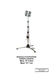
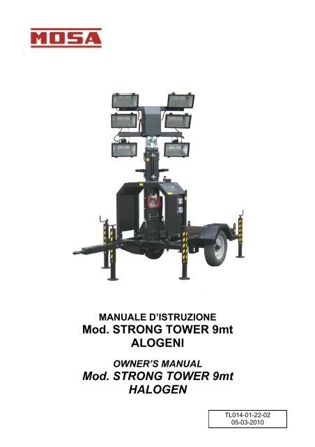
MANUALE D’ISTRUZIONE<br />
Mod. STRONG TOWER 9mt<br />
ALOGENI<br />
OWNER’S MANUAL<br />
Mod. STRONG TOWER 9mt<br />
HALOGEN<br />
TL014-01-22-02<br />
05-03-2010
STRONG TOWER 9 mt HALOGEN<br />
INDICE - INDEX<br />
1. MARCATURA CE - CE MARK ............................................................................................................................. 4<br />
2. USO E MANUTENZIONE - USE & MAINTENANCE ............................................................................................ 4<br />
3. INFORMAZIONI GENERALI - GENERAL INFORMATION .................................................................................. 5<br />
3.1 DOCUMENTAZIONE A CORREDO DELLA TORRE FARO - EQUIPMENT DOCUMENTATION OF THE<br />
LIGHTING TOWER ............................................................................................................................................. 5<br />
4. SIMBOLI DI SICUREZZA - SAFETY SIGNS ........................................................................................................ 6<br />
5. NORME DI SICUREZZA DA OSSERVARE - SAFETY REGULATIONS TO OBSERVE ..................................... 7<br />
5.1 PRIMA DELL’USO DELLA MACCHINA – BEFORE THE USE OF MACHINE ..................................................... 7<br />
5.2 DURANTE LA MANUTENZIONE - DURING THE MAINTENANCE .................................................................... 8<br />
5.3 DURANTE LA FASE DI TRASPORTO – DURING THE TRANSPORT ............................................................... 8<br />
6. INFORMAZIONI GENERALI DI PERICOLO - GENERAL DANGER INFORMATION ......................................... 9<br />
6.1 PERICOLO DI USTIONI - DANGER OF BURN ................................................................................................... 9<br />
6.2 PERICOLO DI FOLGORAZIONE - DANGER OF ELECTROCUTION ................................................................. 9<br />
6.3 PERICOLO DI IMPIGLIAMENTO - DANGER OF ENTANGLE ............................................................................ 9<br />
6.4 PERICOLO DI INCENDIO O ESPLOSIONE DURANTE LE OPERAZIONI DI RIFORNIMENTO - WARNING OF<br />
FIRE OR EXPLOSION DURING OPERATIONS OF REFUELLING .................................................................. 10<br />
6.5 RUMORE - NOISE ............................................................................................................................................ 10<br />
6.6 GAS DI SCARICO - EXHAUST GASES ............................................................................................................ 10<br />
7. DESCRIZIONE GENERALE DELLA MACCHINA - GENERAL DESCRIPTION OF THE MACHINE ................ 11<br />
8. PERIODO DI INATTIVITÀ - PERIOD OF INACTIVITY ....................................................................................... 11<br />
9. CARATTERISTICHE TECNICHE - TECHNICAL SPECIFICATION ................................................................... 12<br />
9.1 ALIMENTAZIONE – INPUT ............................................................................................................................... 12<br />
9.2 TORRE FARO – LIGHTING TOWER ................................................................................................................ 12<br />
9.3 PROIETTORE 1000 W- 1000 W FLOODLIGHT ................................................................................................ 13<br />
9.4 PROIETTORE 1500 W- 1500 W FLOODLIGHT ................................................................................................ 14<br />
9.5 LAMPADA - LAMP ............................................................................................................................................ 15<br />
9.6 ARGANO MANUALE 900 KG- 900 KG MANUAL WINCH .................................................................................. 16<br />
9.7 CARATTERISTICHE DELL’ARGANO - SPECIFICATION OF THE WINCH ...................................................... 17<br />
10. DIAGRAMMA CALCOLO ILLUMINOTECNICO - LIGHTING FOOT PRINT DIAGRAM .................................... 18<br />
10.1 VERSIONE CON PROIETTORI 4X1000W – 4X1000W FLOODLIGHTS VERSION ......................................... 18<br />
10.2 VERSIONE CON PROIETTORI 4X1500W – 4X1500W FLOODLIGHTS VERSION ......................................... 19<br />
10.3 VERSIONE CON PROIETTORI 6X1000W – 6X1000W FLOODLIGHTS VERSION ......................................... 20<br />
10.4 VERSIONE CON PROIETTORI 6X1500W – 6X1500W FLOODLIGHTS VERSION ......................................... 21<br />
11. IDENTIFICAZIONE DEI COMPONENTI - IDENTIFICATIONS OF THE COMPONENTS .................................. 22<br />
11.1 COMPOSIZIONE DELLA TORRE FARO - LIGHTING TOWER COMPOSITION .............................................. 22<br />
11.2 DESCRIZIONE DEL QUADRO DI COMANDO (VERSIONE CON 4 PROIETTORI) - COMMAND PANEL<br />
DESCRIPTION (VERSION WITH 4 FLOODLIGHT) .................................................................................................... 23<br />
11.3 DESCRIZIONE DEL QUADRO DI COMANDO (VERSIONE CON 6 PROIETTORI) - COMMAND PANEL<br />
DESCRIPTION (VERSION WITH 6 FLOODLIGHT) .................................................................................................... 24<br />
12. ISTRUZIONI PER L’USO - OPERATING INSTRUCTIONS ............................................................................... 25<br />
12.1 TRASPORTO DELLA TORRE FARO – TRANSPORT OF THE LIGHTING TOWER ........................................ 25<br />
12.2 POSIZIONAMENTO DELLA TORRE FARO - LIGHTING TOWER POSITIONING ........................................... 26<br />
12.3 ALLACCIAMENTO ELETTRICO - ELECTRICAL CONNECTION ..................................................................... 27<br />
12.3.1 COLLEGAMENTO A UN IMPIANTO ELETTRICO - CONNECTING TO A ELECTRICAL SYSTEM ........ 27<br />
12.3.2 COLLEGAMENTO AD UN MOTOGENERATORE - CONNECTING TO A GENERATING SET ............... 28<br />
12.4 AVVERTENZE – REMARKS ............................................................................................................................. 29<br />
12.5 IMPIEGO DELLA TORRE FARO – USE OF LIGHTING TOWER ...................................................................... 30<br />
13. IMMAGINI DELLA TORRE FARO – IMAGES OF THE LIGHTING TOWER ..................................................... 35<br />
2 TL014-01-22-02<br />
05-03-2010
STRONG TOWER 9 mt HALOGEN<br />
14. MANUTENZIONE DELLA TORRE FARO – LIGHTING TOWER MAINTENANCE ........................................... 36<br />
14.1 INGRASSAGGIO DELLE PULEGGE – LUBRICATION OF THE ROLLERS ..................................................... 36<br />
14.2 INGRASSAGGIO DEI PALI TELESCOPICI – LUBRICATION OF MAST SECTIONS ....................................... 36<br />
14.3 INGRASSAGGIO DEGLI STABILIZZATORI - LUBRICATION OF STABILIZERS ............................................. 36<br />
14.4 INGRASSAGGIO DELL’ARGANO – LUBRICATION OF THE WINCH .............................................................. 37<br />
14.5 CONTROLLO DELLE FUNI D’ACCIAIO – CHECK OF STEEL CABLES ........................................................... 37<br />
15. GUIDA ALLA SOLUZIONE DEI PROBLEMI – TROUBLESHOOTING GUIDE ................................................. 38<br />
15.1 PRINCIPALI INCONVENIENTI – MAIN TROUBLES ......................................................................................... 38<br />
16. SOSTITUZIONE DELLA LAMPADA E DEL VETRO DEL PROIETTORE - REPLACEMENT OF THE LAMPS<br />
AND FLOODLIGHT’S GLASS ........................................................................................................................... 40<br />
17. RICAMBI – SPARE PARTS ............................................................................................................................... 41<br />
17.1 ELENCO RICAMBI CARPENTERIA (VERSIONE CON 4 PROIETTORI) - SPARE PARTS LIST FOR CARPENTRY<br />
(VERSION WITH 4 FLOODLIGHTS) ............................................................................................................................ 41<br />
17.2 ELENCO RICAMBI PALO TELESCOPICO (VERSIONE CON 4 PROIETTORI) - SPARE PARTS LIST FOR<br />
TELESCOPIC MAST (VERSION WITH 4 FLOODLIGHTS) .......................................................................................... 43<br />
17.3 ELENCO RICAMBI CARPENTERIA (VERSIONE CON 6 PROIETTORI) - SPARE PARTS LIST FOR CARPENTRY<br />
(VERSION WITH 6 FLOODLIGHTS) ............................................................................................................................ 46<br />
17.4 ELENCO RICAMBI PALO TELESCOPICO (VERSIONE CON 6 PROIETTORI) - SPARE PARTS LIST FOR<br />
TELESCOPIC MAST (VERSION WITH 6 FLOODLIGHTS) .......................................................................................... 48<br />
17.5 ELENCO RICAMBI GRUPPO 2 RUOTE E MANIGLIE PER TRAINO LENTO CON STABILIZZATORE<br />
ANTERIORE FISSO - SPARE PARTS LIST FOR WHEELS SIDE TRAILER WITH TOWING BAR WITH FRONT<br />
FIXED STABILIZER .......................................................................................................................................... 51<br />
17.6 ELENCO RICAMBI GRUPPO 2 RUOTE E MANIGLIE PER TRAINO LENTO CON STABILIZZATORE CON<br />
RUOTA - SPARE PARTS LIST FOR WHEELS SIDE TRAILER WITH TOWING BAR WITH STABILIZER WITH<br />
WHEEL ............................................................................................................................................................. 52<br />
17.7 ADESIVI PER TORRE FARO – STICKERS FOR LIGHTING TOWER .............................................................. 53<br />
18. SCHEMA ELETTRICO - WIRING DIAGRAM ..................................................................................................... 54<br />
18.1 VERSIONE CON 4 PROIETTORI – VERSION WITH 4 FLOODLIGHTS ........................................................... 54<br />
18.2 VERSIONE CON 6 PROIETTORI – VERSION WITH 6 FLOODLIGHTS ........................................................... 55<br />
3 TL014-01-22-02<br />
05-03-2010
STRONG TOWER 9 mt HALOGEN<br />
1. MARCATURA CE - CE MARK<br />
La marcatura CE (Comunità Europea) attesta<br />
che <strong>il</strong> prodotto è conforme ai requisiti<br />
essenziali di sicurezza previste dalle Direttive<br />
Comunitarie.<br />
2. USO E MANUTENZIONE - USE & MAINTENANCE<br />
Gent<strong>il</strong>e Cliente, La ringraziamo per l’acquisto<br />
del nostro prodotto. Questo <strong>manuale</strong> tratta<br />
tutte le informazioni necessarie per l’ut<strong>il</strong>izzo e<br />
la manutenzione generale della torre faro.<br />
La responsab<strong>il</strong>ità del buon funzionamento è<br />
lasciata alla sensib<strong>il</strong>ità dell’operatore.<br />
Prima di installare la macchina e in ogni caso<br />
prima di qualsiasi operazione, leggere<br />
attentamente questo <strong>manuale</strong> d’istruzione ed<br />
uso. Nel caso in cui quanto riportato non fosse<br />
perfettamente chiaro o comprensib<strong>il</strong>e,<br />
interpellare direttamente la casa costruttrice.<br />
Il presente <strong>manuale</strong> d’istruzione è parte<br />
integrante della macchina e deve perciò<br />
seguire <strong>il</strong> ciclo di vita della macchina per 10<br />
anni dalla messa in servizio, anche in caso di<br />
trasferimento della stessa ad un altro<br />
ut<strong>il</strong>izzatore.<br />
Tutti i dati e le loro fotografie del presente<br />
catalogo possono essere soggetti a<br />
modifiche senza impegno di preavviso.<br />
The CE mark (European Community) certifies<br />
that the product complies with essential<br />
safety requirements provided by the<br />
applicable Community Directives.<br />
Dear Customer, many thanks for the<br />
purchase of our product. This manual draft all<br />
the necessary information for use and the<br />
general maintenance of the lighting tower.<br />
The responsib<strong>il</strong>ity of the good operation<br />
depends on the sensib<strong>il</strong>ity of the operator.<br />
Before install the machine and however<br />
before every operation, read carefully the<br />
following manual of instruction and use. If this<br />
manual were not perfectly clear or<br />
comprehensible, contacted directly the<br />
manufacturer.<br />
The present manual of instruction is<br />
integrating part of the machine and must<br />
follow the cycle of life of the machine for 10<br />
years from the putting in service, also in case<br />
of transfer of the same one to another user.<br />
Specifications and pictures of the present<br />
catalogue, are subject to modification<br />
without prior notice.<br />
4 TL014-01-22-02<br />
05-03-2010
STRONG TOWER 9 mt HALOGEN<br />
3. INFORMAZIONI GENERALI - GENERAL INFORMATION<br />
La torre faro è stata progettata, costruita e<br />
collaudata per soddisfare le vigenti normative<br />
Europee nel ridurre al minimo i rischi elettrici e<br />
nel rispetto delle vigenti norme.<br />
Il costruttore declina ogni responsab<strong>il</strong>ità<br />
derivante dalla modifica del prodotto e non<br />
esplicitamente autorizzata per iscritto.<br />
The lighting tower is designed, produced and<br />
tested to meet the European rule and to<br />
reduce at the minimum the electrical risks in<br />
compliance the actually laws.<br />
The manufacturer declines every<br />
responsib<strong>il</strong>ity deriving from the<br />
modification of the product not explicitly<br />
authorized for enrolled.<br />
3.1 DOCUMENTAZIONE A CORREDO DELLA TORRE FARO - EQUIPMENT<br />
DOCUMENTATION OF THE LIGHTING TOWER<br />
Insieme al presente <strong>manuale</strong> vengono forniti i<br />
seguenti documenti:<br />
• Manuale d’uso e manutenzione della torre<br />
faro (<strong>il</strong> presente <strong>manuale</strong>).<br />
Together at this manual we are supplying<br />
following documents:<br />
• Instruction manual and use for the lighting<br />
tower (this manual).<br />
• Scheda di collaudo per la torre faro. • Check list for the lighting tower.<br />
• Dichiarazione di conformità CE. Certificato<br />
di garanzia<br />
• CE conformity declaration. Warranty<br />
certificate.<br />
5 TL014-01-22-02<br />
05-03-2010
STRONG TOWER 9 mt HALOGEN<br />
4. SIMBOLI DI SICUREZZA - SAFETY SIGNS<br />
Questi simboli avvertono l’utente su eventuali<br />
pericoli che possono causare danni a persone.<br />
Leggere <strong>il</strong> significato e le precauzioni descritte<br />
nel <strong>manuale</strong>.<br />
Simboli di pericolo<br />
Danger signs<br />
Simboli di informazione<br />
Information signs<br />
These signs inform the user of any danger<br />
which may cause damages to persons.<br />
Read the precautions and meant described in<br />
this manual.<br />
Significato Meant<br />
• Leggere <strong>il</strong> <strong>manuale</strong><br />
d’istruzione prima di<br />
ut<strong>il</strong>izzare la macchina.<br />
• Attenzione pericolo di<br />
scariche elettriche.<br />
• Consultare <strong>il</strong> <strong>manuale</strong>.<br />
• Pericolo di schiacciamento<br />
degli arti superiori.<br />
• Read the instruction<br />
handbook before use the<br />
machine.<br />
• Danger of electric<br />
discharges.<br />
• Consult the manual.<br />
• Danger of hand crush<br />
Significato Meant<br />
• Indica la locazione di un<br />
punto di sollevamento della<br />
macchina.<br />
• This sign indicates the<br />
position of a point of<br />
machine raising.<br />
6 TL014-01-22-02<br />
05-03-2010
STRONG TOWER 9 mt HALOGEN<br />
5. NORME DI SICUREZZA DA OSSERVARE - SAFETY REGULATIONS<br />
TO OBSERVE<br />
Il costruttore non è responsab<strong>il</strong>e di<br />
eventuali danni a persone e cose,<br />
conseguenti l’inosservanza delle norme di<br />
sicurezza.<br />
The manufacturer is not responsible of<br />
any damage at things or person, in<br />
consequence at the inobservance of<br />
safety norms.<br />
5.1 PRIMA DELL’USO DELLA MACCHINA – BEFORE THE USE OF MACHINE<br />
• Qualora la torre faro venisse collegata ad<br />
un motogeneratore, si consiglia di<br />
indossare indumenti protettivi, guanti,<br />
calzature di sicurezza, tappi o cuffie per la<br />
protezione acustica.<br />
• Si raccomanda la corretta conoscenza del<br />
funzionamento di tutti i comandi della torre<br />
faro.<br />
• Si raccomanda al personale incaricato la<br />
lettura di tutte le avvertenze e pericoli<br />
riportati in questo <strong>manuale</strong>.<br />
• Predisporre una transenna posta a 2 metri<br />
di distanza attorno alla torre faro per<br />
impedire al personale non autorizzato di<br />
avvicinarsi alla macchina.<br />
• Assicurarsi che la torre faro non sia<br />
alimentata e che non ci siano parti in<br />
movimento.<br />
• Non permettere l’ut<strong>il</strong>izzo della torre faro a<br />
personale non qualificato.<br />
• Leggere attentamente le targhe<br />
segnaletiche di sicurezza applicate sulla<br />
macchina.<br />
• Qualora la torre faro venisse collegata ad<br />
un motogeneratore, eseguire la messa a<br />
terra del gruppo tramite l’apposito morsetto.<br />
• Il collegamento a terra del gruppo va<br />
eseguito ut<strong>il</strong>izzando un cavo di rame di<br />
sezione non inferiore a 6 mm².<br />
• Il costruttore non è responsab<strong>il</strong>e per<br />
eventuali danni causati dalla mancata<br />
messa a terra del gruppo.<br />
• If the machine is connected to a<br />
generating set, it is advised to wear<br />
protective clothes, gloves, safety shoes,<br />
stoppers for the acoustics protection.<br />
• It is recommended the correct<br />
acquaintance of operation for all the<br />
commands of the lighting tower.<br />
• It is recommended to the authorised staff<br />
to consultate all warnings and dangers<br />
described into this manual.<br />
• Predispose the barriers placed to 2<br />
meters of distance around the lighting<br />
tower in order to prevent to the staff nonauthorized<br />
to approach itself the machine.<br />
• Ensure yourself that the lighting tower is<br />
not feeded and that there are not any<br />
parts in movements.<br />
• It is allowed the use of the lighting tower<br />
only at a qualified staff.<br />
• Read the segnaletic plates applied on the<br />
machine.<br />
• If the machine is connected to a<br />
generating set, connect the unit to the<br />
earth through the apposite clamp.<br />
• The unit must be connected to the earth<br />
using a copper cable with a minimum<br />
cross-section of 6 mm².<br />
• The manufacturer is not responsible<br />
for any damage caused by fa<strong>il</strong>ure of<br />
earthing.<br />
7 TL014-01-22-02<br />
05-03-2010
STRONG TOWER 9 mt HALOGEN<br />
5.2 DURANTE LA MANUTENZIONE - DURING THE MAINTENANCE<br />
• Spegnere sempre la macchina prima di<br />
ogni intervento di manutenzione.<br />
• La manutenzione straordinaria deve<br />
•<br />
sempre essere effettuata da personale<br />
autorizzato.<br />
Prima di effettuare ogni intervento di<br />
sostituzione o manutenzione dei proiettori,<br />
togliere l’alimentazione ed attendere <strong>il</strong><br />
raffreddamento delle lampade.<br />
• Ut<strong>il</strong>izzare sempre dispositivi di protezione<br />
adeguati.<br />
5.3 DURANTE LA FASE DI TRASPORTO – DURING THE TRANSPORT<br />
• Ut<strong>il</strong>izzare ESCLUSIVAMENTE i punti di<br />
sollevamento predisposti, ove presenti.<br />
• Il gancio di sollevamento, ove presente,<br />
deve essere usato esclusivamente per <strong>il</strong><br />
sollevamento temporaneo e non come<br />
sospensione aerea delle macchine per un<br />
lungo tempo.<br />
• Il costruttore non è responsab<strong>il</strong>e per<br />
eventuali danni causati da negligenza<br />
durante le operazioni di trasporto.<br />
• Turn always off the machine before any<br />
maintenance operation.<br />
• Extraordinary maintenance must always<br />
be carried out by authorized staff.<br />
• Before any maintenance operation on the<br />
floodlights, disconnect the feeding and<br />
wait the cooling of the lamps.<br />
• Use always dispositives of protection<br />
adapted to you.<br />
• Use EXCLUSIVELY the predisposed<br />
point of raising, where present.<br />
• The raising hook, where present, must be<br />
exclusively used for the temporary raising<br />
and not for suspension in air of the<br />
machines for a long time.<br />
• The manufacturer is not responsible for<br />
any damage caused by negligence during<br />
transport operations.<br />
8 TL014-01-22-02<br />
05-03-2010
STRONG TOWER 9 mt HALOGEN<br />
6. INFORMAZIONI GENERALI DI PERICOLO - GENERAL DANGER<br />
INFORMATION<br />
6.1 PERICOLO DI USTIONI - DANGER OF BURN<br />
• Non toccare con le mani superficie calde,<br />
quali marmitte e relative prolunghe e corpo<br />
del motore del motogeneratore quando<br />
questo è in moto.<br />
• Non toccare i proiettori quando sono<br />
accesi.<br />
• Do not touch with the hands the hot<br />
surfaces, like s<strong>il</strong>encers with relatives<br />
extension and engine body of the<br />
generating set when it is in function.<br />
• Do not touch the floodlights when are<br />
lighted.<br />
• Usare sempre guanti appropriati. • Use always gloves appropriate to you.<br />
6.2 PERICOLO DI FOLGORAZIONE - DANGER OF ELECTROCUTION<br />
• Non toccare parti sotto tensione, può<br />
causare scosse mortali o gravi ustioni.<br />
• Non toccare i cavi elettrici quando la<br />
macchina è avviata.<br />
6.3 PERICOLO DI IMPIGLIAMENTO - DANGER OF ENTANGLE<br />
• Non pulire o eseguire manutenzione su<br />
parti in movimento.<br />
• Usare indumenti appropriati durante<br />
l’ut<strong>il</strong>izzo della torre faro.<br />
• Do not touch parts in tension, it may<br />
causes mortal shock.<br />
• Do not touch the electric cables when the<br />
machine in function.<br />
• Do not clean or execute maintenance<br />
operation on moving parts.<br />
• Use appropriate clothes during the use of<br />
the lighting tower.<br />
9 TL014-01-22-02<br />
05-03-2010
STRONG TOWER 9 mt HALOGEN<br />
6.4 PERICOLO DI INCENDIO O ESPLOSIONE DURANTE LE OPERAZIONI DI<br />
RIFORNIMENTO - WARNING OF FIRE OR EXPLOSION DURING OPERATIONS OF<br />
REFUELLING<br />
• Qualora la torre faro venisse collegata ad<br />
un motogeneratore spegnere sempre <strong>il</strong><br />
motore prima di effettuare <strong>il</strong> rifornimento di<br />
carburante.<br />
• If the machine is connected to a<br />
generating set, turn off the engine before<br />
refuelling operation.<br />
• Non fumare durante i rifornimenti. • Do not smoke during the refuelling<br />
operation.<br />
• L’operazione di rifornimento deve essere<br />
effettuata in modo da non far debordare <strong>il</strong><br />
carburante dal serbatoio.<br />
• In caso di fuoriuscita di carburante dal<br />
serbatoio, asciugare e pulire le parti.<br />
• Controllare che non vi siano perdite di<br />
carburante e che le tubazioni siano integre.<br />
6.5 RUMORE - NOISE<br />
• Ut<strong>il</strong>izzare tappi o cuffie per la protezione<br />
acustica da forti rumori, qualora <strong>il</strong> gruppo<br />
elettrogeno della torre faro venisse<br />
ut<strong>il</strong>izzato in luoghi chiusi.<br />
6.6 GAS DI SCARICO - EXHAUST GASES<br />
• I gas di scarico sono nocivi per la salute.<br />
Mantenere una certa distanza dalla zona di<br />
emissione qualora la torre faro venisse<br />
collegata ad un motogeneratore.<br />
• Qualora <strong>il</strong> gruppo elettrogeno della torre<br />
faro venisse ut<strong>il</strong>izzato in luoghi chiusi,<br />
accertarsi che i gas di scarico si possano<br />
disperdere senza impedimenti<br />
nell’ambiente.<br />
• The refuelling operation must be effected<br />
in way that not discharge the fuel from the<br />
tank.<br />
• In case of discharging of the fuel from the<br />
tank, dry and clean the parts.<br />
• Check that there isn’t any discharge of<br />
fuel and that the tubes are not damaged.<br />
• Use stoppers or caps for the acoustic<br />
protection from strong noises if the<br />
machine is connected to a generating set.<br />
• The exhaust gases are injurious for the<br />
health. Maintain a sure distance from the<br />
emission zone, if the machine is<br />
connected to a generating set.<br />
• In case the generating set of the lighting<br />
tower came used in closed places, make<br />
sure that the exhaust gases can be<br />
disperded without impediments in the<br />
atmosphere.<br />
10 TL014-01-22-02<br />
05-03-2010
STRONG TOWER 9 mt HALOGEN<br />
7. DESCRIZIONE GENERALE DELLA MACCHINA - GENERAL<br />
DESCRIPTION OF THE MACHINE<br />
La torre faro STRONG TOWER è una torre<br />
d’<strong>il</strong>luminazione disegnata tenendo in<br />
considerazione 3 caratteristiche fondamentali:<br />
• dimensioni abbastanza contenute<br />
• alta affidab<strong>il</strong>ità<br />
• qualità dei materiali costruttivi<br />
I materiali costruttivi ut<strong>il</strong>izzati attribuiscono<br />
un’estrema robustezza alla torre in quanto<br />
sono inattaccab<strong>il</strong>i dai fenomeni di<br />
deterioramento quali la ruggine. La possib<strong>il</strong>ità<br />
di abbassare la torre è un fattore fondamentale<br />
nell’ambito della movimentazione e dei<br />
trasporti. La torre faro può essere messa in<br />
opera e ut<strong>il</strong>izzata da un solo operatore con la<br />
massima sicurezza. I proiettori ut<strong>il</strong>izzati sulla<br />
torre faro, completi di lampada, oltre ad essere<br />
forniti dalle migliori case produttrici sono<br />
cablati a regola d’arte ed accuratamente<br />
controllati.<br />
8. PERIODO DI INATTIVITÀ - PERIOD OF INACTIVITY<br />
Qualora si debba fermare la macchina per un<br />
lungo periodo di tempo (maggiore di un anno) ,<br />
rimettere gli stab<strong>il</strong>izzatori in posizione di<br />
chiusura. La torre faro non deve essere<br />
esposta alle intemperie e alla sabbia. Alla<br />
ripresa in esercizio si dovranno ispezionare i<br />
cablaggi elettrici, controllare i proiettori, i cavi<br />
in acciaio e i relativi serraggi dei pali<br />
telescopici.<br />
The lighting tower STRONG TOWER has<br />
been studied taking in consideration 3<br />
fundamental characteristics:<br />
• enough contained dimensions<br />
• high reliab<strong>il</strong>ity<br />
• quality of the constructive materials<br />
The constructive materials in uses guarantee<br />
an extreme strength of the tower, in fact<br />
these materials are protected against<br />
oxidation like rust. The possib<strong>il</strong>ity to lowering<br />
the tower is the fundamental factors in the<br />
field of the movement and the transports. The<br />
tower can be installed and used by a single<br />
operator in the maximum safety. The<br />
floodlights used on tower, complete with<br />
lamps, are made from the best producers in<br />
the world and carefully checked.<br />
If the machine has to be stopped for a long<br />
period (more than one year), we suggest to<br />
put the stab<strong>il</strong>izers in closed position. The<br />
lighting tower must not be exposed to<br />
inclemecies and to the sand. When the<br />
machine turns to work again it w<strong>il</strong>l must be<br />
make a visual inspections of the electric<br />
connections, floodlights, steel cables and<br />
serrations of telescopic mast.<br />
11 TL014-01-22-02<br />
05-03-2010
STRONG TOWER 9 mt HALOGEN<br />
9. CARATTERISTICHE TECNICHE - TECHNICAL SPECIFICATION<br />
9.1 ALIMENTAZIONE – INPUT<br />
9.2 TORRE FARO – LIGHTING TOWER<br />
230 V – 50 Hz o/or 400 V – 50 Hz<br />
Altezza massima 9 mt Maximum height<br />
Sollevamento Manuale - Manual Raising<br />
Sezioni 7 Section<br />
Rotazione 300° Rotation<br />
Cavo di discesa e salita Inox 133 f<strong>il</strong>i -<br />
Inox 133 wires<br />
Raising and lowering cable<br />
Cavo elettrico spiralato 9G2,5 mmq Electrical co<strong>il</strong>ed cable<br />
Cavo elettrico cablaggio dei<br />
proiettori<br />
H07RN-F<br />
Electrical cable for the floodlights<br />
Carico di rottura del cavo 1100 kg Maximum cable load<br />
Stab<strong>il</strong>ità massima al vento 80 km/h Maximum wind stab<strong>il</strong>ity<br />
Dimensione minima con 4 proiettori<br />
(Lu x La x H mm)<br />
Dimensione minima con 6 proiettori<br />
(Lu x La x H mm)<br />
Dimensione massima<br />
(Lu x La x H mm)<br />
3867 x 1564 x 2536<br />
3867 x 1564 x 2730<br />
3867 x 1564 x 9000<br />
Minimum dimension<br />
with 4 floodlights<br />
(L x W x H mm)<br />
Minimum dimension<br />
with 6 floodlights<br />
(L x W x H mm)<br />
Maximum dimension<br />
(L x W x H mm)<br />
Peso con 4 proiettori 615 kg Weight with 4 floodlights<br />
Peso con 6 proiettori 621 kg Weight with 6 floodlights<br />
12 TL014-01-22-02<br />
05-03-2010
STRONG TOWER 9 mt HALOGEN<br />
9.3 PROIETTORE 1000 W- 1000 W FLOODLIGHT<br />
Lampada Alogena - Halogen Lamp<br />
Potenza 1000 W Power<br />
Grado di protezione IP 55 Degree of protection<br />
Materiale costruttivo del corpo<br />
Riflettore<br />
Portalampada<br />
Dimensioni<br />
(Lunghezza x Altezza x Profondità<br />
mm)<br />
Tutti i proiettori sono dotati di vetro piano<br />
temperato di spessore 5 mm e guarnizione in<br />
s<strong>il</strong>icone. La viteria esterna è in acciaio<br />
cromozincato. Il corpo del proiettore è<br />
verniciato a polveri poliesteri per esterno in<br />
finitura di colore nero.<br />
Lega di alluminio<br />
primario UNI 5076 –<br />
Primary aluminium<br />
alloy UNI 5076<br />
Lamiera di alluminio P-<br />
AL 99,8% lega 1060<br />
br<strong>il</strong>lantata ossidata<br />
anodicamente –<br />
P-AL 99,8% alloy 1060<br />
of polished, anodized<br />
and oxidized<br />
aluminium sheet<br />
Attacco R7s conforme<br />
alle norme CEI 34-11 e<br />
EN 60598-1 –<br />
R7s connection<br />
conforming to CEI 34-<br />
11 and EN 60598-1<br />
regulations<br />
325 x 222 x 170<br />
Constructor material of the body<br />
Reflector<br />
Lampholder<br />
Dimension<br />
(Length x Height x Depth mm)<br />
The floodlights are provided by 5 mm thick<br />
toughened flat glass and s<strong>il</strong>icone seals. The<br />
external screws is in chromium-galvanized<br />
steel. The floodlight’s frame is painted with<br />
polyester powders for external with finish of<br />
black color.<br />
13 TL014-01-22-02<br />
05-03-2010
STRONG TOWER 9 mt HALOGEN<br />
9.4 PROIETTORE 1500 W- 1500 W FLOODLIGHT<br />
Lampada Alogena - Halogen Lamp<br />
Potenza 1500 W Power<br />
Grado di protezione IP 55 Degree of protection<br />
Materiale costruttivo del corpo<br />
Riflettore<br />
Portalampada<br />
Dimensioni<br />
(Lunghezza x Altezza x Profondità<br />
mm)<br />
Tutti i proiettori sono dotati di vetro piano<br />
temperato di spessore 5 mm e guarnizione in<br />
s<strong>il</strong>icone. La viteria esterna è in acciaio<br />
cromozincato. Il corpo del proiettore è<br />
verniciato a polveri poliesteri per esterno in<br />
finitura di colore nero.<br />
Lega di alluminio<br />
primario UNI 5076 –<br />
Primary aluminium<br />
alloy UNI 5076<br />
Lamiera di alluminio P-<br />
AL 99,8% lega 1060<br />
br<strong>il</strong>lantata ossidata<br />
anodicamente –<br />
P-AL 99,8% alloy 1060<br />
of polished, anodized<br />
and oxidized<br />
aluminium sheet<br />
Attacco R7s conforme<br />
alle norme CEI 34-11 e<br />
EN 60598-1 –<br />
R7s connection<br />
conforming to CEI 34-<br />
11 and EN 60598-1<br />
regulations<br />
392 x 222 x 170<br />
Constructor material of the body<br />
Reflector<br />
Lampholder<br />
Dimension<br />
(Length x Height x Depth mm)<br />
The floodlights are provided by 5 mm thick<br />
toughened flat glass and s<strong>il</strong>icone seals. The<br />
external screws is in chromium-galvanized<br />
steel. The floodlight’s frame is painted with<br />
polyester powders for external with finish of<br />
black color.<br />
14 TL014-01-22-02<br />
05-03-2010
STRONG TOWER 9 mt HALOGEN<br />
9.5 LAMPADA - LAMP<br />
L’introduzione nel bulbo di una lampada ad<br />
incandescenza, oltre che dei soliti gas inerti,<br />
anche di una miscela di sostanze alogene,<br />
normalmente iodio o bromo, determina un<br />
incremento della efficienza luminosa della<br />
qualità dell’emissione e della durata della<br />
lampada nello spazio interno al bulbo. Queste<br />
sostanze alogene si combinano con <strong>il</strong> vapore<br />
del tungsteno che proviene dal f<strong>il</strong>amento e<br />
danno origine agli alogenuri di tungsteno che<br />
sono gas trasparenti e non si fissano sulla<br />
parete interna del bulbo.<br />
Le lampade alogene sono caratterizzate da<br />
un’ottima resa cromatica, da una temperatura<br />
di colore di circa 3000°K e da un’efficienza<br />
luminosa assai più elevata delle tradizionali<br />
lampade ad incandescenza.<br />
Le lampade a ciclo di alogeni rappresentano<br />
l’evoluzione delle tradizionali lampade ad<br />
incandescenza, dalle quali si distinguono per<br />
una generazione luminosa di particolare<br />
bellezza: la luce prodotta è br<strong>il</strong>lante, chiara e<br />
vivace ed in grado di esaltare tutte le gamme e<br />
sfumature cromatiche. A parità di flusso<br />
emesso, la durata è superiore e i consumi<br />
sono inferiori. Il bulbo è in vetro di quarzo<br />
chiaro o satinato, <strong>il</strong> f<strong>il</strong>amento è mantenuto in<br />
posizione da particolari concavità nel bulbo.<br />
N.B. Il bulbo delle lampade alogene non<br />
deve essere toccato con le dita poiché i<br />
depositi di grasso lasciati sul medesimo<br />
carbonizzerebbero alla prima accensione a<br />
causa della temperatura elevata, annerendo<br />
<strong>il</strong> cristallo e provocandone al limite anche<br />
la rottura.<br />
The introduction of usual inert gases and a<br />
mixture of halogen substances, normally<br />
iodine or bromine, in the bulb of a<br />
incandescent lamp, determines an increment<br />
of the luminous efficiency of the quality of the<br />
emission and duration of the lamp in the inner<br />
space to the bulb. These halogen substances<br />
are arranged with the tungsten’s vapor that<br />
comes from the f<strong>il</strong>ament and gives origin to<br />
the tungsten haloids that they are transparent<br />
gases and do not fix on the inner wall of the<br />
bulb.<br />
The halogen lamps are characterized by an<br />
optimal chromatic yield, a color’s temperature<br />
of approximately 3000°K and a more much<br />
elevated luminous efficiency of the traditional<br />
incandescent lamps.<br />
The halogen lamps represent the evolution of<br />
the traditional incandescent lamps, from<br />
which they distinguish for a luminous<br />
generation of particular beauty: the produced<br />
light is diamond, clear and lively and it is in a<br />
position to exalting all the chromatic range<br />
and shadings. To parity of emitted flow, the<br />
duration is advanced and the consumption is<br />
inferior. The bulb is in clear quartz glass, the<br />
f<strong>il</strong>ament is maintained in position by particular<br />
concavities in the bulb.<br />
N.B. The bulb of halogen lamps must not<br />
be touched with fingers because deposits<br />
of grease left on the same would<br />
carbonate to the first ignition because of<br />
the elevated temperature, blackening the<br />
crystal and provoking also the breach.<br />
15 TL014-01-22-02<br />
05-03-2010
STRONG TOWER 9 mt HALOGEN<br />
9.6 ARGANO MANUALE 900 Kg- 900 Kg MANUAL WINCH<br />
Modello 901 Model<br />
Codice 244.896 Code<br />
Trattamento<br />
Zincatura galvanica<br />
Hot-galvanization<br />
Treatment<br />
Carico massimo 900 kg Maximum load<br />
Trazione<br />
R<strong>il</strong>ascio<br />
Ruotare in senso<br />
orario - Rotate in<br />
clockwise direction<br />
Ruotare in senso<br />
antiorario - Rotate in<br />
counterclockwise<br />
direction<br />
Traction<br />
Release<br />
16 TL014-01-22-02<br />
05-03-2010
STRONG TOWER 9 mt HALOGEN<br />
9.7 CARATTERISTICHE DELL’ARGANO - SPECIFICATION OF THE WINCH<br />
• ATTENZIONE!!! Il carico massimo<br />
dell’argano è di 900 kg. E’ importante<br />
che l’intera struttura della torre faro non<br />
venga modificata per non<br />
comprometterne la stab<strong>il</strong>ità e la<br />
funzionalità dell’argano.<br />
• L’argano è dotato di un freno automatico a<br />
pressione con dispositivo antisrotolamento<br />
che consente un fac<strong>il</strong>e e uniforme<br />
sollevamento e abbassamento del palo<br />
telescopico. Il riduttore è alloggiato al riparo<br />
da ogni impurità e la nuova copertura posta<br />
lateralmente elimina gli spigoli e protegge<br />
dalla polvere.<br />
• Un nuovo procedimento di costruzione con<br />
l’aus<strong>il</strong>io di macchine CNC assicura la<br />
massima qualità e robustezza, grazie<br />
anche all'ut<strong>il</strong>izzo di nuovi pregiati materiali;<br />
la vita dell'argano è maggiore grazie<br />
all'irrobustimento del telaio.<br />
• La protezione della superficie esterna è<br />
stata migliorata grazie ad una nuova<br />
galvanizzazione di colore giallo.<br />
• ATTENZIONE!!! È importante che, se per<br />
qualsiasi motivo vi fossero parti<br />
dell’argano non conformi o danneggiate,<br />
l’installatore non proceda<br />
all’innalzamento del palo sino alla<br />
risoluzione di tali problemi in<br />
collaborazione con lo staff della casa<br />
costruttrice.<br />
• ATTENZIONE!!! Ad ogni ut<strong>il</strong>izzo<br />
dell’argano verificare che <strong>il</strong> cavo<br />
d’acciaio si avvolga in modo corretto sul<br />
mozzetto del tamburo. Occorre impedire<br />
che <strong>il</strong> cavo d’acciaio si attorcigli in<br />
modo improprio sull’argano,<br />
eventualmente aiutandosi con la mano,<br />
protetta da un guanto appropriato, ad<br />
“indirizzare” <strong>il</strong> cavo d’acciaio.<br />
Controllare che <strong>il</strong> cavo d’acciaio sia<br />
ingrassato e che non crei attrito in tutto<br />
<strong>il</strong> suo percorso.<br />
• WARNING!!! The maximum load of the<br />
winch is 900 kg. It is important that the<br />
entire structure of the lighting tower<br />
does not come modified in order not to<br />
compromise of the stab<strong>il</strong>ity and the<br />
functionality of the winch.<br />
• The winch is provided by an automatic<br />
pressure brake with anti-slip mechanism<br />
that consents an easy and uniform raising<br />
and lowering of the telescopic mast. The<br />
reducer is lodge protected from every<br />
impurity; the new side cover eliminates<br />
the chine and protect it from dust.<br />
• A new procedure of construction with the<br />
aid of CNC Machines assures the<br />
maximum quality and robustness, thanks<br />
also to the use of new valuable materials;<br />
the life of the winch is increased thanks to<br />
the strengthening of the frame.<br />
• The protection of the external surface has<br />
been improved thanks to a new yellow<br />
coloured galvanization.<br />
• WARNING!!! It is important that, for<br />
any problems there were imperfections<br />
or damaged parts, the user does not<br />
proceed to the raising of the mast unt<strong>il</strong><br />
to the resolution of such problems in<br />
collaboration with the staff of the<br />
manufacturer.<br />
• WARNING!!! Verify, at every use, that<br />
the steel cable winds correctly up on<br />
the drum hub. It is necessary to<br />
prevent that the steel cable kinks itself<br />
in improper way on the winch,<br />
eventually helping itself with the<br />
hands, protected by gloves, to<br />
“address” the steel cable. Check that<br />
the cable is lubricated and that it<br />
doesn’t generate friction along its way.<br />
17 TL014-01-22-02<br />
05-03-2010
STRONG TOWER 9 mt HALOGEN<br />
10. DIAGRAMMA CALCOLO ILLUMINOTECNICO - LIGHTING FOOT<br />
PRINT DIAGRAM<br />
10.1 VERSIONE CON PROIETTORI 4X1000W – 4X1000W FLOODLIGHTS VERSION<br />
AREA ILLUMINATA – ILLUMINATED AREA<br />
1600 m²<br />
18 TL014-01-22-02<br />
05-03-2010
STRONG TOWER 9 mt HALOGEN<br />
10.2 VERSIONE CON PROIETTORI 4X1500W – 4X1500W FLOODLIGHTS VERSION<br />
AREA ILLUMINATA – ILLUMINATED AREA<br />
2000 m²<br />
19 TL014-01-22-02<br />
05-03-2010
STRONG TOWER 9 mt HALOGEN<br />
10.3 VERSIONE CON PROIETTORI 6X1000W – 6X1000W FLOODLIGHTS VERSION<br />
AREA ILLUMINATA – ILLUMINATED AREA<br />
2200 m²<br />
20 TL014-01-22-02<br />
05-03-2010
STRONG TOWER 9 mt HALOGEN<br />
10.4 VERSIONE CON PROIETTORI 6X1500W – 6X1500W FLOODLIGHTS VERSION<br />
AREA ILLUMINATA – ILLUMINATED AREA<br />
2500 m²<br />
21 TL014-01-22-02<br />
05-03-2010
STRONG TOWER 9 mt HALOGEN<br />
11. IDENTIFICAZIONE DEI COMPONENTI - IDENTIFICATIONS OF THE<br />
COMPONENTS<br />
11.1 COMPOSIZIONE DELLA TORRE FARO - LIGHTING TOWER COMPOSITION<br />
4<br />
3<br />
2<br />
1<br />
Pos.<br />
Items<br />
Descrizione Description<br />
1 Stab<strong>il</strong>izzatori Stab<strong>il</strong>izers<br />
2 Argano Winch<br />
3 Maniglie rotazione proiettori Floodlights rotation handle<br />
4 Proiettori Floodlights<br />
5 Palo telescopico Telescopic mast<br />
6 Perno bloccaggio rotazione proiettori Floodlights blocking rotation pin<br />
7 Quadro di comando Control panel<br />
8 Pianale supporto generatore Generating set support base<br />
9 Ganci di sollevamento Raising hooks<br />
10 Punti di sollevamento Raising points<br />
22 TL014-01-22-02<br />
05-03-2010<br />
5<br />
6<br />
7<br />
8<br />
9<br />
10
STRONG TOWER 9 mt HALOGEN<br />
11.2 DESCRIZIONE DEL QUADRO DI COMANDO (versione con 4 proiettori) - COMMAND<br />
PANEL DESCRIPTION (version with 4 floodlight)<br />
Pos.<br />
Items<br />
Descrizione Description<br />
11 Interruttori con protezione termica 16 A per<br />
l’accensione delle lampade<br />
16 A circuit breakers for lamps ignition<br />
12 Numero della matricola Serial number<br />
11<br />
11<br />
12<br />
23 TL014-01-22-02<br />
05-03-2010
STRONG TOWER 9 mt HALOGEN<br />
11.3 DESCRIZIONE DEL QUADRO DI COMANDO (versione con 6 proiettori) - COMMAND<br />
PANEL DESCRIPTION (version with 6 floodlight)<br />
Pos.<br />
Items<br />
Descrizione Description<br />
13 Interruttori con protezione termica 16 A per<br />
l’accensione delle lampade<br />
16 A circuit breakers for lamps ignition<br />
14 Numero della matricola Serial number<br />
13<br />
13<br />
14<br />
24 TL014-01-22-02<br />
05-03-2010
STRONG TOWER 9 mt HALOGEN<br />
12. ISTRUZIONI PER L’USO - OPERATING INSTRUCTIONS<br />
12.1 TRASPORTO DELLA TORRE FARO – TRANSPORT OF THE LIGHTING TOWER<br />
Per trasportare la torre faro STRONG TOWER<br />
è possib<strong>il</strong>e sollevarla servendosi dei ganci di<br />
sollevamento previsti (Fig. 1).<br />
ATTENZIONE!!! La macchina deve essere<br />
sollevata da terra solo per operazioni di<br />
trasporto. Non lasciare MAI la macchina<br />
sospesa in aria.<br />
E’ inoltre possib<strong>il</strong>e sollevare la struttura<br />
meditante carrello elevatore, servendosi delle<br />
“tasche” laterali previste per l’inserimento delle<br />
forche del muletto (Fig. 2.<br />
(Fig. 1)<br />
(Fig. 2)<br />
In order to transport the lighting tower<br />
STRONG TOWER it is possible to lift it by<br />
using the hooks previewed (Fig. 1).<br />
WARNING!!! The machine must be raised<br />
from earth only for transport operations.<br />
NEVER leave the machine suspended in<br />
air.<br />
It is possible to raise the structure through a<br />
forklift, using the lateral pockets prearranged<br />
for the insertion of the forks (Fig. 2).<br />
25 TL014-01-22-02<br />
05-03-2010
STRONG TOWER 9 mt HALOGEN<br />
12.2 POSIZIONAMENTO DELLA TORRE FARO - LIGHTING TOWER POSITIONING<br />
Posizionare la torre faro su una superficie<br />
piana, facendo attenzione a non superare i 10°<br />
di inclinazione.<br />
Si raccomanda di posizionare la struttura in<br />
un luogo stab<strong>il</strong>e, verificando la consistenza<br />
del terreno per permettere un sicuro<br />
appoggio agli stab<strong>il</strong>izzatori.<br />
Attenzione: Se si ut<strong>il</strong>izza la torre faro senza<br />
avere installato <strong>il</strong> motogeneratore nel telaio,<br />
provvedere ad inserivi una zavorra di almeno<br />
300 Kg, per impedire <strong>il</strong> ribaltamento della torre<br />
faro quando è aperta.<br />
Qualora la torre faro venisse collegata ad un<br />
motogeneratore, scegliere un luogo aperto e<br />
ben vent<strong>il</strong>ato facendo in modo che lo scarico<br />
dei gas avvenga lontano dalla zona di lavoro.<br />
Verificare che vi sia <strong>il</strong> ricambio completo<br />
dell’aria e che l’aria calda espulsa non ricircoli<br />
all’interno del gruppo in modo da provocare un<br />
innalzamento pericoloso della temperatura.<br />
Predisporre una transenna posta a 2 metri di<br />
distanza attorno alla torre faro per impedire al<br />
personale non autorizzato di avvicinarsi alla<br />
macchina.<br />
Position the lighting tower on a flat surface,<br />
taking care not to exceed 10° of inclination.<br />
It is recommended to place the structure<br />
in a stable place, by verifying the<br />
consistence of the earth to allow a sure<br />
support to the stab<strong>il</strong>izers.<br />
Warning: If the tower is used without the<br />
generating set iside the frame, is necessary<br />
to fit into the frame a ballast at least 300 Kg,<br />
to prevent the upsetting of the tower when it<br />
is open.<br />
Choose an open location and very vent<strong>il</strong>ated<br />
taking care that the discharge of the exhaust<br />
gases happens far from the work-zone.<br />
Check that there is a complete change of air<br />
and the hot air expelled don’t circulate into<br />
the group in way that it’s caused a dangerous<br />
elevation of the temperature.<br />
Predispose the barriers placed to 2 meters of<br />
distance around the lighting tower in order to<br />
prevent to the staff non-authorized to<br />
approach itself the machine.<br />
26 TL014-01-22-02<br />
05-03-2010
STRONG TOWER 9 mt HALOGEN<br />
12.3 ALLACCIAMENTO ELETTRICO - ELECTRICAL CONNECTION<br />
12.3.1 COLLEGAMENTO A UN IMPIANTO ELETTRICO - CONNECTING TO A ELECTRICAL<br />
SYSTEM<br />
• Controllare che <strong>il</strong> collegamento a terra<br />
dell’impianto sia a norme.<br />
• La sezione minima dei cavi di<br />
allacciamento deve essere scelta in base<br />
alla tensione, alla potenza installata ed alla<br />
distanza tra sorgente ed ut<strong>il</strong>izzo.<br />
• Collegare la macchina ad un impianto a<br />
norme con interruttore differenziale<br />
salvavita tramite la spina d’alimentazione<br />
monofase 230 V 32 A 50 Hz oppure trifase<br />
400 V 32 A 50 Hz (a seconda<br />
dell’allestimento) (Fig. 3).<br />
• Verificare che la tensione e la frequenza di<br />
funzionamento delle lampade corrisponda<br />
alla tensione ed alla frequenza<br />
•<br />
dell’impianto in uso.<br />
Il cavo di alimentazione deve essere<br />
collegato in modo tale che non vi sia<br />
possib<strong>il</strong>ità di strapparlo o danneggiarlo in<br />
alcun modo.<br />
• Prima di collegare la spina controllare che<br />
la presa non sia alimentata (interruttore<br />
differenziale non armato).<br />
• Il costruttore non è responsab<strong>il</strong>e per<br />
eventuali danni causati dalla mancata<br />
messa a terra dell’impianto elettrico.<br />
(Fig. 3)<br />
• Control that the connecting to the earth is<br />
realized respecting the norms.<br />
• The minimal section of connection cables<br />
must be choose in relationship on the<br />
tension, to the installed power and the<br />
distance between source and uses.<br />
• Connect the machine to a norms system<br />
with ELCB protection through the single<br />
phase plug 230 V 32 A 50 Hz or three<br />
phase plug 400 V 32 A 50 Hz (in base of<br />
the model) (Fig. 3).<br />
• Check that the operation tension and<br />
frequency of the set corresponds to the<br />
tension and the frequency of the system<br />
in use.<br />
• The connection cable must be connected<br />
in such way that it is no possible to tear or<br />
to damage it in any way.<br />
• Before connecting the plug control that<br />
the plug is not feeded (earth leakage<br />
circuit breaker not armed).<br />
• The manufacturer is not responsible<br />
for any damage caused by fa<strong>il</strong>ure to<br />
earth of the main system.<br />
27 TL014-01-22-02<br />
05-03-2010
STRONG TOWER 9 mt HALOGEN<br />
12.3.2 COLLEGAMENTO AD UN MOTOGENERATORE - CONNECTING TO A GENERATING<br />
SET<br />
• Controllare che <strong>il</strong> collegamento a terra sia<br />
realizzato in modo corretto.<br />
• Il collegamento a terra del gruppo va<br />
eseguito ut<strong>il</strong>izzando un cavo di rame di<br />
sezione adeguata.<br />
• Installare sul pianale un motogeneratore a<br />
norme e collegarlo alla torre faro tramite la<br />
spina d’alimentazione trifase 400 V 32 A 50<br />
Hz oppure monofase 230 V 32 A 50 Hz (a<br />
seconda dell’allestimento) (Fig. 4).<br />
• Verificare che la tensione e la frequenza di<br />
funzionamento delle lampade corrisponda<br />
alla tensione ed alla frequenza del<br />
motogeneratore. Controllare che le<br />
caratteristiche tecniche del generatore<br />
•<br />
siano sufficienti per l’alimentazione della<br />
torre faro.<br />
Il cavo di alimentazione deve essere<br />
collegato in modo tale che non vi sia<br />
possib<strong>il</strong>ità di strapparlo o danneggiarlo in<br />
alcun modo.<br />
• Prima di collegare la spina controllare che<br />
la presa non sia alimentata (interruttore<br />
termico del motogeneratore non armato).<br />
• Nel caso in cui <strong>il</strong> motogeneratore della torre<br />
faro fosse ut<strong>il</strong>izzato in luoghi chiusi,<br />
accertarsi che i gas di scarico si possano<br />
disperdere<br />
nell’ambiente.<br />
senza impedimenti<br />
• Avviare <strong>il</strong> motogeneratore (fare riferimento<br />
al <strong>manuale</strong> d’uso del generatore).<br />
• Il costruttore non è responsab<strong>il</strong>e per<br />
eventuali danni causati dalla mancata<br />
messa a terra del gruppo.<br />
(Fig. 4)<br />
• Control that the connecting to the earth is<br />
realized in correct way.<br />
• The connecting to the earth of the<br />
generating set must be done using a<br />
branch cable of adequate section.<br />
• Install a generating set on the base and<br />
connect it to the lighting tower through the<br />
three phase plug 400 V 32 A 50 Hz or<br />
single phase plug 230 V 32 A 50 Hz (in<br />
base of the model) (Fig. 4).<br />
• Check that the operation tension and<br />
frequency of the lamps corresponds to the<br />
tension and the frequency of the<br />
generating set in use. Control that the<br />
performances of the generating set are<br />
sufficient to feed the lighting tower.<br />
• The connection cable must be connected<br />
in such way that it is no possible to tear or<br />
to damage it in any way.<br />
• Before connecting the plug control that<br />
the plug is not feeded (earth leakage<br />
circuit breaker not armed).<br />
• In case the generating set of the lighting<br />
tower came used in closed places, make<br />
sure that the exhaust gases can be<br />
dispersed without impediments in the<br />
atmosphere.<br />
• Start the generating set (make reference<br />
to the owner’s manual of the generator).<br />
• The manufacturer is not responsible<br />
for any damage caused by fa<strong>il</strong>ure to<br />
earth of the system.<br />
28 TL014-01-22-02<br />
05-03-2010
STRONG TOWER 9 mt HALOGEN<br />
12.4 AVVERTENZE – REMARKS<br />
È importante che l’operatore sia sempre<br />
attento ad ogni eventuale inconveniente<br />
dovuto ad usura oppure a guasto.<br />
Occorre che l’ut<strong>il</strong>izzo della torre faro sia<br />
effettuato da personale esperto ed attento ad<br />
eventuali inconvenienti strutturali.<br />
Si consiglia di effettuare sempre un controllo<br />
visivo generale ad ogni ut<strong>il</strong>izzo, soprattutto a<br />
quelle parti sempre in movimento e soggette<br />
ad usura.<br />
L’ut<strong>il</strong>izzatore esperto non deve permettere a<br />
nessuno di sostare nelle vicinanze della torre<br />
faro, quando è in funzione.<br />
Lasciare sempre ampio spazio attorno alla<br />
torre faro.<br />
Si raccomanda di posizionare la base <strong>il</strong> più<br />
possib<strong>il</strong>e in piano, per fac<strong>il</strong>itare la regolazione<br />
degli stab<strong>il</strong>izzatori.<br />
Non permettere l’ut<strong>il</strong>izzo della torre faro a<br />
personale non qualificato.<br />
Prima di ut<strong>il</strong>izzare la torre faro si raccomanda<br />
al personale incaricato la lettura di tutte le<br />
avvertenze e pericoli riportati in questo<br />
<strong>manuale</strong>.<br />
Il costruttore non è responsab<strong>il</strong>e di<br />
eventuali danni a persone e cose,<br />
conseguenti l’inosservanza delle norme di<br />
sicurezza.<br />
Prima di qualsiasi intervento assicurarsi che la<br />
torre faro sia spenta e che non ci siano parti in<br />
movimento.<br />
Per <strong>il</strong> collegamento elettrico tra i proiettori e <strong>il</strong><br />
quadro di comando della torre faro è stato<br />
impiegato un cavo spiralato 9G2,5 mmq<br />
inserito in un c<strong>il</strong>indro che permette uno<br />
scorrimento comodo e funzionale.<br />
In caso di ut<strong>il</strong>izzo della torre faro in situazioni<br />
ambientali avverse, con temperature troppo<br />
basse o alte, prestare attenzione al cavo<br />
spiralato e al suo normale scorrimento<br />
all’interno del c<strong>il</strong>indro in quanto <strong>il</strong> cavo è<br />
soggetto a momentanea deformazione<br />
strutturale.<br />
It is important that the operator w<strong>il</strong>l be always<br />
careful at every eventual disadvantage had at<br />
usury or breakdown.<br />
It is necessary that the use of the lighting<br />
tower w<strong>il</strong>l be effected from expert personnel,<br />
careful at eventual structural disadvantage.<br />
It is advised to do always a visual control and<br />
general at every use, above all at those parts<br />
always in movement and subjected at usury.<br />
The export user doesn’t permit at nobody to<br />
stay near to the lighting tower, when is in<br />
function.<br />
Let always wide space round to the lighting<br />
tower.<br />
It is recommended to place the base the most<br />
possible in plan in order to fac<strong>il</strong>itate the<br />
regulation of the stab<strong>il</strong>izers.<br />
It is allowed the use of the lighting tower only<br />
at a qualified staff.<br />
Before to use the lighting tower it is<br />
recommended to the authorised staff to<br />
consultate all warnings and dangers<br />
described into this manual.<br />
The manufacturer is not responsible of<br />
any damage at things or person, in<br />
consequence at the inobservance of<br />
safety norms.<br />
Before any operation on the machine ensure<br />
yourself that the lighting tower is not feeded<br />
and that there are not any parts in movement.<br />
For the electrical connection between the<br />
floodlights and the command panel of the<br />
lighting tower it has been used a turn cable<br />
9G2,5 mmq placed to the inside of a cylinder<br />
that allows a comfortable sliding.<br />
In case of use of the lighting tower in adverse<br />
acclimatizes situations, with too much low<br />
temperatures or high, take care to the turn<br />
cable and its normal sliding to the inside of<br />
the cylinder because the cable is subject to<br />
momentary structural deformation.<br />
29 TL014-01-22-02<br />
05-03-2010
STRONG TOWER 9 mt HALOGEN<br />
12.5 IMPIEGO DELLA TORRE FARO – USE OF LIGHTING TOWER<br />
Inclinare manualmente i proiettori allentando <strong>il</strong><br />
dado stop (Fig. 5-A) posizionato sul supporto<br />
proiettore.<br />
Ruotare a piacimento i proiettori in funzione del<br />
tipo di <strong>il</strong>luminazione che si vuole ottenere,<br />
allentando <strong>il</strong> dado stop del supporto proiettore<br />
(Fig. 5-B).<br />
5-A<br />
Abbassare gli stab<strong>il</strong>izzatori girando la<br />
manopola (Fig. 6-7).<br />
(Fig. 5)<br />
T<strong>il</strong>t manually the floodlights unscrewing the<br />
nut (Fig. 5-A) placed on the support of the<br />
floodlight.<br />
Rotate the floodlights in the position you<br />
prefer, in function of the type of lighting you<br />
want to obtain, unscrewing the stop nut of the<br />
floodlight support. (Fig. 5-B)<br />
Lower the stab<strong>il</strong>izers through the handle<br />
(Fig. 6-7).<br />
(Fig. 6) (Fig. 7)<br />
5-B<br />
30 TL014-01-22-02<br />
05-03-2010
STRONG TOWER 9 mt HALOGEN<br />
Attenzione!!! Non alzare la torre faro se gli<br />
stab<strong>il</strong>izzatori non sono correttamente<br />
estratti.<br />
Si raccomanda prima dell’ut<strong>il</strong>izzo la corretta<br />
conoscenza del funzionamento di tutti i<br />
comandi della torre faro.<br />
Innalzare la torre a piacimento ut<strong>il</strong>izzando<br />
l’argano <strong>manuale</strong> con freno automatico,<br />
ruotando la manovella in senso orario. Giunti<br />
all’altezza massima, le sezioni telescopiche<br />
finiranno di salire e risulterà impossib<strong>il</strong>e<br />
continuare ad operare sull’argano. Per<br />
richiudere la torre ruotare la manovella<br />
dell’argano in senso antiorario sino a che le<br />
sezioni telescopiche sono tutte contenute nella<br />
prima (Fig. 8).<br />
Il raggiungimento dell’altezza massima è<br />
evidenziato da una fascia rossa posta sulla<br />
base del palo.<br />
Procedere all’accensione delle lampade<br />
tramite i relativi interruttori termici posti sul<br />
pannello del gruppo comandi della torre faro<br />
(Fig. 9).<br />
Warning!!! Do not raise the tower if all<br />
stab<strong>il</strong>izers are not correctly extracted.<br />
Before use the machine it’s recommended<br />
the correct acquaintance on operation for all<br />
the commands of the lighting tower.<br />
Raise the tower to the best solution used the<br />
manual winch rotating the crank in clockwise<br />
direction. Arrived to the maximum height<br />
sections stop to raise and w<strong>il</strong>l result<br />
impossible continue to operate on the winch.<br />
In order to close the tower rotate the crank of<br />
the manual winch in anticlockwise direction<br />
unt<strong>il</strong> all the telescopic section are contained<br />
into the first one (Fig. 8).<br />
The attainment of the maximum height is<br />
evidenced by a red wrap placed on the base<br />
of the mast.<br />
Proceed to light the lamps through the<br />
relatives circuit breakers placed on the front<br />
panel of the lighting tower (Fig. 9).<br />
(Fig. 8) (Fig. 9)<br />
31 TL014-01-22-02<br />
05-03-2010
STRONG TOWER 9 mt HALOGEN<br />
Posizionare <strong>il</strong> fascio luce ruotando <strong>il</strong> palo nella<br />
posizione desiderata Tirare <strong>il</strong> perno di<br />
bloccaggio del palo (Fig. 10) in modo da<br />
consentire la rotazione del palo stesso. Il<br />
bloccaggio avviene reinserendo <strong>il</strong> perno in una<br />
delle tante sedi predisposte lungo l’anello di<br />
rotazione. Il blocco meccanico consente di<br />
fermare la rotazione a 300°.<br />
ATTENZIONE: è severamente vietato<br />
richiudere gli stab<strong>il</strong>izzatori quando la torre<br />
faro si trova in posizione verticale alla<br />
massima altezza.<br />
ATTENZIONE: la torre faro è predisposta a<br />
resistere ad una sollecitazione dal vento<br />
per circa 80 km/h alla massima altezza. Se<br />
l’ut<strong>il</strong>izzo avviene in zone ventose occorre<br />
prestare molta attenzione e abbassare <strong>il</strong><br />
palo telescopico tempestivamente.<br />
(Fig. 10)<br />
Rotate the mast on the opportune way to<br />
place the lighting beam in the desiderate<br />
position. Pull the locking pin of the mast (Fig.<br />
10) in way to concur the rotation of it. The<br />
blocking happens re-inserting the pin in one<br />
of the many centers predisposed along the<br />
sping ring. The mechanical block concurs to<br />
stop the spin to 300°.<br />
WARNING: it is strictly prohibited to close<br />
the stab<strong>il</strong>izers when the lighting tower is<br />
in vertical position at the maximum height.<br />
WARNING: the lighting tower is<br />
prearranged to withstand 80 km/h wind at<br />
the maximum height. In case of using in<br />
windly places, be careful and lower timely<br />
the telescopic mast.<br />
32 TL014-01-22-02<br />
05-03-2010
STRONG TOWER 9 mt HALOGEN<br />
Terminato l’ut<strong>il</strong>izzo abbassare <strong>il</strong> palo ruotando<br />
la manovella dell’argano in senso antiorario<br />
sino a che le sezioni telescopiche sono tutte<br />
contenute nella prima (Fig. 11).<br />
Spegnere le lampade portando gli interruttori<br />
termici (Fig. 12) in posizione “OFF”.<br />
At the end of use lower the telescopic mast<br />
through manual winch rotating the crank in<br />
anticlockwise direction unt<strong>il</strong> all the telescopic<br />
section are contained into the first one (Fig.<br />
11).<br />
Turn off the lamps carrying the relatives<br />
circuit breaker (Fig. 12) in “OFF” position.<br />
(Fig. 11) (Fig. 12)<br />
Procedere allo spegnimento del<br />
motogeneratore (fare riferimento al <strong>manuale</strong><br />
d’uso del generatore).<br />
Switch off the generating set (make reference<br />
to the owner’s manual of the generator).<br />
33 TL014-01-22-02<br />
05-03-2010
STRONG TOWER 9 mt HALOGEN<br />
Alzare gli stab<strong>il</strong>izzatori ed inserirli (Fig. 13).<br />
Scollegare <strong>il</strong> cavo di alimentazione della torre<br />
faro osservando le norme di sicurezza.<br />
(Fig. 13)<br />
Lift the stab<strong>il</strong>izers and insert them (Fig. 13).<br />
Disconnect the cable of alimentation of the<br />
lighting tower according to the safety<br />
regulations.<br />
34 TL014-01-22-02<br />
05-03-2010
STRONG TOWER 9 mt HALOGEN<br />
13. IMMAGINI DELLA TORRE FARO – IMAGES OF THE LIGHTING<br />
TOWER<br />
35 TL014-01-22-02<br />
05-03-2010
STRONG TOWER 9 mt HALOGEN<br />
14. MANUTENZIONE DELLA TORRE FARO – LIGHTING TOWER<br />
MAINTENANCE<br />
È consigliata una periodica pulizia della<br />
macchina onde evitare depositi di sporcizia<br />
che ne possono compromettere l’efficienza. La<br />
frequenza di tale operazione è valutab<strong>il</strong>e in<br />
funzione della zona d’impiego.<br />
Le operazioni di manutenzione straordinaria<br />
che esulano da quelle citate, necessitano<br />
dell’intervento di personale specializzato.<br />
We suggest a frequent cleaning of the<br />
machine in order to avoid the presence of dirt<br />
which can compromise the efficiency of the<br />
machine. The frequency of this operation<br />
tightly depends on the place where the<br />
machine is used.<br />
The extraordinary service operations not<br />
mentioned here above require the aid of<br />
specialized technicians.<br />
14.1 INGRASSAGGIO DELLE PULEGGE – LUBRICATION OF THE ROLLERS<br />
Per la lubrificazione delle pulegge, ut<strong>il</strong>izzare<br />
grasso indicato per applicazioni a basse<br />
temperature e velocità molto alte. Si consiglia<br />
l’impiego del grasso SKF LGLT 2, un prodotto<br />
di prima qualità al sapone di litio con olio base<br />
completamente sintetico. In caso di ut<strong>il</strong>izzo di<br />
altro lubrificante, esso dovrà comunque avere<br />
una viscosità di olio base pari a 18 mm²/s a<br />
40°C e pari a 4,5 mm²/s a 100°C.<br />
For the lubrication of the rollers, use a low<br />
temperatures and extremely high speed<br />
bearing grease. We recommend to use SKF<br />
LGLT 2 grease, a premium quality fully<br />
synthetic o<strong>il</strong> based grease using lithium soap.<br />
In case of use of an other product, the grease<br />
w<strong>il</strong>l must have a base o<strong>il</strong> viscosity equal to 18<br />
mm²/s at 40°C and to 4,5 mm²/s at 100°C.<br />
14.2 INGRASSAGGIO DEI PALI TELESCOPICI – LUBRICATION OF MAST SECTIONS<br />
Per l’ingrassaggio dei pali telescopici, ut<strong>il</strong>izzare<br />
un lubrificante spray tipo WD40, da applicarsi<br />
sulle parti in metallo per fac<strong>il</strong>itare lo<br />
scorrimento delle varie sezioni durante le<br />
operazioni di innalzamento e abbassamento<br />
del palo. In caso di ut<strong>il</strong>izzo frequente effettuare<br />
l’operazione ogni tre mesi.<br />
For the lubrication of the mast sections, we<br />
recommend to use a light lubricating o<strong>il</strong> like<br />
WD40. Spray it on the metal parts of the<br />
mast, in order to avoid squeaking and<br />
scrapping noises during the raising and the<br />
lowering operations. In case of frequent use,<br />
lubricate every three months.<br />
14.3 INGRASSAGGIO DEGLI STABILIZZATORI - LUBRICATION OF STABILIZERS<br />
Periodicamente ingrassare lo stab<strong>il</strong>izzatore<br />
ut<strong>il</strong>izzando un grasso denso adatto per sistemi<br />
striscianti, usando l’apposito attrezzo da<br />
inserire nelle valvole poste sullo stab<strong>il</strong>izzatore<br />
(se previste). Verificare se <strong>il</strong> movimento degli<br />
stab<strong>il</strong>izzatori risulta regolare.<br />
Grease periodically the stab<strong>il</strong>izer using a<br />
dense grease adapted to sliding system sto<br />
apply through the apposite tool to insert in the<br />
valves placed on the stab<strong>il</strong>izer (if previewed).<br />
Verify if the movement of the stab<strong>il</strong>izer is<br />
correctly.<br />
36 TL014-01-22-02<br />
05-03-2010
STRONG TOWER 9 mt HALOGEN<br />
14.4 INGRASSAGGIO DELL’ARGANO – LUBRICATION OF THE WINCH<br />
L’argano viene ingrassato in fase di<br />
fabbricazione da parte del costruttore. Si<br />
consiglia però di oliare periodicamente le<br />
boccole dell’albero di comando e del mozzetto<br />
del tamburo. La corona dentata è da<br />
ingrassare di tanto in tanto. Il f<strong>il</strong>etto della<br />
manovella deve sempre essere ingrassato.<br />
ATTENZIONE!!! Non oliare ed ingrassare <strong>il</strong><br />
meccanismo del freno.<br />
The winch has already been lubricated in the<br />
works. It is recommended however that the<br />
drive shaft bearing bushers and the drum hub<br />
be o<strong>il</strong>ed regularly.Grease the toothed wheel<br />
rim regularly. Ensure that the crank gear is<br />
always lubricated.<br />
WARNING!!! Do not o<strong>il</strong> or grease the brake<br />
mechanism.<br />
14.5 CONTROLLO DELLE FUNI D’ACCIAIO – CHECK OF STEEL CABLES<br />
Il cavi d’acciaio sono composti da 133 f<strong>il</strong>i e<br />
permettono la salita e la discesa del palo<br />
telescopico. Occorre verificare periodicamente<br />
la loro condizione e <strong>il</strong> perfetto trascinamento<br />
all’interno delle pulegge. Controllare inoltre <strong>il</strong><br />
serraggio delle viti che sostengono i cavi<br />
d’acciaio. Il cavo d’acciaio deve rimanere<br />
avvolto sull’argano per almeno 2 spire sul<br />
tamburo quando <strong>il</strong> palo è abbassato. Se così<br />
non fosse o se <strong>il</strong> cavo d’acciaio dovesse<br />
presentare segni d’usura, non ut<strong>il</strong>izzare la torre<br />
faro e contattare direttamente la casa<br />
costruttrice.<br />
The steel cables are composed of 133 wires<br />
and they let the raising and lowering of the<br />
telescopic mast. It is periodically necessary to<br />
verify their conditions and their perfect<br />
dragging inside the pulleys. Control also the<br />
screws’ tightening that sustains the steel<br />
cables. The steel cable must remain wound<br />
round the drum at least twice when the mast<br />
is lowered. If it were not, or if the steel cable<br />
had to show usury signs, do not use the<br />
lighting tower and contact directly house<br />
manufacturer.<br />
37 TL014-01-22-02<br />
05-03-2010
STRONG TOWER 9 mt HALOGEN<br />
15. GUIDA ALLA SOLUZIONE DEI PROBLEMI – TROUBLESHOOTING<br />
GUIDE<br />
Vengono riportati di seguito gli inconvenienti<br />
più comuni che si possono presentare durante<br />
l’ut<strong>il</strong>izzo della torre faro ed i possib<strong>il</strong>i rimedi.<br />
15.1 PRINCIPALI INCONVENIENTI – MAIN TROUBLES<br />
Listed below are the most common troubles<br />
that may occur during use of the lighting<br />
tower and possible remedies.<br />
ANOMALIA ANOMALY*<br />
• L’argano non tiene <strong>il</strong> carico. • Winch load is not held.<br />
CAUSA CAUSE<br />
Corda avvolta sbagliata, senso di rotazione Cable wound up incorrectly, direction of<br />
della manovella errata.<br />
rotation when lifting incorrect.<br />
RIMEDIO REMEDY<br />
Avvolgere correttamente <strong>il</strong> cavo. Lay cable in place correctly.<br />
CAUSA CAUSE<br />
Freno usurato. Brake torn or faulty.<br />
RIMEDIO REMEDY<br />
Controllare <strong>il</strong> freno e sostituire le parti usurate. Check brake parts and renew torn parts.<br />
CAUSA CAUSE<br />
Frizione del freno unta di grasso e olio. Brake disk damp or o<strong>il</strong>y.<br />
RIMEDIO REMEDY<br />
Pulire oppure sostituire la frizione. Clean or replace the brake-disks.<br />
ANOMALIA ANOMALY<br />
• Il freno non apre più.<br />
• Friction disk brake does not open.<br />
• L’abbassamento è duro.<br />
• Lowering is difficult.<br />
CAUSA CAUSE<br />
Meccanismo della frizione bloccato, o bloccata Brake disk mechanism or brake disks<br />
la manovella.<br />
distorted – or crank is stud.<br />
RIMEDIO REMEDY<br />
Sbloccare con un leggero colpo di mano sulla Slacken brake hitting the crank hand lightly<br />
maniglia in senso antiorario (eventualmente using the palm of the hand in anticlockwise<br />
bloccare le ruote dentate fino allo sblocco della direction (to do this block the gearwheels if<br />
manovella, ingrassare <strong>il</strong> f<strong>il</strong>etto della manovella). necessary, unt<strong>il</strong> the crank becomes loose,<br />
grease crank thread).<br />
38 TL014-01-22-02<br />
05-03-2010
STRONG TOWER 9 mt HALOGEN<br />
ANOMALIA ANOMALY<br />
• Il freno automatico a pressione non chiude<br />
(<strong>il</strong> carico non viene tenuto).<br />
CAUSA CAUSE<br />
Manovella non montata correttamente e quindi<br />
serrata difettosa con la vite esagonale.<br />
• Friction disk brake does not close (load<br />
is not held).<br />
Crank not quite wound up during and thus<br />
distorted by the hexagonal screw.<br />
RIMEDIO REMEDY<br />
Rimontare la manovella in modo corretto. Reassemble the crank in correct way.<br />
ANOMALIA ANOMALY<br />
• L’interruttore differenziale scatta durante<br />
l’accensione dei proiettori.<br />
CAUSA CAUSE<br />
Si è verificata una dispersione di corrente<br />
durante l’ut<strong>il</strong>izzo della torre faro.<br />
• The automatic earth leakage relay trips<br />
during the floodlight ignition of.<br />
It has been a leak of current during the use of<br />
the lighting tower.<br />
RIMEDIO REMEDY<br />
Controllare l’impianto elettrico.<br />
Control the electrical system.<br />
Collegamento a terra non effettuato a regola<br />
d’arte.<br />
Connection to Earth not correctly carried out.<br />
CAUSA CAUSE<br />
Il gruppo elettrogeno non è in grado di erogare The generating set is not position to<br />
la corrente necessaria ad alimentare i proiettori distributing the necessary current to feed the<br />
della torre faro.<br />
floodlights of the lighting tower.<br />
RIMEDIO REMEDY<br />
Controllare i dati di targa del gruppo Control technical data of generating set,<br />
elettrogeno, sostituirlo con uno adatto ad replace it with another one adapted to<br />
erogare la corrente per alimentare i proiettori distribute the current necessary to feed the<br />
della torre faro.<br />
floodlights of the lighting tower.<br />
ANOMALIA ANOMALY<br />
• Una o più lampade non si accendono. • One or more lamps fa<strong>il</strong> to ignite.<br />
CAUSA CAUSE<br />
Lampade difettose o guaste. Defective or fa<strong>il</strong>ure lamps.<br />
RIMEDIO REMEDY<br />
Prima di sostituire la lampada è consigliab<strong>il</strong>e Before replace the lamp, it is advisable to<br />
effettuare una prova, montando la lampada make a test, installing the lamp that it is<br />
che si presume guasta in un proiettore con presumed fa<strong>il</strong>ure in a floodlight with lamp<br />
lampada precedentemente funzionante.<br />
previously working.<br />
39 TL014-01-22-02<br />
05-03-2010
STRONG TOWER 9 mt HALOGEN<br />
ANOMALIA ANOMALY<br />
• Le lampade non si accendono. • The lamps fa<strong>il</strong>s to light.<br />
CAUSA CAUSE<br />
L’interruttore automatico differenziale è The automatic earth leakage relay has been<br />
scattato.<br />
tripped.<br />
RIMEDIO REMEDY<br />
Riarmare l’interruttore automatico differenziale. Rearme the automatic earth leakage relay.<br />
16. SOSTITUZIONE DELLA LAMPADA E DEL VETRO DEL PROIETTORE<br />
- REPLACEMENT OF THE LAMPS AND FLOODLIGHT’S GLASS<br />
In caso di sostituzione della lampada o del<br />
vetro del proiettore, procedere come segue:<br />
aprire <strong>il</strong> proiettore sganciando le mollette.<br />
Sostituire la lampada o <strong>il</strong> vetro. Incollare <strong>il</strong><br />
nuovo vetro al telaio del proiettore, applicando<br />
un leggero strato di s<strong>il</strong>icone sui 4 angoli.<br />
Chiudere <strong>il</strong> proiettore.<br />
La lampada ut<strong>il</strong>izzata deve necessariamente<br />
rispondere alle seguenti caratteristiche:<br />
Tipo di lampada: alogena<br />
Attacco: R7s<br />
Potenza nominale: 1000 W – 1500 W<br />
Tensione lampada: 230 V<br />
N.B. Il bulbo delle lampade alogene non<br />
deve essere toccato con le dita poiché i<br />
depositi di grasso lasciati sul medesimo<br />
carbonizzerebbero alla prima accensione a<br />
causa della temperatura elevata, annerendo<br />
<strong>il</strong> cristallo e provocandone al limite anche<br />
la rottura.<br />
In case of replacement of the lamps or the<br />
floodlight’s glass, proceed in the following<br />
way: open the floodlight opening the<br />
stainless. Replace the lamp or the glass.<br />
Glue the new glass to the frame of the<br />
floodlight, applying a light s<strong>il</strong>icone layer on<br />
the 4 corners. Close the floodlight.<br />
The lamp replaced must necessar<strong>il</strong>y respond<br />
to the following characteristics:<br />
Type of lamp: halogen<br />
Base: R7s<br />
Nominal power: 1000 W – 1500 W<br />
Nominal voltage: 230 V<br />
N.B. The bulb of halogen lamps must not<br />
be touched with fingers because deposits<br />
of grease left on the same would<br />
carbonate at the first ignition because of<br />
the elevated temperature, blackening the<br />
crystal and provoking also the breach of<br />
it.<br />
40 TL014-01-22-02<br />
05-03-2010
STRONG TOWER 9 mt HALOGEN<br />
17. RICAMBI – SPARE PARTS<br />
17.1 ELENCO RICAMBI CARPENTERIA (versione con 4 proiettori) - SPARE PARTS LIST<br />
FOR CARPENTRY (version with 4 floodlights)<br />
41 TL014-01-22-02<br />
05-03-2010
STRONG TOWER 9 mt HALOGEN<br />
Posizione Codice<br />
Descrizione Denomination<br />
Items Code<br />
1 7774 Telaio tubolare Tubolar frame<br />
2 7407 Guida palo posteriore Back mast guide<br />
3 7408 Guida palo anteriore Front mast guide<br />
4 6251 Manopola Knob<br />
5 5009 Molla Spring<br />
6 5008 Perno Pin<br />
7 6050 Piastra di bloccaggio Stop plate<br />
8 6047 Piastra Plate<br />
9 7781 Pressacavo PG16 PG16 wire holder<br />
10 7107 Cavallotto per termico Circuit breaker support<br />
11 7108 Interruttore termico unipolare<br />
16 A<br />
1 pole 16 A circuit breaker<br />
12 9867-Z Piastrina di aggiustaggio Adjusting plate<br />
13 10235 Protezione per termico Circuit breaker protection<br />
14 7206 Spina CEE 230 V 32 A<br />
230 V 32 A EEC plug<br />
(versione monofase)<br />
(single phase version)<br />
14 5516 Spina CEE 400 V 32 A<br />
400 V 32 A EEC plug<br />
(versione trifase)<br />
(three phase version)<br />
15 CA0103060- Cavo elettrico H07RNF3G6 H07RNF3G6 electric cable<br />
5000 (l. 5000) (versione monofase) (l. 5000) (single phase version)<br />
15 CA0105025- Cavo elettrico H07RNF5G2,5 H07RNF5G2,5 electric cable<br />
5000 (l. 5000) (versione trifase) (l. 5000) (threee phase version)<br />
16 10426 Stab<strong>il</strong>izzatore Stab<strong>il</strong>izer<br />
17 7531 Norma 15/15 15/15 clamp<br />
18 9865-S Targa frontale alluminio<br />
serigrafata<br />
Aluminium front plate<br />
19 6908 Basetta 6 poli 6 poles terminal board<br />
20 10425 Basamento Frame<br />
42 TL014-01-22-02<br />
05-03-2010
STRONG TOWER 9 mt HALOGEN<br />
17.2 ELENCO RICAMBI PALO TELESCOPICO (versione con 4 proiettori) - SPARE PARTS<br />
LIST FOR TELESCOPIC MAST (version with 4 floodlights)<br />
43 TL014-01-22-02<br />
05-03-2010
STRONG TOWER 9 mt HALOGEN<br />
Posizione Codice<br />
Descrizione Denomination<br />
Items Code<br />
1 5050 Maniglia argano Handle winch<br />
2 5051 Catena Chain<br />
3 5049-Z Albero con corona Shaft with crown<br />
4 5081 Supporto cuscinetto per maniglia<br />
argano<br />
Bearing support for handle winch<br />
5 5048 Cuscinetto Bearing<br />
6 7528 Rondella per cuscinetto Ring for bearing<br />
7 7529 Rondella di chiusura Closed ring<br />
8 7062-Z Corona per argano Crown for winch<br />
9 7527 Argano 900 kg 900 kg winch<br />
10 7411 Piastra fissaggio argano Winch fixing plate<br />
11 C006-2700 Cavo acciaio (l 2700 Ø 6) Steel cable (l 2700 Ø 6)<br />
12 6426 Puleggia per cavo acciaio Roller for steel cable<br />
13 12044 Piastra supporto puleggia Roller support plate<br />
15 6228 Puleggia Ø 58 per cavo acciaio Ø 58 roller for steel cable<br />
14 C005-1480 Cavo acciaio (l 1480 Ø 5) Steel cable (l 1480 Ø 5)<br />
17 9553 Puleggia Ø 60 per cavo acciaio Ø 60 roller for steel cable<br />
18 6066 Palo (4° parte) 4° section mast<br />
19 C005-1470 Cavo acciaio (l 1470 Ø 5) Steel cable (l 1470 Ø 5)<br />
20 6067 Palo (5° parte) 5° section mast<br />
21 C005-1460 Cavo acciaio (l 1460 Ø 5) Steel cable (l 1460 Ø 5)<br />
22 9554 Puleggia Ø 62 per cavo acciaio Ø 62 roller for steel cable<br />
23 6068 Palo (6° parte) 6° section mast<br />
24 6069 Palo (7° parte) 7° section mast<br />
25 6032 Coperchio Cover<br />
26 7618-SX Supporto sinistro per fari Left lights support<br />
27 6029 Piastra giunzione supporto fari Junction plate lights support<br />
28 7739 Scatola contatti Box<br />
29 1062 Pressacavo PG 16 PG 16 wire holder<br />
30 7268-L Copertura scatola collegamenti Cover for a big box<br />
31 7531 Fascetta 15/15 15/15 clamp<br />
32 7020 Distanziale per fascetta Clamp spacer<br />
33 7618-DX Supporto destro per fari Right lights support<br />
34 6224 Supporto proiettore Floodlight support<br />
35 7029 Proiettore completo di vetro<br />
1000 W<br />
1000 W floodlight with glass<br />
35 7015 Proiettore completo di vetro<br />
1500 W<br />
1500 W floodlight with glass<br />
36 10610 Vetro per proiettore 1000 W Glass for 1000 W floodlight<br />
36 10611 Vetro per proiettore 1500 W Glass for 1500 W floodlight<br />
37 7026 Lampada alogena 1000 W 1000 W halogen lamp<br />
37 7016 Lampada alogena 1500 W 1500 W halogen lamp<br />
38 6065 Palo (3° parte) 3° section mast<br />
39 6064 Palo (2° parte) 2° section mast<br />
40 6261 Barretta nylon Nylon bar<br />
41 6036 Guida palo Mast guide<br />
42 7410 Fascia fissaggio piastra Plate fixing band<br />
43 12003 Palo (1° parte) 1° section mast<br />
44 TL014-01-22-02<br />
05-03-2010
STRONG TOWER 9 mt HALOGEN<br />
Posizione Codice<br />
Descrizione Denomination<br />
Items Code<br />
44 1024 Manopola Knob<br />
45 7091 Flangia inox guida palo posteriore Back mast guide inox flange<br />
46 7090 Flangia inox guida palo anteriore Front mast guide inox flange<br />
47 7087 Flangia guida palo Flange for mast<br />
48 7412 Fascia fissaggio argano Winch fixing band<br />
49 7089 Tubo guidacavo Cable holder<br />
50 7415 Carter protezione catena Chain protection<br />
51 7523 Cavo spiralato Turn cable<br />
52 11277-12 Ralla Thrust<br />
45 TL014-01-22-02<br />
05-03-2010
STRONG TOWER 9 mt HALOGEN<br />
17.3 ELENCO RICAMBI CARPENTERIA (versione con 6 proiettori) - SPARE PARTS LIST<br />
FOR CARPENTRY (version with 6 floodlights)<br />
46 TL014-01-22-02<br />
05-03-2010
STRONG TOWER 9 mt HALOGEN<br />
Posizione Codice<br />
Descrizione Denomination<br />
Items Code<br />
1 7774 Telaio tubolare Tubolar frame<br />
2 7407 Guida palo posteriore Back mast guide<br />
3 7408 Guida palo anteriore Front mast guide<br />
4 6251 Manopola Knob<br />
5 5009 Molla Spring<br />
6 5008 Perno Pin<br />
7 6050 Piastra di bloccaggio Stop plate<br />
8 6047 Piastra Plate<br />
9 7781 Pressacavo PG16 PG16 wire holder<br />
10 7107 Cavallotto per termico Circuit breaker support<br />
11 7108 Interruttore termico unipolare 16<br />
A<br />
1 pole 16 A circuit breaker<br />
12 9867-Z Piastrina di aggiustaggio Adjusting plate<br />
13 10235 Protezione per termico Circuit breaker protection<br />
14 7206 Spina CEE 230 V 32 A<br />
230 V 32 A EEC plug<br />
(versione monofase)<br />
(single phase version)<br />
14 5516 Spina CEE 400 V 32 A<br />
400 V 32 A EEC plug<br />
(versione trifase)<br />
(three phase version)<br />
15 CA0103060- Cavo elettrico H07RNF3G6 H07RNF3G6 electric cable<br />
5000 (l. 5000) (versione monofase) (l. 5000) (single phase version)<br />
15 CA0105025- Cavo elettrico H07RNF5G2,5 H07RNF5G2,5 electric cable<br />
5000 (l. 5000) (versione trifase) (l. 5000) (three phase version)<br />
16 10426 Stab<strong>il</strong>izzatore Stab<strong>il</strong>izer<br />
17 7531 Fascetta 15/15 15/15 clamp<br />
18 9866-Z Piastrina di aggiustaggio Adjusting plate<br />
19 6168 Cavallotto per termico Circuit breaker support<br />
20 10252 Targa frontale alluminio<br />
Aluminium front plate<br />
serigrafata<br />
21 6908 Basetta 6 poli 6 poles terminal board<br />
22 10425 Basamento Frame<br />
47 TL014-01-22-02<br />
05-03-2010
STRONG TOWER 9 mt HALOGEN<br />
17.4 ELENCO RICAMBI PALO TELESCOPICO (versione con 6 proiettori) - SPARE PARTS<br />
LIST FOR TELESCOPIC MAST (version with 6 floodlights)<br />
48 TL014-01-22-02<br />
05-03-2010
STRONG TOWER 9 mt HALOGEN<br />
Posizione Codice<br />
Descrizione Denomination<br />
Items Code<br />
1 5050 Maniglia argano Handle winch<br />
2 5051 Catena Chain<br />
3 5049-Z Albero con corona Shaft with crown<br />
4 5081 Supporto cuscinetto per maniglia<br />
argano<br />
Bearing support for handle winch<br />
5 5048 Cuscinetto Bearing<br />
6 7528 Rondella per cuscinetto Ring for bearing<br />
7 7529 Rondella di chiusura Closed ring<br />
8 7062-Z Corona per argano Crown for winch<br />
9 7527 Argano 900 kg 900 kg winch<br />
10 7411 Piastra fissaggio argano Winch fixing plate<br />
11 C006-2700 Cavo acciaio (l 2700 Ø 6) Steel cable (l 2700 Ø 6)<br />
12 6426 Puleggia per cavo acciaio Roller for steel cable<br />
13 12044 Piastra supporto puleggia Roller support plate<br />
15 6228 Puleggia Ø 58 per cavo acciaio Ø 58 roller for steel cable<br />
14 C005-1480 Cavo acciaio (l 1480 Ø 5) Steel cable (l 1480 Ø 5)<br />
17 9553 Puleggia Ø 60 per cavo acciaio Ø 60 roller for steel cable<br />
18 6066 Palo (4° parte) 4° section mast<br />
19 C005-1470 Cavo acciaio (l 1470 Ø 5) Steel cable (l 1470 Ø 5)<br />
20 6067 Palo (5° parte) 5° section mast<br />
21 C005-1460 Cavo acciaio (l 1460 Ø 5) Steel cable (l 1460 Ø 5)<br />
22 9554 Puleggia Ø 62 per cavo acciaio Ø 62 Roller for steel cable<br />
23 6068 Palo (6° parte) 6° section mast<br />
24 6069 Palo (7° parte) 7° section mast<br />
25 6032 Coperchio Cover<br />
26 7618-SX Supporto sinistro per fari Left lights support<br />
27 6029 Piastra giunzione supporto fari Junction plate lights support<br />
28 7747 Scatola contatti Electrical box<br />
29 7781 Pressacavo PG 13,5 PG 13,5 wire holder<br />
30 1062 Pressacavo PG 16 PG 16 wire holder<br />
31 7268-L Copertura scatola collegamenti Cover for a big box<br />
32 7531 Fascetta 15/15 15/15 clamp<br />
33 7020 Distanziale per fascetta Clamp spacer<br />
34 7618-DX Supporto destro per fari Right lights support<br />
35 6224 Supporto proiettore Floodlight support<br />
36 7029 Proiettore completo di vetro<br />
1000 W<br />
1000 W floodlight with glass<br />
36 7015 Proiettore completo di vetro<br />
1500 W<br />
1500 W floodlight with glass<br />
37 10610 Vetro per proiettore 1000 W Glass for 1000 W floodlight<br />
37 10611 Vetro per proiettore 1500 W Glass for 1500 W floodlight<br />
38 7026 Lampada alogena 1000 W 1000 W halogen lamp<br />
38 7016 Lampada alogena 1500 W 1500 W halogen lamp<br />
39 6065 Palo (3° parte) 3° section mast<br />
40 6064 Palo (2° parte) 2° section mast<br />
41 6261 Barretta nylon Nylon bar<br />
42 6036 Guida palo Mast guide<br />
43 7410 Fascia fissaggio piastra Plate fixing band<br />
49 TL014-01-22-02<br />
05-03-2010
STRONG TOWER 9 mt HALOGEN<br />
Posizione Codice<br />
Descrizione Denomination<br />
Items Code<br />
44 12003 Palo (1° parte) 1° section mast<br />
45 1024 Manopola Knob<br />
46 7091 Flangia inox guida palo posteriore Back mast guide inox flange<br />
47 7090 Flangia inox guida palo anteriore Front mast guide inox flange<br />
48 7087 Flangia guida palo Flange for mast<br />
49 7412 Fascia fissaggio argano Winch fixing band<br />
50 7089 Tubo guidacavo Cable holder<br />
51 7415 Carter protezione catena Chain protection<br />
52 7523 Cavo spiralato Turn cable<br />
53 11277-12 Ralla Thrust<br />
50 TL014-01-22-02<br />
05-03-2010
STRONG TOWER 9 mt HALOGEN<br />
17.5 ELENCO RICAMBI GRUPPO 2 RUOTE E MANIGLIE PER TRAINO LENTO CON<br />
STABILIZZATORE ANTERIORE FISSO - SPARE PARTS LIST FOR WHEELS SIDE<br />
TRAILER WITH TOWING BAR WITH FRONT FIXED STABILIZER<br />
Posizione Codice<br />
Descrizione Denomination<br />
Items Code<br />
1 7784-1 Timone Rudder<br />
2 7103/A Piede di appoggio Foot<br />
3 7772-1 Assale Axle<br />
4 6089 Parafango Fender<br />
5 7696 Ruota 5 pioli 195/65x15 5 pins 195/65x15 wheel<br />
51 TL014-01-22-02<br />
05-03-2010
STRONG TOWER 9 mt HALOGEN<br />
17.6 ELENCO RICAMBI GRUPPO 2 RUOTE E MANIGLIE PER TRAINO LENTO CON<br />
STABILIZZATORE CON RUOTA - SPARE PARTS LIST FOR WHEELS SIDE TRAILER<br />
WITH TOWING BAR WITH STABILIZER WITH WHEEL<br />
Posizione Codice<br />
Descrizione Denomination<br />
Items Code<br />
1 7784-1 Timone Rudder<br />
2 8452 Supporto piede di appoggio Levelling foot support<br />
3 8453 Piede di appoggio con ruota Levelling foot with wheel<br />
4 7772-1 Assale Axle<br />
4 6089 Parafango Fender<br />
5 7696 Ruota 5 pioli 195/65x15 5 pins 195/65x15 wheel<br />
52 TL014-01-22-02<br />
05-03-2010
STRONG TOWER 9 mt HALOGEN<br />
17.7 ADESIVI PER TORRE FARO – STICKERS FOR LIGHTING TOWER<br />
Adesivo<br />
Sticker<br />
BLOCCO MECCANICO<br />
PER PREVENIRE LA<br />
ROTAZIONE DEL PALO<br />
MECHANICAL BLOCK<br />
TO PREVENT ROTATION<br />
OF THE MAST<br />
VELOCITA' MASSIMA<br />
AL VENTO<br />
MAXIMUM WIND<br />
SPEED<br />
80 Km/h<br />
ATTENZIONE - WARNING<br />
PER SOLLEVARE L'INTERA STRUTTURA<br />
UTILIZZARE L'APPOSITO GANCIO POSTO<br />
SUL TELAIO, E IL GANCIO DEL GENERATORE.<br />
FOR RAISE THE ENTIRE STRUCTURE USE<br />
THE HOOK PLACED ON THE FRAME,<br />
WITH THE HOOK OF THE GENERATOR.<br />
ATTENZIONE - WARNING<br />
PER SOLLEVARE L'INTERA STRUTTURA<br />
UTILIZZARE GLI APPOSITI GANCI POSTI<br />
SUL TELAIO.<br />
FOR RAISE THE ENTIRE STRUCTURE USE<br />
THE HOOKS PLACED ON THE FRAME.<br />
ATTENZIONE - WARNING<br />
UTILIZZARE QUESTO GANCIO<br />
PER IL SOLLEVAMENTO<br />
DEL SOLO GENERATORE<br />
USE THESE HOOK FOR<br />
LIFT THE ONLY GENERATOR<br />
Codice<br />
Code<br />
10178<br />
10182<br />
10184<br />
7767<br />
6085-UK-IT<br />
8185-UK-IT<br />
8155<br />
8543<br />
8421<br />
(a corredo – to the equipment)<br />
53 TL014-01-22-02<br />
05-03-2010
STRONG TOWER 9 mt HALOGEN<br />
18. SCHEMA ELETTRICO - WIRING DIAGRAM<br />
18.1 VERSIONE CON 4 PROIETTORI – VERSION WITH 4 FLOODLIGHTS<br />
54 TL014-01-22-02<br />
05-03-2010
STRONG TOWER 9 mt HALOGEN<br />
18.2 VERSIONE CON 6 PROIETTORI – VERSION WITH 6 FLOODLIGHTS<br />
55 TL014-01-22-02<br />
05-03-2010
STRONG TOWER 9 mt HALOGEN<br />
motosaldatrici gruppi elettrogeni<br />
Divisione della BCS S.p.A.<br />
Stab<strong>il</strong>imento di Viale Europa, 59<br />
20090 Cusago (MI) Italia<br />
Tel. + 39 – 0290352.1<br />
Fax + 39 – 0290390466<br />
Internet: www.mosa.it<br />
E-ma<strong>il</strong>: info@mosa.it<br />
56 TL014-01-22-02<br />
05-03-2010