OPERATORE OLEODINAMICO PER CANCELLI AD ... - Aprimatic
OPERATORE OLEODINAMICO PER CANCELLI AD ... - Aprimatic
OPERATORE OLEODINAMICO PER CANCELLI AD ... - Aprimatic

Create successful ePaper yourself
Turn your PDF publications into a flip-book with our unique Google optimized e-Paper software.
Cod.A0728000000 06/00<br />
Scopo del manuale<br />
Questo manuale è stato redatto dal costruttore ed è parte integrante del prodotto.<br />
Le informazioni in esso contenute sono direttte agli operatori esperti che eseguono l’ installazione e la manutenzione straordinaria.<br />
Essi devono possedere competenze specifiche e particolari capacità per eseguire correttamente ed in sicurezza gli interventi di loro competenza. La costante<br />
osservanza delle informazioni garantisce la sicurezza dell’uomo, l’economia di esercizio ed una piú lunga durata di funzionamento del prodotto. Al fine di evitare manovre<br />
errate con il rischio di incidenti, è importante leggere attentamente questo manuale, rispettando scrupolosamente le informazioni fornite. Considerando che tale prodotto<br />
va installato in abitazioni residenziali, l’operatore esperto, dopo aver effettuato l’intervento dovrá constatarne la corretta installazione ed il regolare funzionamento.<br />
Successivamente dovrá istruire l’utente sull’uso corretto del prodotto rilasciando tutta la documentazione prevista dal costruttore.<br />
L’indice descrittivo, posto all’inizio, consente facilmente la rintracciabilitá degli argomenti di interesse.<br />
Purpose of the manual<br />
This manual was drawn up by the manufacturer and is an integral part of the product.<br />
The information it contains is addressed to expert operators that carry out the installation and maintenance operations.<br />
They must have the specific qualifications and training to carry out this work correctly and under the maximum safety conditions.<br />
Strict observance of the instructions contained in the manual will ensure safety, optimum operation and prolonged functioning of the product. To avoid incorrect<br />
manoeuvres and therefore the risk of accidents, it is essential to read this manual with care and strictly follow all the instructions given. As this is a product to be installed<br />
in residential buildings, the expert installer, after completing installation must verify that this has been performed correctly and that the product functions smoothly.<br />
Subsequently, it is necessary to instruct the user on the correct use of the product providing all the documentation envisaged by the manufacturer.<br />
The table of contents, at the beginning, makes it easy to find the topics of interest.<br />
Objectif de la notice<br />
Cette notice a été rédigée par le fabricant et fait partie intégrante du produit.<br />
Les informations qui y sont contenues s’adressent aux opérateurs spécialisés qui effectuent les opérations d’installation et d’entretien extraordinaire.<br />
Ceux-ci doivent posséder les compétences et les qualités requises pour effectuer de façon correcte et en toute sécurité les interventions dont ils sont chargés. La<br />
constante observation de ces informations garantit la sécurité des personnes, une économie d’utilisation et une plus longue durée de vie du produit. Lire attentivement<br />
cette notice et en respecter scrupuleusement les informations pour éviter toute fausse manoeuvre qui pourrait entraîner des accidents. Ce produit étant destiné aux<br />
habitations résidentielles, après en avoir effectué la pose, l’opérateur devra en vérifier la bonne installation et le bon fonctionnement .<br />
Il devra ensuite informer l’utilisateur de l’emploi correct du produit et lui remettre toute la documentation prévue par le fabricant.<br />
Le sommaire détaillé, placé au début de la notice, permet de retrouver facilement les sujets à consulter.<br />
Zweck der Montageanleitung<br />
Das vorliegende Handbuch wurde vom Hersteller verfaßt und ist Bestandteil des Produkts.<br />
Die darin enthaltenen Informationen richten sich an erfahrenes Personal, das sowohl die Installation als auch außerordentliche Wartungsarbeiten durchführt.<br />
Dieses Personal muß über spezifische Fähigkeiten und Kompetenzen verfügen, um die Arbeit korrekt und unter sicheren Bedingungen durchführen zu können.<br />
Die ständige Beachtung der Anweisungen gewährleistet Sicherheit, wirtchaftlichen Betrieb der Anlage und eine längere Lebensdauer des Produkts.<br />
Zur Vermeidung von Fehlern, die zu Unfällen führen könnten, muß das vorliegende Handbuch aufmerksam durchgelesen und die darin enthaltenen Anweisungen genau<br />
befolgt werden.<br />
Da das Produkt im Privatwohnbereich installiert wird, muß das erfahrene Personal nach der Installation die korrekte Montage und den einwandfreien Betrieb überprüfen.<br />
Anschließend muß es den Benutzer in den richtigen Gebrauch des Produkts einweisen und ihm die vom Hersteller vorgesehene Dokumentation aushändigen.<br />
Das Inhaltsverzeichnis am Anfang des Handbuchs ermöglicht eine schnelle Ermittlung der jeweiligen Punkte.<br />
Objetivo del manual<br />
Este manual ha sido redactado por el constructor y forma parte integrante del producto. Las informaciones que contiene van dirigidas a los operadores especializados<br />
encargados de las operaciones de instalación y mantenimiento extraordinario.<br />
Dichos operadores deberán poseer la competencia especifica y las capacidades necesarias para llevar a efecto correctamente y en condiciones de seguridad las<br />
operaciones de las que están encargados.<br />
El cumplimiento constante de estas instrucciones garantiza seguridad del personal, economía de uso y un funcionamento más duradero del producto. A fin de evitar<br />
maniobras incorrectas con el consiguiente riesgo de accidentes cabe leer con atención este manual y respetar escrupulosamente las instrucciones.<br />
Puesto que el producto está destinado a la instalación en viviendas, el operador especializado, después de realizar la instalación, deberá comprobar la correcta<br />
ejecución de la misma y el buen funciomento del producto.<br />
También deberá enseñar al cliente cómo utilizar correctamente el producto, entregando toda la documentación facilitada por el constructor.<br />
El índice descriptivo inicial permite encontrar con facilidad los temas que interesen.<br />
ZT 44<br />
<strong>O<strong>PER</strong>ATORE</strong><br />
<strong>OLEODINAMICO</strong><br />
<strong>PER</strong> <strong>CANCELLI</strong><br />
<strong>AD</strong> ANTA BATTENTE<br />
<strong>PER</strong> USO INTENSIVO<br />
Istruzioni per l’installazione<br />
HYDRAULIC<br />
O<strong>PER</strong>ATOR<br />
FOR SWING GATES<br />
FOR INTENSIVE USE<br />
Installation Instructions<br />
DISPOSITF OLEODYNAMIQUE<br />
POUR PORTAILS<br />
BATTANTS<br />
A USAGE INTENSIF<br />
Instructions pour l’installation<br />
ELEKTROHYDRAULISCHE<br />
ANTRIEB FÜR<br />
TORE MIT DREHFLÜGELN<br />
FÜR INTENSIVEN EINSATZ<br />
Installationsanleitung<br />
O<strong>PER</strong><strong>AD</strong>OR<br />
<strong>OLEODINAMICO</strong><br />
PARA CANCELOS A<br />
PUERTA BATIENTE<br />
PARA USO INTENSIVO<br />
Instrucciones de instalación<br />
<strong>PER</strong> UN CORRETTO MONTAGGIO LEGGERE ATTENTAMENTE LE ISTRUZIONI.<br />
FOR A CORRECT ASSEMBLY, CAREFULLY RE<strong>AD</strong> THE FOLLOWING.<br />
POUR UN ASSEMBLAGE CORRECT, LIRE ATTENTIVEMENT LES ISTRUCTIONS.<br />
FÜR EINE KORREKTE INSTALLATION, DIESE ANLEITUNGEN SORGFÄLTING LESEN.<br />
LEER ATENTAMENTE LAS INSTRUCCIONES PARA UN MONTAJE CORRECTO.
A<br />
INDICE / CONTENTS / TABLE DES MATIERES / INHALTSVERZEICHNIS / INDICE<br />
Caratteristiche generali<br />
General characteristics<br />
Caracteristiques generales<br />
Allgemeine merkmale<br />
Caracteristicas generales ........................................................................................................................................................................................................................ 4<br />
Dati tecnici<br />
Technical Data<br />
Données techniques<br />
Technische Daten<br />
Datos técnicos .................................................................................................................................................................................................................................... 5<br />
B<br />
Controlli preliminari<br />
Preliminary checks<br />
Controles preliminaires<br />
Vorkontrollen<br />
Controles preliminares ............................................................................................................................................................................................................................. 6<br />
Disposizione dei componenti<br />
Components layout<br />
Disposition des composants<br />
Anordnung der bauteile<br />
Disposicion de los componentes ............................................................................................................................................................................................................. 8<br />
Verifica scelta automazione<br />
Choosing the type of automation<br />
Controle de l’automatisation<br />
Prüfen der antriebsversion<br />
Prueba eleccion automatizacion ............................................................................................................................................................................................................ 10<br />
Verifica componenti attuatore ZT - 44<br />
ZT - 44 operator components check<br />
Contrôle des composants de l’operateur ZT - 44<br />
Prüfen der antriebsteile ZT - 44<br />
Prueba componentes actuador ZT - 44 ................................................................................................................................................................................................. 12<br />
Elenco dei componenti<br />
List of components<br />
Liste des composants<br />
Liste der bestandteile<br />
Lista de las piezas ................................................................................................................................................................................................................................. 13<br />
Preparazione al montaggio<br />
Preparations for mounting<br />
Preparation pour l’installation<br />
Montagevorbereitungen<br />
Preparacion al montaje .......................................................................................................................................................................................................................... 14<br />
C<br />
Posizionamento attacchi<br />
Positioning of mountings<br />
Positionnement des fixations<br />
Positionierung der drehpunkte<br />
Posicionamiento de las conexiones ....................................................................................................................................................................................................... 16<br />
Preparazione fissaggio posteriore attuatore su pilastri in ferro<br />
Preparations for rear operator mounting on iron posts<br />
Preparation de la fixation arriere de l’operateur sur des piliers en fer<br />
Vorbereitung der hinteren antriebsbefestigung auf eisenpfeilern<br />
Preparacion fisaje posterior actuador en postes de hierro .................................................................................................................................................................... 18<br />
Preparazione fissaggio posteriore attuatore su pilastri in muratura<br />
Preparations for rear operator mountings on masonry posts<br />
Preparation de la fixation arriere de l’operateur sur des piliers en maçonnerie<br />
Vorarbeit für die hintere befestigung des antriebs auf mauerwerkpfeiler<br />
Preparacion fisaje posterior actuador en postes de mamposteria ......................................................................................................................................................... 19<br />
Preparazione fissaggio post. attuatore su pilastri in muratura con esecuzione nicchia<br />
Preparations for rear operator mounting on masonry posts with inset<br />
Preparation de la fixation arriere de l’operateur sur des piliers en maçonnerie avec execution de l’entaillement<br />
Vorbereitung des hinteren antriebsdrehpunkts auf mauerwerkpfeilern mit ausheben von nischen<br />
Preparacion fisaje posterior actuador en postes de mamposteria con ejecucion hueca ....................................................................................................................... 20<br />
Casi particolari di fissaggio posteriore attuatore<br />
Rear operator mounting - special cases<br />
Cas particuliers de fixation arriere de l’operateur<br />
Sonderfälle für hinteren antriebsdrehpunkt<br />
Casos particulares de fisaje posterior actuador ..................................................................................................................................................................................... 20<br />
Fissaggio posteriore attuatore<br />
Rear operator mounting<br />
Fixation arriere de l’operateur<br />
Hinterer drehpunkt des antriebs<br />
Fisaje posterior actuador ....................................................................................................................................................................................................................... 20<br />
2<br />
AP014 P2
Fitting the rear anchorage plates<br />
Fixation des plaques d’ancrage<br />
Befestigung der ankerplatten<br />
Fisaje laminas de anclaje ....................................................................................................................................................................................................................... 22<br />
Fissaggio attacco posteriore attuatore<br />
Fitting the rear operator mounting<br />
Fixation de la patte arriere de l’operateur<br />
Befestigung des hinteren drehpunkts des antriebs<br />
Fisaje conexion posterior actuador ........................................................................................................................................................................................................ 24<br />
Posizionamento attacco anteriore<br />
Positioning the front mounting<br />
Positionnement de la fixation avant<br />
Positionieren des vorderen drehpunkts<br />
Posicionamiento conexion anterior ........................................................................................................................................................................................................ 25<br />
Fissaggio posteriore provvisorio attuatore<br />
Temporary rear fitting of the operator<br />
Fixation arriere provisoire de l’operateur<br />
Vorläufige hintere antriebsbefestigung<br />
Fisaje posterior provisorio actuador ....................................................................................................................................................................................................... 26<br />
Posizionamento anteriore attuatore<br />
Frontal positioning of the operator<br />
Positionnement avant de l’operateur<br />
Vorderer antriebsdrehpunkt<br />
Posicionamiento anterior actuador ........................................................................................................................................................................................................ 27<br />
Fissaggio meccanico finale attuatore<br />
Final fitting of the operator<br />
Fixation mecanique finale de l’operateur<br />
Endgültige, mechanische befestigung des antriebs<br />
Fisaje mecanico final actuador .............................................................................................................................................................................................................. 30<br />
D<br />
Allacciamento elettrico<br />
Electrical connections<br />
Raccordement electrique<br />
Elektroanschluss<br />
Enlace electrico ...................................................................................................................................................................................................................................... 32<br />
Controlli e regolazioni<br />
Checks and settings<br />
Controles et reglages<br />
Kontrollen und einstellungen<br />
Controles y regulaciones ....................................................................................................................................................................................................................... 34<br />
E<br />
Assemblaggio finale<br />
Final assembly<br />
Assemblage final<br />
Ensamblaje final<br />
Endgültiger zusammenbau .................................................................................................................................................................................................................... 36<br />
Guida ricerca guasti<br />
Trouble-shooting guide<br />
Guide de recherche des pannnes<br />
Fehlersuche<br />
Guia de busqueda averias ..................................................................................................................................................................................................................... 38<br />
Manovra di emergenza - uso dello sblocco manuale<br />
Emergency operation - uso of manual release<br />
Manoeuvre d’urgence - utilisation du deverrouillage manuel<br />
Notsteuerungen - benutzung der manuellen entriegelung<br />
Maniobra de emergencia - uso del desbloqueo manual ........................................................................................................................................................................ 41<br />
AP014 P3 Fissaggio piastre di ancoraggio<br />
INDICE / CONTENTS / TABLE DES MATIERES / INHALTSVERZEICHNIS / INDICE<br />
3
DATI TECNICI / TECHNICAL DATA / DONNEES TECHNIQUES / TECHNISCHE DATEN / DATOS TECNICOS<br />
CARATTERISTICHE / CARACTERISTICS<br />
CARACTÉRISTIQUES/ALLGEMEINES /CARACTERISTICAS<br />
tensione di alimentazione monofase<br />
single-phase supply voltage<br />
Tension d’alimentation monophasée<br />
Einphasen-Netzstrom<br />
tensión de alimentación monofase<br />
potenza assorbita<br />
Power absorption<br />
Puissance<br />
Leistungsaufnahme<br />
potencia absorvida<br />
pressione media di esercizio<br />
Mean pressure<br />
Pression moyenne d’emploi<br />
Mittel Betriebsdruck<br />
presión media de ejercicio<br />
forza di spinta a 10 bar<br />
thrust force at 10 bar<br />
Puissance de poussée à 10 bar<br />
Schubkraft bei 10 bar<br />
fuerza de empuje a 10 bar<br />
forza di trazione a 15 bar<br />
traction force at 15 bar<br />
Puissance de traction à 15 bar<br />
Zugkraft bei 15 bar<br />
fuerza de tracción a 15 bar<br />
velocità lineare media uscita stelo (portata pompa 1 lt./min)<br />
Linear speed mean of rod advance (pump flow-rate 1 l/min.)<br />
Vitesse linéaire moyenne de sortie tige (débit de la pompe 1 lt./min.)<br />
Lineare Geschwindigkeit mittel Ausfahren der Stange (Pumpenleistung 1 l/Min.)<br />
Velocidad lineal media salida barra (port. bomba 1 lt./min.)<br />
Velocità lineare media rientro stelo (portata pompa 1 lt./min)<br />
Linear speed mean of rod return (pump flow-rate 1 l/min.)<br />
Vitesse linéaire moyenne de rentrée tige (débit de la pompe 1 lt./min.)<br />
Lineare Geschwindigkeit mittel Einfahren der Stange (Pumpenleistung 1 l/Min.)<br />
Velocidad lineal media entrada barra (port. bomba 1 lt./min.)<br />
Velocità lineare media uscita stelo (portata pompa 0,75 lt./min)<br />
Linear speed mean of rod advance (pump flow-rate 0.75 l/min.)<br />
Vitesse linéaire moyenne de sortie tige (débit de la pompe 0,75 lt./min.)<br />
Lineare Geschwindigkeit mittel Ausfahren der Stange (Pumpenleistung 0,75 l/Min.)<br />
Velocidad lineal media salida barra (port. bomba 0,75 lt./min.)<br />
Velocità lineare media rientro stelo (portata pompa 0,75 lt./min)<br />
Linear speed mean of rod return (pump flow-rate 0.75 l/min.)<br />
Vitesse linéaire moyenne de rentrée tige (débit de la pompe 0,75 lt./min.)<br />
Lineare Geschwindigkeit mittel Einfahren der Stange (Pumpenleistung 0,75 l/Min.)<br />
velocidad lineal media entrada barra (port. bomba 0,75 lt./min.)<br />
velocità lineare uscita stelo (portata pompa 0,6 lt./min)<br />
linear speed of rod advance (pump flow-rate 0.6 l/min.)<br />
Vitesse linéaire de sortie tige (débit de la pompe 0,6 lt./min)<br />
Lineare Geschwindigkeit Ausfahren der Stange (Pumpenleistung 0,6 l/Min.)<br />
velocidad lineal salida barra (port. bomba 0,6 lt./min.)<br />
Velocità lineare rientro stelo (portata pompa 0,6 lt./min)<br />
Linear speed of rod return (pump flow-rate 0.6 l/min.)<br />
Vitesse linéaire de rentrée tige (débit de la pompe 0,6 lt./min)<br />
Lineare Geschwindigkeit Einfahren der Stange (Pumpenleistung 0,6 l/Min.)<br />
Velocidad lineal entrada barra (port. bomba 0,6 lt./min.)<br />
Temperatura ambiente di funzionamento<br />
Operating temperature<br />
Température de fonctionnement<br />
Betriebstemperatur<br />
Temperatura ambiente de funcionamiento<br />
max interasse fori attacchi con stelo sfilato<br />
max interaxial length between mounting holes with rod withdrawn<br />
Ecartement maxi. des trous avec tige sortie<br />
Max. Bohrungsabstand der Befestigung bel ausgezogener Kolbenstange<br />
máx. dist. entre ejes foros conexiones con barra extraída<br />
max corsa asta standard<br />
max stroke standard arm<br />
Course maxi. de la tige standard<br />
Max. Hub der Kolbenstange<br />
máx. carrera barra standard<br />
peso con olio<br />
weight with oil<br />
Poids avec huile<br />
Gewicht mit Öl<br />
peso con aceite<br />
quantità olio<br />
oil quantity<br />
Quantité huile<br />
Ölmenge<br />
cantidad aceite<br />
olio tipo<br />
oil type<br />
huile type<br />
Öltyp<br />
tipo de aceite<br />
ATTENZIONE<br />
Il livello di rumorosità dei modelli sopradescritti rientra nei limiti massimi stabiliti dalle norme CEE limitamente al funzionamento dell’attuatore,<br />
svincolato dall’anta e dal pilastro.<br />
CAUTION<br />
The noise level of the above models, with reference to the working of the operator independently of the gate leaf and the gate post, falls within the<br />
maximum limits set by EEC standards.<br />
ATTENTION<br />
Le niveau de bruit des modèles susmentionnés rentre dans les limites maximales établies par les normes CEE pour le fonctionnement de l’opérateur<br />
non fixé au portail ou au pilier.<br />
ACHTUNG<br />
Bei vorgenannten Modellen liegt der Geräuschpegel (nur des Antriebs losgelöst vom Flügel und Pfeiler) unterhalb der von den EG-Richtlinien<br />
vorgesehenen Höchstwerte.<br />
ATENCION<br />
ZT44C P ZT44SF P<br />
230 V±10% 50 Hz 230 V±10% 50 Hz<br />
250W 250W<br />
30 bar 30 bar<br />
962 N 962 N<br />
1140 N 1140 N<br />
13 mm/sec 13mm/sec<br />
17 mm/sec 17mm/sec<br />
10 mm/sec 10 mm/sec<br />
13 mm/sec 13 mm/sec<br />
8 mm/sec 8 mm/sec<br />
10 mm/sec 10 mm/sec<br />
-20° / + 70°C -20° / + 70°C<br />
1002 mm ± 5 1002 mm ± 5<br />
270 mm 270 mm<br />
8 Kg 8Kg<br />
0,6 lt. 0,6 lt.<br />
<strong>Aprimatic</strong> Oil HC13 <strong>Aprimatic</strong> Oil HC13<br />
El nivel de ruido de los modelos arriba descritos entran en los límites máximos de las normas CEE limitadamente al funcionamiento del actuador,<br />
desvinculado de la puerta y del poste.<br />
A<br />
4<br />
AP014 P4
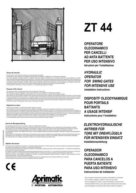
CARATTERISTICHE GENERALI<br />
- Studiato per utenze residenziali, l’ZT 44 è un operatore oleodinamico per cancelli ad ante battenti. Viene prodotto in due differenti versioni<br />
AP014 P5<br />
70<br />
121<br />
di portata pompa per utilizzarlo al meglio su ante di piccole e grandi dimensioni.<br />
- La versione con blocco idraulico in chiusura evita il ricorso ad elettroserratura garantendo la posizione di chiusura per ante di lunghezza<br />
inferiore a 1,8 metri.<br />
- Sblocco di emergenza: permette il comando manuale del cancello (da usarsi in assenza di corrente) con chiave personalizzata, facilmente<br />
accessibile attraverso un vano apribile situato sul cofano superiore dell'attuatore, di sicuro funzionamento e facile manovrabilità.<br />
- Sicurezza antischiacciamento garantita da sensibili valvole, tarabili in fase di installazione.<br />
GENERAL CHARACTERISTICS<br />
Specially designed for residential use, the ZT 44 is a hydraulic operator for swing gates. It is produced in two different pump flow-rate<br />
versions for use with small or large size gate leaves.<br />
- The version with the hydraulic closing lock avoids the use of electrical locking, and guarantees the closing position for gate leaves of length<br />
less than 1.8 meters.<br />
- Emergency release: allows the manual control of the gate (for use in the absence of electricity supply) with a personalized key, easily<br />
accessible via an opening compartment on the upper cover of the operator, safe to use and easily maneuverable.<br />
- “Non-crush” safety feature with sensitive valves, settable during installation.<br />
CARACTERISTIQUES GENERALES<br />
- Etudié pour le zones résidentielles, le dispositif oléodynamique ZT 44 est installé sur les grilles à portes battentes. Il est produit en deux versions<br />
avec des débits différents de la pompe pour l’usage sur portes de petites ou grandes dimensions.<br />
- Le modèle avec blocage hydraulique en fermeture; cela évite l'installation de l'électroserrure, car il assure la fermeture des portes ayant même<br />
une longueur de 1,8 mètres.<br />
- Déblocage d'urgence: il permet la commande manuelle pour les opérateurs (à utiliser en cas de manque de courant) avec clé personnalisée.<br />
Vous pouvez y accéder à travers un petit couvercle placé sur le coffret supérieur de l'opérateur et il est tres simple à utiliser.<br />
- Protection contre écrasement assurée par des clapets très sensibles, réglés en phase d'installation.<br />
ALLGEMEINE MERKMALE<br />
- Der elektrohydraulische Antrieb ZT 44 für Tore mit Drehflügeln ist eigens für Wohnhäuser entwickelt worden. Er wird mit 2 verschiedenen<br />
Pumpenleistungen geliefert und eignet sich besonders für Flügel großer und kleiner Dimensionen.<br />
- Bei der Version mit hydraulischer Sperrung im Schließvorgang erspart man sich den Einbau eines Elektroschlosses. Dabei bleibt die<br />
Schließstellung bei bis 1,8 m langen Flügeln gewährleistet.<br />
- Not-Entriegelung: Ermöglicht den Handantrieb des Tores (Stromausfall zu verwenden), mit persönlichem Schlüssel. Die Entriegelung ist<br />
leicht zugänglich durch einen kleinen Deckel am oberen Gehäuse des Antriebes.<br />
- Sicherheit vor Einquetschungen dank hochempfindlicher Ventile, die während der Installierung eingestellt werden.<br />
CARACTERISTICAS GENERALES<br />
- Estudiado para zonas recidenciales, ZT 44 es un operador oleodinámico para cancelos a puerta batiente. Viene producido en dos<br />
diferentes versiones, de llevada bomba para utilizarlo, al mejor, en puertas de pequeñas y grandes dimenciones.<br />
- La versión con bloqueo idraulico, serrado, evíta el recorrido a electrocerraduras, garantizando la posición de la serrada por puertas de<br />
longitud inferior a 1,8 metros.<br />
- Desbloque de emergencia: permite el comando manual del cancel (de usar en ausencia de electricidad) con llave personalizada,<br />
fácilmente accesible por medio de una ventanilla situada en el capó superior del actuador, de seguro funcionamiento y fácil<br />
manovrabilidad.<br />
- Seguridad anti-aplastamiento garantizada de válvulas sensibles, graduadas en la fase de instalación.<br />
AP004001<br />
B<br />
A<br />
C<br />
90<br />
MOD. ZT 44<br />
A (mm)<br />
B (mm)<br />
C (mm)<br />
1060<br />
732<br />
270<br />
A<br />
5
CONTROLLI PRELIMINARI<br />
Prima di definire il posizionamento in pianta degli attacchi occorre:<br />
- Scegliere il punto più idoneo, sull’anta, per posizionare in altezza l’attacco anteriore dell’attuatore. Nei limiti del possibile posizionarsi a<br />
metà dell'altezza dell'anta. Di norma il punto ideale è sempre la zona più robusta e meno soggetta a flessione dell’anta.Se non è presente<br />
sul cancello un fascione di profilato facente parte della struttura, occorre saldare nella zona di posizionamento attacco anteriore un<br />
adeguato supporto dello stesso per distribuire il carico su una zona ampia (B1A).<br />
- Verificare se il punto prescelto necessita di rinforzi o qualsiasi altra operazione di irrobustimento. Lo stesso controllo va effettuato sui<br />
pilastri di sostegno delle ante.<br />
- Per procedere al definitivo montaggio è necessario eseguire un completo controllo delle ante verificando che le stesse siano in buone<br />
condizioni e non presentino rotture o danneggiamenti.<br />
- Controllare che il movimento delle ante sia uniforme e le relative cerniere siano esenti da giochi ed attriti.<br />
- Verificare che le ante siano a piombo (perfettamente ferme in qualsiasi punto della rotazione) (B1B); controllare, ad ante completamente<br />
chiuse, che queste combacino uniformemente per tutta la loro altezza.<br />
- Verificare con un dinamometro che lo sforzo,misurato in punta d'anta, di apertura e chiusura delle ante non superi i 15 Kg. (147 N).<br />
Diversamente occorre riparare le cerniere in modo che le ante si possano movimentare a mano con facilità oppure, nella peggiore delle<br />
ipotesi, sostituirle.<br />
PRELIMINARY CHECKS<br />
Before deciding on the final position if the mountings, it is necessary to:<br />
- Choose the most suitable height on the gate leaf for the operator front mounting. If possible, it should be positioned halfway up the gate<br />
leaf. As a rule, the ideal point is always in the strongest area, where the flexing of the gate leaf has the least effect. If there is not a broad<br />
strip of steel in the gate framework, then a suitable support needs to be welded on in the area where the front mounting is to be positioned,<br />
in order to spread the load over a wide zone (B1A).<br />
- Check whether the chosen area needs reinforcing or strengthening in any way. Make the same check on the gate leaf support posts.<br />
- Before proceeding with the actual mounting, make a complete check on the gate leaves, making sure that they are in good condition, and<br />
not broken or damaged in any way.<br />
- Check that the movement of the gate leaves is uniform, and that the hinges have no play and do not rub.<br />
- Check that the gate leaves are plumb (when perfectly still at any point in the swing) (B1B); when the gates are completely closed, check<br />
that the closure is even throughout the whole height of the gate leaves.<br />
- Using a dynamometer to measure from the end of the gate leaf, check that the opening and closing effort of the gate leaves does not exceed<br />
15 kg (147 N). If the effort is excessive, then the hinges must be repaired so that the gate leaves can be moved easily by hand or, if repairs<br />
are impossible, the hinges must be replaced.<br />
CONTROLES PRELIMINAIRES<br />
Avant de définir le positionnement en plan des fixations, il faut:<br />
- Choisir la position la plus appropriée, sur le battant, afin de positionner en hauteur la patte avant de l'opérateur. S'il est possible, positionnezle<br />
près de la moitié de l'hauteur du battant. En général, la position optimale est toujours la plus solide et moins sujète aux déformations du<br />
battant. Si la structure du portail n'est pas douée d'une bande en profilé, soudez, dans la zone de positionnement de la fixation avant, un<br />
support prévu à cet effet afin de répartir la charge sur une surface plus grande (B1A).<br />
- Vérifiez si la position choisie a besoin de renforcements. Effectuez le même contrôle pour les piliers qui soutiennent les portes.<br />
- Avant de procéder au montage définitif, contrôlez si les vantaux sont en bonnes conditions ou si ils sont endommagées.<br />
- Contrôlez si le mouvement des vantaux est uniforme et si les charnières correspondantes ont du jeu ou du frottement.<br />
- Vérifiez que les vantaux soient parfaitement rigides dans tous les points de rotation (B1B). Avec les vantaux complètement fermés, contrôlez<br />
si ils joignent parfaitement dans toute leur hauteur.<br />
- A l'aide d'un dynamomètre, vérifiez que l'effort d'ouverture et fermeture calculé au bout des vantaux, ne dépasse pas 15 kg (147 N). Autrement,<br />
il faudra réparer les charnières de façon à ce que les vantaux peuvent être actionnés à la main ou, dans le pire des cas, il faudra les remplacer.<br />
B<br />
6<br />
AP014 P6
AP014 P7<br />
VORKONTROLLEN<br />
Vor Bestimmung der Drehpunkte sind folgende Arbeitsgänge erforderlich:<br />
- Die bestgeeignete Stelle am Flügel aussuchen zwecks Höheneinstellung des vorderen Drehpunktes des Antriebes. Den Drehpunkt nach<br />
Möglichkeit auf halber Flügelhöhe positionieren. Die ideale Stelle in der Regel der stabilere, der Flügelbiegung am wenigsten ausgesetzte<br />
Teil. Sofern sich am Tor kein strukturabhängiger Profilstab befindet, so ist an die für den vorderen Drehpunkt geeignete Stelle ein<br />
passender Halter aufzuschweißen. Damit wird die Belastung auf eine breite Fläche verteilt (B1A).<br />
- Prüfen, ob der ausgesuchte Punkt Verstärkungen oder sonstige Konsolidierungsarbeiten benötigt. Dasselbe gilt für die Stützpfeiler der<br />
Flügel.<br />
- Vor der endgültigen Montage ist eine gründliche Kontrolle der Flügel erforderlich. Nachprüfen, ob diese in tadellosem Zustand sind und<br />
weder Brüche noch Schäden aufweisen.<br />
- Prüfen, ob sich Flügel gleichmäßig und Scharniere reibungslos und spielfrei bewegen.<br />
- Prüfen, ob Flügel lotrecht sind (ob sie an jedem Drehpunkt einwandfrei fest aufsitzen) (B1B). Mit Flügeln in voll geschlossenem Zustand<br />
kontrollieren, ob diese um ihre ganze Höhe gleichmäßig aufeinanderpassen.<br />
- Mit einem Dynamometer feststellen, ob die (am Flügelende ermittelte) Öffnungs- und Schließkraft der Flügel unter 15 kg (147 N) liegt.<br />
Falls nicht, sind die Scharniere so zu richten, daß Flügel leicht von Hand bewegt werden können. Schlimmstenfalls auswechseln.<br />
CONTROLES PRELIMINARES<br />
Antes de definir la coloración en Planta de las conexiones, ocurre:<br />
- Escoger el punto más idóneo, en la puerta, para posicionar en altura la conexión anterior del actuador. En los límites del posible, colocarse<br />
a la mitad de la altura de la puerta. De norma, el punto ideal es siempre la zona más robusta y menos sujeta a flexiones de la puerta. Si<br />
no es presente en el cancel una faja de perfilado haciendo parte de la estructura, ocurre soldar en la zona de posicionamiento conexión<br />
anterior, un adecuado soporte del mismo para distribuir el peso en una zona amplia (B1A).<br />
- Verificar si el punto preescogido necesita de refuerzos o cualquier otra operación de robustecimiento. El mismo control va efectuado en<br />
los postes de sostén de las puertas.<br />
- Para proceder al montaje definitivo es necesario efectuar un completo control de las puertas, verificando que las mismas sean en buenas<br />
condiciones, no presenten roturas o daños.<br />
- Controlar que el movimiento de las puertas sea uniforme y las relativas bisagras estén ausentes de juegos y fricciones.<br />
- Verificar que las puertas sean aplomadas (perfectamentes paradas en cualquier punto de la rotación) (B1B); controlar, a puertas<br />
completamente cerradas, que éstas concuerden uniformemente en toda su altura.<br />
- Verificar con un dinamómetro que el esfuerzo, medida en punta de puerta, de apertura y cerrado de las puertas no superen los 15 Kgs.<br />
(147 N). Diversamente ocurre reparar las bisagras en modo que las puertas se puedan mover a mano con facilidad o, en la peor de las<br />
hipótesis, sustituirlas.<br />
AP004002<br />
B1A<br />
AP004002<br />
B1B<br />
filo a piombo<br />
plumb line<br />
fil à piomb<br />
Senklot<br />
plomada<br />
B<br />
7
DISPOSITION DES COMPOSANTS (B2)<br />
A - Clignotant <strong>Aprimatic</strong> (positionnez-le dans une place bien visibile des deux côtés de passage)<br />
B - Photocellule de sécurité <strong>Aprimatic</strong><br />
C - Dispositif de contrôle manuel à clé (magnétique, digitale, par clavier, mécanique, etc.)<br />
D - Dispositif de contrôle <strong>Aprimatic</strong> à microprocesseur placé dans un coffret étanche (à positionner, si possible, à l'abri des agents<br />
atmosphériques)<br />
E - Récepteur télécommande (possible installation dans le clignotant) <strong>Aprimatic</strong><br />
F - Boîte de dérivation étanche pour l'alimentation de l'opérateur (recommandée) - il faut la positionner da façon à ce que les câbles ne soient<br />
pas sujets à des efforts dangereux pendant le fonctionnement<br />
G - Antenne (option)<br />
H - Opérateurs <strong>Aprimatic</strong> série ZT<br />
I - Electro-serrure<br />
L - Arrêt mécanique pendant l'ouverture<br />
M - Arrêt mécanique pendant la fermeture<br />
N - Mise à terre des structures métalliques<br />
N.B. Pour d'autres dispositifs de sécurité (options), voir le tarif.<br />
DISPOSIZIONE DEI COMPONENTI (B2)<br />
A - Lampeggiatore <strong>Aprimatic</strong> (posizionare in un punto ben visibile da entrambi i lati del transito)<br />
B - Fotocellula di sicurezza <strong>Aprimatic</strong><br />
C - Dispositivo di comando manuale a chiave (magnetica, digitale, combinatore a tastiera, meccanica, ecc.)<br />
D - Apparecchiatura di comando <strong>Aprimatic</strong> a microprocessore in contenitore stagno (posizionare, possibilmente, al riparo da agenti<br />
atmosferici)<br />
E - Radioricevente telecomando (possibilità di inserimento all'interno del lampeggiatore) <strong>Aprimatic</strong><br />
F - Scatola derivazione stagna alimentazione attuatore (consigliata) - posizionare in modo che i cavi non subiscano tensioni pericolose<br />
durante il movimento<br />
G - Antenna (optional)<br />
H - Attuatori <strong>Aprimatic</strong> serie ZT<br />
I - Elettroserratura<br />
L - Arresto meccanico in apertura<br />
M - Arresto meccanico in chiusura<br />
N - Messa a terra delle strutture metalliche<br />
N.B.: Per ulteriori dispositivi di sicurezza (optional) consultare il listino prezzi.<br />
COMPONENTS LAYOUT (B2)<br />
A - <strong>Aprimatic</strong> flashing warning/courtesy lamp (to be positioned at a point that is clearly visible from both approaches)<br />
B - <strong>Aprimatic</strong> safety photocell<br />
C - Manual key-operated control unit (magnetic, digital, keyboard combination lock, mechanical, etc.)<br />
D - <strong>Aprimatic</strong> microprocessor control unit in watertight container (if possible, to be fitted in a position that is sheltered from<br />
atmospheric agents)<br />
E - <strong>Aprimatic</strong> remote control radio receiver (can be fitted inside the flashing lamp)<br />
F - Watertight operator electricity supply junction box (recommended) - to be positioned so that the cables are not subject<br />
to dangerous stretching during the movement of the gate leaves<br />
G - Antenna (optional)<br />
H - <strong>Aprimatic</strong> ZT series operators<br />
I - Electric lock<br />
L - Open position gate stop<br />
M - Closed position gate stop<br />
N - Ground connection for metal framework<br />
N.B.: Consult the price-list for additional (optional) safety devices.<br />
B<br />
8<br />
AP014 P8
AP014 P9<br />
ANORDNUNG DER BAUTEILE (B2)<br />
A - APRIMATIC-Warnblinker (an eine Stelle anbringen, die von beiden Verkehrsrichtungen gut sichtbar ist)<br />
B - APRIMATIC-Sicherheitslichtschranke<br />
C - Schlüsselschalter (magnetisch, digital, tastenbetätigt, mechanisch etc.)<br />
D - Mikroprozessorbetätigte APRIMATIC-Steuerung in wasserdichtem Gehäuse (möglichst wettergeschützt unterbringen)<br />
E - Ferngesteuerter APRIMATIC-Funkempfänger (Einbau innerhalb der Warnblinkers möglich)<br />
F - Wasserdichte Abzweigdose für Antriebsanschluß (empfohlen). So positionieren, daß Kabel während der Bewegung nicht gefährlichen<br />
Spannungen unterliegen.<br />
G - Antenne (Option)<br />
H - APRIMATIC-Antriebe Baureihe ZT<br />
I - Elektroschloß<br />
L - Mechanischer Anschlag bei Öffnung<br />
M - Mechanischer Anschlag bei Schließung<br />
N - Erdung d. Metallstrukturen<br />
Anmerkung: Weitere Sicherheitsvorrichtungen entnehmen Sie aus unserer Preisliste.<br />
DISPOSICION DE LOS COMPONENTES (B2)<br />
A - Intermitente <strong>Aprimatic</strong> (colocar en un punto bien visible a ambos lados del tránsito)<br />
B - Célula fotoeléctrica de seguridad <strong>Aprimatic</strong><br />
C - Dispositivo de comando manual a llave (magnética, digital, combinador a teclado, mecánica, etc.)<br />
D - Equipo de comando <strong>Aprimatic</strong> a microprocesador en recipiente impermeable (colocar, posiblemente, a reparo de agentes<br />
atmosféricos)<br />
E Radio-receptor teledirigido (posibilidad de incluirlo al interno de la intermitente) <strong>Aprimatic</strong><br />
F - Caja derivación impermeable alimentación actuador (aconsejada) - colocar en modo que los cables no sufran tensiones peligrosas<br />
durante el movimiento<br />
G - Antena (opcional)<br />
H - Actuadores <strong>Aprimatic</strong> serie ZT<br />
I - Electrocerradura<br />
L - Parada mecánica en apertura<br />
M - Parada mecánica en cerrado<br />
N - Puesta en tierra de la estructura metálica<br />
NOTA: Para ulteriores dispositivos de seguridad (opcionales) consultar la lista de precios.<br />
AP004003<br />
B 2<br />
B<br />
9
VERIFICA SCELTA AUTOMAZIONE<br />
Prima di effettuare il montaggio è necessario verificare la scelta dell’automazione in funzione delle caratteristiche e delle dimensioni dell'elemento da<br />
movimentare. L’operatore oleodinamico ZT 44 è compatibile con gli elementi sotto riportati.<br />
AVVERTENZA<br />
• La giusta scelta dell’automazione garantisce un corretto funzionamento del gruppo e riduce al minimo la possibilità di guasti.<br />
• L’attuatore ZT 44, se correttamente installato, è in osservanza alle norme di sicurezza riportate sulla pubblicazione UNI 8612.<br />
Elenco delle versioni:<br />
C: Blocco idraulico solo in chiusura (con blocco inaccessibile ad anta aperta)<br />
SF: Senza blocco idraulico - frenato (anta movimentabile a mano con minima resistenza, se movimentata lentamente; dispone di un dispositivo di sblocco<br />
per facilitare l'apertura - necessita elettroserratura - da utilizzare in zone ventose)<br />
ATTENZIONE<br />
• Le versioni sopra riportate sono consigliabili anche in presenza di ante tamponate (con l'attuatore inaccessibile ad anta aperta).<br />
• Il modello in versione C non deve essere installato su ante di lunghezza superiore a 1,8 mt.<br />
ATTENZIONE<br />
La velocità periferica dell'anta deve sempre essere inferiore a 12 mt./min. in ottemperanza alle norme UNI 8612; inoltre è importante evitare l'impiego<br />
di attuatori veloci su ante larghe per evitare forti battimenti sugli arresti del cancello (consultare la tabella sotto riportata).<br />
RIPORTIAMO DI SEGUITO L'ELENCO DEI MODELLI DISPONIBILI<br />
CHOOSING THE TYPE OF AUTOMATION<br />
Before mounting, the type of automation must be decided on, on the basis of the characteristics and dimensions of the gate leaf to be operated. The ZT 44<br />
hydraulic operator is compatible with the types of gate leaf listed below.<br />
IMPORTANT<br />
• If the right choice is made in the type of automation, the efficient operation of the unit will be assured and the possibility of breakdowns will be<br />
reduced to a minimum.<br />
• The ZT 44 operator, if installed correctly, conforms to all the safety standards.<br />
List of versions:<br />
C: Hydraulic lock for closing only (with lock inaccessible when the gate is open)<br />
SF: No hydraulic lock - braking action (the gate leaf can be moved by hand with a minimum of resistance, if moved slowly; there is also a release lock to<br />
facilitate opening - needs an electric lock - for use in windy zones)<br />
NOTE<br />
• The versions listed above are recommended for use with solid gate leaves (with the operator inaccessible when the gate is open)<br />
• The C version model must not be fitted on gate leaves of length exceeding 1.8 m<br />
NOTE<br />
The peripheral speed of the gate leaf must always be less than 12 m/min. in order to conform to regulations; also, it is important to avoid the use<br />
of high speed operators on wide gate leaves, as this could cause the gate leaves to bang violently against the gate stop (see table, below).<br />
THE LIST OF AVAILABLE MODELS IS AS FOLLOWS:<br />
CONTROLE DE L’AUTOMATISATION<br />
Avant d'effectuer le montage, vérifiez l'automatisation par rapport aux caractéristiques et aux dimensions de l'élément à actionner. L'opérateur oléodynamique<br />
ZT 44 sont compatibles avec les éléments sousmentionnés.<br />
ATTENTION !<br />
• Une bonne automatisation assure un fonctionnement correct du groupe et réduit les pannes.<br />
• L'opérateur ZT 44, si bien installé, est conforme aux normes de sécurité.<br />
Liste des modèles:<br />
C: Blocage hydraulique seulement en fermeture (sans blocage avec porte ouverte)<br />
SF: Sans blocage hydraulique - freiné (si la porte est actionnée lentement, on va relever une petite résistance; il est doué d'un dispositif de déblocage pour<br />
faciliter l'ouverture - l'électro-serrure est nécessaire - à utiliser dans les zones venteuses).<br />
ATTENTION !<br />
• Les modèles susmentionnés sont à utiliser en cas de vantaux pleins ( avec l'opérateur inaccessible avec porte ouverte).<br />
• Le modèle en version C ne doit pas être installé sur des vantaux ayant une longueur supérieure à 1,8 m.<br />
ATTENTION !<br />
La vitesse périfphérique de la porte doit toujours être inférieure à 12 m/min. Conformément aux normes , n'installez pas les opérateurs rapides sur<br />
des vantaux larges afin d'éviter de forts claquements sur les arrêts du portail (voir le schéma).<br />
LISTE DES MODELES DISPONIBLES SELON LES DIFFERENTES VERSIONS<br />
B<br />
10<br />
AP014 P10
AP014 P11<br />
PRÜFEN DER ANTRIEBSVERSION<br />
Vor Beginn des Einbaus sollte überlegt werden, welche Antriebsversion am besten dem Anwendungszweck entspricht, unter Berücksichtigung der<br />
Eigenschaften und Abmessungen des zu bewegenden Objekts. Der elektrohydraulische Antrieb ZT 44 kann mit untenstehenden Ausführungen kombiniert<br />
werden.<br />
HINWEIS<br />
• Die korrekte Wahl des bestgeeigneten Antriebes sichert einen sachgemäßen Betrieb und verringert zugleich allfällige Störfälle.<br />
• Der Antrieb ZT 44 entspricht (sofern fachgerecht installiert) den geltenden Sicherheitsnormen.<br />
Lieferbare Ausführungen<br />
C: Elektrohydraulische Blockierung im Schließvorgang (ohneBlockierung bei offenem Flügel)<br />
SF: Ohne elektrohydraulische Blockierung, gebremst (Flügel kann mit geringem Widerstand langsam handbewegt werden. Eine Notentriegelung<br />
erleichtert den Öffnungsvorgang; Elektroschloß erforderlich; empfehlenswert für besonders windige Gebiete)<br />
ACHTUNG!<br />
• Obige Ausführungen empfehlen sich bei mit Platten verkleideten Flügeln (bei offenem Flügel kann Antrieb nicht erreicht werden).<br />
• Ausführungen C nicht auf Flügel montieren, die länger als 1,8 Meter m sind.<br />
ACHTUNG!<br />
Die Umfangsgeschwindigkeit der Flügel muß laut Sicherheitsnormen stets niedriger als 12 m/Min. sein. Demgemäß sollten bei breiten Flügeln keine<br />
schnellen Antriebe eingesetzt werden, um allzu starke Schläge auf die Toranschläge zu vermeiden (siehe untenstehende Tabelle).<br />
PRUEBA ELECCION AUTOMATIZACION<br />
Antes de efectuar el montaje es necesario verificar la escogencia de la automatización, en función de las características y de las dimensiones del elemento<br />
a mover. El operador oleodinámico ZT 44, en las varias versiones, es compatible con los elementos abajo indicados.<br />
<strong>AD</strong>VERTENCIA<br />
• La justa escogencia de la automatización garantiza un funcionamiento correcto del grupo y reduce al mínimo la posibilidad de daños.<br />
• El actuador ZT 44, si es corréctamente instalado, es en observación a las normas de seguridad reportadas en la publicación UNI 8612.<br />
Lista de las versiones:<br />
C: loqueo hidráulico solo en cerrado (con bloqueo inaccesible a puerta abierta)<br />
SF: Sin bloqueo hidráulico - frenado (puerta movible a mano con mínima resistencia, si es movida lentamente; posee un dispositivo de desbloqueo para<br />
facilitar la apertura - necesita electrocerradura - de utilizar en zona ventosa)<br />
ATENCION<br />
• Las versiones antes indicadas son aconsejadas en presencia de puertas rellenadas (con el actuador inaccesible a puerta abierta)<br />
• El modelo en versione C NO DEBE ser instalado en puertas de longitud superior a 1,8 metros.<br />
ATENCION<br />
La velocidad periférica de la puerta debe siempre ser inferior a 12 m./min. en obediencia a las normas UNI 8612; además es importante evitar el<br />
empleo de actuadores veloces en puertas anchas para evitar fuertes batidas en las paradas del cancel (consultar el diagrama abajo indicado).<br />
INDICAMOS A CONTINUACION LA LISTA DE LOS MODELOS DISPONIBLES<br />
LUNGHEZZA ANTA<br />
LENGHT OF GATE LEAF<br />
LONGEUR VANTAUX<br />
FLÜGELLÄNGE<br />
ANCHURA PUERTA<br />
da 1,2 a1,8 mt.<br />
da 1,2 a 3 mt.<br />
MODELLI DISPONIBILI<br />
AVAIABLE MODELS<br />
MODELES DISPONIBLES<br />
LIEFERBARE MODELLE<br />
MODELOS DISPONIBLES<br />
ZT 44C<br />
ZT 44SF<br />
B 11
VERIFICA COMPONENTI ATTUATORE<br />
Verificare che la sigla del modello riportata sulla scatola da imballo<br />
dell'attuatore corrisponda a quella riportata sulla targhetta dell'attuatore<br />
stesso (B3).<br />
Controllare inoltre, prima di iniziare il montaggio, che l’imballo contenga<br />
tutti i componenti elencati nella pagina successiva in figura B4 e che<br />
gli stessi non siano danneggiati.<br />
O<strong>PER</strong>ATOR COMPONENTS CHECK<br />
Check that the model code displayed on the operator packaging<br />
corresponds to the code on the identification plate on the<br />
operator itself (B3).<br />
Also, before starting with the mounting procedure, check that<br />
the packaging contains all the components listed in fig. B4 on<br />
the next page, and that none of the components are damaged.<br />
CONTRÔLE DES COMPOSANTS DE<br />
L’O<strong>PER</strong>ATEUR<br />
Vérifiez que l’indication du modèle sur l’emballage de<br />
l’opérateur correspond à celle indiquée sur la plaque de<br />
l’opérateur même (B3).<br />
Avant de commencer le montage, contrôlez que l’emballage<br />
contienne tous les composants indiqués à la page suivante et<br />
qu’il ne soit pas endommagés.<br />
PRÜFEN DER ANTRIEBSTEILE<br />
Prüfen, ob die Bezeichung der Antriebsausführung die, auf<br />
dem Verpackungsarten erscheint, mit der Bezeichnung auf<br />
dem Schild des Antriebs übereinstimmt (B3).<br />
Außerdem ist vor Beginn der Montage sorgfältig zu prüfen, ob<br />
alle auf nachstehender Seite unter Abb. B4 aufgelisteten Teile<br />
mit verpackt wurden bzw. ob sie Beschädigungen erlitten.<br />
PRUEBA COMPONENTES ACTU<strong>AD</strong>OR<br />
Verificar además, que la sigla del modelo indicada en la caja<br />
de embalaje del actuador, corresponda a la reportada en la<br />
tarjeta del actuador mismo (B3).<br />
Antes de iniciar el montaje controlar que el embajale contenga<br />
todos los componentes indicados en la fig. B4 y que los<br />
mismos no se encuentren dañados.<br />
AP004004<br />
B 3<br />
12<br />
AP014 P12
AP014 P13<br />
ELENCO DEI<br />
COMPONENTI (B4)<br />
Pos. Descrizione<br />
1 Attuatore<br />
2 Cofano superiore<br />
3 Serratura sblocco<br />
4 Dado<br />
5 Snodo sferico<br />
6 Seeger<br />
7 Carter protezione<br />
stelo<br />
8 Coperchio carter<br />
protezione stelo<br />
9 Attacco posteriore<br />
10 Boccola<br />
11 Perno posteriore<br />
12 Seeger<br />
13 Perno forcella<br />
14 Forcella<br />
15 Dado autobloccante<br />
16 Condensatore<br />
17 Attacco anteriore<br />
18 Vite autofilettante<br />
19 Dima<br />
20 Chiave sblocco<br />
21 Guarnizione<br />
A Gruppo attacco<br />
anteriore completo<br />
B Gruppo attacco<br />
posteriore completo<br />
AP004005<br />
B 4<br />
LIST OF<br />
COMPONENTS (B4)<br />
Pos. Description<br />
1 Operator<br />
2 Upper cover<br />
3 Relese lock<br />
4 Nut<br />
5 Ball joint<br />
6 Snap ring<br />
7 Rod protection casing<br />
8 Rod protection casing<br />
cover<br />
9 Rear mounting<br />
10 Bushing<br />
11 Rear pin<br />
12 Snap ring<br />
13 Fork pin<br />
14 Fork<br />
15 Locknut<br />
16 Capacitor<br />
17 Front mounting<br />
18 Self-tapping screw<br />
19 Template<br />
20 Release key<br />
21 Seal<br />
A Complete front<br />
mounting assembly<br />
B Complete rear<br />
mounting assembly<br />
10<br />
14 15<br />
9<br />
11 12 13<br />
4 5 6 18<br />
17<br />
LISTE DES<br />
COMPOSANTS (B4)<br />
Pos. Description<br />
1 Opérateur<br />
2 Carter supérieur<br />
3 Serrure deblocage<br />
4 Ecrou<br />
5 Rotule<br />
6 Seeger<br />
7 Carter de protection<br />
tige<br />
8 Couvercle carter de<br />
protection tige<br />
9 Patte arrière<br />
10 Entretoises<br />
11 Pivot arrière<br />
12 Seeger<br />
13 Axe<br />
14 Fourche<br />
15 Ecrou auto-bloquant<br />
16 Condensateur<br />
17 Patte avant<br />
18 Vis auto-taraudeuse<br />
19 Gabarit<br />
20 Clé déblocage<br />
21 Adhésifs<br />
22 Couvercle<br />
A Groupe fixation avant<br />
complet<br />
B Groupe fixation<br />
arrière complet<br />
B<br />
12<br />
7<br />
A<br />
18<br />
20<br />
LISTE DER<br />
ANTRIEBSTEILE (B4)<br />
Pos. Beschreibung<br />
1 Antrieb<br />
2 Abdeckung oben<br />
3 Entriegelungsschloss<br />
4 Mutter<br />
5 Kugelgelenk<br />
6 Seegerring<br />
7 Kolbenstangenabdeckung<br />
8 Deckel f.<br />
Kolbenstangenabdeckung<br />
9 Befestigung hinten<br />
10 Buchse<br />
11 Bolzen hinten<br />
12 Seegerring<br />
13 Gabelbolzen<br />
14 Gabel<br />
15 Selbstsperrende<br />
Mutter<br />
16 Kondensator<br />
17 Drehpunkt vorn<br />
18 Selbstsichernde<br />
mutter<br />
19 Schablone<br />
20 Schlüssel z. Entriegeln<br />
21 Dichtung<br />
A Gruppe f.<br />
Vorderbefestigung,<br />
kompl.<br />
B Gruppe f.<br />
Hinterbefestigung,<br />
kompl.<br />
2<br />
1<br />
8<br />
3<br />
16<br />
LISTA DE LAS<br />
PIEZAS (B4)<br />
Pos. Descripción<br />
1 Actuador<br />
2 Capó<br />
3 Cerradura de<br />
desbloque<br />
4 Dado<br />
5 Articulación esférica<br />
6 Seeger<br />
7 Carter protección<br />
barra<br />
8 Tapa carter<br />
protección barra<br />
9 Conexión posterior<br />
10 Distancial<br />
11 Perno posterior<br />
12 Seeger<br />
13 Perno horquilla<br />
14 Horquilla<br />
15 Dado auto-blocante<br />
16 Condensador<br />
17 Conexión anterior<br />
18 Tornillo antienroscante<br />
19 Calibre de<br />
comprobación<br />
20 Llaves de desbloco<br />
21 Empacadura<br />
A Grupo conexión<br />
anterior completo<br />
B Grupo conexión<br />
posterior completo<br />
B<br />
13
PREPARAZIONE AL MONTAGGIO<br />
Il montaggio dell’attuatore richiede una serie di lavori di preparazione al gruppo da movimentare da eseguirsi direttamente sul luogo dell'installazione;<br />
è quindi necessario premunirsi dell'attrezzatura adatta che consenta all'installatore la massima autonomia durante il lavoro.<br />
AVVERTENZA<br />
L'elenco dell'utensileria necessaria è riportato nella figura, comprensiva di tabella, (B5).<br />
Attrezzatura base e materiale di consumo occorrente<br />
- Mola a disco elettrica - alimentazione 230 V.<br />
- Occhiali di protezione<br />
- Saldatrice elettrica - alimentazione:<br />
230 V./100 Amp. minimo<br />
- Maschera di protezione<br />
- Elettrodi Ø 2 minimo<br />
- Saldatore da stagno<br />
- Trapano elettrico di potenza adeguata<br />
alimentazione 230 V.<br />
- Punte da trapano<br />
- Fresa a tazza ø 67 per fori alloggiamento fotocellule<br />
e pulsantiere<br />
- Cavo di prolunga per attrezzatura elettrica<br />
- Cavo elettrico sez. 1,5 mm 2 vari colori + capicorda<br />
vario tipo<br />
- Forbici da elettricista<br />
- Pinze per capicorda<br />
- Tester<br />
- Calibro ventesimale<br />
- Metro<br />
- Goniometro<br />
- Dinamometro<br />
- Filo a piombo<br />
- Livella a bolla (tridimensionale)<br />
- Grasso tipo grafitato.<br />
- Olio tipo AprimOil HC 13<br />
(olio espressamente formulato per <strong>Aprimatic</strong>)<br />
- Bomboletta Zincospray<br />
- Vernice antiruggine<br />
PREPARATIONS FOR MOUNTING<br />
PREPARATION POUR L’INSTALLATION<br />
- Pennelli per verniciatura<br />
- Diluente per pulizia pennelli<br />
- Spazzola metallica<br />
- Lime varie<br />
- Seghe da ferro<br />
- Punte da tracciatura<br />
- Martello<br />
- Scalpello per acciaio e per<br />
muratura<br />
- Salviette detergenti<br />
- Carta per asciugatura mani<br />
- Cassetta "Pronto soccorso"<br />
To mount the operator, a number of preparatory on-site jobs need to be done on the structure that is to be moved; for this, it is better to be equipped<br />
with the correct tools, so that the installer is able to work independently.<br />
IMPORTANT<br />
The list of required tools is shown in the illustration and table (B5).<br />
Basic tools and expendable material requirements<br />
- Electric disk grinder - 230 V<br />
- Protective goggles<br />
- Electric welder - min. power: 230 V/100 amp<br />
- Protective mask<br />
- Electrodes - min. Ø 2<br />
- Soldering iron<br />
- Suitably powered electric drill - 230 V<br />
- Drill bits<br />
- Hollow cutter Ø 67 for photocell and control<br />
panel mounting holes<br />
- Extension lead for welder<br />
- Electric cable cross-section 1.5 mm 2 , various<br />
colors + various types of cable end caps<br />
- Electrical scissors<br />
- Pliers for cable end caps<br />
- Tester<br />
- 1/20 gauge<br />
- Rule<br />
- Detergent wipes<br />
- Paper hand-towels<br />
- First aid kit<br />
- Goniometer<br />
- Dynamometer<br />
- Plumb line<br />
- Spirit level (3-dimensional)<br />
- Graphitized-type grease<br />
- Oil - AprimOil HC 13 (specially formulated<br />
for <strong>Aprimatic</strong>)<br />
- Zincospray cylinder<br />
- Anti-rust paint<br />
- Paintbrushes<br />
- Thinner for cleaning paintbrushes<br />
- Wire brush<br />
- Various files<br />
- Hacksaws<br />
- Scribers<br />
- Hammer<br />
- Chisel for steel and masonry<br />
Pour l'installation de l'opérateur, preparez le portail directement sur le lieu d'installation. Il faut disposer de l'équipement prevu à cet effet qui fournit à<br />
l'installateur une autonomie totale pendant le travail.<br />
ATTENTION !<br />
La liste des outils nécessaires est indiquée dans la figure contenant le tableau (B5).<br />
Outils de base et matériel nécessaire<br />
- Meule soucoupe électrique - alimentation 230 V<br />
- Lunettes de protection<br />
- Soudeuse électrique - alimentation:<br />
230V/100 Amp. minimum<br />
- Masque de protection<br />
- Electrodes Ø 2 minimum<br />
- Soudeur à l'étain<br />
- Perceuse électrique de puissance conforme à<br />
l'alimentation 230V<br />
- Langues de carpe<br />
- Fraise à godet Ø 67 pour trous de logement<br />
photocellules et tableau à poussoir<br />
- Câble de rallonge pour équipement électrique<br />
- Câble électrique section 1,5 mm 2 de différentes<br />
couleures et cosses de différents types<br />
- Ciseaux pour électricien<br />
- Pinces pour cosses<br />
- Tester<br />
- Jauge vingtième<br />
- Mètre<br />
- Goniomètre<br />
- Dynamomètre<br />
- Fil à plomb<br />
- Niveau à bulle d'aire (tridimensionnel)<br />
- Graisse graphitée<br />
- Huile AprimOil HC13<br />
(formulé expressement pour <strong>Aprimatic</strong>)<br />
- Bombe Zincospray<br />
- Vernis anti-rouille<br />
- Brosses pour vernissage<br />
- Solvant pour le nettoyage des brosses<br />
- Brosse métallique<br />
- Limes<br />
- Scie à fer<br />
- Pointes à tracer<br />
- Marteau<br />
- Fermoir pour acier et maçonnerie<br />
- Serviettes<br />
- Papier pour les mains<br />
- Pharmacie portative<br />
B<br />
14<br />
AP014 P14
AP014 P15<br />
MONTAGEVORBEREITUNGEN<br />
Zum Einbau des Antriebs ist vor Ort eine Reihe von Vorarbeiten am Tor erforderlich. Es ist daher eine geeignete Werkzeugausrüstung mitzunehmen,<br />
damit der Installateur weitgehend selbständig arbeiten kann.<br />
HINWEIS<br />
Die Liste der erforderlichen Werkzeuge ist aus nebenstehender Abbildung und Tabelle (B5) zu entnehmen.<br />
Grundausrüstung und erforderliches Verbrauchsmaterial<br />
- Elektrische Tellerscheibe, 230 V<br />
- Schutzbrille<br />
- Elektroschweißgerät, 230 V /100 A Min.<br />
- Schutzmaske<br />
- Elektroden Ø 2 mind.<br />
- Schweißgerät f. Zinn<br />
- Elektrobohrer mit angemessener<br />
Leistung, 230 V<br />
- Bohrspitzen<br />
- Topffräser Ø 67 zum Ausbohren der Sitze<br />
für Lichtschranken und Tastaturen<br />
- Verlängerungskabel für Elektrogeräte<br />
- Elektrokabel in versch. Farben,<br />
Querschnitt 1,5 mm 2 + Kabelschuhe<br />
verschiedener Art<br />
- Elektrikerschere<br />
- Zange für Kabelschuh<br />
- Tester<br />
- Lehre<br />
- Meßband<br />
- Winkelmesser<br />
- Dynamometer<br />
- Senkblei<br />
- Wasserwaage (3-dimensional)<br />
- Graphitschmiermittel<br />
- Öl Typ Aprim Oil HC13 (Spezialöl für<br />
APRIMATIC)<br />
- Zinkflasche<br />
- Rostschutzlack<br />
- Pinsel für Lockierung<br />
- Verdünner zum Pinselreinigen<br />
- Metallbürste<br />
- Verschiedene Feilen<br />
- Eisensägen<br />
- Reißnadeln<br />
- Hammer<br />
- Stahl- und Steinmeißel<br />
- Reinigungsservietten<br />
- Saugpapier<br />
- Erste-Hilfe-Kassette<br />
PREPARACION AL MONTAJE<br />
El montaje del actuador requiere una serie de trabajos de preparación al grupo a moverse, de efectuarse diréctamente en el sitio de la instalación;<br />
y por tanto, es necesario proveerse del equipo adapto que consienta al instalador la máxima autonomía durante el trabajo.<br />
<strong>AD</strong>VERTENCIA<br />
La lista de los utensilios necesarios es llevado en la figura, comprendida de tabla, (B5).<br />
Equipo base y material de consumo ocurrente<br />
- Resorte a disco eléctrico, alimentación: 230V.<br />
- Anteojos de protección<br />
- Soldador eléctrico, alimentación:<br />
230V/100 Amp. mínimo<br />
- Máscara de protección<br />
- Electrodos Ø 2 mínimo<br />
- Soldador de estaño<br />
- Taladro eléctrico de potencia adecuada,<br />
alimentación: 230V<br />
- Mecha de taladro<br />
- Fresa a taza Ø 67 para foros alojamiento<br />
célula fotoeléctrica y comando de pulsantes<br />
- Cable de extensión para equipo eléctrico<br />
- Cable eléctrico sec. 1,5 mm 2 varios colores<br />
más terminales de varios tipos<br />
AP004006<br />
B 5<br />
2<br />
2<br />
6 5 4 7 3<br />
1<br />
- Tijeras de electricista<br />
- Pizas para terminales<br />
- Tester<br />
- Calibro ventesimal<br />
- Metro<br />
- Goniómetro<br />
- Dinamómetro<br />
- Hilo a plomo<br />
- Nivel de burbuja (tridimensional)<br />
- Grasa tipo grafitado<br />
- Aceite tipo AprimOil HC 13 (aceite expresamente<br />
formulado para <strong>Aprimatic</strong>)<br />
- Bombonita spray de cinc<br />
- Pintura antioxidante<br />
- Pinceles para pintar<br />
POS.<br />
1<br />
2<br />
3<br />
4<br />
5<br />
6<br />
7<br />
- Disolvente para limpieza pinceles<br />
- Cepillo metálico<br />
- Limas varias<br />
- Sierra de hierro<br />
- Punta de trazado<br />
- Martillo<br />
- Cincel para acero y mampostería<br />
- Servilletas detergentes<br />
- Papel para secarse las manos<br />
- Cajita "pronto socorro"<br />
UTENSILXI/TOOL/OUTIL/WERKZEUG/UTENSILO<br />
Cacciavite / Screwdriver / Tournevis / Schraubendreher / Destornillador<br />
Pinza per seeger su albero / Gripper for snap ring on shaft / Pince pour<br />
seeger sur axe / Zange für Seegerring / Pinza para seeger sobre eje<br />
Cacciavite TC / Screwdriver TC / Tournevis TC / Schraubendreher TC<br />
/ Destornillador TC<br />
Chiave combinata 12 / Combination wrench 12 / Clé combinée 12 /<br />
Kombischlüssel 12 / Llave combinada 12<br />
Chiave combinata 13 / Combination wrench 13 / Clé combinée 13 /<br />
Kombischlüssel 13 / Llave combinada 13<br />
Chiave combinata 14 / Combination wrench 14 / Clé combinée 14 /<br />
Kombischlüssel 14 / Llave combinada 14<br />
Chiave combinata 17 / Combination wrench 17 / Clé combinée 17 /<br />
Kombischlüssel 17 / Llave combinada 17<br />
USAG 326/5x150<br />
USAG 128/P/10÷25<br />
USAG 326 TC/2<br />
USAG 285/12<br />
USAG 285/13<br />
USAG 285/14<br />
USAG 285/17<br />
B 15
POSIZIONAMENTO ATTACCHI<br />
Nella tabella seguente (C1) sono riportati i dati consigliati per definire la posizione degli attacchi dell'attuatore rispetto al centro di rotazione dell'anta.<br />
Determinando le quote A e B si stabiliscono:<br />
- La corsa utile (C) del pistone<br />
- La velocità periferica dell'anta<br />
- L'angolo di massima apertura dell'anta<br />
- La tenuta del blocco in relazione alla quota E (che deve sempre risultare inferiore a B quando l'attuatore è dotato di blocco idraulico); la quota<br />
E si ottiene, in pratica, misurando la distanza dal fulcro attacco anteriore all'asse della cerniera del cancello (vedi fig. C1)<br />
AVVERTENZA<br />
• La somma di A+B corrisponde alla corsa utile del pistone (C) per ottenere un'apertura dell'anta di 90°.<br />
• Il valore minimo delle quote A e B è di 70 mm, quello massimo di 130 mm.<br />
• Le quote A e B, per avere velocità periferiche uniformi, devono essere il più possibile uguali tra loro.<br />
• Per oltrepassare i 90° di apertura d'anta occorre, dopo avere individuato le quote A e B ottimali per il montaggio, diminuire la quota B<br />
quel tanto che basta a raggiungere l'angolo di apertura desiderato, facendo attenzione alla quota Y per evitare interferenze dell'attuatore<br />
con lo spigolo del pilastro.<br />
ATTENZIONE<br />
• Maggiore è la la quota B rispetto a E, migliore è la tenuta del blocco idraulico (qualora l'attuatore ne fosse dotato).<br />
• Se la chiusura dell'anta avviene tramite l'elettroserratura il valore E deve essere inferiore o uguale alla quota B (mai superiore).<br />
POSITIONING OF MOUNTINGS<br />
The following table (C1) gives the recommended data for fixing the position of the operator mountings in relation to the center of rotation of the gate<br />
leaf. The distances A and B will give:<br />
- The useful stroke length (C) of the piston<br />
- The peripheral speed of the gate leaf<br />
- The angle of maximum opening of the gate leaf<br />
- The holding capacity of the lock in relation to distance E (which must always be less than B when the operator is fitted with a hydraulic lock); the<br />
distance E is obtained, in practice, by measuring the distance between the front attachment fulcrum to the gate hinge axis (see fig. C1)<br />
IMPORTANT<br />
• The sum A+B corresponds to the useful stroke length of the piston (C) for a 90° opening of the gate leaf.<br />
• The minimum value of distances A and B is 70 mm, and the maximum is 130 mm.<br />
• If possible, distances and A and B must be equal, in order to have a uniform peripheral speed.<br />
• If the gate leaf is to open by more than 90°, first of all find the best A and B measurements for mounting, and then reduce distance B<br />
to the desired opening angle, making sure, by checking the distance Y, that the corner of the post doesn’t interfere with the operator action.<br />
NOTE<br />
• The greater the distance B in relation to E, the more efficient the holding capacity of the hydraulic lock (for all types of operator).<br />
• If the gate leaf is closed with an electric lock, then E must always be less than or equal to distance B (never greater).<br />
POSITIONNEMENT DES FIXATIONS<br />
Le tableau suivant (C1) présente les données conseillées afin de définir la position des fixations de l'opérateur par rapport au centre de rotation<br />
du portail. En déterminant les valeurs A et B on établit:<br />
- la course utile (C) du piston<br />
- la vitesse périphérique du vantail<br />
- l'angle d'ouverture maxi. du vantail<br />
- la tenue du blocage par rapport à la valeur E (qui doit toujours être inférieure à B quand l'opérateur est doué de blocage hydraulique); la valeur<br />
E est obtenue en mesurant la distance du point d'appui de la fixation avant jusqu'à l'axe de la charnière du vantail (voir fig. C1).<br />
ATTENTION !<br />
• La somme de A+B correspond à la course utile du piston (C) afin d'obtenir une ouverture du portail de 90°.<br />
• La valeur mini de A et B est 70 mm, celle maxi est de 130 mm.<br />
• Afin d'obtenir des vitesses périphériques uniformes, les valeurs A et B doivent être le plus possible égales entr'elles.<br />
• Pour dépasser les 90° d'ouverture de la porte, trouvez les valeurs optimales de A et B pour le montage, reduisez la valeur B jusqu'à<br />
l'angle d'ouverture desiré et faites attention à la valeur Y afin d'éviter de possibles interférences de l'opérateur avec le coin du pilier.<br />
ATTENTION !<br />
• Plus grande est la valeur B par rapport à E, plus haut est la tenue du blocage hydraulique (si installé).<br />
• Si la fermeture du portail a lieu à l'aide de l'électro-serrure, la valeur E doit être inférieure ou égale à la valeur B (jamais supérieure).<br />
C<br />
16<br />
AP014 P16
AP014 P17<br />
POSITIONERUNG DER DREHPUNKTE<br />
Nebenstehende Tabelle (C1) zeigt die empfohlenen Daten für das Befestigen der Drehpunkte des Antriebs, die sich nach dem Drehpunkt des Flügels<br />
richten. Die Maße A und B setzen folgende Daten voraus:<br />
- Arbeitshub (C) des Kolbens<br />
- Umfangsgeschwindigkeit des Flügels<br />
- Max. Öffnungswinkel des Flügels<br />
- Widerstandsfestigkeit der Blockierung als Funktion von Maß E (muß stets kleiner sein als B, sofern der Antrieb mit hydraulischer Blockierung<br />
ausgerüstet ist). Praktisch wird Maß E ermittelt durch Abmessen des Abstands der vorderen Drehachse von der Drehachse des Torscharniers<br />
(siehe Abbildung C1).<br />
HINWEIS<br />
• Die Summe von A+B entspricht dem Arbeitshub von Kolben (C), um einen Öffnungswinkel des Flügels von 90° zu erzielen.<br />
• Mindestwert von Maß A und B 70 mm. Höchstwert 130.<br />
• Zum Zwecke gleichmäßiger Umfangsgeschwindigkeiten müssen sich die Maße A und B weitestgehend gleichen.<br />
• Um eine Flügelöffnung von mehr als 90° zu erzielen, ist B (nach Ermittlung der optimalen Einbaumaße A und B) nur soweit reduzieren,<br />
als für die Erreichung des erwünschten Öffnungswinkels unbedingt erforderlich. Dabei ist jedoch auf Maß Y zu achten, damit<br />
Überschneidungen von Antrieb und Pfeilerkante vermieden werden.<br />
ACHTUNG<br />
• Je größer B im Vergleich zu E, desto höher die Festigkeit der elektrohydraulischen Sperrung (sofern vorhanden).<br />
• Erfolgt der Schließvorgang des Flügels mittels Elektroschloß, so muß E kleiner oder gleich B sein (niemals größer).<br />
POSITIONERUNG DER DREHPUNKTE<br />
En la tabla siguiente (C1) son indicados los datos aconsejados para definir la posición de las conexiones del actuador, respecto al centro de rotación<br />
de la puerta. Determinando las cuotas A y B se establecen:<br />
- La carrera útil (C) del pistón<br />
- La velocidad periférica de la puerta<br />
- El ángulo de máxima apertura de la puerta<br />
- La retención del bloqueo en relación a la cuota 3 (que debe siempre resultar inferior a B, cuando el actuador es dotado de bloqueo hidráulico);<br />
la cuota E se obtiene, en práctica, midiendo la distancia del fulcro conexión anterior al eje de la bisagra del cancel (ver fig: C1).<br />
<strong>AD</strong>VERTENCIA<br />
• La suma de A + B corresponde a la carrera útil del pistón (C) para obtener una apertura de la puerta de 90°.<br />
• El valor mínimo de las cuotas A y B es de 70 mm, aquel máximo de130 mm.<br />
• Las cuotas A y B, para tener velocidades periféricas uniformes, deben ser lo más iguales posibles entre éllas.<br />
• Para sobrepasar los 90° de apertura de puerta ocurre, luego de haber individuado las cuotas A y B optimales para el montaje, disminuir<br />
la cuota B lo suficiente para alcanzar el ángulo de apertura deseado, haciendo atención a la cuota Y para evitar interferencias del actuador<br />
con la arista del poste.<br />
ATENCION<br />
• Mayor es la cuota B respecto a E, mejor es la retención del bloqueo hidráulico (en caso el actuador lo tenga dotado).<br />
• Si la cerrada de la puerta sucede por medio de la electrocerradura, el valor E debe ser inferior o igual a la cuota B (nunca superior).<br />
AP004007<br />
C 1<br />
1<br />
2<br />
1) centro di rotazione dell’anta<br />
wing rotation axis<br />
point de rotationdu vantail<br />
Drehpunkt des Flügels<br />
Centro de rotaciòn de la hoja<br />
2) centro di rotazione dell’attuatore<br />
operator centre of rotation<br />
point de rotation de l’actionneur<br />
Drehpunkt des Antriebs<br />
Centro de rotación del actuador<br />
QUOTE IN MILLIMETRI/DISTANCES IN MILLIMETERS/<br />
MASSE IN MM / CUOTAS EN MILIMETROS<br />
ZT 44<br />
L A B C YMax<br />
1200 70 70 140 20<br />
1500 80 80 160 30<br />
1800 90 90 180 40<br />
2000 110 110 220 60<br />
2500 120 120 240 70<br />
3000 130 130 260 80<br />
C 17
PREPARAZIONE FISSAGGIO POSTERIORE ATTUATORE SU PILASTRI IN FERRO<br />
Eseguire un perfetta pulizia della zona predisposta alla saldatura dell'attacco posteriore con un apposito utensile (C2 ➀); in particolare eliminare ogni<br />
traccia di eventuale vernice o zincatura.<br />
Applicare un fazzoletto di rinforzo (C3 ➁), da spigolo a spigolo della colonna, dello spessore minimo di 5 mm nella zona predisposta alla saldatura<br />
dell'attacco posteriore. La dimensione del fazzoletto di rinforzo va proporzionata alle dimensioni della colonna. Per il definitivo fissaggio dell'attacco<br />
(C3 ➂) vedi paragrafo "fissaggio attacco posteriore attuatore" capitolo C del presente manuale.<br />
PREPARATION FOR REAR O<strong>PER</strong>ATOR MOUNTING ON IRON POSTS<br />
Clean the welding zone for the rear mounting perfectly with the correct tool (C2 ➀); be especially sure to remove any traces of paint or zinc coating.<br />
Place a strengthening plate of minimum thickness 5 mm (C3 ➁) on the column, covering it from edge to edge, in the rear mounting welding zone. The<br />
size of the strengthening plate must be in proportion to the size of the column. For the final fitting of the mounting (C3 ➂), see the section: “fitting the<br />
rear operator mounting”, chapter C in this manual.<br />
PREPARATION DE LA FIXATION ARRIERE DE L‘O<strong>PER</strong>ATEUR SUR DES PILIERS EN FER<br />
Nettoyez parfaitement la zone pour le soudage de la connexion arrière à l'aide d'un outil prévu à cet effet (C2 ➀ ); en particulier, enlevez toute trace de<br />
vernis ou zingage.<br />
Appliquez un gousset (C3 ➁), de coin à coin de la colonne, ayant une épaisseur de 5 mm, dans la zone prévue pour le soudage de la fixation arrière. La<br />
dimension du gousset doit être proportionnelle aux dimensions de la colonne. Pour la fixation définitive de la connexion (C3 ➂ ), voir paragraphe "fixation<br />
de la patte arrière de l'opérateur", dans le Chapitre C de ce manuel.<br />
VORBEREITUNG DER HINTEREN ANTRIEBSBEFESTIGUNG AUF EISENPFEILERN<br />
Die zum Anschweißen des hinteren Drehpunkts vorgesehene Fläche mit passendem Werkzeug gründlich reinigen (C2 ➀). Darauf achten, daß keine<br />
Lack- und Zinkspuren übrigbleiben.<br />
Ein mind. 5 mm starkes Verstärkungseckblech (C3 ➁) von Säulenkante zu Säulenkante anbringen, und zwar an die zum Anschweißen des hinteren<br />
Drehpunkts vorbehandelten Fläche. Das Verstärkungsseckblech soll größenmäßig proportionell zur Säule ausgelegt sein. Zur definitiven Befestigung<br />
des Drehpunkts (C3 ➂) siehe Abschn. “Befestigung des hinteren Drehpunkts des Antriebs” Abschn. C dieses Handbuches.<br />
PREPARACION FIJACION POSTERIOR DEL ACTU<strong>AD</strong>OR EN POSTES DE HIERRO<br />
Efectuar una perfecta limpieza de la zona predispuesta a la soldadura de la conexión posterior con el respectivo utensilio (C2 ➀); en particular eliminar<br />
cualquier tracha de eventuales pinturas o cincados.<br />
Aplicar un pañuelo de refuerzo (C3 ➁); de arista a arista de la columna; del espesor mínimo de 5 mm en la zona predispuesta a la soldatura de la<br />
conexión posterior. La dimensión del pañuelo de refuerzo es proporcional a las dimensiones de la columna. Para el definitivo fisaje de la conexión<br />
(C3 ➂) ver parágrafo "fisaje conexión posterior actuador" capítulo C del presente manual.<br />
AP004008<br />
C 2<br />
AP004009<br />
C 3<br />
C<br />
18<br />
AP014 P18
AP014 P19<br />
PREPARAZIONE FISSAGGIO POSTERIORE ATTUATORE SU PILASTRI IN MURATURA<br />
Se i pilastri di sostegno delle ante sono in muratura occorre predisporre delle piastre metalliche dotate di ancoraggi sulle quali saldare l’attacco<br />
posteriore dell’attuatore delle quali riportiamo alcuni esempi di realizzazione (C4):<br />
A - Piastra con innesto a zanca<br />
B - Piastra con innesto tramite prigionieri a fissaggio chimico o meccanico<br />
C - Piastra ad ELLE con innesto tramite prigionieri a fissaggio chimico o meccanico<br />
AVVERTENZA<br />
• Le dimensioni delle piastre, escluso quelle standard APRIMATIC, vanno proporzionate alle dimensioni delle colonne.<br />
• Se si utilizza la piastra di tipo A e si rendesse necessario posizionarla in asse con l'attuattore, occorre modificare le zanche nel modo<br />
indicato in fig. C 5.<br />
PREPARATIONS FOR REAR O<strong>PER</strong>ATOR MOUNTINGS ON MASONRY POSTS<br />
If the supporting posts for the gate leaves are made from masonry, then metal plates with anchorage points must be used for welding on the rear<br />
mounting of the operator. Three ways of doing this are shown in fig. C4:<br />
A- Plate with hooked fitting<br />
B- Plate with stud bolts, either glued or pressure-fitted<br />
C- L-plate with stud bolts, either glued or pressure-fitted<br />
IMPORTANT<br />
• The size of the plates, apart from standard APRIMATIC plates, must be proportional to the size of the columns.<br />
• If the A-type plate is used and has to be positioned in line with the operator axis, the hook fittings must be modified as shown in fig. C 5.<br />
PREPARATION DE LA FIXATION ARRIERE DE L‘O<strong>PER</strong>ATEUR SUR DES PILIERS EN MACONNERIE<br />
Si les piliers de support des portails sont en maçonnerie, soudez la patte arrière de l'opérateur sur des plaques métalliques douées d'ancrages. Ci-après<br />
vous trouverez quelques exemples (C4):<br />
A - Plaque avec connexion à griffes<br />
B - Plaque avec connexion par prisonniers à fixation chimique ou mécanique<br />
C - Plaque en "L" avec connexion par prisonniers à fixation chimique ou mécanique.<br />
ATTENTION !<br />
• Les dimensions des plaques, à l'exception de celles standard APRIMATIC, doivent être proportionnelles aux dimensions des colonnes.<br />
• Si vous utilisez la plaque A, qui doit être alignée à l'opérateur, modifiez les griffes comme indiqué in fig. C5.<br />
VORARBEIT FUR HINTERE BEFESTIGUNG DES ANTRIEBS AUF MAUERWERKPFLEILER<br />
Bei Flügel-Stützpfeilern aus Beton sind Metallplatten mit Verankerung vorzubereiten. Auf diese Platte ist der hintere Drehpunkt des Antriebs anzuschweißen.<br />
Wir zeigen Ihnen wie hier einige Anwendungsbeispiele (C4):<br />
A - Platte mit Ankerkrampen<br />
B - Platte mit Kupplung durch Stiftschrauben. Chemische oder mechanische Befestigung.<br />
C - L-Platte mit Kupplung durch Stiftschrauben mit chemischer oder mechanischer Befestigung.<br />
HINWEIS<br />
• Die Abmessungen der Platten (ausgenommen standardmäßige APRIMATIC-Platten) müssen proportionell zur Säulengröße ausgelegt sein.<br />
• Verwendet man eine Platte vom Typ A und sofern diese mit dem Antrieb fluchten soll, so sind die Krampen gemäß Abbildung C5 abzuändern.<br />
PREPARACION FIJACION POSTERIOR DEL ACTU<strong>AD</strong>OR EN POSTES DE PIEDRA<br />
Si los postes de sostén de las puertas son en mampostería, ocurre predisponer de las láminas metálicas dotadas de anclaje, en las cuales soldar<br />
la conexión posterior del actuador, de las cuales reportamos algunos ejemplos de realización (C4):<br />
A - Lámina con injerto a palanca<br />
B - Lámina con injerto por medio prisionero a fisaje químico o mecánico<br />
C - Lámina a ELE con injerto por medio prisioneros a fisaje químico o mecánico<br />
<strong>AD</strong>VERTENCIA<br />
• Las dimensiones de las láminas, escluídas las standard APRIMATIC, van proporcionadas a las dimensiones de las columnas.<br />
• Si se utiliza la lámina de tipo A y si fuese necesario posicionarla en eje con el actuador, ocurre modificar la palanca en el modo indicado<br />
en la fig. C5.<br />
AP004010<br />
C 4<br />
A<br />
APRIMATIC<br />
B<br />
APRIMATIC<br />
C<br />
Da realizzare su misura<br />
(non fornita da APRIMATIC)<br />
Must be made to measure<br />
(not supplied by APRIMATIC)<br />
Á realiser sur mesure<br />
(non fourni par APRIMATIC)<br />
Nach Maß ausführen<br />
(nicht von APRIMATIC geliefert)<br />
A medida<br />
(APRIMATIC no lo sumunistra)<br />
AP004011<br />
C 5<br />
C 19
PREPARAZIONE FISSAGGIO POST. ATTUATORE SU PILASTRI IN MURATURA CON ESECUZIONE NICCHIA<br />
Se, per il fissaggio posteriore dell'attuatore con piastre metalliche, si rendesse necessario eseguire delle nicchie di alloggiamento nei pilastri<br />
occorre attenersi alle dimensioni riportate in figura (C7). Si ricorda che la nicchia è necessaria quando la distanza tra lo spigolo del pilastro<br />
e il centro di rotazione dell'anta supera la quota Y (C1) oppure quando l'anta è ancorata ad una parete continua.<br />
CASI PARTICOLARI DI FISSAGGIO POSTERIORE ATTUATORE<br />
Per le ante con apertura verso l'esterno occorre modificare il fissaggio posteriore utilizzando un profilo ad ELLE come indicato in C6. In questo<br />
particolare caso, dovendo utilizzare attuatori con blocco idraulico, è necessario adottare il blocco idraulico tipo A.<br />
FISSAGGIO POSTERIORE ATTUATORE<br />
La piastra di fissaggio posteriore dell’attuatore può essere fissata, se il pilastro è in ferro, direttamente al pilastro stesso mediante saldatura<br />
come indicato in C2 e C3. Qualora il pilastro fosse in muratura procedere come segue:<br />
- Preparare, per ogni pilastro, una piastra di ancoraggio in ferro dimensionata come indicato in C4.<br />
- Eseguire le nicchie sui pilastri dimensionate come indicato in C7.<br />
PREPARATIONS FOR REAR O<strong>PER</strong>ATOR MOUNTING ON MASONRY POSTS WITH INSET<br />
If mounting insets have to made in the posts for the rear operator mounting with metal plates, the measurements shown in fig. C7 must be adhered to.<br />
Remember that the inset is necessary when the distance between the edge of the post and the center of rotation of the gate leaf is greater than the distance<br />
Y (C1), or when the gate leaf is anchored to a continuous wall.<br />
REAR O<strong>PER</strong>ATOR MOUNTING - SPECIAL CASES<br />
For outward-opening gate leaves, the rear mounting has to modified using an L-plate, as shown in C6. In this particular case, as the operators<br />
have a hydraulic lock, the A-type hydraulic lock must be used.<br />
REAR O<strong>PER</strong>ATOR MOUNTING<br />
If the post is made out of iron, the operator rear mounting plate can be welded directly on to the post, welding as shown in C2 and C3. If the post is made<br />
from masonry, proceed as follows:<br />
- For each post, prepare an iron anchorage plate (see C4 for size of plate).<br />
- Cut the insets into the posts (see C7 for size of inset).<br />
PREPARATION DE LA FIXATION ARriere DE L’O<strong>PER</strong>ATEUR SUR DES PILIERS EN<br />
MAÇONNERIE AVEC EXECUTION DE L’ENTAILLEMENT<br />
Si, pour la fixation arrière de l'opérateur à l'aide de plaques métallique, il est nécessaire de créer des niches de logement dans les piliers, utilisez<br />
les dimensions indiquées en figure (C7). La niche est nécessaire si la distance entre le coin du pilier et le centre de rotation de la porte dépasse<br />
la valeur Y (C1) ou si le portail est ancrée à une paroi continue.<br />
CAS PARTICULIERS DE FIXATION ARRIERE DE L'O<strong>PER</strong>ATEUR<br />
Pour des portes avec ouverture à l'extérieur, modifiez la fixation arrière en utilisant un profil à "L" comme indiqué en C6. En ce cas là, ayant<br />
à utiliser des opérateurs avec blocage hydraulique, installez le blocage hydraulique du type A.<br />
FIXATION ARRIERE DE L'O<strong>PER</strong>ATEUR<br />
Si le pilier est en fer, soudez la plaque de fixation arrière de l'opérateur directement au pilier comme indiqué en C2 et C3. Si le pilier est en<br />
maçonnerie, procedez de la façon suivante:<br />
- Pour chaque pilier, préparez une plaque d'ancrage en fer ayant les dimensions indiquées en C4.<br />
- Créez les niches sur les piliers avec les dimensions indiquées en C7.<br />
VORBEREITUNG DES HINTEREN ANTRIEBSDREHPUNKTS AUF<br />
MAUERWERKPFEILERN MIT AUSHEBEN VON NISCHEN<br />
Sofern - zum Befestigen des Antriebs mit Metallplatten - in den Pfeilern Nischen ausgehoben werden müssen, so sollte man sich an den unter<br />
Abbildung (C7) gezeigten Abmessungen halten. Es sei daran erinnert, daß eine Nische immer dann erforderlich ist, wenn der Abstand<br />
zwischen Pfeilerkante und Drehpunkt des Flügels größer ist als Y (C1), oder wenn der Flügel an eine durchgehende Wand befestigt ist.<br />
SONDERFÄLLE FÜR HINTEREN ANTRIEBSDREHPUNKT<br />
Bei auswärts öffnenden Flügeln ist der hintere Drehpunkt gemäß Abbildung C6 abzuändern. Da in diesem speziellen Fall Antriebe mit<br />
elektrohydraulischer Sperrung eingesetzt werden müssen, ist die elektrohydraulische Sperrung vom Typ A einzusetzen.<br />
HINTERER DREHPUNKT DES ANTRIEBS<br />
Besteht der Pfeiler aus Eisen, so kann die hintere Befestigungsplatte direkt dem Pfeiler gem. Abbildung C2 und C3 aufgeschweißt werden.<br />
Bei Betonpfeilern verfahre man wie folgt:<br />
- Pro Pfeiler eine Ankerplatte aus Eisen in den Abmessungen lt. Abbildung C4 bereitstellen.<br />
- Nischen in den Pfeilern lt. Abbildung C7 ausheben.<br />
C 20<br />
AP014 P20
AP014 P21<br />
PREPARACION FISAJE POSTERIOR ACTU<strong>AD</strong>OR EN POSTES DE MAMPOSTERIA CON EJECUCION HUECA<br />
Si, para el fisaje posterior del actuador con láminas metálicas, fuese necesario efectuar los huecos de alojamiento en los postes, ocurre<br />
abstenerse a las dimensiones reportadas en la figura (C7). Se recuerda que el hueco es necesario, cuando la distancia entre la arista del<br />
poste y el centro de rotación de la puerta supera la cuota Y (C1) o cuando la puerta es anclada a una pared contínua.<br />
CASOS PARTICULARES DE FISAJE POSTERIOR ACTU<strong>AD</strong>OR<br />
Para las puertas con aperturas hacia fuera, ocurre modificar el fisaje posterior utilizando un perfil a ELE como indicado en C6B. En este caso<br />
particular, debiendo utilizar actuadores con bloqueo hidráulico, es necesario adoptar el bloqueo hidráulico tipo A.<br />
FISAJE POSTERIOR ACTU<strong>AD</strong>OR<br />
La lámina de fisaje posterior del actuador puede ser fijada, si el poste es en hierro, diréctamente al poste mismo mediante soldadura como<br />
indicado en C2 y C3. En caso que el poste fuese en mampostería, proceder como sigue:<br />
- Preparar, por cada poste, una lámina de anclaje en hierro dimensionada como indicado en C4.<br />
- Efectuar los huecos en los postes dimensionados como indicado en C7.<br />
C 6B<br />
Per quote A,B e C consultare la tabella C1<br />
For dimensions A,B and B consult table C1<br />
Pour le cotes A,B et C, voir le tableau C1<br />
Für die Maß A, A,B und C in der Tabelle C1 nachsehen<br />
Para cotas A,B y C consultar la tabla C1<br />
AP004012<br />
Lato interno ingresso<br />
Internal side of entrance<br />
Côte interne entrée<br />
Innenseite Eingang<br />
Lado interno entrada<br />
AP004013<br />
C 7<br />
Y max da asse cerniera ad inizio piastra / max. from hinge axis to plate edge<br />
max. de l’axe de la charnière au début de la patte / Max. zwischen Scharbierachse und<br />
Plattenkante / màx desde el eje bisagra al inicio de la placa<br />
C<br />
21
FISSAGGIO PIASTRE DI ANCORAGGIO<br />
Ripulire la nicchia da eventuali scorie di cemento o sabbia.<br />
Praticare nella nicchia quattro fori (C 8 ➀) dopo avere segnato la loro posizione utilizzando la piastra di ancoraggio stessa come maschera<br />
di foratura.<br />
Fissare meccanicamente la piastra con tasselli ad espansione “FISCHER” Ø 15 minimo vite M 8 (C 8 ➁) in acciaio o ghisa (se la consistenza<br />
del materiale con cui è costituita la colonna lo consente), oppure affidarsi al fissaggio chimico nel modo indicato:<br />
- Inserire nei fori le relative guaine retinate (C 8 ➂) ed iniettarvi il collante ad indurimento rapido (C 8 ④) nella quantità e nel modo indicato<br />
nelle istruzioni allegate a parte.<br />
- Inserire i prigionieri (C 8 ➄) nelle guaine (se si utilizza la piastra tipo B).<br />
- Inserire la piastra di ancoraggio (C 8 ⑥) nei prigionieri.<br />
Se si utilizza invece la piastra tipo C procedere nel seguente ordine:<br />
- Inserire i prigionieri (C 8 ➄) in uno dei due lati delle nicchia.<br />
- Inserire la piastra di ancoraggio (C 8 ➆) nei prigionieri.<br />
- Inserire i due prigionieri restanti (C 8 ➇).<br />
A questo punto, sia che si utilizzi la piastra tipo B o C, fissare il tutto a mano, senza serrare, tramite i relativi dadi e rondelle; dopo circa un’ora<br />
e mezza è possibile, tramite una chiave esagonale, mettere sotto carico i prigionieri.<br />
Ad operazione ultimata eliminare le parti sporgenti dei prigionieri tramite un apposito utensile.<br />
FITTING THE REAR ANCHORAGE PLATES<br />
Clean out any traces of cement or sand in the inset.<br />
Drill 4 holes in the inset (C8➀), after marking the position of the holes, using the anchorage plate itself as a drilling guide mask.<br />
Attach the plate with “FISCHER” expansion plugs of minimum Ø 15 with M 8 steel or cast iron screws (C8➁) (if the material that the column<br />
is made of is able to hold the screws), or, if not, attach with glue in the following way:<br />
- Insert the mesh sheaths (C8➂) into the holes and inject the quick-dry glue (C8④); see attached instructions for the method of glue<br />
application and quantity.<br />
- Insert the stud bolts (C8➄) into the sheaths (if plate type B is used)<br />
- Fit the anchorage plate (C8⑥) to the stud bolts.<br />
If the C-type plate is used, proceed as follows:<br />
- Insert the stud bolts (C8➄) into one of the two sides of the inset.<br />
- Fit the anchorage plate (C8➆) to the stud bolts.<br />
- Insert the two remaining stud bolts (C8➇).<br />
At this point, if plate-types B or C are being used, screw in all the fittings, nuts and washers by hand, without tightening; after about half an<br />
hour the stud bolts can be tightened up, using a hexagonal wrench.<br />
When finished, cut off the protruding parts of the stud bolts using the correct tool.<br />
FIXATION DES PLAQUES D’ANCRAGE<br />
Nettoyez la niche des résidus de ciment ou sable.<br />
Pratiquez quatre trous (C8 ➀) dans la niche, après avoir marqué leur position en utilisant la plaque d’ancrage comme gabarit de perçage.<br />
Fixez mécaniquement la plaque avec des goujons à expansion “FISCHER” Ø 15 minimum, vis M8 (C8 ➁) en acier ou fonte (la consistance<br />
de la colonne le permettant), ou bien effectuez le fixage chimique de la façon suivante:<br />
- Introduisez dans les trous les gaines tramées correspondantes (C8 ➂) et y injectez la colle ciment à durcissement rapide (C8 ④) comme<br />
indiquée dans les instructions fournies.<br />
- Introduisez les prisonniers (C8 ➄) dans les gaines (si on utilise la plaque B).<br />
- Introduisez la plaque d’ancrage (C8 ➅) dans les prisonniers.<br />
En utilisant la plaque du type C, procedez de la façon suivante:<br />
- Introduisez les prisonniers (C8 ➄) dans un des deux côtés des niches.<br />
- Introduisez la plaque d’ancrage (C8 ⑦) dans les prisonniers.<br />
- Introduisez les deux prisonniers restants (C8 ➇).<br />
Maintenant, après avoir utilisé la plaque du type B ou C, fixez le tout à la main, sans serrer, à l’aide des écrous et des rondelles prévus à<br />
cet effet. Après une heure et demi environ, serrez les prisonniers au moyen d’une clé hexagonale.<br />
Une fois l’opération terminée, éliminez les parties saillantes à l’aide de l’outil prévu à cet effet.<br />
C<br />
22<br />
AP014 P22
AP014 P23<br />
BEFESTIGUNG DER ANKERPLATTEN<br />
Eventuelle Beton- und Sandspuren gründlich von der Nische entfernen.<br />
4 Löcher (C8 ➀) in die Nische nach Markieren von deren Positionen ausbohren. Dabei ist die Ankerplatte als Bohrungsmaske zuhilfezunehmen.<br />
Platte mit Expansionsdübeln “FISCHER” Ø 15 Min. Schraube M8 (C8 ➁) aus Guß oder Stahl mechanisch befestigen (sofern es die Festigkeit der Säulen zuläßt).<br />
Es kann auch folgendermaßen chemisch befestigt werden:<br />
– Entsprechende Netzhüllen (C8➂) in die ausgebohrten Löcher einlegen und schnellhärtenden Kleber (C8④) hineinspritzen. Menge und Vorgehensweise:<br />
Siehe separate, mitgelieferte Anleitung.<br />
– Stiftschrauben (C8 ➄) in die Schutzhüllen einbringen (falls Platte vom Typ B verwendet wird).<br />
– Ankerplatte (C8 ➅) in die Stiftschrauben einklemmen.<br />
Wird dagegen die Platte vom Typ C verwendet, geht man folgendermaßen vor:<br />
– Stiftschrauben (C8 ➄) in eine der beiden Seiten der Nische einfügen.<br />
– Ankerplatte (C8 ⑦) in die Stiftschrauben einklemmen.<br />
– Die restlichen Stiftschrauben (C8 ➇) einfügen.<br />
Ob Platte vom Typ B oder vom Typ C verwendet wurde, wird jetzt das Ganze mit passenden Muttern und Rosetten befestigt. Nach ca. 1,5 Stunden können<br />
die Stiftschrauben mittels Sechskantschlüssel fest angezogen werden.<br />
Nach beendeter Arbeit sind die überstehenden Schraubteile mit dem entsprechenden Werkzeug zu entfernen.<br />
FISAJE LAMINAS DE ANCLAJE<br />
Limpiar los huecos de eventuales escorias de cemento o arena.<br />
Practicar en los huecos cuatro foros (C8 ➀) luego de haber indicado su posición, utilizando la lámina de anclaje misma con máscara de taladrado.<br />
Fijar mecánicamente la lámina con tacos a expansión “FISCHER” Ø 15 mínimo tornillo M 8 (C8 ➁) en acero o hierro fundido (si la consistencia del material<br />
con el cual es constituída la columna lo consienta), o confiarse al fisaje químico en el modo indicado:<br />
- Introducir en los foros las relativas fundas retinadas (C8 ➂) e inyectar el colante a endurecimiento rápido (C8 ④) en la cantidad y en el modo indicado en<br />
las instrucciones anexadas aparte.<br />
- Introducir los prisioneros (C8 ➄) en las fundas ( si se utiliza la lámina tipo B).<br />
- Introducir la lámina de anclaje (C8 ➅) en los prisioneros.<br />
Si se utiliza en vez la lámina tipo C, proceder en el siguiente orden:<br />
- Introducir los prisioneros (C8 ➄) en uno de los dos lados de los huecos.<br />
- Introducir la lámina de anclaje (C8 ⑦) en los prisioneros.<br />
- Introducir los dos prisioneros restantes (C8 ➇).<br />
A este punto; sea que se utilice la lámina tipo B o C, fijar todo a mano, sin<br />
apretar, por medio de los relativos dados y arandelas; cerca una hora y media luego, es posible, por medio una llave hexagonal, poner bajo carga los prisioneros.<br />
A operación terminada eliminar las partes sobresalientes de los prisioneros, por medio del respectivo utensilio.<br />
AP00414a<br />
AP004014<br />
C 8<br />
FISSAGGIO MECCANICO<br />
PRESSURE FITTING<br />
FIXATION MECANIQUE<br />
MECHANISCHE BEFESTIGUNG<br />
FISAJE MECANICO<br />
C 8<br />
FISSAGGIO CHIMICO CONSIGLIATO<br />
(altri sistemi di fissaggio chimico sono reperibili dal commercio)<br />
RECOMMENDED GLUE FITTING<br />
(other glue fitting systems are available on the market)<br />
FIXATION CHIMIQUE CONSEILLE<br />
(d’autres systemes de fixation chimique sont disponibles sur le marche)<br />
EMPFOHLENE CHEMISCHE BEFESTIGUNG<br />
(andere handelsübliche chemische befestigungen möglich)<br />
FISAJE QUIMICO ACONSEJ<strong>AD</strong>O<br />
(otros sistemas de fisaje quimico son faciles de encontrar en comercio)<br />
Piastra tipo B<br />
Type B plate<br />
Patte type B<br />
Platte Typ B<br />
Placa tipo B<br />
Piastra tipo B<br />
Type B plate<br />
Patte type B<br />
Platte Typ B<br />
Placa tipo B<br />
Piastra tipo C<br />
Type C plate<br />
Patte type C<br />
Platte Typ C<br />
Placa tipo C<br />
Piastra tipo C<br />
Type C plate<br />
Patte type C<br />
Platte Typ C<br />
Placa tipo C<br />
C<br />
23
Hinteren Drehpunkt (B4 Pos. 9) vorgabegemäß den vorher festgelegten Maßen positionieren. Drehpunkt an Ankerplatte mit 2 Schweißnähten (C9)<br />
festmachen.<br />
Mit einer Libelle Längs- und Querfluchtung (C10) des Drehpunkts überprüfen.<br />
Den Schweißvorgang beenden und Schlacken mit einer Metallbürsten gründlich entfernen.<br />
ACHTUNG<br />
• Vor dem Schweißvorgang dürfen sich am Drehpunkt keine Buchsen befinden (B4 Pos. 10). Das Loch muß vor Schweißschlacken<br />
abgesichert sein.<br />
• Nach dem Abkühlen der Schweißfläche sollte eine Rostschutzschicht aufgetragen werden.<br />
FISAJE CONEXION POSTERIOR ACTU<strong>AD</strong>OR<br />
C 9<br />
FISSAGGIO ATTACCO POSTERIORE ATTUATORE<br />
Posizionare l’attacco posteriore (B 4 pos. 9) in base alle quote stabilite precedentemente e fissarlo alla piastra di ancoraggio con due punti di saldatura (C 9).<br />
Controllare con una livella l’allineamento longitudinale e trasversale (C 10) dell’attacco.<br />
Completare la saldatura e rimuovere le scorie con una spazzola metallica.<br />
ATTENZIONE<br />
• Prima di effettuare la saldatura assicurarsi che l'attacco sia privo delle boccole (B 4 pos. 10) e che il relativo foro di alloggiamento sia<br />
adeguatamente protetto dalle scorie di saldatura.<br />
• Dopo che la zona di saldatura si sarà raffreddata, è necessario ricoprirla con vernice antiruggine.<br />
FITTING THE REAR O<strong>PER</strong>ATOR MOUNTING<br />
Position the rear fitting (B4 pos. 9) to the measurements taken previously and weld it to the anchorage plate with two weld points (C9)<br />
Check the lengthwise and crosswise alignment (C10) of the mounting with a spirit level.<br />
Complete the welding and clean away the residue with a wire brush.<br />
NOTE<br />
• Before welding, ensure that there are no bushings (B4 pos. 10) in the mounting, and that the fitting hole is properly protected from welding residue.<br />
• When the welded zone has cooled down, apply a coat of anti-rust paint.<br />
FIXATION DE LA PATTE ARRIERE DE L’O<strong>PER</strong>ATEUR<br />
Positionnez la patte arrière (B4 pos. 9) selon les valeurs établies avant et fixez-la à la plaque d'ancrage avec deux points de soudure (C9).<br />
A l'aide d'un niveau, vérifier l'alignement longitudinal et transversal (C10) de la fixation.<br />
Terminer la soudure et enlever les résidus avec une brosse métallique.<br />
ATTENTION !<br />
• Avant d'effectuer la soudure, assurez-vous que sur la patte il n'y ait pas des entretoises (B4 pos. 10) et que le trou de logement soit pro<br />
tegé contre les résidus de soudure.<br />
• Après le refroidissement, recouvrez la zone de soudure avec de la peinture anti-rouille.<br />
BEFESTIGUNG DES HINTEREN DREHPUNKTS DES ANTRIEBS<br />
Posicionar la conexión posterior (B 4 pos. 9) en base a las cuotas establecidas precedentemente y fijarla a la lámina de anclaje con dos puntos de<br />
soldadura (C 9).<br />
Controlar con un nivel de alineamiento longitudinal y transversal (C 10) de la conexión.<br />
Completar la soldadura y remover las escorias con un cepillo metálico.<br />
ATENCION<br />
• Antes de efectuar la soldadura, asegurarse que la conexión esté ausente de los distanciales (B 4 pos. 10) y que el relativo foro de<br />
alojamiento sea adecuadamente protegido de las escorias de soldadura.<br />
• Luego que la zona de soldadura esté completamente fría, es necesaria recubrirla con pintura antioxidante.<br />
AP004015<br />
AP004016<br />
C 10<br />
C<br />
24<br />
AP014 P24
POSITIONIEREN DES VORDEREN DREHPUNKTS<br />
Gewindeschaft des Kugelgelenks (C11 ➀) mit Fett abschmieren. Das mit Mutter (C11 ➁) und bestückte Kugelgelenk in die Antriebsstange einführen.<br />
Kugelgelenk um etwa eine halbe Gewindedrehung zuschrauben. Bolzen (C11 ➃) des vorderen Drehpunkts ins Kugelgelenk einsetzen, ohne ihn jedoch<br />
mit dem entsprechenden Seegerring zu verriegeln.<br />
Die entsprechende Gabel (C12 ➀) in den Antriebsboden mittels dem dafür vorgesehenen Bolzen (C12 ➁) stecken. Das Ganze mit beiden Seegerringen<br />
(C12 ➂) festmachen.<br />
AP014 P25<br />
POSIZIONAMENTO ATTACCO ANTERIORE<br />
Spalmare di grasso il gambo filettato dello snodo sferico (C 11 ➀), inserire nell'asta dell'attuattore lo snodo sferico corredato di dado (C 11 ➁) e,<br />
avvitandolo per circa metà filetto, inserire nello snodo sferico il perno (C 11 ➃) dell'attacco anteriore senza bloccarlo con il relativo seeger.<br />
Inserire sul fondello dell'attuattore la relativa forcella (C 12 ➀) tramite l'apposito perno (C 12 ➁) e fissare il tutto con i due seeger (C 12 ➂).<br />
Ingrassare abbondantemente sia il perno che le relative sedi.<br />
ATTENZIONE<br />
POSITIONING THE FRONT MOUNTING<br />
Spread grease on the threaded stem of the ball joint (C11 ➀), fit the ball joint, along with its nut (C11 ➁) and to the operator arm, screwing on to about<br />
halfway along the thread. Insert the pin (C11 ➃) into the ball joint, without fitting the snap ring.<br />
Fit the fork (C12 ➀) to the base of the operator with its pin (C12 ➁) and fix in place with the two snap rings (C12 ➂).<br />
Grease both the pin and the housings abundantly.<br />
NOTE<br />
POSITIONNEMENT DE LA FIXATION AVANT<br />
Etendez de la graisse sur la tige filetée de la rotule (C11 ➀), introduisez dans la tige de l'opérateur la rotule avec l'écrou (C11 ➁) et vissez-le jusqu'à la<br />
moitié du filet. Introduisez dans la rotule le pivot (C11 ➃) de l'opérateur avant, sans le serrer, avec le seeger correspondant.<br />
Dans le fond de l'opérateur, introduisez la fourche correspondante (C12 ➀) à l'aide de l'axe prévu à cet effet (C12 ➁) et fixez tout ça au moyen des deux<br />
seegers (C12 ➂).<br />
ATTENTION !<br />
Graisser abondamment soit l'axe que les sièges correspondants.<br />
Bolzen und entsprechende Sitze reichlich abschmieren.<br />
ACHTUNG<br />
POSICIONAMIENTO CONEXION ANTERIOR<br />
Espalmar de grasa la pata filetada de la articulación esférica (C11 ➀), introducir en la barra del actuador la articulación esférica equipada de dado<br />
(C11➁2) y , atornillándolo por casi mitad fileto, introducir en la articulación esférica el perno (C11 ➃) de la conexión anterior sin bloquearlo con el relativo<br />
seeger.<br />
Introducir en el casquillo del actuador la respectiva horquilla (C12 ➀) por medio del respectivo eje (C12 ➁) y fijar el todo con dos seegir (C12 ➂).<br />
Engrasar abundantemente sea el eje que las relativas sedes.<br />
AP004017<br />
ATENCION<br />
C 11 C 12<br />
1<br />
2<br />
4<br />
AP004018<br />
C 25
FISSAGGIO POSTERIORE PROVVISORIO ATTUATORE<br />
Inserire sopra e sotto l’attacco le due boccole antivibranti (C 13 ④).<br />
Fissare l’attuatore all’attacco tramite il perno verticale (C 14 ➄) dopo averlo abbondantemente ingrassato.<br />
ATTENZIONE<br />
Maneggiare con cura l’attuattore durante le fasi di montaggio e smontaggio dalle relative sedi onde evitare incidenti a chi lo<br />
maneggia oppure ad eventuali persone che si trovino nelle vicinanze; ricordiamo che il peso dell’attuattore si aggira sui 7 Kg.<br />
TEMPORARY REAR FITTING OF THE O<strong>PER</strong>ATOR<br />
Fit the two vibration damper bushings (C13 ④) to above and below the mounting.<br />
Fit the operator to the mounting with the vertical pin (C14 ➄), after greasing abundantly.<br />
NOTE<br />
Handle the operator with care when fitting it to or removing it from its mountings, in order to avoid causing harm to the person<br />
handling the operator or to bystanders; remember that the operator weighs about 7 kg.<br />
VORLÄUFIGE HINTERE ANTRIEBSBEFESTIGUNG<br />
Die beiden, schwingungsdämpfenden Buchsen (C13 ④) unter und über den Drehpunkt einlegen.<br />
Den Antrieb an den Drehpunkt mittels dem senkrechten Bolzen festmachen (C14 ➄), nachdem dieser reichlich eingeschmiert wurde.<br />
ACHTUNG<br />
Während des Ein- und Ausbaus des Antriebs in den und aus dem entsprechendem Sitz ist dieser mit Sorgfalt zu handhaben, damit<br />
mögliche Unfälle am Installateur oder an nebenstehenden Personen vermieden werden. Es sei daran erinnert, daß der Antrieb ca.<br />
7 kg wiegt!<br />
FISAJE POSTERIOR PROVISORIO ACTU<strong>AD</strong>OR<br />
Introducir arriba y abajo de la conexión los dos distanciales antivibraciones (C13 ④).<br />
Fijar el actuador a la conexión por medio del eje vertical (C14 ➄), luego de haberlo abundantemente engrasado.<br />
ATENCION<br />
Manejar con cuidado el actuador durante las fases de montaje y desmontaje de las relativas sedes, para evitar accidentes a quien<br />
lo opera o a eventuales personas que se encuentren cerca; recordamos que el peso del actuador es de casi 7 Kgs.<br />
C 13<br />
FIXATION ARRIERE PROVISOIRE DE L’O<strong>PER</strong>ATEUR<br />
Introduisez les deux entretoises anti-vibration (C13 ④) au-dessus et au-dessous de la fixation.<br />
Fixez l’opérateur à la plaque à l’aide du pivot vertical (C14 ➄) après l’avoir bien graissé.<br />
ATTENTION !<br />
Pendant le montage et le démontage des sièges correspondants, maniez l’opérateur soigneusement afin d’éviter de possibles<br />
accidents à l’opérateur ou à d’autres personnes. Rappelez-vous que le poids de l’opérateur est environ 7Kg.<br />
AP004019<br />
AP004020<br />
C 14<br />
C<br />
26<br />
AP014 P26
AP014 P27<br />
POSIZIONAMENTO ANTERIORE ATTUATORE<br />
Nel caso si sia stabilito di usare la lunghezza utile massima dello stelo (quote A+B=corsa utile del pistone) occorre utilizzare la dima in dotazione nel modo<br />
seguente:<br />
- Inserire la chiave (C 15 ➀) sulla vite di sblocco e ruotarla in senso antiorario per sbloccare manualmente l'attuatore.<br />
- Estrarre completamente e lentamente lo stelo.<br />
- Proteggere lo stelo (C 16 ➁).<br />
- Eseguire un perfetta pulizia della zona predisposta alla saldatura dell’attacco anteriore dell’attuatore tramite un apposito utensile (C 17 ➃); in particolare<br />
eliminare ogni traccia di eventuale vernice o zincatura.<br />
FRONTAL POSITIONING OF THE O<strong>PER</strong>ATOR<br />
If it has been decided to use the maximum useful length of the rod (distance A+B = useful piston stroke length) then the supplied template needs to be used,<br />
in the following way:<br />
- Fit the key (C15➀) to the release screw and turn in an anti-clockwise direction to release the operator manually.<br />
- Withdraw the rod completely, with a slow movement.<br />
- Protect the rod (C16 ➁).<br />
- Clean the welding zone for the front mounting perfectly with a suitable tool (C17 ➃); be especially sure to remove any traces of paint or zinc coating.<br />
POSITIONNEMENT AVANT DE L’O<strong>PER</strong>ATEUR<br />
Au cas où on aurait établi d'utiliser la longueur utile maxi. de la tige (valeurs A+B = course utile du piston), utilisez le gabarit fourni de la façon suivante:<br />
- Introduisez la clé (C15 ➀) sur la vis de déblocage et tournez-la en sens anti-horaire pour débloquer manuellement l’opérateur.<br />
- Extrayez complètement et lentement la tige.<br />
- Protegez la tige(C16 ➁) .<br />
- Nettoyez soigneusement la zone de soudure de la connexion avant de l'opérateur au moyen de l'outil prévu à cet effet (C17 ➃). En particulier, éliminez toute<br />
trace de vernis ou zingage.<br />
VORDERER ANTRIEBSDREHPUNKT<br />
Sofern man sich für eine maximale Arbeitslänge der Stange entschieden hat (Maße A+B = Arbeitshub des Kolbens), sollte man wie folgt die mitgelieferte<br />
Schablone zuhilfenehmen:<br />
- Schlüssel (C15➀) auf Entrieglungsschraube einsetzen und gegen den Uhrzeigersinn drehen, um den Antrieb von Hand zu entriegeln.<br />
- Stange ganz und langsam herausziehen.<br />
- Stets die stange (C16➁) .<br />
- Die für den Schweißvorgang vorbearbeitete Fläche des vorderen Drehpunkts des Antriebs mit einem passendem Werkzeug gründlich reinigen (C17 ➃).<br />
Darauf achten, daß alle evtl. Lack- und Zinkspuren entfernt werden.<br />
POSICIONAMIENTO ANTERIOR ACTU<strong>AD</strong>OR<br />
En el caso sea establecido usar la longitud máxima útil de la barra (cuota A + B= carrera útil del pistón) ocurre utilizar el perfil de dotación en el modo siguiente:<br />
- Introducir la llave (C 15 ➀) sobre el tornillo de desbloco y rodarla en sentido antiorario para desblocar manualmente el actuador.<br />
- Extraer completa y lentamente la barra.<br />
- Proteger la barra (C16 ➁).<br />
- Efectuar una perfecta limpieza de la zona predispuesta a la soldadura de la conexión anterior del actuador,por medio del respectivo utensilio (C17 ➃); en<br />
particular, eliminar cualquier tracha de eventual pintura y cincado.<br />
AP004021<br />
C 15 C 16 C 17<br />
AP004022<br />
AP004023<br />
C<br />
27
POSIZIONAMENTO ANTERIORE ATTUATORE<br />
ATTENZIONE<br />
• Verificare la robustezza della zona di fissaggio, se necessario applicare un fazzoletto<br />
di rinforzo, opportunamente dimensionato; il fazzoletto di rinforzo è indispensabile in<br />
presenza di ante assemblate con lamiere di spessore sottile.<br />
• Durante la pulitura della zona di fissaggio dell'attacco anteriore dell'attuatore, allontanare<br />
lo stesso dalla zona mettendolo al riparo dalle scintille.<br />
Appoggiare una livella (C 18 ➀) al corpo dell’attuatore (C 18 ➁) e mettere in bolla l'attuatore.<br />
Fissare con due punti di saldatura l’attacco anteriore dello stelo all’anta proteggendo lo stelo stesso<br />
dalle scorie della saldatura tramite la dima usata per il posizionamento (C 19 ➂) e lo snodo sferico<br />
tramite un panno pulito (C 19 ➃).<br />
Estrarre la testa snodata dell’attuatore dall’a-ttacco anteriore; rimuovere completamente l'attuatore<br />
stesso dagli attacchi provvisori, chiudere la flangia di sblocco con il relativo sottotappo;<br />
completare la saldatura proteggendo in qualche modo (panno pulito o nastro adesivo) il perno (C<br />
20 ➄) dalle scorie e rimuovere le scorie stesse con una spazzola metallica (C 20 ➅).<br />
ATTENZIONE<br />
• Durante la puntatura ad elettrodo dell'attacco anteriore proteggere sempre con un<br />
panno lo stelo; uno schizzo di metallo fuso può danneggiarne irrimediabilmente la<br />
superfice rettificata mettendo fuori uso l'attuatore.<br />
• Durante la saldatura è necessario che l'attuatore sia scollegato dalla rete elettrica.<br />
Ricoprire la zona di saldatura, ad avvenuto raffreddamento, di vernice antiruggine (C 21).<br />
FRONTAL POSITIONING OF THE O<strong>PER</strong>ATOR<br />
NOTE<br />
• Check the strength of the mounting zone; if necessary, fit a strengthening plate of the<br />
correct size; the strengthening plate is especially important with gate leaves made from thin<br />
sheet steel.<br />
• When cleaning the mounting zone for the operator front mounting, remove the operator<br />
from the vicinity and protect it from flying sparks.<br />
Rest a spirit level (C18 ➀) on the operator body (C18 ➁) and level the operator.<br />
Weld the front mounting of the rod to the gate leaf with two weld-points, protecting the rod from the<br />
weld residue with the template used for the positioning (C19 ➂) and protecting the ball joint with<br />
a clean cloth (C19 ➃).<br />
Withdraw the jointed head of the operator from the front mounting; completely remove the operator<br />
itself from its temporary mountings, close off the flange with the correct plug; complete the welding,<br />
covering the pin (C20 ➄) (using a clean cloth or adhesive tape) to protect it from weld residue, and<br />
then clean off the residue with a wire brush (C20 ➅).<br />
NOTE<br />
• Whilst welding the points on the front mounting with the electrode, always cover the rod<br />
with a clean cloth; a splinter of molten metal can cause irreparable damage to the machined<br />
surface and render the operator unusable.<br />
• During welding, the operator must be disconnected from the electricity supply.<br />
After cooling, apply a coat of rustproof paint to the welded zone (C21)<br />
POSITIONNEMENT AVANT DE L’O<strong>PER</strong>ATEUR<br />
ATTENTION !<br />
• Vérifiez la resistance de la zone de fixation et, si nécessaire, appliquez un gousset opportunément<br />
dimensionné. Le gousset est indispensable en cas de portails assemblés avec tôles<br />
minces.<br />
• Pendant le nettoyage de la zone di fixation de la patte avant de l'opérateur, eloignez ce<br />
dernier de la zone et protégez-le contre les étincelles.<br />
Appuyez un niveau (C18 ➀) au corps de l'opérateur (C18 ➁) et nivellez le.<br />
A l'aide de deux points de soudure, fixez la patte avant de la tige au portail. Protégez la tige contre<br />
les résidus de la soudure au moyen du gabarit utilisé pour le positionnement (C19 ➂) et la rotule au<br />
moyen d'un chiffon propre (C19 ➃).<br />
Enlevez la rotule de la patte avant. Enlevez complètement l'opérateur des fixations provisoires et<br />
fermez la bride de déblocage à l'aide du sous-bouchon correspondant. Complétez le soudage,<br />
protégez (à l'aide d'un chiffon propre ou d'un ruban adhésif) le pivot (C20 ➄) contre les résidus et enlevez-les<br />
au moyen d'une brosse métallique (C20 ➅).<br />
A TTENTION !<br />
• Pendant la soudure par points avec électrode de la patte avant, protégez toujours la tige<br />
avec un chiffon. En effet, un morceau de métal fondu peut endommager la surface rectifiée<br />
et l'opérateur.<br />
• Pendant la soudure, l'opérateur doit être débranché du réseau électrique.<br />
Après le refroidissement, recouvrez la zone de soudure avec du vernis anti-rouille (C21).<br />
AP004024<br />
AP004025<br />
C 18<br />
C 19<br />
C<br />
28<br />
AP014 P28
AP014 P29<br />
VORDERER ANTRIEBSDREHPUNKT<br />
ACHTUNG<br />
• Befestigungsfläche auf Festigkeit prüfen. Nötigenfalls ist ein entsprechend ausgelegtes<br />
Verstärkungseckblech anzubringen. Bei dünnen Flügeln ist ein Verstärkungseckblech<br />
unbedingt erforderlich.<br />
• Beim Säubern der Befestigungsfläche des vorderen Drehpunkts des Antriebs ist dieser<br />
vom Arbeitsbereich fernzuhalten und gegen Funken abzusichern.<br />
Eine Libelle (C18 ➀) auf den Körper des Antriebs legen (C18 ➁) und Antrieb ausrichten.<br />
Den vorderen Drehpunkt der Stange mit 2 Schweißpunkten an den Flügel befestigen. Mittels der<br />
zum Positionieren verwendeten Schablone (C 19 ➂) die Stange vor Schweißschlacken absichern.<br />
Kugelgelenk mit einem sauberen Tuch zudecken (C 19 ➃).<br />
Den Gelenkkopf des Antriebs aus dem vorderen Drehpunkts herausnehmen. Den Antrieb aus<br />
völlig aus den vorläufigen Drehpunkten entfernen. Den Entrieglungsflansch mit dem entsprechenden<br />
Unterstopfen abschließen. Den Schweißvorgang beenden und dabei den Bolzen (C20 ➄)<br />
möglichst (mit sauberem Tuch oder Klebeband) vor Schlacken absichern. Schlacken mit einer<br />
Metallbürste entfernen (C20 ➅).<br />
ACHTUNG<br />
• Beim Elektrodenschweißen des vorderen Drehpunkts muß die Stange stets mit einem<br />
Tuch abgedeckt sein. Ein einziger Metallspritzer könnte die geschliffenen Fläche unwiederbringlich<br />
beschädigen und den Antrieb gebrauchsunfähig machen.<br />
• Beim Schweißen darf der Antrieb niemals unter Strom sein.<br />
Nach abgeschlossener Abkühlung ist die Schweißfläche mit einem Rostschutzmittel zu behandeln<br />
(C21).<br />
POSICIONAMIENTO ANTERIOR ACTU<strong>AD</strong>OR<br />
ATENCION<br />
• Verificar la robustez de la zona de fisaje, si es necesario aplicar un pañuelo de refuerzo,<br />
oportunamente dimensionado; el pañuelo de refuerzo es indispensable en presencia de<br />
puertas ensambladas con chapas de espesores sutiles.<br />
• Durante la limpieza de la zona de fisaje de la conexión anterior del actuador, alejar el<br />
mismo de la zona, metiéndolo al reparo de las chispas.<br />
Apoyar un nivel (C18 ➀) al cuerpo del actuador (C18 ➁) y poner en burbuja el actuador.<br />
Fijar con dos puntos de soldadura la conexión anterior de la barra a la puerta, protegiendo la barra<br />
misma de las escorias de la soldadura por medio del perfil usado para el posicionamiento (C19 ➂)<br />
y la articulación esférica, por medio de un paño limpio (C19 ➃).<br />
Extraer la cabeza articulada del actuador de la conexión anterior; remover completamente el<br />
actuador mismo de las conexiones provisionales, cerrar la flangea de desbloque con el relativo<br />
subtapo; completar la soldadura protegiendo en cualquier manera (paño limpio o cinta adhesiva)<br />
el eje (C20 ➄) de las escorias y remover las escorias mismas con un cepillo metálico (C20 ➅).<br />
ATENCION<br />
• Durante la apuntadura a electrodo de la conexión anterior, proteger siempre con un<br />
paño la barra; una chispeada de metal fundido puede dañar irremediablemente la superficie<br />
rectificada, poniendo fuera de uso el actuador.<br />
• Durante la soldadura es necesario que el actuador sea desconectado de la red eléctrica.<br />
Recubrir la zona de soldadura, a enfriamiento sucedido, de pintura anti-oxidante (C21).<br />
AP004026<br />
AP004027<br />
C 20<br />
C 21<br />
C 29
FISSAGGIO MECCANICO FINALE ATTUATORE<br />
Spalmare il perno di ancoraggio anteriore dello snodo sferico (C 22 ➀) di grasso tipo grafitato.<br />
Spalmare lo snodo sferico (C 23 ➁) di grasso tipo grafitato.<br />
Inserire la testa snodata nel perno (C 24 ➀) e fissarla con il relativo seeger (C 24 ➁).<br />
Fissare l’attuatore all’attacco tramite il perno forcella (C 25 ③) ed il relativo autobloccante (C 25 ④).<br />
Controllare di nuovo con la dima, ad anta completamente chiusa, che lo stelo fuoriesca dall’attuatore<br />
della misura fissata; quindi bloccare lo snodo sferico sullo stelo tramite una chiave esagonale CH 12 (C<br />
26 ➄) ed una chiave esagonale CH 17 (C 26 ➅).<br />
ATTENZIONE<br />
• Quando si effettua il bloccaggio finale dello snodo sferico fare attenzione a non danneggiare<br />
lo stelo con gli utensili. Non usare, in nessun caso, utensili a pinza o simili (C 26 ➆).<br />
• A montaggio effettuato movimentare manualmente le ante, dopo avere neutralizzato (se<br />
presente negli attuatori) il blocco idraulico tramite l’apposita chiave ruotando la stessa di<br />
180° in senso antiorario, per controllare la loro scorrevolezza; eseguire l’operazione molto<br />
lentamente per evitare che gli attuatori aspirino aria e di conseguenza si renda necessario<br />
lo spurgo degli stessi.<br />
• Verificare, aprendo e chiudendo l’anta, che l’attuatore possa muoversi liberamente senza<br />
attriti e senza venire a contatto nè con l’anta, nè con il pilastro.<br />
• Effettuato il controllo ripristinare il blocco idraulico ruotando a fondo, in senso orario, la<br />
chiave di sblocco.<br />
FINAL FITTING OF THE O<strong>PER</strong>ATOR<br />
Spread graphitized-type grease on to the frontal anchorage pin of the ball joint (C22 ➀).<br />
Spread graphitized-type grease on to the ball joint (C23➁)<br />
Fit the jointed head to the pin (C24 ➀) and fix in place with the snap ring (C24 ②).<br />
Fit the operator to the rear mounting with the fork pin (C25 ➂) and its locknut (C25 ➃).<br />
Using the template, check once more that the rod advances from the operator to the set distance<br />
when the gate leaf is completely closed; then tighten up the ball joint fitting to the rod using a CH<br />
12 hexagonal wrench (C26 ⑤) and a CH 17hexagonal wrench (C26 ➅).<br />
NOTE<br />
• When tightening up the ball joint fitting on to the rod, be careful not to damage the rod<br />
with the tools. Under no circumstances should pliers or other such tools be used (C26<br />
➆).<br />
• When the mounting is completed, neutralize the hydraulic lock (if present in the<br />
operators) by turning the correct key through 180° anti-clockwise, and move the gateleaves<br />
manually to check on the smoothness of the movement; this should be done<br />
very slowly, otherwise the operators will take in air and, consequently, will have to be<br />
bled.<br />
• Open and close the gate leaf to check that the operator can move freely without rubbing<br />
and without going against either the gate leaf or the gate post.<br />
• After making the checks, reset the hydraulic lock by turning the release key fully in a<br />
clockwise direction.<br />
FIXATION MECANIQUE FINALE DE L’O<strong>PER</strong>ATEUR<br />
Lubrifiez avec de la graisse graphitée le pivot d’ancrage avant de la rotule (C22 ➀).<br />
Lubrifiez avec de la graisse graphitée la rotule (C23 ➁).<br />
Introduisez la rotule dans le pivot (C24➀) et fixez-la à l’aide du seeger correspondant (C24➁).<br />
A l’aide du pivot de la fourche (C25 ➂) et de l’écrou auto-bloquant (C25 ➃), fixez l’opérateur à la<br />
fixation.<br />
Avec le portail fermé, controllez avec le gabarit que la tige sorte de l’opérateur de la valeur établie.<br />
Après ça, bloquez la rotule sur la tige à l’aide d’une clé hexagonale CH12 (C26 ⑤) et d’une clé<br />
hexagonale CH17 (C26 ➅).<br />
ATTENTION !<br />
• En effectuant le blocage final de la à rotule, faites attention à ne pas endommager la<br />
tige avec les outils. N’utilisez jamais des pinces ou des outils pareils (C26 ➆).<br />
• Le montage effectué, déplacez manuellement les vantaux, après avoir neutralisé (si<br />
présent) le blocage hydraulique en tournant d’un demi tours la clé prévue à cet effet en<br />
sens anti-horaire. Effectuez cette opération très lentement afin d’éviter que les<br />
opérateurs aspirent de l’air.<br />
• En ouvrant et en fermant le portail, vérifiez que l’opérateurs se déplace librement sans<br />
frottement et sans toucher ni la porte ni le pilier.<br />
• Après le contrôle, retablissez le blocage hydraulique en tournant complètement en<br />
sens horaire la clé de déblocage.<br />
AP004028<br />
AP004029<br />
AP004030<br />
C 22<br />
C 23<br />
C 24<br />
C<br />
30<br />
AP014 P30
AP014 P31<br />
ENDGÜLTIGE, MECHANISCHE BEFESTIGUNG DES ANTRIEBS<br />
Den vorderen Ankerbolzen des Kugelgelenks (C22 ➀) mit Graphitschmiermittel abschmieren.<br />
Kugelgelenk (C23➁) mit Graphitschmiermittel abschmieren.<br />
Gelenkkopf in die Bolzen stecken (C24 ➀) und mit Seegerring festmachen (C24 ②).<br />
Mittels Gabelbolzen (C25 ➂) und selbstsperrender Mutter (C25➃) den Antrieb am Drehpunkt<br />
festmachen.<br />
Bei voll geschlossenem Flügel ist mit der Schablone zu prüfen, daß Stange vorgabegemäß vom<br />
Antrieb herausfährt. Anschließend das Kugelgelenk auf der Stange mit einem Inbusschlüssel CH<br />
12 (C26 ⑤) und einem Inbusschlüssel CH 17 (C26 ➅) fest anziehen.<br />
ACHTUNG<br />
• Bei der endgültigen Verrieglung des Kugelgelenks ist darauf zu achten, daß die Stange<br />
nicht von den Werkzeugen beschädigt wird. Es dürfen in keinem Fall Zangen oder<br />
zangenähnliche Werkzeuge verwendet werden (C26 ➆).<br />
• Nach Beenden der Montage die Flügel von Hand bewegen, nachdem die<br />
elektrohydraulische Sperrung (falls die Antriebe damit ausgerüstet sind) mit einem<br />
passenden Schlüssel abgeschaltet wurde. Den Schlüssel um 180° gegen den<br />
Uhrzeigersinn drehen, um die Gleitfähigkeit der Flügel zu testen. Bei diesem Vorgang<br />
ist äußerst langsam vorzugehen, damit Antriebe keine Luft aufnehmen und nicht<br />
entleert werden müssen.<br />
• Beim Schließvorgang und Öffnungsvorgang des Flügels ist zu prüfen, ob sich der<br />
Antrieb reibungsfrei bewegen kann, ohne dabei mit dem Flügel oder dem Pfeiler in<br />
Berührung zu kommen.<br />
• Nach Beenden dieser Testkontrolle elektrohydraulische Sperrung erneut einschalten<br />
mittels Durchdrehen des Entrieglungschlüssels im Uhrzeigersinn.<br />
FISAJE MECANICO FINAL ACTU<strong>AD</strong>OR<br />
Espalmar el eje de anclaje anterior de la articulación esférica (C22 ➀) de grasa tipo grafitado.<br />
Espalmar la articulación esférica (C23 ➁) de grasa tipo grafitado.<br />
Introducir la cabeza articulada en el eje (C24 ➀) y fijarla con el relativo seeger (C24 ②).<br />
Fijar el actuador a la conexión por medio del eje horquilla (C25 ➂) y el relativo autoblocante (C25<br />
➃).<br />
Controlar de nuevo con el perfil, a puerta completamente cerrada, que la barra salga fuera del<br />
actuador en la medida fijada; o sea bloquear la articulación esférica en la barra por medio una<br />
llave hexagonal CH 12 (C26 ⑤) y una llave hexagonal CH 17 (C26 ➅).<br />
ATENCION<br />
• Cuando se efectúa el bloqueo final de la articulación esférica tener cuidado a no dañar<br />
la barra con los utensilios. No usar, en ningún caso, utensilios a pinza o parecidos (C26<br />
➆).<br />
• A montaje efectuado mover manualmente la puerta, luego de haber neutralizado (si<br />
presente en los actuadores) el bloqueo hidráulico por medio de la respectiva llave,<br />
rotando la misma de 180° en sentido antihorario, para controlar su deslizamiento;<br />
efectuar la operación muy lentamente para evitar que los actuadores aspiren aire y de<br />
consecuencia, sea necesario la purga de los mismos.<br />
• Verificar, abriendo y cerrando la puerta, que el actuador pueda moverse libremente sin<br />
fricción y sin venir a contacto ni con la puerta, ni con el poste.<br />
• Efectuado el control, reestablecer el bloqueo hidráulico rotando a fondo, en sentido<br />
horario, la llave de bloqueo.<br />
AP004031<br />
AP004032<br />
C 25<br />
C 26<br />
31
ALLACCIAMENTO ELETTRICO<br />
- Per eseguire gli allacciamenti elettrici attenersi scrupolosamente alle istruzioni allegate ai singoli componenti seguendo lo schema riportato in D1.<br />
- Terminati gli allacciamenti elettrici controllare la spinta in punta d’anta ed effettuare la regolazione delle pressioni come riportato al paragrafo successivo.<br />
- Prima di effettuare le regolazioni delle pressioni effettuare elettricamente alcune operazioni di apertura e chiusura delle ante per favorire il loro assestamento<br />
controllando che il movimento delle stesse sia uniforme per tutta la durata della corsa.<br />
ATTENZIONE<br />
• L’intero impianto deve essere realizzato in perfetta conformità con le norme CEI 61 - 1 e CEI 64 - 8<br />
• Utilizzare per gli allacciamenti cavo elettrico sezione 1,5 mm2.<br />
• Se si rendesse necessario inserire una guaina di protezione nel cavo di alimentazione dell’attuatore, eseguire l’operazione prima di effettuare<br />
l’allacciamento del cavo stesso alle scatole di derivazione.<br />
ATTENZIONE<br />
• Gli attuatori sono forniti con condensatore di spunto compreso nell’imballo.<br />
Al momento dell’installazione collegare i/il condensatore all’interno dell’apparecchiatura elettrica in base allo schema di collegamento della stessa.<br />
ELECTRICAL CONNECTIONS<br />
- When making the electrical connections, carefully follow the instructions for each of the components, referring to the wiring diagram (D1).<br />
- After making the connections, check the thrust force at the end of the gate leaf and set to the correct pressure, following the procedure described in the next paragraph.<br />
- Before making the pressure settings, open and close the gates electrically a few times to help with the bedding-in, and check that the motion is uniform throughout<br />
the whole movement range.<br />
NOTE<br />
• The entire circuit must be installed in conformity with regulations.<br />
• Use cable of cross-section 1.5 mm2 for the wiring.<br />
• If necessary, protect the operator power supply cable with a boot; do this before connecting the cable to the junction box.<br />
NOTE<br />
• Actuators are supplied complete with pickup capacitors.<br />
During installation,connect the capacitor/s to the electrical equipment according to the wiring diagram.<br />
RACCORDEMENT ELECTRIQUE<br />
- Pour effectuer les raccordement électriques, suivez attentivement les instructions fournies avec les composants selon le schéma indiqué en D1.<br />
- Une fois les raccordements électriques effectués, contrôlez la force de poussée au bout du portail et réglez les pressions comme indiqué dans le paragraphe suivant.<br />
- Avant de régler les pressions, effectuez quelques opérations d’ouverture et fermeture des vantaux pour en faciliter le positionnement en vérifiant que le mouvement<br />
des vantaux soit uniforme pendant toute la durée de la course.<br />
ATTENTION !<br />
• Toute l’installation doit être conforme aux normes .<br />
• Pour les fixations, utilisez un câble électrique avec une section de 1,5 mm2.<br />
• S’il est nécessaire d’installer une gaine de protection dans le câble d’alimentation de l’opérateur, effectuez l’opération avant de raccorder le câble aux<br />
boîtes de dérivation.<br />
ATTENTION !<br />
• Les actionneurs sont fournis complets de condensateurs de courant.<br />
Au cours de l’installation, relier le/s condensateur/s à l’intérieur de l’équipement électrique en suivant le schéma de connexion fourni.<br />
ELEKTROANSCHLUSS<br />
– Bei Durchführen der Kabelanschlüsse sind die mitgelieferten Anleitungen zu den einzelnen Komponenten und das Schaltschema unter D1 sorgfältig zu befolgen.<br />
– Nach Abschließen der Elektroanschlüsse Schubkraft am Flügelende testen und Druckwerte wie folgt einstellen.<br />
– Vor Einstellen der Druckwerte, Flügel mehrmals elektrisch auf- und abschließen, damit sie sich setzen können. Feststellen, ob sie sich um ihren vollen Hubweg<br />
gleichmäßig bewegen.<br />
ACHTUNG<br />
• Die ganze Anlage muß gemäß CEI-Richtlinien 61-1 und 64-8 ausgeführt sein.<br />
• Anschlußkabel mit Querschnitt 1,5 mm2 verwenden.<br />
• Sofern der Anschlußkabel des Antriebs mit einem Kabelmantel zu versehen ist, so ist eine solche Operation vor Anschließen der Kabel an die<br />
Abzweigdosen vorzunehmen.<br />
ACHTUNG<br />
• Die Schalter werden zusammen mit Anlasskondensator geliefert.<br />
Während der Installation, den/ die Kondensator/en an der Elektroanlage laut dem mitgelieferten Anschlussplan anschließen.<br />
D<br />
32<br />
AP014 P32
AP014 P33<br />
ENLACE ELECTRICO<br />
- Para efectuar los enlaces eléctricos atenerse escrupulosamente a las instrucciones anexadas a cada uno de los componentes, siguiendo el esquema indicado en D1.<br />
- Terminados los enlaces eléctricos, controlar el empuje en punta de puerta y efectuar la regulación de las presiones como indicado en el parágrafo siguiente.<br />
- Antes de efectuar las regulaciones de las presiones, efectuar eléctricamente algunas operaciones de apertura y cerrade de las puertas para favorecer su<br />
asientamiento, controlando que el movimiento de las mismas sea uniforme por toda la durada del recorrido.<br />
ATENCION<br />
• Toda la instalación debe ser realizada en perfecta conformidad con las normas CEI 61 - 1 y CEI 64-8<br />
• Utilizar para los enlaces cable eléctrico sección 1,5 mm2.<br />
• Si fuese necesario introducir una funda de protección en el cable de alimentación del actuador, efectuar la operación antes de efectuar el enlace del cable<br />
mismo a la caja de ramificación.<br />
ATENCION<br />
• Los accionadores se entregan completos de condensadores de funcionamiento.<br />
Durante la instalación, conecte el/los condensator/es en el interior del equipo eléctrico según el esquema de conexión pertinente.<br />
AP004033<br />
D 1<br />
1 Radio<br />
2 Lampeggiatore<br />
3 Fotocellula ricevente<br />
4 Fotocellula emittente<br />
5 Pulsantiera interna<br />
6 Pulsante a chiave<br />
7 Elettroserratura<br />
8 Apparecchiatura<br />
elettronica<br />
9 Scatola di derivazione<br />
1 Radio<br />
2 Flasher unit<br />
3 Receiving photocell<br />
4 Emitting photocell<br />
5 Internal control panel<br />
6 Key control<br />
7 Electrical lock<br />
8 Electronic control unit<br />
9 Junction box<br />
1 Radio<br />
2 Clignotant<br />
3 Photocellule réception<br />
4 Photocellule émission<br />
5 Tableau à poussoir<br />
intérieur<br />
6 Contacteur à clé<br />
7 Electro-serrure<br />
8 Armoire électronique<br />
9 Boîte de dérivation<br />
~ 230 V ± 10%<br />
50 Hz<br />
1 Funkempfänger<br />
2 Blinkleuchte<br />
3 Lichtschrankenempfänger<br />
4 Lichtschrankensender<br />
5 Innere Tastatur<br />
6 Schlüsseltaste<br />
7 Elektroschloß<br />
8 Elektronik<br />
9 Abzweigdose<br />
1 Radio<br />
2 Intermitente<br />
3 Célula fotoeléctrica<br />
receptor<br />
4 Célula fotoeléctrica trasmisora<br />
5 Comando pulsante interno<br />
6 Pulsante a llave<br />
7 Electrocerradura<br />
8 Equipo electrónico<br />
9 Caja de ramificación<br />
D 33
CONTROLLI E REGOLAZIONI<br />
Con l’anta in movimento controllare, tramite un dinamometro, la forza di spinta in punta d’anta (D2 ➀). Questa non deve mai superare i 15<br />
Kg (147 N). In caso contrario effettuare la regolazione della pressione di esercizio dell’attuatore.<br />
Agire sulle valvole di regolazione, con un cacciavite a lama piatta larga, in senso orario per aumentare la pressione o in senso antiorario per<br />
diminuirla.<br />
La regolazione va effettuata sia sulla valvola di regolazione pressione in apertura (argento-D3 ②) che in chiusura (oro-D3 ➂).<br />
AVVERTENZA<br />
• Tarare la spinta in apertura dell’anta leggermente superiore a quella di chiusura.<br />
• Dopo avere effettuato la regolazione ricontrollare con il dinamometro che il valore della forza di spinta corrisponda a quello<br />
previsto; diversamente occorre effettuare una ulteriore regolazione della spinta.<br />
• Se il movimento dell’anta dovesse richiedere una pressione troppo elevata, rivedere accuratamente la meccanica, la piombatura<br />
e gli attriti dell’anta stessa.<br />
CHECKS AND SETTINGS<br />
With the gate leaf moving, measure the thrust force at the end of the gate leaf, using a dynamometer (D2 ➀). The thrust force must never<br />
exceed 15 kg (147 N). If necessary, adjust the working pressure of the operator.<br />
Using a broad, flat-headed screwdriver, turn the control valve clockwise to increase the pressure and anti-clockwise to reduce it.<br />
The settings are made both on the opening control valve (silver - D3 ②) and the closing control valve (gold - D3 ➂).<br />
IMPORTANT<br />
• The opening thrust of the gate leaf should be set slightly higher than the closing thrust.<br />
• After making the settings, make another check with the dynamometer to see if the thrust force corresponds to the setting; if it<br />
doesn’t, then the setting needs to adjusted again.<br />
• If the gate leaf requires an excessively high pressure to move it, then make another thorough check of the mechanical parts,<br />
the plumb and the free movement of the gate leaf itself.<br />
CONTROLES ET REGLAGES<br />
Avec le portail en mouvement, contrôlez à l’aide d’un dynamomètre la puissance de poussée au bout de la porte (D2 ➀). Elle ne doit jamais<br />
dépasser 15Kg (147 N). Autrement, réglez la pression de fonctionnement de l’opérateur.<br />
A l’aide d’un tournevis à lame plane large, tournez le clapet de réglage en sens horaire pour augmenter la pression ou en sens anti-horaire<br />
pour la reduire.<br />
Réglez le clapet de réglage pression soit en ouverture (argent D3 ②) que en fermeture (or D3 ➂).<br />
ATTENTION !<br />
• La force de poussée du portail en ouverture doit être supérieure à celle de fermeture.<br />
• Après avoir effectué le réglage, à l’aide du dynamomètre, contrôlez à nouveau que la valeur de la poussée corespond à celle<br />
prévue. Autrement, effectuez un autre réglage de la poussée.<br />
• Si le mouvement du portail demande une pression trop élevée, contrôlez le fonctionnement, l’aplomb et les frottements du<br />
vantail.<br />
D<br />
34<br />
AP014 P34
AP014 P35<br />
KONTROLLEN UND EINSTELLUNGEN<br />
Bei bewegendem Flügel ist mittels Dynamometer die Schubkraft (D2 ➀) am Flügelende zu kontrollieren. Die Schubkraft darf niemals höher<br />
sein 15 kg (147 N). Andernfalls Betriebsdruck des Antriebs nachstellen.<br />
Einstellventile mittels Schraubenzieher mit breitem, flachem Schnabel drehen. Durch Drehen im und gegen den Uhrzeigersinn wird der Druck<br />
erhöht beziehungsweise vermindert.<br />
Einstellen des Druckeinstellventils sowohl im Öffnungsvorgang (Silber - D3 ②) als auch im Schließvorgang (Gold - D3 ➂).<br />
HINWEIS<br />
• Den Öffnungsdruck des Flügels etwas höher als den Schließdruck kalibrieren.<br />
• Nach abgeschlossener Einstellung mit Dynamometer nachprüfen, ob Schubkraft dem vorgegebenen Wert entspricht. Andersfalls<br />
Schubkraft erneut nachstellen.<br />
• Sollte die Flügelbewegung einen übermäßig hohen Druck benötigen, so sind die Mechanik, Verplombung und die Reibungen<br />
des Flügels sorgfältig nachzuprüfen.<br />
CONTROLES Y REGULACIONES<br />
Con la puerta en movimiento controlar, por medio un dinamómetro, la fuerza de empuje en punta de la puerta (D2 ➀). Esta no debe nunca<br />
superar los 15 Kgs. (147 N). En caso contrario, efectuar la regulación de la presión de ejercicio del actuador.<br />
Actuar en la válvula de regulación, con un destornillador a hoja plana ancha, en sentido horario para aumentar la presión y en sentido<br />
antihorario para disminuirla.<br />
La regulación va efectuada sea en la válvula de regulación presión en apertura (plata-D3 ②) que en cerrada (oro-D3 ➂).<br />
<strong>AD</strong>VERTENCIA<br />
• Medir el empuje en apertura de la puerta ligeramente superior a aquella de cerrada.<br />
• Luego de haber efectuado la regulación, recontrolar con el dinamómetro que el valor de la fuerza de empuje corresponda a aquel<br />
previsto; distintamente ocurre efectuar una ulterior regulación del empuje.<br />
• Si el movimiento de la puerta requiere una presión muy elevada, ver acuradamente la mecánica, la plomadura y las fricciones<br />
de la puerta misma.<br />
AP004034<br />
D 2<br />
AP004035<br />
D 3<br />
2 3<br />
D 35
ASSEMBLAGGIO FINALE<br />
Applicare sull'attuatore gli adesivi antivibranti nei punti indicati in figura (E1) come riportato<br />
nel foglio di istruzioni allegato alla confezione.<br />
Inserire sull’asta il carter di protezione (E2 ➀) e portarlo in battuta sull’attuatore.<br />
Bloccare il carter (E3 ②) nella zona inferiore tramite un cacciavite a croce (E3 ➂).<br />
Inserire a pressione sul carter di protezione (E4 ➀) il relativo coperchietto(E4 ②).<br />
Dopo avere asportato la linguetta(E4 ➂) che non corrisponde allo scasso del carter.<br />
Ad operazioni di assemblaggio finale ultimate è necessario rimuovere la vite di sfiato (E5<br />
➃) tramite una chiave esagonale CH7.<br />
AVVERTENZA<br />
É normale la fuoriuscita di una goccia di olio idraulico dal condotto aperto dalla<br />
eliminazione della vite (E5 ➃).<br />
Inserire se necessario, nel cavo di alimentazione (E5 ⑤) una guaina di protezione.<br />
Fissare a scatto il carter superiore (E6 ➀).<br />
L’attuatore completamente assemblato si dovrà presentare come in figura (E7 ②).<br />
AVVERTENZA<br />
Per accedere alla chiave di sblocco è sufficiente fare scorrere lo sportellino (E7 ➂),<br />
al termine delle operazioni di bloccaggio o sbloccaggio lo sportellino deve essere<br />
richiuso.<br />
Terminata l’installazione è necessario corredare il cancello con l’apposito cartello di<br />
segnalazione(E7 ➃).<br />
FINAL ASSEMBLY<br />
Stick the vibration dampers on the operator, at the points indicated in the illustration (E1) as<br />
shown in the instructions leaflet supplied in the packaging.<br />
Fit the protective casing(E2 ➀) to the arm, positioning it against the operator.<br />
Fix the casing(E3 ②) into position on its underside, using a cross-head screwdriver (E3 ➂).<br />
Fit the push-on cover (E4 ➀) on to the protective casing(E4 ②), after removing the tab<br />
(E4 ➂) which doesn’t correspond to the niche in the protective casing.<br />
On completion of the assembly, remove the bleed screw (E5 ➃) using CH7 hexagonal<br />
wrench.<br />
NOTE<br />
One drop of hydraulic oil coming out of the duct created by the screw elimination (E5<br />
➃) is normal.<br />
If necessary, fit the protective boot to the power supply cable (E5 ⑤).<br />
Clip on the upper casing (E6 ➀).<br />
When completely assembled, the opertor should appear as in the illustration (E7 ②).<br />
IMPORTANT<br />
To gain access to the release key, simply slide back the hatch (E7 ➂); after the locking<br />
or release operations, the hatch must be reclosed.<br />
After installation, an appropriate warning sign must be attached to the gate (E7 ➃).<br />
ASSEMBLAGE FINAL<br />
Appliquez sur l’operateur des adhésifs antivibrants dans les points indiqués en figure (E1)<br />
comme décrit dans le dépliant fourni avec l’emballage.<br />
Introduisez le carte en aluminium de protection (E2 ➀) sur la tige et appuyez l’enveloppe sur<br />
l’operateur.<br />
Bloquez le carter en aluminium (E3 ②) dans la zone inférieure à l’aide d’un tournevis à lame<br />
cruciforme (E3 ➂).<br />
Appliquez sur le carte en aluminium de protection (E4 ➀) le couvercle correspondant(E4 ②).<br />
Aprés avoir enlevé la languette(E4 ➂) qui ne correspond pas à l’ouverture de l’enveloppe.<br />
Une fois l’assemblage final terminé, enlevez la vis d’event (E5 ➃) à l’aide d’une clé<br />
hexagonale CH7.<br />
ATTENTION<br />
C’est norma qu’une goutte d’huile hydraulique sorte du conduit qui s’est originé par<br />
suite de l’elimination de la vis (E5 ➃).<br />
Introduisez, si nécessaire, dans le câble d’alimentation (E5 ⑤) la gaine de protection<br />
correspondante.<br />
Fixer l’envelope supérieure (E6 ➀).<br />
L’operateur complètement assemblé doit appraraître comme en figure (E7 ②).<br />
ATTENTION<br />
Pour accéder à la clé déblocage, il suffit de soulever le petit couvercle (E7 ➂), A blocage<br />
ou déglocage termine, la porte doit être fermée.<br />
A installation terminée, il faut appliquer au battant le panneau de signalisation approprié (E7 ➃).<br />
AP004036<br />
AP004037<br />
AP004038<br />
AP004039<br />
E 1<br />
E 2<br />
E 3<br />
E 4<br />
E<br />
36<br />
AP014 P36
AP014 P37<br />
ENDGÜLTIGER ZUSAMMENBAU<br />
Die selbstklebenden Stoßdämpfer laut Abbildung (E1) so an den Antrieb anbringen, wie auf<br />
der mitgelieferten Anleitung angegeben.<br />
Schutzkasten (E2 ➀) in die Stange einschieben und mit dem Antrieb in Anschlag bringen.<br />
Den Kasten (E3 ②) am Unterteil mittels einem Kreuzschraubenzieher (E3 ➂) festmachen.<br />
Den entsprechenden Deckel (E4 ➀) dem Schutzkasten(E4 ②)oben aufdrücken nach<br />
Entfernen der Zunge (E4 ➂)die nicht der Schtuzkastenaussparung entspricht<br />
Nach Beenden der endgültigen Einbauoperationen muß die Entflütungsschraube (E5 ➃)<br />
mit Sechskantschlüssel CH7 entfernt werden.<br />
HINWEIS<br />
Der Austritt eines Tropfens Hydrauliköls aus der Öffnung nach der Abnahme der<br />
Schraube ist normal (E5 ➃).<br />
Soweit erforderlich, Stromkabel(E5 ⑤) mit Schutzmantel versehen.<br />
Oberen Schutzkasten (E6 ➀) aufdrüchen.<br />
Der zu Ende monteirte Antrieb muß jetzt gemäß Abbindung (E7 ②) aussehen .<br />
HINWEIS<br />
Zum Erreichen des Entreiglungschlüssels braucht man lediglich die Klappe (E8 ➂)<br />
aufzuschließen. Nach Beeden der Sperrungs-oder Entrieglungsoperationen müssen<br />
die Klappen erneut zugeschlossen werden.<br />
Nach Beenden der Intallation muß das Tor mit dem vorrschriftsnäßigen Warnezeichen<br />
versehen werden (E7 ➃).<br />
ENSAMBLAJE FINAL<br />
Aplicar sobre el actuador los adesivos antivibrates en los puntos indicados en la figura (E1)<br />
como es indicado en la hoja de instrucciòn.<br />
Introducir en el vastagoel carter de protecciòn (E2 ➀) y llevarlo al topo del actuador.<br />
Bloquear al carter (E3 ②) en la zona inferior mediante un destornillador de estrella (E3 ➂).<br />
Introducir a presiòn sobre el carter de protéccion (E4 ➀)su tapa correspondiente(E4 ②).<br />
Después de haberle sacado la langueta(E4 ➂) que no corresponde al rebaje del carter.<br />
Al final delmantaje es necessario quitar los tornillos respiraderos (E5 ➃) por medio de una<br />
llave hexagonal CH7.<br />
AVVERTENZA<br />
Después de quitar el tornillo es normal que salga una gota de aceite hidràulico del<br />
conducto abierto (E5 ➃).<br />
Introducir, si necesario, en el cable de alimentaciòn (E5 ⑤) una funda de protecciòn.<br />
Fijar a presiòn el carter superior (E6 ➀).<br />
Al final del montaje es necesario quitar el actuador completamente ensablado se deberà<br />
presentar como en la figura (E7 ②).<br />
<strong>AD</strong>VERTENCIA<br />
Pra acceder a la llave de desbloqueo es suficiente levantar la ventanilla (E7 ➂) debe<br />
ser cerrada .<br />
Terminada la instalaciòn, es necesario dotar a la cancela del correspondiente avisador<br />
luminos de señalizaciòn (E7 ➃).<br />
AP004040<br />
AP004042<br />
AP004043<br />
E5<br />
E 6<br />
E 7<br />
E<br />
37
GUIDA RICERCA GUASTI<br />
TROUBLE-SHOOTING GUIDE<br />
E<br />
38<br />
AP014 P38
AP014 P39<br />
GUIDE DE RECHERCHE DES PANNNES<br />
FEHLERSUCHE<br />
E<br />
39
GUIA DE BUSQUEDA AVERIAS<br />
L'<strong>Aprimatic</strong> si riserva il diritto di modificare senza preavviso le informazioni ed i dati tecnici contenuti nella presente pubblicazione.<br />
<strong>Aprimatic</strong> reserves the right to make any modifications to the information and technical contents of this manual without prior notice.<br />
L'<strong>Aprimatic</strong> se réserve le droit de modifier sans préavis les information et les données techniques contenues dans la présente publication.<br />
Die Firma <strong>Aprimatic</strong> behält sich das Recht vor, ohne vorherige Benachrichtigung technische Aenderungen vorzunehmen.<br />
<strong>Aprimatic</strong> se reserva el derecho de cambiar sin preaviso las informaciones y los datos técnicos contenidos en esta publicación.<br />
E<br />
40<br />
AP014 P40
AP014 P41<br />
✃<br />
<strong>AD</strong> USO DELL’UTILIZZATORE<br />
MANOVRA DI EMERGENZA - USO DELLO SBLOCCO MANUALE<br />
Per accedere alla chiave di sblocco è sufficente sollevare lo sportellino (F01 ①), al termine delle operazioni di bloccaggio o sbloccaggio<br />
lo sportellino deve essere richiuso.<br />
FOR THE USER<br />
EMERGENCY O<strong>PER</strong>ATION - USEOF MANUAL RELEASE<br />
To gain access to the release key, simply slide back the hatch (F01 ①); after the locking or release operations, the hatch must be reclosed.<br />
POUR L’UTILISATEUR<br />
MANOEUVRE D’URGENCE - UTILISATION DU DEVERROUILLAGE MANUEL<br />
Pour accéder à la clé de déblocage, il suffit de soulever le petit couvercle (F01 ①). A blocage ou déblocage terminé, la porte doit être<br />
fermée.<br />
FÜR DEN BENUTZER<br />
NOTSTEUERUNGEN - BENUTZUNG DER MANUELLEN ENTRIEGELUNG<br />
Zum Erreichen des Entrieglungschlüssels braucht man lediglich die Klappe (F01 ①) aufzuschließen. Nach Beenden der Sperrungs- oder<br />
Entrieglungsoperationen müssen die Klappen erneut zugeschlossen werden.<br />
PARA EL USUARIO<br />
MANIOBRA DE EMERGENCIA - USO DEL DESBLOQUEO MANUAL<br />
Para acceder a la llave de desbloque es suficiente levantar la ventanilla (F01 ①), al términe de las operaciones de bloqueo o desbloqueo,<br />
la ventanilla debe ser cerrada.<br />
AP004044<br />
F 01<br />
F<br />
41