APS-APROSYS-System-Komponente APS-78/-EV - g+m elektronik ag
APS-APROSYS-System-Komponente APS-78/-EV - g+m elektronik ag
APS-APROSYS-System-Komponente APS-78/-EV - g+m elektronik ag

You also want an ePaper? Increase the reach of your titles
YUMPU automatically turns print PDFs into web optimized ePapers that Google loves.
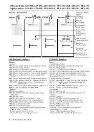
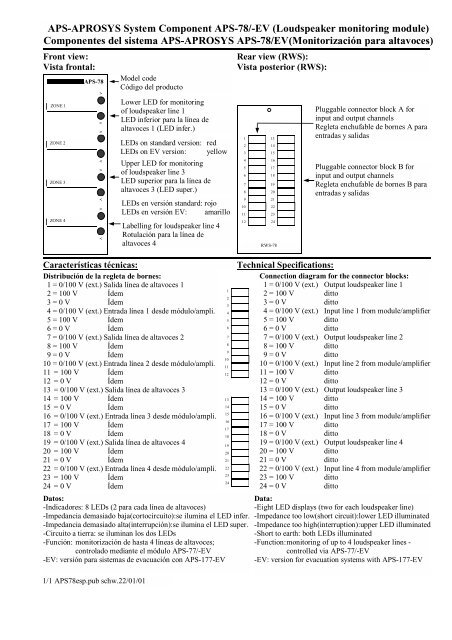
<strong>APS</strong>-<strong>APROSYS</strong> <strong>System</strong> Component <strong>APS</strong>-<strong>78</strong>/-<strong>EV</strong> (Loudspeaker monitoring module)<br />
Componentes del sistema <strong>APS</strong>-<strong>APROSYS</strong> <strong>APS</strong>-<strong>78</strong>/<strong>EV</strong>(Monitorización para altavoces)<br />
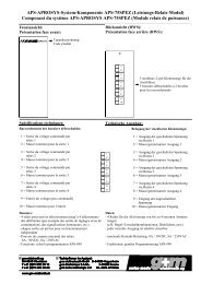
Front view:<br />
Vista frontal:<br />
ZONE 1<br />
ZONE 2<br />
ZONE 3<br />
ZONE 4<br />
<strong>APS</strong>-<strong>78</strong><br />
Datos:<br />
-Indicadores: 8 LEDs (2 para cada línea de altavoces)<br />
-Impedancia demasiado baja(cortocircuito):se ilumina el LED infer.<br />
-Impedancia demasiado alta(interrupción):se ilumina el LED super.<br />
-Circuito a tierra: se iluminan los dos LEDs<br />
-Función: monitorización de hasta 4 líneas de altavoces;<br />
controlado mediante el módulo <strong>APS</strong>-77/-<strong>EV</strong><br />
-<strong>EV</strong>: versión para sistemas de evacuación con <strong>APS</strong>-177-<strong>EV</strong><br />
1/1 <strong>APS</strong><strong>78</strong>esp.pub schw.22/01/01<br />
><br />
<<br />
><br />
<<br />
><br />
<<br />
><br />
<<br />
Model code<br />
Código del producto<br />
Lower LED for monitoring<br />
of loudspeaker line 1<br />
LED inferior para la línea de<br />
altavoces 1 (LED infer.)<br />
LEDs on standard version: red<br />
LEDs on <strong>EV</strong> version: yellow<br />
Upper LED for monitoring<br />
of loudspeaker line 3<br />
LED superior para la línea de<br />
altavoces 3 (LED super.)<br />
LEDs en versión standard: rojo<br />
LEDs en versión <strong>EV</strong>: amarillo<br />
Labelling for loudspeaker line 4<br />
Rotulación para la línea de<br />
altavoces 4<br />
Características técnicas:<br />
Distribución de la regleta de bornes:<br />
1 = 0/100 V (ext.) Salida línea de altavoces 1<br />
2 = 100 V Ídem<br />
3 = 0 V Ídem<br />
4 = 0/100 V (ext.) Entrada línea 1 desde módulo/ampli.<br />
5 = 100 V Ídem<br />
6 = 0 V Ídem<br />
7 = 0/100 V (ext.) Salida línea de altavoces 2<br />
8 = 100 V Ídem<br />
9 = 0 V Ídem<br />
10 = 0/100 V (ext.) Entrada línea 2 desde módulo/ampli.<br />
11 = 100 V Ídem<br />
12 = 0 V Ídem<br />
13 = 0/100 V (ext.) Salida línea de altavoces 3<br />
14 = 100 V Ídem<br />
15 = 0 V Ídem<br />
16 = 0/100 V (ext.) Entrada línea 3 desde módulo/ampli.<br />
17 = 100 V Ídem<br />
18 = 0 V Ídem<br />
19 = 0/100 V (ext.) Salida línea de altavoces 4<br />
20 = 100 V Ídem<br />
21 = 0 V Ídem<br />
22 = 0/100 V (ext.) Entrada línea 4 desde módulo/ampli.<br />
23 = 100 V Ídem<br />
24 = 0 V Ídem<br />
1<br />
2<br />
3<br />
4<br />
5<br />
6<br />
7<br />
8<br />
9<br />
10<br />
11<br />
12<br />
13<br />
14<br />
15<br />
16<br />
17<br />
18<br />
19<br />
20<br />
21<br />
22<br />
23<br />
24<br />
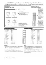
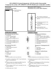
Rear view (RWS):<br />
Vista posterior (RWS):<br />
1<br />
2<br />
3<br />
4<br />
5<br />
6<br />
7<br />
8<br />
9<br />
10<br />
11<br />
12<br />
13<br />
14<br />
15<br />
16<br />
17<br />
18<br />
19<br />
20<br />
21<br />
22<br />
23<br />
24<br />
RWS-<strong>78</strong><br />
Pluggable connector block A for<br />
input and output channels<br />
Regleta enchufable de bornes A para<br />
entradas y salidas<br />
Pluggable connector block B for<br />
input and output channels<br />
Regleta enchufable de bornes B para<br />
entradas y salidas<br />
Technical Specifications:<br />
Connection di<strong>ag</strong>ram for the connector blocks:<br />
1 = 0/100 V (ext.) Output loudspeaker line 1<br />
2 = 100 V ditto<br />
3 = 0 V ditto<br />
4 = 0/100 V (ext.) Input line 1 from module/amplifier<br />
5 = 100 V ditto<br />
6 = 0 V ditto<br />
7 = 0/100 V (ext.) Output loudspeaker line 2<br />
8 = 100 V ditto<br />
9 = 0 V ditto<br />
10 = 0/100 V (ext.) Input line 2 from module/amplifier<br />
11 = 100 V ditto<br />
12 = 0 V ditto<br />
13 = 0/100 V (ext.) Output loudspeaker line 3<br />
14 = 100 V ditto<br />
15 = 0 V ditto<br />
16 = 0/100 V (ext.) Input line 3 from module/amplifier<br />
17 = 100 V ditto<br />
18 = 0 V ditto<br />
19 = 0/100 V (ext.) Output loudspeaker line 4<br />
20 = 100 V ditto<br />
21 = 0 V ditto<br />
22 = 0/100 V (ext.) Input line 4 from module/amplifier<br />
23 = 100 V ditto<br />
24 = 0 V ditto<br />
Data:<br />
-Eight LED displays (two for each loudspeaker line)<br />
-Impedance too low(short circuit):lower LED illuminated<br />
-Impedance too high(interruption):upper LED illuminated<br />
-Short to earth: both LEDs illuminated<br />
-Function: monitoring of up to 4 loudspeaker lines -<br />
controlled via <strong>APS</strong>-77/-<strong>EV</strong><br />
-<strong>EV</strong>: version for evacuation systems with <strong>APS</strong>-177-<strong>EV</strong>