STEFANY Forno / SVEZIA New / NORVEGIA New
STEFANY Forno / SVEZIA New / NORVEGIA New
STEFANY Forno / SVEZIA New / NORVEGIA New

You also want an ePaper? Increase the reach of your titles
YUMPU automatically turns print PDFs into web optimized ePapers that Google loves.
ISTRUZIONI PER L’INSTALLAZIONE, L’USO E LA MANUTENZIONE – IT<br />
INSTRUCTIONS FOR INSTALLATION, USE AND MAINTENANCE - EN<br />
ANWEISUNGEN FÜR DIE AUFSTELLUNG, DEN GEBRAUCH UND DIE WARTUNG - DE<br />
STUFA CAMINO / CHIMNEY STOVE / KAMINOFEN<br />
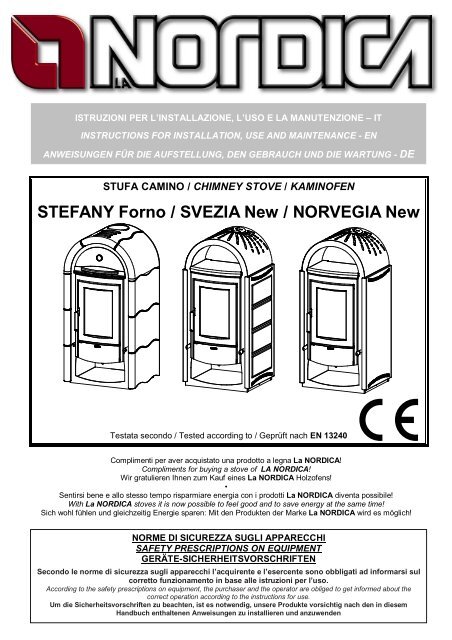
<strong>STEFANY</strong> <strong>Forno</strong> / <strong>SVEZIA</strong> <strong>New</strong> / <strong>NORVEGIA</strong> <strong>New</strong><br />
Testata secondo / Tested according to / Geprüft nach EN 13240<br />
Complimenti per aver acquistato una prodotto a legna La NORDICA!<br />
Compliments for buying a stove of LA NORDICA!<br />
Wir gratulieren Ihnen zum Kauf eines La NORDICA Holzofens!<br />
•<br />
Sentirsi bene e allo stesso tempo risparmiare energia con i prodotti La NORDICA diventa possibile!<br />
With La NORDICA stoves it is now possible to feel good and to save energy at the same time!<br />
Sich wohl fühlen und gleichzeitig Energie sparen: Mit den Produkten der Marke La NORDICA wird es möglich!<br />
NORME DI SICUREZZA SUGLI APPARECCHI<br />
SAFETY PRESCRIPTIONS ON EQUIPMENT<br />
GERÄTE-SICHERHEITSVORSCHRIFTEN<br />
|<br />
Secondo le norme di sicurezza sugli apparecchi l’acquirente e l’esercente sono obbligati ad informarsi sul<br />
corretto funzionamento in base alle istruzioni per l’uso.<br />
According to the safety prescriptions on equipment, the purchaser and the operator are obliged to get informed about the<br />
correct operation according to the instructions for use.<br />
Um die Sicherheitsvorschriften zu beachten, ist es notwendig, unsere Produkte vorsichtig nach den in diesem<br />
Handbuch enthaltenen Anweisungen zu installieren und anzuwenden
Stufa camino / Chimney stove / Kaminofen <strong>STEFANY</strong> <strong>Forno</strong> / <strong>SVEZIA</strong> <strong>New</strong> / <strong>NORVEGIA</strong> <strong>New</strong><br />
2 Istruzioni uso e manutenzione / Instructions for installation / Aufstell- und Bedienungsanleitung – IT– EN – DE – Rev.02
Stufa camino / Chimney stove / Kaminofen <strong>STEFANY</strong> <strong>Forno</strong> / <strong>SVEZIA</strong> <strong>New</strong> / <strong>NORVEGIA</strong> <strong>New</strong><br />
DICHIARAZIONE DI CONFORMITA’ DEL COSTRUTTORE<br />
Oggetto: assenza di amianto e cadmio<br />
Si dichiara che tutti i nostri apparecchi vengono assemblati con materiali che non presentano parti di<br />
amianto o suoi derivati e che nel materiale d’apporto utilizzato per le saldature non è presente/utilizzato in<br />
nessuna forma il cadmio, come previsto dalla norma di riferimento.<br />
Oggetto: Regolamento CE n. 1935/2004<br />
Si dichiara che in tutti gli apparecchi da noi prodotti, i materiali destinati a venire a contatto con i cibi sono<br />
adatti all’uso alimentari, in conformità al Regolamento CE in oggetto.<br />
DECLARATION OF CONFORMITY OF THE MANUFACTURER<br />
Object: Absence of asbestos and cadmium<br />
We declare that the materials used for the assembly of all our appliances are without asbestos parts or asbestos derivates and<br />
that in the material used for welding, cadmium is not present, as prescribed in relevant norm.<br />
Object: CE n. 1935/2004 regulation.<br />
We declare that in all products we produce, the materials which will get in touch with food are suitable for<br />
alimentary use, according to the a.m. CE regulation.<br />
KONFORMITÄTSERKLÄRUNG DES HERSTELLERS<br />
Betreff: Fehlen von Asbest und Kadmium<br />
Wir bestätigen, dass die verwendeten Materialen oder Teilen für die Herstellung der La Nordica Geräte<br />
ohne Asbest und Derivat sind und auch das Lot für das Schweißen immer ohne Kadmium ist.<br />
Betreff: Ordnung CE n. 1935/2004. Wir erklären in alleiniger Verantwortung, dass die Materialien der<br />
Teile, die für den Kontakt mit Lebensmitteln vorgesehen sind, für die Nahrungsbenutzung geeignet sind<br />
und der Richtlinien CE n. 1935/2004 erfüllen.<br />
Istruzioni uso e manutenzione / Instructions for installation / Aufstell- und Bedienungsanleitung – IT – EN – DE – Rev.02 3
Stufa camino / Chimney stove / Kaminofen <strong>STEFANY</strong> <strong>Forno</strong> / <strong>SVEZIA</strong> <strong>New</strong> / <strong>NORVEGIA</strong> <strong>New</strong><br />
INDICE IT<br />
ISTRUZIONI PER IL MONTAGGIO DELLE PIASTRELLE MODELLO <strong>STEFANY</strong> FORNO Maiolica....................................... 6<br />
ISTRUZIONI PER IL MONTAGGIO DELLE PIASTRELLE MODELLO <strong>STEFANY</strong> FORNO Petra........................................... 8<br />
1. DATI TECNICI.................................................................................................................................................................... 9<br />
2. DESCRIZIONE TECNICA................................................................................................................................................. 10<br />
3. NORME PER L’INSTALLAZIONE ..................................................................................................................................... 10<br />
4. SICUREZZA ANTINCENDIO ............................................................................................................................................ 11<br />
4.1. PRONTO INTERVENTO .......................................................................................................................................... 12<br />
5. CANNA FUMARIA............................................................................................................................................................ 12<br />
5.1. POSIZIONE DEL COMIGNOLO................................................................................................................................ 13<br />
6. COLLEGAMENTO AL CAMINO ........................................................................................................................................ 15<br />
7. AFFLUSSO D’ARIA NEL LUOGO D’INSTALLAZIONE DURANTE LA COMBUSTIONE...................................................... 15<br />
8. COMBUSTIBILI AMMESSI / NON AMMESSI .................................................................................................................... 16<br />
9. ACCENSIONE.................................................................................................................................................................. 17<br />
10. FUNZIONAMENTO NORMALE .................................................................................................................................... 18<br />
11. FUNZIONAMENTO NEI PERIODI DI TRANSIZIONE .................................................................................................... 18<br />
12. USO DEL FORNO (<strong>STEFANY</strong> <strong>Forno</strong>)........................................................................................................................... 19<br />
12.1. SCALDAVIVANDE (Svezia – Norvegia) .................................................................................................................... 19<br />
13. MANUTENZIONE E CURA........................................................................................................................................... 19<br />
13.1. PULIZIA CANNA FUMARIA...................................................................................................................................... 19<br />
13.2. PULIZIA VETRO ...................................................................................................................................................... 19<br />
13.3. PULIZIA GRIGLIA FOCOLARE................................................................................................................................. 19<br />
13.4. PULIZIA CASSETTO CENERE................................................................................................................................. 20<br />
13.5. LE MAIOLICHE........................................................................................................................................................ 20<br />
14. FERMO ESTIVO .......................................................................................................................................................... 20<br />
15. COLLEGAMENTO ALLA CANNA FUMARIA DI UN CAMINETTO O FOCOLARE APERTO............................................ 21<br />
16. POSIZIONE DEFLETTORE FUMI / POSITION OF THE SMOKE DEFLECTOR / STELLUNG DER<br />
RAUCHUMLENKPLATTE ......................................................................................................................................................... 47<br />
17. SCHEDA TECNICA / TECHNICAL DATA SHEETS / TECHNISCHE PROTOKOLLE...................................................... 48<br />
INDEX EN<br />
INSTRUCTIONS FOR ASSEMBLY OF TILES <strong>STEFANY</strong> FORNO MODEL <strong>STEFANY</strong> FORNO Majolika............................... 6<br />
INSTRUCTIONS FOR ASSEMBLY OF TILES <strong>STEFANY</strong> FORNO MODEL <strong>STEFANY</strong> FORNO Soapstone........................... 8<br />
1. TECHNICAL DATA........................................................................................................................................................... 22<br />
2. TECHNICAL DESCRIPTION............................................................................................................................................. 23<br />
3. RULES FOR INSTALLATION ........................................................................................................................................... 23<br />
4. FIRE SAFETY .................................................................................................................................................................. 24<br />
4.1. FIRST-AID MEASURES ........................................................................................................................................... 24<br />
5. FLUE ............................................................................................................................................................................... 25<br />
5.1. CHIMNEY CAP ........................................................................................................................................................ 25<br />
6. CONNECTION TO THE CHIMNEY ................................................................................................................................... 27<br />
7. AIR ENTRANCE INTO THE INSTALLATION PLACE DURING THE COMBUSTION .......................................................... 28<br />
8. ADMITTED/NOT ADMITTED FUEL................................................................................................................................... 28<br />
9. LIGHTING ........................................................................................................................................................................ 29<br />
10. NORMAL OPERATION ................................................................................................................................................ 30<br />
11. OPERATION DURING TRANSITION PERIODS............................................................................................................ 31<br />
12. OVEN OPERATION (if present) .................................................................................................................................... 31<br />
12.1. FOOD WARMER OPERATION................................................................................................................................. 31<br />
13. MAINTENANCE AND CARE......................................................................................................................................... 31<br />
13.1. CLEANING OF THE FLUE ....................................................................................................................................... 31<br />
13.2. CLEANING OF THE GLASS..................................................................................................................................... 31<br />
13.3. CLEANING OF THE HEARTH GRATE ..................................................................................................................... 32<br />
13.4. CLEANING OF THE ASH DRAWER......................................................................................................................... 32<br />
13.5. MAJOLICAS............................................................................................................................................................. 32<br />
14. SUMMER STOP........................................................................................................................................................... 32<br />
15. CONNECTING A CHIMNEY OR OPEN FURNACE TO THE FLUE................................................................................ 33<br />
16. POSIZIONE DEFLETTORE FUMI / POSITION OF THE SMOKE DEFLECTOR / STELLUNG DER<br />
RAUCHUMLENKPLATTE ......................................................................................................................................................... 47<br />
17. SCHEDA TECNICA / TECHNICAL DATA SHEETS / TECHNISCHE PROTOKOLLE...................................................... 48<br />
4 Istruzioni uso e manutenzione / Instructions for installation / Aufstell- und Bedienungsanleitung – IT– EN – DE – Rev.02
Stufa camino / Chimney stove / Kaminofen <strong>STEFANY</strong> <strong>Forno</strong> / <strong>SVEZIA</strong> <strong>New</strong> / <strong>NORVEGIA</strong> <strong>New</strong><br />
INHALTSVERZEICHNIS DE<br />
MONTAGEANLEITUNG DER KERAMIK IM MODELL <strong>STEFANY</strong> FORNO Majolika.............................................................. 6<br />
MONTAGEANLEITUNG DER KERAMIK IM MODELL <strong>STEFANY</strong> FORNO Speckstein.......................................................... 8<br />
1. TECHNISCHE DATEN...................................................................................................................................................... 34<br />
2. TECHNISCHE BESCHREIBUNG...................................................................................................................................... 35<br />
3. AUFSTELLHINWEISE...................................................................................................................................................... 35<br />
4. BRANDSCHUTZ .............................................................................................................................................................. 36<br />
4.1. NOTFALLMASSNAHMEN ........................................................................................................................................ 37<br />
5. SCHORNSTEINROHR ..................................................................................................................................................... 37<br />
5.1. SCHORNSTEIN....................................................................................................................................................... 38<br />
6. KAMINANSCHLUSS......................................................................................................................................................... 40<br />
7. LUFTZUFLUSS AM AUFSTELLORT WÄHREND DER VERBRENNUNG .......................................................................... 40<br />
8. ZULÄSSIGE/UNZULÄSSIGE BRENNSTOFFE.................................................................................................................. 41<br />
9. ANFEUERUNG ................................................................................................................................................................ 42<br />
10. NORMALBETRIEB....................................................................................................................................................... 43<br />
11. BETRIEB IN DER ÜBERGANGSZEIT........................................................................................................................... 43<br />
12. BACKEN (wenn anwesend) .......................................................................................................................................... 44<br />
12.1. TELLERWÄRMERFACH .......................................................................................................................................... 44<br />
13. WARTUNG UND PFLEGE............................................................................................................................................ 44<br />
13.1. REINIGUNG DES SCHORNSTEINS......................................................................................................................... 44<br />
13.2. REINIGUNG DES SICHTFENSTERS ....................................................................................................................... 44<br />
13.3. REINIGUNG DES FEUERROSTES.......................................................................................................................... 44<br />
13.4. REINIGUNG DES ASCHEKASTENS........................................................................................................................ 45<br />
13.5. DIE KACHELN ......................................................................................................................................................... 45<br />
14. SOMMERPAUSE ......................................................................................................................................................... 45<br />
15. ANSCHLUSS AN DEN RAUCHABZUG EINES OFFENEN KAMINS .............................................................................. 45<br />
16. POSIZIONE DEFLETTORE FUMI / POSITION OF THE SMOKE DEFLECTOR / STELLUNG DER<br />
RAUCHUMLENKPLATTE ......................................................................................................................................................... 47<br />
17. SCHEDA TECNICA / TECHNICAL DATA SHEETS / TECHNISCHE PROTOKOLLE...................................................... 48<br />
Istruzioni uso e manutenzione / Instructions for installation / Aufstell- und Bedienungsanleitung – IT – EN – DE – Rev.02 5
Stufa camino / Chimney stove / Kaminofen <strong>STEFANY</strong> <strong>Forno</strong> / <strong>SVEZIA</strong> <strong>New</strong> / <strong>NORVEGIA</strong> <strong>New</strong><br />
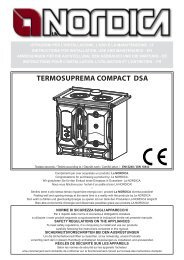
ISTRUZIONI PER IL MONTAGGIO DELLE PIASTRELLE MODELLO <strong>STEFANY</strong> FORNO Maiolica<br />
Le piastrelle della stufa <strong>STEFANY</strong> FORNO vanno posizionate come da Figura 1: si posiziona per prima<br />
una delle piastrelle piane (A) sui due sostegni più in basso Figura 2 e Figura 3) assicurandosi che gli<br />
appoggi della piastrella siano ben agganciati ai sostegni. Si procede allo stesso modo con la seconda<br />
piastrella piana (A), che va agganciata al terzo e al quarto sostegno a partire dal basso (Figura 3). Si<br />
procede, quindi, con la terza piastrella piana e successivamente una delle due piastrelle curve senza foro<br />
(B). Per bloccare quest’ultima, e necessario montare l’apposita squadretta, che va fissata all’interno della<br />
schiena della stufa (Figura 4). Si ripetono le stesse operazioni per montare le piastrelle (A-B) sull’altro lato<br />
della stufa. Infine, si posiziona la piastrella curva con il foro (C).<br />
INSTRUCTIONS FOR ASSEMBLY OF TILES <strong>STEFANY</strong> FORNO MODEL <strong>STEFANY</strong> FORNO Majolika<br />
The tiles of <strong>STEFANY</strong> FORNO stove must be positioned as in Picture 1: first position one of the flat tiles<br />
(A) on the two lowest supports (Picture 2 and Picture 3); make sure the supports of the tile are well hooked<br />
to the holders.<br />
Proceed in the same way with the second flat tile (A) which must be hooked to the third and fourth holder,<br />
starting from the bottom (Picture 3). Position then the third flat tile and then one of the two curved tiles<br />
without a hole (B). To block this last tile it is necessary to mount the suitable bracket, which must be fixed<br />
inside the back of the stove (Picture 4).Repeat the same operations to mount the tiles (A-B) on the other<br />
side of the stove. Finally, position the curved tile with the hole (C).<br />
MONTAGEANLEITUNG DER KERAMIK IM MODELL <strong>STEFANY</strong> FORNO Majolika<br />
Die Keramik für das Modell <strong>STEFANY</strong> <strong>Forno</strong> sind nach ABB. 1 der numerierten Reihenfolge (nach<br />
Nummern auf der Rückseite der Kachel) zu sortieren.<br />
Es ist darauf zu achten immer mit einer flachen Keramik (A) anzufangen und diese fest mit der Auflage in<br />
der Unterstützung anzubringen. Siehe ABB. 2 und ABB. 3.<br />
Die halbrunde Keramik (B) muß an der Ofenrückseite mittels der mitgelieferten Schraube und Blechmutter<br />
gegen herabfallen gesichert werden. Siehe ABB. 4.<br />
Zum Schluß wird Keramik (C) auf die Ofenoberseite aufgelegt.<br />
6 Istruzioni uso e manutenzione / Instructions for installation / Aufstell- und Bedienungsanleitung – IT– EN – DE – Rev.02
Stufa camino / Chimney stove / Kaminofen <strong>STEFANY</strong> <strong>Forno</strong> / <strong>SVEZIA</strong> <strong>New</strong> / <strong>NORVEGIA</strong> <strong>New</strong><br />
<strong>STEFANY</strong> FORNO Maiolica<br />
Figura 1<br />
Picture 1<br />
ABB. 1<br />
RIPARO ZINCATO<br />
ZINC SHEET<br />
VERZINKTENBLECH<br />
SQUADRETTA<br />
LITTLE SQUARE<br />
BEFESTIGUNGSWINKEL<br />
Figura 3<br />
Picture 3<br />
ABB. 3<br />
VITE<br />
SCREEW<br />
VERZINKTENBLECH<br />
C<br />
Istruzioni uso e manutenzione / Instructions for installation / Aufstell- und Bedienungsanleitung – IT – EN – DE – Rev.02 7<br />
B<br />
A<br />
A<br />
A<br />
SOSTEGNO<br />
COUPLING<br />
ZUHAKEN<br />
Figura 4<br />
Picture 4<br />
ABB. 4<br />
APPOGGIO<br />
SUPPORT<br />
STÜTZE<br />
Figura 2<br />
Picture 2<br />
ABB. 2
Stufa camino / Chimney stove / Kaminofen <strong>STEFANY</strong> <strong>Forno</strong> / <strong>SVEZIA</strong> <strong>New</strong> / <strong>NORVEGIA</strong> <strong>New</strong><br />
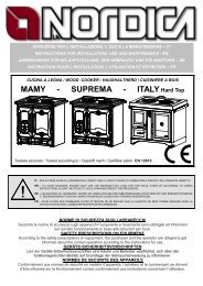
ISTRUZIONI PER IL MONTAGGIO DELLE PIASTRELLE MODELLO <strong>STEFANY</strong> FORNO Petra<br />
INSTRUCTIONS FOR ASSEMBLY OF TILES <strong>STEFANY</strong> FORNO MODEL <strong>STEFANY</strong> FORNO Soapstone<br />
MONTAGEANLEITUNG DER KERAMIK IM MODELL <strong>STEFANY</strong> FORNO Speckstein<br />
8 Istruzioni uso e manutenzione / Instructions for installation / Aufstell- und Bedienungsanleitung – IT– EN – DE – Rev.02
Stufa camino <strong>STEFANY</strong> <strong>Forno</strong> / <strong>SVEZIA</strong> <strong>New</strong> / <strong>NORVEGIA</strong> <strong>New</strong><br />
Definizione : Stufa camino secondo<br />
EN 13240<br />
1. DATI TECNICI<br />
<strong>STEFANY</strong><br />
FORNO<br />
La capacità di riscaldamento dei locali secondo EN 13240, per edifici il cui isolamento termico non<br />
corrisponde ai requisiti del Regolamento sugli isolamenti termici, è :<br />
(30 Kcal/h x m 3 ) - tipo di costruzione favorevole: 258 m³<br />
(40 Kcal/h x m 3 ) - tipo di costruzione meno favorevole: 193 m³<br />
(50 Kcal/h x m 3 ) - tipo di costruzione sfavorevole: 155 m³<br />
<strong>SVEZIA</strong><br />
NEW<br />
<strong>NORVEGIA</strong><br />
NEW<br />
Sistema costruttivo 1 1 1<br />
Potenza nominale in kW 9 9 9<br />
Rendimento in % 84.5 84.5 84.5<br />
Diametro tubo in mm 150 150 150<br />
Quantità max di combustibile- legna in kg 2.5 2.5 2.5<br />
CO misurato al 13% di ossigeno in % 0.07 0.07 0.07<br />
Emissione gas di scarico in g/s- legna 7.8 7.8 7.8<br />
Temperatura gas allo scarico in °C - legna 206 206 206<br />
Depressione a rendimento calorifico nominale in mm H2O legna 1,2 1,2 1,2<br />
Dimensioni apertura focolare in mm (LxH) 300x340 300x310 300x310<br />
Dimensioni corpo focolare / piano focolare in mm (LxHxP) 377x340x388 377x340x385 377x340x385<br />
Dimensioni forno in mm (LxHxP) 417x210x275 / /<br />
Tipo di griglia Griglia piana, girevole dall’esterno<br />
Altezza in mm 1300 1254 1254<br />
Larghezza in mm 660 607 599<br />
Profondità (senza maniglie) in mm 586 554 554<br />
Peso in Kg 230 186 181<br />
Distanze di sicurezza antincendio Capitolo 4<br />
Con un isolamento termico adeguato alle disposizioni sulla protezione del calore il volume di riscaldamento<br />
è maggiore.<br />
Con un riscaldamento temporaneo, in caso di interruzioni superiori a 8h, la capacità di riscaldamento<br />
diminuisce del 25% circa.<br />
Istruzioni per l’installazione, l’uso e la manutenzione – IT – Rev.02 9
2. DESCRIZIONE TECNICA<br />
Stufa camino <strong>STEFANY</strong> <strong>Forno</strong> / <strong>SVEZIA</strong> <strong>New</strong> / <strong>NORVEGIA</strong> <strong>New</strong><br />
Le stufe a legna de La NORDICA si addicono a riscaldare spazi abitativi per alcuni periodi. Come<br />
combustibili vengono utilizzati ceppi di legna.<br />
La stufa-camino è costituita di lastre in lamiera d’acciaio verniciata, ghisa smaltata e ceramica<br />
termoradiante. Il focolare è internamente rivestito di singole lastre in refrattario.<br />
Al suo interno si trova un portagriglia e una griglia piana in ghisa di grosso spessore facilmente estraibili.<br />
Il focolare è dotato di una porta panoramica con vetro ceramico (resistente fino a 700°C). Questo cons ente<br />
un’affascinante vista sulle fiamme ardenti. Inoltre viene così impedita ogni possibile fuoriuscita di scintille e<br />
fumo<br />
Il deflettore interno in vermiculite riflette l’irradiazione del fuoco ed aumenta ulteriormente la temperatura<br />
all’interno della camera di combustione. In questo modo, sfruttando i flussi dei gas di scarico, si ottimizza la<br />
combustione e si aumenta il grado di efficienza. (Pag.47)<br />
Sotto la porta del focolare si trova un cassetto cenere estraibile con relativa porta di chiusura.<br />
Il riscaldamento dell’ambiente avviene:<br />
a) per convezione (circa 70%): il passaggio dell’aria attraverso il doppio mantello della stufa rilascia calore<br />
nell’ambiente<br />
b) per radiazione: attraverso il vetro panoramico e le superfici esterne calde della stufa viene irraggiato<br />
calore nell’ambiente.<br />
La stufa è fornita di un registro per l’aria primaria (Figura 5 pos.A) ed uno per quella secondaria (Figura 5<br />
pos.B), con i quali viene regolata l’aria di combustione.<br />
Registro ARIA PRIMARIA (laterale dx)<br />
Sotto la porta del focolare si trova la leva di comando del registro per<br />
l’aria primaria (Figura 5 pos.A). Con questo registro viene regolato il<br />
passaggio dell’aria che entra nella parte bassa della stufa ed<br />
attraverso opportuni canali viene convogliato in direzione del<br />
combustibile. L’aria primaria è necessaria per il processo di<br />
combustione in fase di accensione. Il cassetto cenere deve essere<br />
svuotato regolarmente in modo che la cenere non possa ostacolare<br />
l’entrata dell’aria primaria.<br />
Per APRIRE il passaggio dell’aria PRIMARIA bisogna tirare il<br />
registro (fare uscire il registro dalla stufa).<br />
Il registro dell’aria primaria deve essere aperto appena un po’ durante<br />
la combustione di legna, poiché altrimenti la legna arde troppo<br />
velocemente e la stufa si può surriscaldare. Il registro è aperto quando<br />
è totalmente estratto.<br />
(vedi paragrafo 10).<br />
Registro ARIA SECONDARIA (laterale sx)<br />
A sinistra della porta del focolare si trova il registro dell’aria secondaria (Figura 5 pos.B). Questo deve<br />
essere aperto (quindi tutto inserito) in particolare per la combustione di legna cosicché il carbonio<br />
incombusto può subire una post-combustione (vedi paragrafo 10).<br />
3. NORME PER L’INSTALLAZIONE<br />
Figura 5<br />
La stufa è assemblata e pronta per l’allacciamento e deve essere collegata mediante un raccordo<br />
all’esistente canna fumaria della casa. Il raccordo deve essere possibilmente corto, rettilineo, orizzontale o<br />
posizionato leggermente in salita. I collegamenti devono essere a tenuta stagna. E’ obbligatorio<br />
rispettare norme nazionali ed europee, disposizioni locali o in materia di legislazione edilizia,<br />
nonché regolamentazioni antincendio. Pertanto vi consigliamo di informarvi preventivamente presso il<br />
Vs. capo spazzacamino distrettuale.<br />
10 Istruzioni per l’installazione, l’uso e la manutenzione – IT – Rev.02<br />
B<br />
A
Stufa camino <strong>STEFANY</strong> <strong>Forno</strong> / <strong>SVEZIA</strong> <strong>New</strong> / <strong>NORVEGIA</strong> <strong>New</strong><br />
Bisogna inoltre verificare il sufficiente afflusso d’aria necessario alla combustione, a tale proposito è<br />
fondamentale prestare attenzione a finestre e porte con chiusura stagna (guarnizioni di tenuta).<br />
Non è consentito il collegamento di più apparecchi allo stesso camino. Il diametro dell’apertura della canna<br />
fumaria per il collegamento deve corrispondere per lo meno al diametro del tubo fumo.<br />
L’apertura dovrebbe essere dotata di una connessione a muro per la ricezione del tubo di scarico e di un<br />
rosone. Prima dell’installazione verificare se la portata della sottostruttura regge il peso del vostro<br />
apparecchio. In caso di portata insufficiente è necessario adottare opportune misure (ad es. piastra per la<br />
distribuzione del peso) per raggiungere la stessa.<br />
La Nordica S.p.a. non è responsabile del prodotto modificato senza autorizzazione e tanto meno<br />
per l’uso di ricambi non originali.<br />
I FOCOLARI NON SI DEVONO MODIFICARE.<br />
4. SICUREZZA ANTINCENDIO<br />
Figura 6 Nell’installazione della stufa devono essere osservate le seguenti misure di sicurezza:<br />
a) la distanza minima da elementi costruttivi ed oggetti infiammabili e sensibili al calore (mobili,<br />
rivestimenti di legno, stoffe ecc.) deve essere di 20cm dal retro e da entrambi i lati; al fine di assicurare<br />
un sufficiente isolamento termico (vedi Figura 6 A).<br />
b) davanti alla porta del focolare, nell’area di radiazione della stessa non deve esserci alcun oggetto o<br />
materiale di costruzione infiammabile e sensibile al calore a meno di 100cm di distanza. Tale distanza<br />
può essere ridotta a 40cm qualora venga installata una protezione, retroventilata e resistente al calore,<br />
davanti all’intero componente da proteggere. Tutte le distanze minime di sicurezza sono indicate<br />
sulla targhetta del prodotto e non si deve scendere al di sotto delle stesse<br />
c) qualora la stufa venga installata su un pavimento di materiale infiammabile, bisogna prevedere un<br />
sottofondo ignifugo, per esempio una pedana d'acciaio (dimensioni secondo l’ordinamento regionale). Il<br />
sottofondo deve sporgere frontalmente di almeno 50cm e lateralmente di almeno 30cm oltre<br />
all’apertura della porta di carico.(vedi Figura 6 B).<br />
A B<br />
Figura 6<br />
Istruzioni per l’installazione, l’uso e la manutenzione – IT – Rev.02 11
Stufa camino <strong>STEFANY</strong> <strong>Forno</strong> / <strong>SVEZIA</strong> <strong>New</strong> / <strong>NORVEGIA</strong> <strong>New</strong><br />
La stufa deve funzionare esclusivamente con il cassetto cenere inserito. I residui solidi della combustione<br />
(ceneri) devono essere raccolti in un contenitore ermetico e resistente al fuoco. La stufa non deve mai<br />
essere accesa in presenza di emissioni gassose o vapori (per esempio colla per linoleum, benzina ecc.).<br />
Non depositate materiali infiammabili nelle vicinanze della stufa.<br />
Durante la combustione viene sprigionata energia termica che comporta un marcato riscaldamento delle<br />
superfici, della porta e del vetro del focolare, delle maniglie delle porte o di comando, del tubo fumi ed<br />
eventualmente della parte anteriore dell’apparecchio. Evitate il contatto con tali elementi senza un<br />
corrispondente abbigliamento protettivo o senza utensili accessori (guanti resistenti al calore, dispositivi di<br />
comando).<br />
Fate in modo che i bambini siano consapevoli di questi pericoli e teneteli lontani dal focolare<br />
durante il suo funzionamento .<br />
Quando si utilizza un combustibile errato o troppo umido si potrebbero formare dei depositi (creosoto) nella<br />
canna fumaria con possibile incendio della canna fumaria stessa.<br />
4.1. PRONTO INTERVENTO<br />
Se si manifesta un incendio nel collegamento o nella canna fumaria :<br />
a) Chiudere la porta di caricamento e del cassetto cenere.<br />
b) Chiudere i registri dell’aria comburente<br />
c) Spegnere tramite l’uso di estintori ad anidride carbonica ( CO2 a polveri )<br />
d) Richiedere l’immediato intervento dei Vigili del Fuoco<br />
Non spegnere il fuoco con l’uso di getti d’acqua.<br />
Quando la canna fumaria smette di bruciare, farla verificare da uno specialista per individuare eventuali<br />
crepe o punti permeabili.<br />
5. CANNA FUMARIA<br />
Requisiti fondamentali per un corretto funzionamento<br />
dell’apparecchio:<br />
• la sezione interna deve essere preferibilmente<br />
circolare;<br />
• essere termicamente isolata ed impermeabile e<br />
costruita con materiali idonei a resistere al calore,<br />
ai prodotti della combustione ed alle eventuali<br />
condense;<br />
• essere priva di strozzature ed avere andamento<br />
verticale con deviazioni non superiori a 45°;<br />
• se già usata deve essere pulita;<br />
• rispettare i dati tecnici del manuale di istruzioni;<br />
Qualora le canne fumarie fossero a sezione quadrata o<br />
rettangolare gli spigoli interni devono essere arrotondati<br />
con raggio non inferiore a 20 mm. Per la sezione<br />
rettangolare il rapporto massimo tra i lati deve essere ≤<br />
1,5.<br />
Una sezione troppo piccola provoca una diminuzione del<br />
tiraggio. Si consiglia un’altezza minima di 4 m.<br />
Sono vietate e pertanto pregiudicano il buon<br />
funzionamento dell’apparecchio: fibrocemento, acciaio<br />
zincato, superfici interne ruvide e porose. In Fig. 7 sono<br />
riportati alcuni esempi di soluzione.<br />
La sezione minima deve essere di 4 dm 2 (per esempio<br />
(1) (2)<br />
(1) Canna fumaria in acciaio AISI 316 con doppia<br />
camera isolata con materiale resistente a<br />
400°C. Efficienza 100% ottima.<br />
(2) Canna fumaria in refrattario con doppia<br />
camera isolata e rivestimento esterno in<br />
calcestruzzo alleggerito. Efficienza 100%<br />
ottima.<br />
(3) Canna fumaria tradizionale in argilla sezione<br />
quadrata con intercapedini. Efficienza 80%<br />
ottima.<br />
(4) Evitare canne fumarie con sezione<br />
rettangolare interna il cui rapporto sia diverso<br />
dal disegno.<br />
Efficienza 40% mediocre.<br />
Fig. 7<br />
12 Istruzioni per l’installazione, l’uso e la manutenzione – IT – Rev.02<br />
(3)<br />
(4)<br />
Max.<br />
A+1/2A<br />
A+1/2A<br />
A
Stufa camino <strong>STEFANY</strong> <strong>Forno</strong> / <strong>SVEZIA</strong> <strong>New</strong> / <strong>NORVEGIA</strong> <strong>New</strong><br />
20x20cm) per gli apparecchi il cui diametro di condotto è inferiore a 200mm, o 6,25dm 2 (per<br />
esempio 25x25cm) per gli apparecchi con diametro superiore a 200mm.<br />
Il tiraggio creato dalla vostra canna fumaria deve essere sufficiente ma non eccessivo.<br />
Una sezione della canna fumaria troppo importante può presentare un volume troppo grande da riscaldare<br />
e dunque provocare delle difficoltà di funzionamento dell’apparecchio; per evitare ciò provvedete ad<br />
intubare la stessa per tutta la sua altezza. Una sezione troppo piccola provoca una diminuzione del<br />
tiraggio.<br />
La canna fumaria deve essere adeguatamente distanziata da materiali infiammabili o combustibili<br />
mediante un opportuno isolamento o un’intercapedine d’aria.<br />
E’ vietato far transitare all’interno della stessa tubazioni di impianti o canali di adduzione d’aria. E’ proibito<br />
inoltre praticare aperture mobili o fisse, sulla stessa, per il collegamento di ulteriori apparecchi diversi.<br />
5.1. POSIZIONE DEL COMIGNOLO<br />
Il tiraggio della canna fumaria dipende anche dall’idoneità del comignolo.<br />
È pertanto indispensabile che, se costruito artigianalmente, la sezione di uscita sia più di due volte la<br />
sezione interna della canna fumaria.<br />
Dovendo sempre superare il colmo del tetto, il comignolo dovrà assicurare lo scarico anche in presenza di<br />
vento (Fig. 8).<br />
(1) Comignolo industriale<br />
ad elementi prefabbricati,<br />
consente un ottimo<br />
smaltimento dei fumi.<br />
Il comignolo deve rispondere ai seguenti requisiti:<br />
• avere sezione interna equivalente a quella del camino.<br />
• avere sezione utile d’uscita doppia di quella interna della canna fumaria.<br />
• essere costruito in modo da impedire la penetrazione nella canna fumaria di pioggia, neve e di<br />
qualsiasi corpo estraneo.<br />
• essere facilmente ispezionabile, per eventuali operazioni di manutenzione e pulizia.<br />
50 cm<br />
(2) Comignolo artigianale.<br />
La giusta sezione di uscita<br />
deve essere minimo 2 volte<br />
la sezione interna della<br />
canna fumaria, ideale 2,5<br />
volte.<br />
(3) Comignolo per canna<br />
fumaria in acciaio con<br />
cono interno deflettore<br />
dei fumi.<br />
Istruzioni per l’installazione, l’uso e la manutenzione – IT – Rev.02 13<br />
Fig. 8<br />
(1) In caso di canne fumarie affiancate un<br />
comignolo dovrà sovrastare l’altro d’almeno 50 cm<br />
al fine d’evitare trasferimenti di pressione tra le<br />
canne stesse.<br />
Fig. 9
Stufa camino <strong>STEFANY</strong> <strong>Forno</strong> / <strong>SVEZIA</strong> <strong>New</strong> / <strong>NORVEGIA</strong> <strong>New</strong><br />
Figura 10<br />
Figura 11<br />
COMIGNOLI DISTANZE E POSIZIONAMENTO UNI 10683/98<br />
Inclinazione del tetto Distanza tra il colmo e il camino<br />
Altezza minima del camino (misurata dallo<br />
sbocco)<br />
α A (m) H (m)<br />
15°<br />
30°<br />
45°<br />
60°<br />
2 m 10 m<br />
1<br />
m<br />
H min.<br />
α<br />
>A<br />
(1) Il comignolo non deve avere ostacoli entro i 10m da muri,<br />
falde ed alberi. In caso contrario innalzare lo stesso d’almeno<br />
1 m sopra l’ostacolo.<br />
Il comignolo deve oltrepassare il colmo del tetto d’almeno 1 m.<br />
><br />
_ A<br />
(1)Asse colmo<br />
(2)Tetto<br />
< 1,85 m 0,50 m oltre il colmo<br />
> 1,85 m 1,00 m dal tetto<br />
< 1,50 m 0,50 m oltre il colmo<br />
> 1,50 m 1,30 m dal tetto<br />
< 1,30 m 0,50 m oltre il colmo<br />
> 1,30 m 2,00 m dal tetto<br />
< 1,20 m 0,50 m oltre il colmo<br />
> 1,20 m 2,60 m dal tetto<br />
14 Istruzioni per l’installazione, l’uso e la manutenzione – IT – Rev.02<br />
0,5 m
Stufa camino <strong>STEFANY</strong> <strong>Forno</strong> / <strong>SVEZIA</strong> <strong>New</strong> / <strong>NORVEGIA</strong> <strong>New</strong><br />
6. COLLEGAMENTO AL CAMINO<br />
Gli apparecchi con chiusura automatica della porta (tipo 1) devono obbligatoriamente funzionare, per<br />
motivi di sicurezza, con la porta del focolare chiusa (fatta eccezione per la fase di carico del combustibile o<br />
l’eventuale rimozione della cenere ).<br />
Gli apparecchi con le porte non a chiusura automatica (tipo 2) devono essere collegati ad una propria<br />
canna fumaria. Il funzionamento con porta aperta è consentito soltanto previa sorveglianza.<br />
Il tubo di collegamento alla canna fumaria deve essere più corto possibile, rettilineo, a tenuta stagna e<br />
conforme alle normative vigenti.<br />
Il collegamento deve essere eseguito con tubi stabili e robusti (Vi consigliamo uno spessore di 2 mm) ed<br />
essere fissato ermeticamente alla canna fumaria. Il diametro interno del tubo di collegamento deve<br />
corrispondere al diametro esterno del tronchetto di scarico fumi della stufa ( DIN 1298 ).<br />
ATTENZIONE: qualora il collegamento attraversi particolari composti da materiali infiammabili, nel raggio<br />
di 20cm attorno al tubo tutti i materiali infiammabili devono essere sostituiti da materiali ignifughi e<br />
resistenti al calore.<br />
Per un buon funzionamento dell’apparecchio è essenziale che nel luogo d’installazione venga immessa<br />
sufficiente aria per la combustione (vedi paragrafo 7).<br />
La depressione al camino (TIRAGGIO) dovrebbe essere 12 Pa (=1,2 mm di colonna d’acqua).<br />
La misurazione deve essere fatta sempre ad apparecchio caldo (resa calorifica nominale). Quando la<br />
depressione supera 17 PA (1,7 mm di colonna d’acqua) è necessario ridurre la stessa con l’installazione di<br />
un regolatore di tiraggio supplementare (valvola a farfalla) sul tubo di scarico o nel camino.<br />
Per motivi di sicurezza la porta del focolare può essere aperta solo durante il caricamento di combustibile.<br />
Il focolare deve rimanere chiuso durante il funzionamento ed i periodi di non-utilizzo.<br />
7. AFFLUSSO D’ARIA NEL LUOGO D’INSTALLAZIONE DURANTE LA<br />
COMBUSTIONE<br />
Poiché le stufe a legna ricavano la loro aria di combustione dal locale di installazione, è essenziale che nel<br />
luogo stesso venga immessa una sufficiente quantità d’aria. In caso di finestre e porte a tenuta stagna (es.<br />
case costruite con il criterio di risparmio energetico) è possibile che l’ingresso di aria fresca non venga più<br />
garantito e questo compromette il tiraggio dell’apparecchio, il vostro benessere e la vostra sicurezza.<br />
Bisogna pertanto garantire una alimentazione aggiuntiva di aria fresca mediante una presa d’aria esterna<br />
posta nelle vicinanze dell’apparecchio oppure tramite la posa di una conduttura per l’aria di combustione<br />
che porti verso l’esterno od in un vicino locale areato, ad eccezione del locale caldaia o garage<br />
(VIETATO).<br />
Il tubo di collegamento deve essere liscio con un diametro minimo di 120 mm, deve avere una lunghezza<br />
massima di 4 m e presentare non più di tre curve. Qualora questo sia collegato direttamente con l’esterno<br />
deve essere dotato di un apposito frangivento.<br />
L’entrata dell’aria per la combustione nel luogo d’installazione non deve essere chiusa durante il<br />
funzionamento della stufa. E’ assolutamente necessario che negli ambienti, in cui vengono fatte funzionare<br />
stufe con un tiraggio naturale del camino, venga immessa tanta aria quanta ne è necessaria per la<br />
combustione, ossia fino a 20 m³/ora. Il naturale riciclo d’aria deve essere garantito da alcune aperture fisse<br />
verso l’esterno, la loro grandezza è stabilita da relative normative in materia. Chiedete informazioni al<br />
Vostro spazzacamino di fiducia. Le aperture devono essere protette con delle griglie e non devono mai<br />
essere otturate.<br />
Le cappe di aspirazione, installate nel stesso locale dove è installata la stufa o nello stesso impianto di aria<br />
interna, possono influenzare negativamente il funzionamento della stufa (fino a provocare l’uscita di fumi<br />
nei locali dell’abitazione, nonostante la porta del focolare sia chiusa). Per tanto, le cappe di aspirazione<br />
non devono in nessun caso essere fatte funzionare contemporaneamente alla stufa.<br />
La depressione di una cappa aspirante può, nella peggiore delle ipotesi, trasformare la canna<br />
fumaria della stufa in presa d’aria esterna risucchiando i fumi nell’ambiente con conseguenze<br />
gravissime per le persone.<br />
Istruzioni per l’installazione, l’uso e la manutenzione – IT – Rev.02 15
OPTIONAL<br />
Per un miglior benessere e relativa ossigenazione dell’ambiente<br />
stesso, l’aria di combustione della stufa può essere prelevata<br />
direttamente dall’esterno. Per far questo la stufa può essere<br />
collegata alla presa d’aria e sterna tramite un raccordo opzionale<br />
(Figura 12- A) ( Kit Ø 120 )<br />
8. COMBUSTIBILI AMMESSI / NON AMMESSI<br />
Stufa camino <strong>STEFANY</strong> <strong>Forno</strong> / <strong>SVEZIA</strong> <strong>New</strong> / <strong>NORVEGIA</strong> <strong>New</strong><br />
I combustibili ammessi sono ceppi di legna da ardere. Si devono utilizzare esclusivamente ceppi di legna<br />
secca (contenuto d’acqua max 20%).<br />
I pezzi di legna dovrebbero avere una lunghezza di ca.30 cm ed una circonferenza di 30cm max.<br />
Specie Kg/mc<br />
KWh/Kg<br />
Umidità 20%<br />
Faggio 750 4,0<br />
Cerro 900 4,2<br />
Olmo 640 4,1<br />
Pioppo 470 4,1<br />
Larice * 660 4,4<br />
Abete rosso * 450 4,5<br />
Pino silvestre * 550 4,4<br />
* LEGNI RESINOSI POCO ADATTI PER UNA STUFA<br />
Figura 12<br />
La legna usata come combustibile deve avere un contenuto d’umidità inferiore al 20% e la si ottiene con un<br />
tempo di essiccazione di almeno un anno (legno tenero) o di due anni (legno duro) collocando tale legna in<br />
un luogo asciutto e ventilato (per esempio sotto una tettoia). La legna umida rende l’accensione più<br />
difficile, perché è necessaria una maggiore quantità d’energia per far evaporare l’acqua presente.<br />
Il contenuto umido ha inoltre lo svantaggio che, con l’abbassarsi della temperatura, l’acqua si condensa<br />
prima nel focolare e quindi nel camino. La legna fresca contiene circa il 60% di H2O, perciò non è adatta<br />
ad essere bruciata.<br />
Tra gli altri non possono essere bruciati: resti di carbone, ritagli, cascami di corteccia e pannelli,<br />
legna umida o trattata con vernici, materiali di plastica; in tal caso decade la garanzia<br />
sull’apparecchio.<br />
Carta e cartone devono essere utilizzati solo per l’accensione. La combustione di rifiuti è vietata e<br />
danneggerebbe inoltre la stufa e la canna fumaria, provocando inoltre danni alla salute ed in virtù del<br />
disturbo olfattivo a reclami da parte del vicinato.<br />
La legna non è un combustibile a lunga durata e pertanto non è possibile un riscaldamento continuo della<br />
stufa durante la notte.<br />
ATTENZIONE: l’uso continuo e prolungato di legna particolarmente ricca di oli aromatici (p.e. Eucalipto,<br />
Mirto, etc.) provoca il deterioramento (sfaldamento) repentino dei componenti in ghisa che compongono il<br />
prodotto.<br />
16 Istruzioni per l’installazione, l’uso e la manutenzione – IT – Rev.02<br />
A
Stufa camino <strong>STEFANY</strong> <strong>Forno</strong> / <strong>SVEZIA</strong> <strong>New</strong> / <strong>NORVEGIA</strong> <strong>New</strong><br />
9. ACCENSIONE<br />
IMPORTANTE: alla prima accensione è inevitabile che venga prodotto un odore sgradevole (dovuto<br />
all’essiccamento dei collanti nella cordicella di guarnizione o delle vernici protettive), che sparisce<br />
dopo un breve utilizzo. Deve comunque essere assicurata una buona ventilazione dell’ambiente. Alla<br />
prima accensione Vi consigliamo di caricare una quantità ridotta di combustibile e di aumentare<br />
lentamente la resa calorifica dell’apparecchio.<br />
Per effettuare una corretta prima accensione dei prodotti trattati con vernici per alte temperature, occorre<br />
sapere quanto segue:<br />
• i materiali di costruzione dei prodotti in questione non sono omogenei, infatti coesistono parti in<br />
ghisa, in acciaio, in refrattario e in maiolica;<br />
• la temperatura alla quale il corpo del prodotto è sottoposto non è omogenea: da zona a zona si<br />
registrano temperature variabili dai 300 °C ai 500 °C;<br />
• durante la sua vita, il prodotto è sottoposto a cicli alternati di accensioni e di spegnimento durante la<br />
stessa giornata e a cicli di intenso utilizzo o di assoluto riposo al variare delle stagioni;<br />
• l’apparecchio nuovo, prima di potersi definire stagionato, dovrà essere sottoposto a diversi cicli di<br />
avviamento per poter consentire a tutti i materiali ed alla vernice di completare le varie sollecitazioni<br />
elastiche;<br />
• in particolare inizialmente si potrà notare l’emissione di odori tipici dei metalli sottoposti a grande<br />
sollecitazione termica e di vernice ancora fresca. Tale vernice, sebbene in fase di costruzione<br />
venga cotta a 250 °C per qualche ora, dovrà superar e più volte e per una certa durata la<br />
temperatura di 350 °C, prima di incorporarsi perfet tamente con le superfici metalliche.<br />
Diventa quindi importante seguire questi piccoli accorgimenti in fase di accensione:<br />
1) Assicuratevi che sia garantito un forte ricambio d'aria nel luogo dove è installato l'apparecchio.<br />
2) Nelle prime accensioni, non caricare eccessivamente la camera di combustione (circa metà della<br />
quantità indicata nel manuale d'istruzioni) e tenere il prodotto acceso per almeno 6-10 ore di<br />
continuo, con i registri meno aperti di quanto indicato nel manuale d'istruzioni.<br />
3) Ripetere questa operazione per almeno 4-5 o più volte, secondo la Vostra disponibilità.<br />
4) Successivamente caricare sempre più (seguendo comunque quanto descritto sul libretto di<br />
istruzione relativamente al massimo carico) e tenere possibilmente lunghi i periodi di accensione<br />
evitando, almeno in questa fase iniziale, cicli di accensione-spegnimento di breve durata.<br />
5) Durante le prime accessioni nessun oggetto dovrebbe essere appoggiato sull’apparecchio<br />
ed in particolare sulle superfici laccate. Le superfici laccate non devono essere toccate<br />
durante il riscaldamento.<br />
6) Una volta superato il «rodaggio» si potrà utilizzare il Vostro prodotto come il motore di un’auto,<br />
evitando bruschi riscaldamenti con eccessivi carichi<br />
Per accendere il fuoco consigliamo di usare piccoli listelli di legno con carta di giornale oppure altri mezzi di<br />
accensione in commercio, escluse tutte le sostanze liquide come per es. alcool, benzina, petrolio e simili.<br />
La leva della griglia mobile deve essere tutta inserita.<br />
Le aperture per l’aria (primaria e secondaria) devono essere aperte insieme (si deve aprire anche<br />
l’eventuale valvola a farfalla posta sul tubo di scarico fumi). Quando la legna comincia ad ardere si<br />
possono caricare altri combustibili e regolare l’aria per la combustione secondo le indicazioni del paragrafo<br />
10. Durante questa fase, non lasciare mai la stufa senza supervisione.<br />
Mai sovraccaricare la stufa (confrontate la tabella tecnica – quantità max. di combustibile caricabile).<br />
Troppo combustibile e troppa aria per la combustione possono causare surriscaldamento e quindi<br />
danneggiare la stufa.<br />
Istruzioni per l’installazione, l’uso e la manutenzione – IT – Rev.02 17
10. FUNZIONAMENTO NORMALE<br />
Stufa camino <strong>STEFANY</strong> <strong>Forno</strong> / <strong>SVEZIA</strong> <strong>New</strong> / <strong>NORVEGIA</strong> <strong>New</strong><br />
Gli apparecchi con chiusura automatica della porta (tipo 1) devono obbligatoriamente funzionare, per<br />
motivi di sicurezza, con la porta del focolare chiusa (fatta eccezione per la fase di carico del combustibile o<br />
l’eventuale rimozione della cenere ).<br />
Gli apparecchi con le porte non a chiusura automatica (tipo 2) devono essere collegati ad una propria<br />
canna fumaria. Il funzionamento con porta aperta è consentito soltanto previa sorveglianza.<br />
IMPORTANTE: Per motivi di sicurezza la porta del focolare può essere aperta solo durante il<br />
caricamento di combustibile. Il focolare deve rimanere chiuso durante il funzionamento ed i periodi<br />
di non-utilizzo.<br />
Il potere calorifico nominale della stufa è pari a 9kW e viene raggiunto con un tiraggio (depressione)<br />
minimo di 12 Pa ( = 1,2 mm di colonna d’acqua ).<br />
Con il registro posto sulla facciata della stufa (Figura 5 pos. A) viene regolata l’emissione di calore del<br />
focolare. Questo deve essere aperto secondo il bisogno calorifico. La migliore combustione (emissioni<br />
minime) viene raggiunta quando, caricando legna, la maggior parte dell’aria comburente passa attraverso il<br />
registro dell’aria secondaria.<br />
Non si deve mai sovraccaricare la stufa (vedi quantità max nella tabella sottostante).<br />
Troppo combustibile e troppa aria per la combustione possono causare surriscaldamento e quindi<br />
danneggiare la stufa . I danni causati da surriscaldamento non sono coperti da garanzia.<br />
Bisogna pertanto usare la stufa sempre con porta chiusa per evitare l’effetto forgia.<br />
COMBUSTIBILE Legna (lunghezza 30cm, circonferenza 30 cm )<br />
Max quantità di carico ( kg ) 2.5<br />
Aria primaria (Figura 5 pos.A) ½ APERTA<br />
Aria secondaria (Figura 5 pos.B) APERTA<br />
Tempo di combustione 1 h<br />
La stufa a legna è un apparecchio con combustione a tempo.<br />
Oltre che dalla regolazione dell’aria per la combustione, l’intensità della combustione e quindi la resa<br />
calorifica della Vostra stufa è influenzata dal camino. Un buon tiraggio del camino richiede una regolazione<br />
più ridotta dell’aria per la combustione, mentre uno scarso tiraggio necessita maggiormente di una esatta<br />
regolazione dell’aria per la combustione.<br />
Per verificare la buona combustione della stufa, verificate che il fumo che esce dal camino sia trasparente.<br />
Se è bianco significa che la stufa non è regolata correttamente o la legna è troppo bagnata; se invece il<br />
fumo è grigio o nero è segno che la combustione non è completa (è necessaria una maggior quantità di<br />
aria secondaria).<br />
11. FUNZIONAMENTO NEI PERIODI DI TRANSIZIONE<br />
Durante il periodo di transizione, ovvero quando le temperature esterne sono più elevate, in caso di<br />
improvviso aumento della temperatura si possono avere dei disturbi alla canna fumaria che fanno si che i<br />
gas combusti non vengono aspirati completamente. I gas di scarico non fuoriescono più completamente<br />
(odore intenso di gas).<br />
In tal caso scuotete più frequentemente la griglia e aumentate l’aria per la combustione. Caricate in seguito<br />
una quantità ridotta di combustibile facendo sì che questo bruci più rapidamente (con sviluppo di fiamme) e<br />
si stabilizzi così il tiraggio della canna fumaria. Controllate quindi che tutte le aperture per la pulizia e i<br />
collegamenti al camino siano ermetici.<br />
18 Istruzioni per l’installazione, l’uso e la manutenzione – IT – Rev.02
Stufa camino <strong>STEFANY</strong> <strong>Forno</strong> / <strong>SVEZIA</strong> <strong>New</strong> / <strong>NORVEGIA</strong> <strong>New</strong><br />
12. USO DEL FORNO (<strong>STEFANY</strong> <strong>Forno</strong>)<br />
Dopo aver pulito la griglia, caricate del combustibile. Grazie all’apporto d’aria per la combustione la<br />
temperatura del forno può essere sensibilmente influenzata. Un sufficiente tiraggio al camino e dei canali<br />
ben puliti per il flusso dei fumi roventi attorno al forno sono fondamentali per un buon risultato di cottura.<br />
La padella forno può essere collocata su diversi piani. Torte spesse e arrosti grandi sono da inserire al<br />
livello più basso. Torte piatte e biscotti vanno al livello medio. Il livello superiore può essere utilizzato per<br />
riscaldare o rosolare.<br />
12.1. SCALDAVIVANDE (Svezia – Norvegia)<br />
Dopo aver pulito la griglia, caricate del combustibile. Grazie all’apporto d’aria per la combustione la<br />
temperatura dello scaldavivande può essere sensibilmente influenzata. Un sufficiente tiraggio al camino e<br />
dei canali ben puliti per il flusso dei fumi roventi attorno allo scaldavivande sono fondamentali.<br />
13. MANUTENZIONE E CURA<br />
Fate controllare dal Vostro spazzacamino responsabile di zona la regolare installazione della stufa, il<br />
collegamento al camino e l’aerazione.<br />
Per la pulizia delle parti smaltate usare acqua saponata o detergenti non abrasivi o chimicamente<br />
aggressivi.<br />
IMPORTANTE : si possono usare esclusivamente parti di ricambio espressamente autorizzate ed offerte<br />
dalla NORDICA S.p.A. In caso di bisogno Vi preghiamo di rivolgerVi al Vs rivenditore specializzato.<br />
L’ APPARECCHIO NON PUÒ ESSERE MODIFICATO!<br />
13.1. PULIZIA CANNA FUMARIA<br />
La corretta procedura di accensione, l’utilizzo di quantità e tipi di combustibili idonei, il corretto<br />
posizionamento del registro dell’aria secondaria, il sufficiente tiraggio del camino e la presenza d’aria<br />
comburente sono indispensabili per il funzionamento ottimale dell’apparecchio. Almeno una volta l’anno è<br />
consigliabile eseguire una pulizia completa, o qualora sia necessario (problemi di malfunzionamento con<br />
scarsa resa). Questa operazione, fatta esclusivamente a stufa fredda, dovrebbe essere svolta da uno<br />
spazzacamino che contemporaneamente può effettuare un’ispezione.<br />
Durante la pulizia bisogna togliere dalla stufa il cassetto cenere ed il tubo fumi.<br />
Si può pulire il vano di raccolta fumi dal focolare e, dopo aver tolto il tubo fumi, anche dal tronchetto di<br />
scarico con l’aiuto di una spazzola e di un aspiratore.<br />
Fate attenzione che dopo la pulizia tutte le parti smontate vengano reinstallate in modo ermetico.<br />
13.2. PULIZIA VETRO<br />
Tramite uno specifico ingresso dell’aria secondaria la formazione di deposito di sporco, sul vetro della<br />
porta, viene efficacemente rallentata. Non può comunque mai essere evitata con l’utilizzo dei combustibili<br />
solidi (es. legna umida ) e questo non è da considerarsi come un difetto dell’apparecchio .<br />
IMPORTANTE: la pulizia del vetro panoramico deve essere eseguita solo ed esclusivamente a stufa<br />
fredda per evitarne l’esplosione. Non usare comunque panni, prodotti abrasivi o chimicamente<br />
aggressivi.<br />
ROTTURA DEI VETRI: i vetri essendo in vetroceramica resistenti fino ad uno sbalzo termico di<br />
750°C, non sono soggetti a shock termici. La loro r ottura può essere causata solo da shock<br />
meccanici (urti o chiusura violenta della porta ecc.). Pertanto la sostituzione non è in garanzia .<br />
13.3. PULIZIA GRIGLIA FOCOLARE<br />
Utilizzare del combustibile NON IDONEO, ad esempio legna con sabbia, compromette lo scorrimento della<br />
griglia in ghisa fino al completo bloccaggio di quest’ultima; pertanto, bisogna provvedere alla rimozione del<br />
deposito di sporco dalle superfici di scorrimento della griglia in ghisa e dal porta griglia come indicato in<br />
Figura 13<br />
Istruzioni per l’installazione, l’uso e la manutenzione – IT – Rev.02 19
Stufa camino <strong>STEFANY</strong> <strong>Forno</strong> / <strong>SVEZIA</strong> <strong>New</strong> / <strong>NORVEGIA</strong> <strong>New</strong><br />
13.4. PULIZIA CASSETTO CENERE<br />
Tutte le stufe-camino e cucine LA NORDICA hanno una griglia focolare ed un cassetto per la raccolta della<br />
ceneri (Figura 14 pos.A). Vi consigliamo di svuotare periodicamente il cassetto cenere e di evitarne il<br />
riempimento totale, per non surriscaldare la griglia. Inoltre Vi consigliamo di lasciare sempre 3-4 cm di<br />
cenere nel focolare.<br />
ATTENZIONE: le ceneri tolte dal focolare vanno riposte in un recipiente di materiale ignifugo dotato di un<br />
coperchio stagno.<br />
Il recipiente va posto su di un pavimento ignifugo, lontano da materiali infiammabili fino allo spegnimento e<br />
raffreddamento completo.<br />
Figura 13<br />
13.5. LE MAIOLICHE<br />
Le maioliche LA NORDICA sono prodotti di alta fattura artigianale e come tali possono presentare micropuntinature,<br />
cavillature ed imperfezioni cromatiche. Queste caratteristiche ne testimoniano la pregiata<br />
natura.<br />
Smalto e maiolica, per il loro diverso coefficiente di dilatazione, producono microscrepolature (cavillatura)<br />
che ne dimostrano l’effettiva autenticità.<br />
Per la pulizia delle maioliche si consiglia di usare un panno morbido ed asciutto; se si usa un qualsiasi<br />
detergente o liquido, quest’ultimo potrebbe penetrare all’interno dei cavilli evidenziando gli stessi.<br />
14. FERMO ESTIVO<br />
Figura 14<br />
Dopo aver effettuato la pulizia del focolare, del camino e della canna fumaria, provvedendo all’eliminazione<br />
totale della cenere ed altri eventuali residui, chiudere tutte le porte del focolare ed i relativi registri e<br />
sconnettere l’apparecchio dal camino.<br />
Consigliamo di effettuare l’operazione di pulizia della canna fumaria almeno una volta all’anno; verificare<br />
nel frattempo l’effettivo stato delle guarnizioni che, se non perfettamente integre, non garantiscono il buon<br />
funzionamento dell’apparecchio!<br />
In tal caso è necessaria la sostituzione delle stesse.<br />
In caso di umidità del locale dove è posto l’apparecchio, sistemare dei sali assorbenti all’interno del<br />
focolare.<br />
Proteggere le parti in ghisa grezze, se si vuole mantenere inalterato nel tempo l’aspetto estetico, con della<br />
vaselina neutra.<br />
20 Istruzioni per l’installazione, l’uso e la manutenzione – IT – Rev.02<br />
A
Stufa camino <strong>STEFANY</strong> <strong>Forno</strong> / <strong>SVEZIA</strong> <strong>New</strong> / <strong>NORVEGIA</strong> <strong>New</strong><br />
15. COLLEGAMENTO ALLA CANNA FUMARIA DI UN CAMINETTO O<br />
FOCOLARE APERTO<br />
Il canale fumi è il tratto di tubo che collega il prodotto alla canna fumaria, nel collegamento devono essere<br />
rispettati questi semplici ma importantissimi principi:<br />
• per nessuna ragione si dovrà usare il canale fumo avente un diametro inferiore a quello del<br />
collarino di uscita di cui è dotato il prodotto;<br />
• ogni metro di percorso orizzontale del canale fumo provoca una sensibile perdita di carico che<br />
dovrà eventualmente essere compensata con un innalzamento della canna fumaria;<br />
• il tratto orizzontale non dovrà comunque mai superare i 2m (UNI 10683-2005);<br />
• ogni curva del canale fumi riduce sensibilmente il tiraggio della canna fumaria che dovrà essere<br />
eventualmente compensata innalzandola adeguatamente;<br />
• la Normativa UNI 10683-2005 – ITALIA prevede che le curve o variazioni di direzione non devono<br />
in nessun caso essere superiori a 2 compresa l’immissione in canna fumaria.<br />
Volendo usare la canna fumaria di un caminetto o focolare aperto, sarà necessario chiudere<br />
ermeticamente la cappa al di sotto del punto di imbocco del canale fumo pos.A Figura 15.<br />
Se poi la canna fumaria è troppo grande (p.e. cm 30x40 oppure 40x50) è necessario intubarla con un tubo<br />
di acciaio inox di almeno 200mm di diametro, pos.B, avendo cura di chiudere bene lo spazio rimanente fra<br />
il tubo stesso e la canna fumaria immediatamente sotto al comignolo pos. C.<br />
Figura 15<br />
C - Tamponamento<br />
A - Chiusura ermetica<br />
Sportello di<br />
ispezione<br />
Per qualsiasi ulteriore chiarimento Vi preghiamo di rivolgerVi al Vs. rivenditore di fiducia!<br />
Istruzioni per l’installazione, l’uso e la manutenzione – IT – Rev.02 21<br />
B
Definition: Chimney stove according to<br />
EN 13240<br />
1. TECHNICAL DATA<br />
Chimney stove <strong>STEFANY</strong> <strong>Forno</strong> / <strong>SVEZIA</strong> <strong>New</strong> / <strong>NORVEGIA</strong> <strong>New</strong><br />
<strong>STEFANY</strong><br />
FORNO<br />
The heating volume of the stoves according to EN 13240, for those buildings in which the thermal<br />
insulation does not correspond to the instructions on heat protection is:<br />
(30 Kcal/h x m 3 ) - type of favourable construction: 258 m³<br />
(40 Kcal/h x m 3 ) - type of less favourable construction: 193 m³<br />
(50 Kcal/h x m 3 ) - type of unfavourable construction: 155 m³<br />
<strong>SVEZIA</strong><br />
NEW<br />
<strong>NORVEGIA</strong><br />
NEW<br />
Constructive System * 1 1 1<br />
Rating power in kW 9 9 9<br />
Efficiency in % 84.5 84.5 84.5<br />
Pipe diameter in mm 150 150 150<br />
Maximum quantity of fuel - wood in kg 2.5 2.5 2.5<br />
Mean content of CO to 13% O2 in % 0.07 0.07 0.07<br />
Emission of exhaust gases in g/s - wood 7.8 7.8 7.8<br />
Temperature of exhaust gas in C° - wood 206 206 206<br />
Depression by rating calorific value in mm H2O - wood 1,2 1,2 1,2<br />
Size of hearth opening in mm (WxH) 300x340 300x310 300x310<br />
Hearth body size / hearth head in mm (WxHxD) 377x340x388 377x340x385 377x340x385<br />
Oven size in mm (W x H x D) 417x210x275 / /<br />
Grate type mobile, flat<br />
Stove height in mm 1300 1254 1254<br />
Stove width in mm 660 607 599<br />
Stove depth (without handles) in mm 586 554 554<br />
Weight in Kg 230 186 181<br />
Safety measure Chapter 4<br />
With a suitable thermal insulation, corresponding to the provisions on heat protection, the heating volume is<br />
greater.<br />
In case of a temporary heating, with interruptions of more than 8 hours, the heating volume decreases of<br />
25%<br />
22 Instructions for installation, use and maintenance – EN – Rev.02
Chimney stove <strong>STEFANY</strong> <strong>Forno</strong> / <strong>SVEZIA</strong> <strong>New</strong> / <strong>NORVEGIA</strong> <strong>New</strong><br />
2. TECHNICAL DESCRIPTION<br />
The chimney stoves of La NORDICA are suitable to heat living spaces for some periods. As fuel, it is<br />
possible to use wood logs.<br />
The chimney stove is made of painted steel sheets, enamelled cast iron and thermo radiant ceramics. The<br />
hearth is totally sheathed with single sheets in refractory.<br />
Inside there are a height-adjustable thick flat grate and its holder, which can be easily extracted.<br />
The hearth is endowed with a panorama door, whose ceramic glass, resistant up to 700 °C, allows a<br />
wonderful view on the burning flames. Furthermore, it is thus avoided the output of sparks and smoke.<br />
The inside smoke plate made of vermiculite, reflects the fire radiation and increases the internal<br />
temperature of the combustion chamber. This process together with the exhaust gases flows, makes<br />
optimal the combustion and improves the efficiency (see on page 47).<br />
Below the hearth grate there is an extractable ash drawer with<br />
relevant closing door.<br />
The heating of the environment is made:<br />
a) by convection (about 70%): the passage of air through the double sheath of the stove releases heat in<br />
the environment<br />
b) by radiation (about 30%): through the panoramic glass and the external hot surfaces of the stove, the<br />
heat is radiated into the environment.<br />
The chimney stove is equipped with controls of primary (Picture 5 pos. A) and secondary air (Picture 5 pos.<br />
B), by which it is adjusted the combustion air.<br />
PRIMARY AIR CONTROL (lateral right)<br />
(Picture 5, pos. A) The primary air control is found below the hearth<br />
door, in the style of a pull-push lever. By this control it is adjusted the<br />
passage of air coming from the lower part of the stove and through<br />
particular channels flows in the fuel direction. The primary air is<br />
necessary for the combustion process. The ash drawer must be<br />
regularly emptied, so that the ash does not obstruct the primary air<br />
entry. During wood combustion, the primary air control must be<br />
opened only for a while, because otherwise the wood burns fast and<br />
the stove may overheat. The control is open when the bar is pulled out<br />
(see chapter 10)<br />
SECONDARY AIR CONTROL (lateral left)<br />
(Picture 5, pos. B) To the left of the hearth door there is the secondary<br />
air register. This must be opened (then completely inserted), especially<br />
for wood combustion, so that the carbon not yet burned will be<br />
subjected to a post-combustion.. (see paragraph 10).<br />
3. RULES FOR INSTALLATION<br />
Picture 5<br />
The stove, assembled and ready for the installation, must be connected with a junction to the existing flue<br />
of the house. The junction must be possibly short, straight, horizontal or positioned a little uphill. The<br />
connections must be tight.<br />
It is obligatory to respect the National and European rules, local regulations concerning building<br />
matter and also fireproofs rules. Please apply to your chimney sweeper for all information.<br />
You should verify the sufficient air entrance for the combustion in the installation place, with particular<br />
attention to windows and doors with tight closing (seal ropes).<br />
It is not allowed the connection of various appliances to the same chimney. The diameter of the opening for<br />
the connection must correspond at least to the diameter of the smokes pipe. The opening should be<br />
equipped with a wall connection for the reception of the exhaust pipe and a rose window.<br />
Before installation, verify if your floor can support the weight of the stove (for ex. distributing weight plate).<br />
LA NORDICA is not responsible in case of modification of the product and for the use of not<br />
original spare parts.<br />
THE HEARTHS MUST NOT BE MODIFIED.<br />
Instructions for installation, use and maintenance – EN – Rev.02 23<br />
B<br />
A
4. FIRE SAFETY<br />
Chimney stove <strong>STEFANY</strong> <strong>Forno</strong> / <strong>SVEZIA</strong> <strong>New</strong> / <strong>NORVEGIA</strong> <strong>New</strong><br />
In the installation of the stove the following safety measures are to be followed: (See Picture 6)<br />
a) the minimum distance from flammable object and sensitive to heat (furniture, wood sheathings, fabrics.<br />
etc.) and from materials with flammable structure must be 20 cm’s. on the back and on both sides (see<br />
Picture 6 A).<br />
b) In front of the chimney stove there must not be any flammable object or building material, sensitive to<br />
heat, at less than 100 cm’s. of distance. This distance can be reduced to 40 cm’s if you will install in<br />
front of the element to protect a retro ventilated and heat resistant protection. All minimum safety<br />
measures are indicated in the plate of the products and they must be absolutely respected.<br />
c) Should any appliance be installed on a floor not completely refractory, it is necessary to foresee a fireresistant<br />
foundation, for example a steel footboard (dimensions according to the local regulations). The<br />
platform must stick out 50 cm’s in front and 30 cm’s sideways (Picture 6 B)<br />
The stove must work exclusively with inserted ash drawer.<br />
Solid combustion residuals (ashes) must be collected in an air-tight and fire-resistant container. The device<br />
must never be switched on when there are gaseous emissions or vapors (for example glue for linoleum,<br />
gasoline etc.). Do not deposit flammable materials close to the stove.<br />
During the combustion will be spread thermal energy which warms up the surfaces, the door, the fireplace<br />
glass, the handles and knobs, the smoke pipe and the front side of the stove. Please avoid the contact of<br />
these parts without gloves or the relevant tools.<br />
Warn children of the danger and keep them away during the operation of the stove .<br />
The use of a wrong or wet fuel causes the formation of creosote deposits in the flue and will fuel a<br />
chimney fire.<br />
4.1. FIRST-AID MEASURES<br />
Should any fire arise in the stack or in the flue:<br />
a) Close the feeding door and the ash drawer door.<br />
b) Close the controls of combustion air<br />
A B<br />
Picture 6<br />
24 Instructions for installation, use and maintenance – EN – Rev.02
Chimney stove <strong>STEFANY</strong> <strong>Forno</strong> / <strong>SVEZIA</strong> <strong>New</strong> / <strong>NORVEGIA</strong> <strong>New</strong><br />
c) Extinguish the fire using carbon dioxide fire-fighting means (CO2 dust).<br />
d) Seek immediate intervention of FIRE BRIGADE.<br />
DO NOT EXTINGUISH FIRE USING WATER JETS.<br />
When the fire has been extinguished, let the flue check by an expert to find possible cracks and permeable<br />
points.<br />
5. FLUE<br />
Essential requirements for a correct operation of the appliance:<br />
• the internal section must be preferably circular;<br />
• be thermally insulated and water-proof and produced with materials suitable to resist to heat,<br />
combustion products and possible condensates;<br />
• not be throttled and show a vertical arrangement with deviations not greater than 45°;<br />
• if already used, it must be clean;<br />
• observe the technical data of the instructions manual;<br />
Should the flues have a square or rectangular section, internal edges must be rounded with a radius not<br />
lower than 20 mm. For the rectangular section, the maximum ratio between the sides must be ≤ 1.5.<br />
(1) (2)<br />
(3)<br />
(4)<br />
A+1/2A<br />
Max.<br />
A+1/2A<br />
A<br />
(1) AISI 316 steel flue with double chamber insulated with material resistant to 400°C. Efficiency<br />
100% excellent.<br />
(2) Refractory flue with insulated double chamber and external coating in lightweight concrete.<br />
Efficiency 100% excellent.<br />
(3) Traditional clay flue showing a square section with cavities. Efficiency 80% excellent.<br />
(4) Avoid flues with rectangular internal section whose ratio differs from the drawing.<br />
Efficiency 40% poor.<br />
Picture 7<br />
A too small section causes a decrease of the draught. It is suggested a minimum height of 4 m.<br />
The following features are forbidden and therefore they endanger the good operation of the appliance:<br />
asbestos cement, galvanized steel, rough and porous internal surfaces. Picture 7 gives some examples of<br />
execution.<br />
The minimum section must be 4 dm 2 (for example 20 x 20 cm) for appliances whose duct diameter<br />
is lower than 200 mm, or 6.25 dm 2 (for example 25 x 25 cm) for appliances with diameter greater<br />
than 200 mm.<br />
The draught created by the flue must be sufficient, but not excessive.<br />
A too big flue section can feature a too big volume to be heated and consequently cause difficulties in the<br />
operation of the appliance; to avoid this, tube the flue along its whole height. A too small section causes a<br />
decrease of the draught.<br />
The flue must be properly spaced from any flammable materials or fuels through a proper<br />
insulation or an air cavity.<br />
It is forbidden to let plant piping or air feeding channels pass in the same flue. Moreover, it is forbidden to<br />
create movable or fixed openings on the same for the connection of further other appliances.<br />
5.1. CHIMNEY CAP<br />
The draught of the flue depends also on the suitability of the chimney cap.<br />
Therefore, if it is handicraft constructed, the output section must be more than twice as big as the internal<br />
section of the flue.<br />
Should it be necessary to exceed the ridge of the roof, the chimney cap must assure the discharge also in<br />
case of windy weather (Picture 8).<br />
Instructions for installation, use and maintenance – EN – Rev.02 25
(1) Industrial chimney cap<br />
with pre-fabricated<br />
elements – it allows an<br />
excellent discharge of the<br />
smokes.<br />
Chimney stove <strong>STEFANY</strong> <strong>Forno</strong> / <strong>SVEZIA</strong> <strong>New</strong> / <strong>NORVEGIA</strong> <strong>New</strong><br />
Picture 8<br />
The chimney cap must meet the following requirements:<br />
• have internal section equivalent to that of the stack.<br />
• have a useful output section twice as big as the flue internal one.<br />
• be manufactured in such a way as to prevent the penetration of rain, snow, and any other foreign<br />
body in the flue.<br />
• be easily checkable, for any possible maintenance and cleaning operation.<br />
50 cm<br />
2 m 10 m<br />
1<br />
m<br />
H min.<br />
α<br />
>A<br />
(2) Handicraft chimney cap.<br />
The right output section must<br />
be at least twice as big as the<br />
internal section of the flue<br />
(ideal value: 2.5 times).<br />
(3) Chimney cap for steel<br />
flue with internal cone<br />
deflector of smokes.<br />
(1) In case of flues side by side, a chimney cap must be higher<br />
than the other one of at least 50 cm in order to avoid pressure<br />
transfers between the flues themselves.<br />
Picture 9<br />
(1) The chimney cap must not show hindrances within 10 m from<br />
walls, pitches and trees. Otherwise raise it of at least 1 m over the<br />
hindrance.<br />
The chimney cap must exceed the ridge of the roof of at least 1 m.<br />
> _ A<br />
(1)Ridge axis<br />
(2)Roof<br />
Picture 10<br />
Picture 11<br />
26 Instructions for installation, use and maintenance – EN – Rev.02<br />
0,5 m
Chimney stove <strong>STEFANY</strong> <strong>Forno</strong> / <strong>SVEZIA</strong> <strong>New</strong> / <strong>NORVEGIA</strong> <strong>New</strong><br />
Inclination of the<br />
roof<br />
CHIMNEY CAPS - DISTANCES AND POSITIONING<br />
6. CONNECTION TO THE CHIMNEY<br />
UNI 10683/98<br />
Distance between the roof<br />
ridge and the stack<br />
Table 1<br />
Minimum height of the stack<br />
(measured from the outlet)<br />
α A (m) H (m)<br />
15°<br />
30°<br />
45°<br />
60°<br />
< 1.85 m 0.50 m above the roof ridge<br />
> 1.85 m 1.00 m from the roof<br />
< 1.50 m 0.50 m above the roof ridge<br />
> 1.50 m 1.30 m from the roof<br />
< 1.30 m 0.50 m above the roof ridge<br />
> 1.30 m 2.00 m from the roof<br />
< 1.20 m 0.50 m above the roof ridge<br />
> 1.20 m 2.60 m from the roof<br />
For safety reasons the door of the appliances with constructive system 1, must be opened only for the<br />
loading of the fuel or for removing the ashes, while during the operation and the rest, the door of the hearth<br />
must remain closed.<br />
The appliances with constructive system 2 must be connected to their own flue. The operating with open<br />
door is allowed under supervision. The connection pipe to the flue must be the shortest possible, right, tight<br />
and according to the current regulations.<br />
The connection to the chimney must be performed with stable and strong pipes (we recommend a<br />
thickness of 2 mm). The pipe for smokes exhaust must be fixed hermetically to the chimney. The diameter<br />
inside the connection pipe must correspond to the external diameter of the smokes exhaust small trunk of<br />
the stove. This is ensured by pipes according to DIN 1298.<br />
ATTENTION: Eventual flammable pieces in the area of 20 cm round the connection pipes must be<br />
changed with fireproof and not sensitive to heat materials.<br />
For a good operation of the equipment it is essential that in the installation place it is introduced sufficient<br />
air for combustion (see chapter 7).<br />
The depression on the chimney (draught) should be 12 Pa (=1.2 mm of water column). The measurement<br />
must be done always with the equipment hot (rating calorific value). When the depression exceeds 17 PA<br />
(1.7 mm of water column) it is necessary to reduce the same with the installation of an additional flue<br />
adjuster (butterfly valve) on the exhaust pipe or in the chimney.<br />
For safety reasons the door of the hearth may be opened only during the loading of fuel. The hearth must<br />
remain closed during the operation and the periods of non use.<br />
Instructions for installation, use and maintenance – EN – Rev.02 27
Chimney stove <strong>STEFANY</strong> <strong>Forno</strong> / <strong>SVEZIA</strong> <strong>New</strong> / <strong>NORVEGIA</strong> <strong>New</strong><br />
7. AIR ENTRANCE INTO THE INSTALLATION PLACE DURING THE<br />
COMBUSTION<br />
As the stoves take their combustion air from the installation place, it is essential that a sufficient quantity of<br />
air is introduced in the installation room itself.<br />
In case of tight doors and windows (for example houses built according to the energy saving criteria) it is<br />
possible that the air entrance is not guaranteed, compromising the draught, the welfare and the security of<br />
the people. It is necessary to guarantee a further air entrance through an external air intake, to be<br />
positioned in the nearby of the appliance or through air connection towards outside or a near ventilated<br />
room, with the exception of thermal units place or garages (FORBIDDEN).<br />
The connection pipe must be flat with a minimum diameter of 120 mm, a maximum length of 4 m and with<br />
no more than 3 bends. If there is a direct connection with the outside it must be endowed with a special<br />
windbreak.<br />
The air entrance for combustion into the installation place must not be closed during the operation of the<br />
stove. It is absolutely necessary that in the environment in which the stoves operate with the natural flue of<br />
the chimney, it is introduced as much air as necessary for the combustion, i.e. up to 20 m 3 /hour.<br />
The natural recirculation of air must be ensured by some fixed openings on the outside. The size of the<br />
necessary openings for air is fixed by the relevant prescriptions. Ask information to your chimney sweeper.<br />
The openings should be protected with grids and should never be obstructed.<br />
An extraction hood (aspirating) installed in the same room or in a room nearby, causes depression with<br />
output of combusted gasses (smoke, smell) even if the hearth door closed. As consequence a<br />
contemporary operation of the hoods is not possible.<br />
The depression in an extraction hood can at worst hypothesis,<br />
transforms the flue into an external air intake, by sucking the<br />
smokes of the rooms with dangerous consequences for the<br />
people.<br />
OPTIONAL<br />
For a better comfort and corresponding oxygenation of environment,<br />
the stove combustion air can be directly withdrawn at the outside. In<br />
order to do that, the stove can be connected to the external air<br />
socket by an optional junction (Picture 12- A) (Kit Ø 120 ).<br />
8. ADMITTED/NOT ADMITTED FUEL<br />
The fuel admitted is made of wood logs. One must use only logs of<br />
dry wood (water content max. 20 %). The wood pieces should have a length of 20 cm. and a maximum<br />
circumference of 30 cm’s.<br />
variety Kg/mc<br />
KWh/Kg<br />
moistness 20%<br />
Beech 750 4,0<br />
Oak 900 4,2<br />
Elm 640 4,1<br />
Poplar 470 4,1<br />
Larch* 660 4,4<br />
Spruce* 450 4,5<br />
Scots pine* 550 4,4<br />
Picture 12<br />
* RESINOUS WOOD NOT SUITABLE FOR THE BURNING<br />
28 Instructions for installation, use and maintenance – EN – Rev.02<br />
A
Chimney stove <strong>STEFANY</strong> <strong>Forno</strong> / <strong>SVEZIA</strong> <strong>New</strong> / <strong>NORVEGIA</strong> <strong>New</strong><br />
The wood used as fuel must have a moisture contents lower than 20%, which is obtained after at least 1<br />
year drying (tender wood) or 2 years (hard wood) and must be stored in a dry and ventilated place (for ex.<br />
Under a shed). The wet wood makes ignition more difficult because it is necessary a greater quantity of<br />
energy to evaporate the existing water. The humid contents has the disadvantage that, with the<br />
temperature lowering, the water condensates first in the hearth and then in the chimney. The unseasoned<br />
wood contains about 60 % of H20, then it is not suitable to be burnt.<br />
Among the others, the following cannot be burnt: remainders of coal, cut-outs, scraps of bark and<br />
panels, humid wood or treated with varnishes, plastic materials; in this case the warranty on the<br />
equipment expires.<br />
Paper and carton must be used only for ignition. The combustion of wastes is forbidden and may damage<br />
the stove and the chimney, causing health damages and claims by the neighbourhood owing to the bad<br />
smell. The wood is not a fuel, which allows a continuous operation of the appliance, as consequence the<br />
heating all over the night is not possible.<br />
ATTENTION: the continuous and protracted use of aromatic wood (eucalyptus, myrtle etc.) quickly<br />
damages the cast iron parts (cleavage) of the product.<br />
9. LIGHTING<br />
IMPORTANT:<br />
The first time that the appliance is lit, there will be an odour given off (due to the drying of the<br />
adhesives of the junction chord), which disappears after a short use. It must be ensured, in any case,<br />
a good ventilation of the environment. Upon the first ignition we suggest loading a reduced quantity of<br />
fuel and slightly increasing the calorific value of the equipment.<br />
To perform a correct first lighting of the products treated with paints for high temperature, it is necessary to<br />
know the following information:<br />
• the construction materials of the involved products are not homogeneous, as matter of fact there<br />
are simultaneously parts in cast iron, steel, refractory material and majolica;<br />
• the temperature to which the body of the product is subject is not homogeneous: from area to area,<br />
variable temperatures within the range of 300°C - 5 00 °C are detected;<br />
• during its life, the product is subject to alternated lighting and extinguishing cycles in the same day,<br />
as well as to cycles of intense use or of absolute standstill when season changes;<br />
• the new appliance, before being considered seasoned has to be subject to many start cycles to<br />
allow all materials and paints to complete the various elastic stresses;<br />
• in detail, initially it is possible to remark the emission of smells typical of metals subject to great<br />
thermal stress, as well as of wet paint. This paint, although during the manufacture it is backed at<br />
250 °C for some hours, must exceed many times and f or a given period of time the temperature of<br />
350 °C before becoming completely embedded in the m etallic surfaces.<br />
Therefore, it is extremely relevant to take these easy steps during the lighting:<br />
1) Make sure that a strong air change is assured in the room where the appliance is installed.<br />
2) During the first starts, do not load excessively the combustion chamber (about half the quantity<br />
indicated in the instructions manual) and keep the product continuously ON for at least 6-10 hours<br />
with the registers less open than the value indicated in the instructions manual.<br />
3) Repeat this operation for at least 4-5 or more times, according to your possibilities.<br />
4) Then load more and more fuel (following in any case the provisions contained in the installation<br />
booklet concerning maximum load) and, if possible, keep the lighting periods long avoiding, at least<br />
in this initial phase, short ON/OFF cycles.<br />
5) During the first starts, no object should be leaned on the appliance and in detail on<br />
enamelled surfaces. Enamelled surfaces must not be touched during heating.<br />
6) Once the «break-in» has been completed, it is possible to use the product as the motor of a car,<br />
avoiding abrupt heating with excessive loads.<br />
To light the fire, it is suggested to use small wood pieces together with paper or other traded lighting<br />
means. It is forbidden to use any liquid substance as for ex. alcohol, gasoline, oil and similar.<br />
Instructions for installation, use and maintenance – EN – Rev.02 29
Chimney stove <strong>STEFANY</strong> <strong>Forno</strong> / <strong>SVEZIA</strong> <strong>New</strong> / <strong>NORVEGIA</strong> <strong>New</strong><br />
The lever of the mobile grate must be completely inserted.<br />
The openings for air (primary and secondary) must be opened together (you must open the eventual<br />
butterfly valve placed on the pipe of smokes exhaust). When the wood starts burning, you may load other<br />
fuels and adjust the air for combustion according to the instructions on paragraph 10.<br />
Please always be present during this phase.<br />
Never overload the appliance (see the technical table - max. quantity of fuel that can be loaded) .<br />
Too much fuel and too much air for combustion can cause overheating and therefore damage the<br />
stove.<br />
10. NORMAL OPERATION<br />
For safety reasons the door of the appliances with constructive system 1, must be opened only for the<br />
loading of the fuel or for removing the ashes, while during the operation and the rest, the door of the hearth<br />
must remain closed.<br />
The appliances with constructive system 2 must be connected to their own flue. The operating with open<br />
door is allowed under supervision.<br />
IMPORTANT: For safety reasons the door of the hearth can be opened only for the loading of the<br />
fuel. The hearth door must always remain closed during operation or rest.<br />
The nominal power of the appliance is of kW 9. This power will be reached with a minimum depression in<br />
the chimney of 12 Pascal (=1.2 mm of water column).<br />
With the control located on the front of the appliance (Picture 5 Position A), it is possible to adjust the heat<br />
emission of the same. This is to be opened according to the calorific need. The best combustion (with<br />
minimum emissions) is reached when, by loading the wood, most part of the air for combustion flows<br />
through the secondary air register.<br />
Never overload the appliance (see the hourly wood load in the table here below). Too much fuel and<br />
too much air for the combustion may cause overheating and then damage the stove.<br />
You should always use the stove with the door closed in order to avoid damages due to overheating<br />
(forge effect).<br />
The inobservance of this rule makes the warranty expire.<br />
FUEL Wood (length 30cm, circumference 30 cm )<br />
Max quantity in ( kg ) 2,5<br />
Primary air Picture 5 pos.A ½ OPEN<br />
Secondary air Picture 5 pos.B OPEN<br />
Combustion time 1 h<br />
The chimney stove is an appliance with intermittent operation.<br />
Besides the adjustment of air for combustion, the intensity of the combustion and consequently the thermal<br />
performance of your appliance is influenced by the stack. A good draught of the stack requires a stricter<br />
adjustment of air for combustion, while a poor draught requires a more precise adjustment of air for<br />
combustion.<br />
To verify the good combustion, check whether the smoke coming out from the stack is transparent.<br />
If it is white, it means that the appliance is not properly adjusted or the wood is too wet; if instead the<br />
smoke is grey or black, it signals that the combustion is not complete (it is necessary a greater quantity of<br />
secondary air.<br />
30 Instructions for installation, use and maintenance – EN – Rev.02
Chimney stove <strong>STEFANY</strong> <strong>Forno</strong> / <strong>SVEZIA</strong> <strong>New</strong> / <strong>NORVEGIA</strong> <strong>New</strong><br />
11. OPERATION DURING TRANSITION PERIODS<br />
During transition periods when the external temperatures are higher, if there is a sudden increase of<br />
temperature it can happen that the combustion gases inside the flue cannot be completely sucked up.<br />
The exhaust gases do not come out completely (intense smell of gas). In this case, shake the grating more<br />
frequently and increase the air for the combustion. Then, load a reduced quantity of fuel in order to permit a<br />
rapid burning (growing up of the flames) and the stabilization of the draught.<br />
Then, check that all openings for the cleaning and the connections to the stack are air-tight.<br />
12. OVEN OPERATION (if present)<br />
After shaking the grate, load some fuel. Thanks to the air flow for the combustion, the temperature of the<br />
oven may become remarkably affected. A good draught of the chimney and channels well cleaned for the<br />
flow of burning smokes around the oven are fundamental for a good cooking result. The oven pan may be<br />
located on different plans. Thick cakes and big roasts must be introduced in the lowest level.<br />
Flat cakes and biscuits must reach the medium level. The upper level may be used to heat or grill.<br />
12.1. FOOD WARMER OPERATION<br />
After shaking the grate, load some fuel. Thanks to the air flow for the combustion, the temperature of the<br />
food warmer may become remarkably affected. A good draught of the chimney and channels well cleaned<br />
for the flow of burning smokes around the food warmer are fundamental.<br />
13. MAINTENANCE AND CARE<br />
Let the installation of your stove, the connection to chimney and the ventilation check by your chimney<br />
sweeper. For the cleaning of enamelled surfaces use soap water or not aggressive and not chemically<br />
abrasive detergents.<br />
IMPORTANT: It is possible to use exclusively spare parts clearly authorized and offered by LA<br />
NORDICA. In case of need please apply to your dealer!<br />
THE APPLIANCE CAN NOT BE MODIFIED!<br />
13.1. CLEANING OF THE FLUE<br />
A correct lighting, the burning of a proper fuel, the loading of the suggested quantity of fuel, the right<br />
adjustments of the secondary air control, the sufficient draught of the chimney and the presence of air for<br />
the combustion, are essential for the good operation of the appliance.<br />
The appliance should be completely cleaned at least once a year or every time it is needed (in case of bad<br />
working and low yield).The cleaning must be carried out exclusively with cold equipment.<br />
This operation should be carried out by a chimney sweeper who can simultaneously perform an audit of<br />
the flue (checking of possible deposits). During the cleaning, it is necessary to remove from the appliance<br />
the ash drawer and the smokes pipes. It is possible to clean the space for the collection of smokes from<br />
the hearth or through the smoke exhaust, by using a brush and a vacuum cleaner.<br />
Once the cleaning has been completed, the same has to be positioned back in its seat.<br />
13.2. CLEANING OF THE GLASS<br />
Thanks to a specific entry of the secondary air the building of deposit on the glass of the door is slowed<br />
down in a remarkable way. However the building of this deposit cannot be avoided with the use of solid<br />
fuels such as wet wood, and this is not to be considered as a defect of the appliance.<br />
IMPORTANT:<br />
The cleaning of the sight glass must be carried out only and exclusively with cold appliance to<br />
avoid the explosion of the same.<br />
Do not use cloths, abrasive or chemically aggressive products by cleaning the hearth glass.<br />
BREAK OF GLASSES:<br />
Considering that the glasses are manufactured in glass-ceramic and resistant to heat shock up to<br />
750 °C, they are not subject to thermal shocks. The ir break can be caused only by mechanic shocks<br />
(bumps or violent closure of the door, etc.). Therefore, their replacement is not included in the<br />
warranty.<br />
Instructions for installation, use and maintenance – EN – Rev.02 31
13.3. CLEANING OF THE HEARTH GRATE<br />
Chimney stove <strong>STEFANY</strong> <strong>Forno</strong> / <strong>SVEZIA</strong> <strong>New</strong> / <strong>NORVEGIA</strong> <strong>New</strong><br />
The use of not suitable fuel, as for example wood with sand, prevents the correct sliding of the cast-iron<br />
grate and can lead it to the complete blockage. In this case you should arrange for a removal of the dirty<br />
sediments from the surfaces of the grate and its holder. (Picture 13)<br />
13.4. CLEANING OF THE ASH DRAWER<br />
All the appliances are equipped with a hearth grate and an ash drawer for the collection of the ashes<br />
(Picture 14 pos. A)<br />
It is suggested to empty periodically the ash drawer and to avoid it fills completely in order not to overheat<br />
the grate. Moreover, we recommend leaving always 3-4 cm of ash in the hearth.<br />
ATTENTION: The ashes removed from the hearth have to be stored in a container made of fire-resistant<br />
material equipped with an air-tight cover.<br />
The container has to be placed on a fire-resistant floor, far from flammable materials up to the switching off<br />
and complete cooling.<br />
13.5. MAJOLICAS<br />
La NORDICA has chosen majolica tiles, which are the result of high-quality artisan work. As they are<br />
completely carried out by hand, the majolica may present crackles, speckles, and shadings. These<br />
characteristics certify their precious origin.<br />
Enamel and majolica, due to their different coefficient of dilatation, produce microcrackles, which show their<br />
authentic feature.<br />
For the cleaning of the majolica we suggest you to use a soft and dry cloth; if you use a detergent or liquid,<br />
the latter might soak in and make the crackles more visible.<br />
14. SUMMER STOP<br />
Picture 13<br />
Picture 14<br />
After you have cleaned the hearth, the chimney and the flue, trying to eliminate completely the ash and<br />
others residuals, close the doors of the hearth and its registers; in case you disconnect the appliance from<br />
the chimney you must close its openings in order to let work others possible appliances connected to the<br />
same flue.<br />
The cleaning of the flue should be done at least once a year; in the meanwhile check the state of the<br />
gaskets, which if not perfectly intact, that is to say that they are not more close-fitting with the stove, do not<br />
guarantee the good working of the stove! In that case the gaskets must be replaced.<br />
In presence of dampness in the room where the stove has been placed, we advise you to put absorbent<br />
salts into the hearth.<br />
If you want to keep for long the aesthetic look of the stove it is important to protect its internal walls in cast<br />
iron with neutral Vaseline.<br />
32 Instructions for installation, use and maintenance – EN – Rev.02<br />
A
Chimney stove <strong>STEFANY</strong> <strong>Forno</strong> / <strong>SVEZIA</strong> <strong>New</strong> / <strong>NORVEGIA</strong> <strong>New</strong><br />
15. CONNECTING A CHIMNEY OR OPEN FURNACE TO THE FLUE<br />
The smoke channel is the section of tube that connects the product to the flue, in the connection these<br />
simple but very important principles must be followed:<br />
• for no reason must the smoke channel be used with a diameter lower than that of the neck of the<br />
outlet with which the product is fitted;<br />
• each metre of horizontal route of the smoke channel causes a small leak of charge which should be<br />
compensated for by raising the flue;<br />
• the horizontal section must never be higher than 2 m (UNI 10683-2005);<br />
• each bend of the smoke channel considerably reduces the draught of the flue which must be<br />
compensated for by raising it suitably;<br />
• the UNI 10683-2005 Regulation –Italy requires that the bends or variations of direction must in no<br />
case be greater than 2 including the emission into the flue.<br />
Wanting to use the flue of a chimney or open furnace, it will be necessary to close the hood hermetically<br />
below the inlet point of the smoke channel pos. A Picture 15.<br />
If the flue is too large (e.g. cm 30x40 or 40x50) it is necessary to duct it with a stainless steel tube of at<br />
least 200 mm of diameter, pos. B taking care to close the space between the tube itself and the flue<br />
immediately below the chimney cap pos. C.<br />
Picture 15<br />
C - Plugging<br />
For any further information, please contact your Dealer!<br />
A – Hermetic closure<br />
Inspection<br />
hatch<br />
Instructions for installation, use and maintenance – EN – Rev.02 33<br />
B
Definition : Kaminofen nach EN 13240<br />
1. TECHNISCHE DATEN<br />
Kaminofen <strong>STEFANY</strong> <strong>Forno</strong> / <strong>SVEZIA</strong> <strong>New</strong> / <strong>NORVEGIA</strong> <strong>New</strong><br />
<strong>STEFANY</strong><br />
FORNO<br />
Das Raumheizvermögen nach EN 13240 beträgt bei Gebäuden, deren Wärmeisolierung den<br />
Anforderungen der Vorschriften zur Wärmeisolierung nicht entspricht<br />
(30 Kcal/h x m 3 ) - bei günstiger Bauweise: 258 m³<br />
(40 Kcal/h x m 3 ) - bei weniger günstiger Bauweise: 193 m³<br />
(50 Kcal/h x m 3 ) - bei ungünstiger Bauweise: 155 m³<br />
<strong>SVEZIA</strong><br />
NEW<br />
<strong>NORVEGIA</strong><br />
NEW<br />
Bauart 1 1 1<br />
Nennleistung in kW 9 9 9<br />
Wirkungsgrad in % 84.5 84.5 84.5<br />
Rohrdurchmesser in mm 150 150 150<br />
Maximale Brennstoffmenge - Holz in kg 2.5 2.5 2.5<br />
Mittlerer CO-Gehalt der Abgase bezogen auf 13% O2 in % 0.07 0.07 0.07<br />
Abgasemission in g/s - Holz 7.8 7.8 7.8<br />
Abgastemperatur in °C - Holz 206 206 206<br />
Druck bei Nennheizleistung in mm H2O Holz 1,2 1,2 1,2<br />
Größe Feuerraumöffnung in mm (BxH) 300x340 300x310 300x310<br />
Größe des Feuerraumsbodens / des Feuertopfes in mm (BxHxT) 377x340x388 377x340x385 377x340x385<br />
Größe Backfachraum in mm (BxHxT) 417x210x275 / /<br />
Rosttyp Ruettelrost, plan<br />
Höhe in mm 1300 1254 1254<br />
Breite in mm 660 607 599<br />
Tiefe (ohne Griffe) in mm 586 554 554<br />
Gewicht in kg 230 186 181<br />
Mindeste Brandschutzabstände Abschnitt 4<br />
Bei einer den Wärmeschutzbestimmungen angemessenen Wärmeisolierung ist das Heizvolumen größer.<br />
Bei zeitweiliger Heizung nimmt die Heizkapazität im Falle von Unterbrechungen von mehr als 8 Stunden<br />
um ungefähr 25% ab.<br />
34 Aufstell- und Bedienungsanleitung – DE – Rev.02
Kaminofen <strong>STEFANY</strong> <strong>Forno</strong> / <strong>SVEZIA</strong> <strong>New</strong> / <strong>NORVEGIA</strong> <strong>New</strong><br />
2. TECHNISCHE BESCHREIBUNG<br />
Die Kaminöfen von La NORDICA eignen sich zum Beheizen von Wohnräumen über bestimmte Zeiträume.<br />
Als Brennstoff werden Holzscheite verwendet.<br />
Der Ofen besteht aus lackierten Stahlblechplatten, emaillierten Gusseisenteilen und Strahlungskeramik.<br />
Der Feuerraum ist innen mit einzelnen feuerfesten Materialen ausgekleidet. Im Feuerraum befinden sich<br />
ein Rostträger und ein leicht herausziehbarer Planrost aus dickem Gusseisen.<br />
Die Sichtfenstertür, die aus Keramikglas aus einem einzigen Stück besteht (beständig bis zu 700°C),<br />
ermöglicht eine faszinierende Sicht auf die brennenden Flammen und verhindert den Austritt von Funken<br />
und Rauch.<br />
Die Zugumlenkungsplatte aus Vermiculit im Inneren reflektiert die Ausstrahlung des Feuers und erhöht die<br />
Temperatur im Feuerraum zusätzlich. Durch die Ausnutzung der Abgasströme wird die Verbrennung<br />
verbessert und der Wirkungsgrad erhöht (Pag. 47).<br />
Unter der Tür des Feuerraums befindet sich eine herausziehbare Aschenlade mit entsprechender<br />
Verschlusstür.<br />
Die Heizung des Raums erfolgt<br />
a) Durch Konvektion (ca. 70%): Der Luftstrom durch den doppelten Ofenmantel leitet die Wärme in<br />
den Raum ab.<br />
b) Durch Strahlung (ca. 30%): Über die Sichtfensterscheibe und heiße Außenflächen des Ofens<br />
werden Wärme in den Raum abgestrahlt<br />
Der Ofen ist mit einem Primär (ABB. 5 - A)- und Sekundärluftregler ausgestattet, mit dem die<br />
Verbrennungsluft reguliert wird (ABB. 5 – B).<br />
PRIMÄRLUFTREGLER (seitlich rechts)<br />
Unter der Heizraumtür befindet sich der Bedienhebel des<br />
Primärluftreglers (ABB. 5 Pos.A). Mit diesem Regler wird der Luftstrom<br />
eingestellt, der im unteren Teil des Ofens eintritt und über<br />
verschiedene Kanäle in Richtung Brennstoff geführt wird. Die<br />
Primärluft ist beim Anfeuern für den Brennprozess erforderlich. Die<br />
Aschenlade muss regelmäßig entleert werden, damit die Asche den<br />
Primärluftzustrom nicht behindert.<br />
Um die Primärluftzufuhr zu öffnen, den Hebel ganz nach außen<br />
herausziehen.<br />
Der Primärluftregler darf während der Holzverbrennung nur ein klein<br />
wenig offen sein, weil das Holz sonst zu schnell verbrennt und der<br />
Ofen sich überhitzen kann (Abschnitt 10).<br />
SEKUNDÄRLUFTREGLER (seitlich links)<br />
Links der Feuerraumtür befindet sich den Sekundärluft-Schieber (ABB. 5 Pos.B). Diese Schieber<br />
müssen insbesondere bei der Verfeuerung von Holz geöffnet werden (ganz gesteckt), überhaupt für<br />
die Verbrennung von Holz, sodass der unverbrannte Kohlenstoff sich eine Postverbrennung<br />
unterzogen kann (siehe Abschnitt 10).<br />
3. AUFSTELLHINWEISE<br />
ABB. 5<br />
Der Ofen ist anschlussfertig montiert und muss mit einem Verbindungsstück an den bestehenden<br />
Hausschornstein angeschlossen werden. Der Anschluss soll möglichst kurz, gerade, horizontal oder leicht<br />
ansteigend sein. Die Verbindungen müssen dicht sein. Nationale und europäische, örtliche und<br />
baurechtliche Vorschriften sowie feuerpolizeiliche Bestimmungen sind einzuhalten. Informieren Sie<br />
sich daher vorher bei Ihrem Bezirksschornsteinfegermeister.<br />
Es ist ferner zu prüfen, ob die für die Verbrennung erforderliche Luftzufuhr ausreichend ist. In diesem<br />
Zusammenhang ist es besonders wichtig, auf dicht schließende Fenster und Türen (Dichtlippen) zu achten.<br />
Aufstell- und Bedienungsanleitung – DE – Rev.02 35<br />
B<br />
A
Kaminofen <strong>STEFANY</strong> <strong>Forno</strong> / <strong>SVEZIA</strong> <strong>New</strong> / <strong>NORVEGIA</strong> <strong>New</strong><br />
Der Durchmesser der Schornsteinöffnung, an die der Anschluss erfolgen soll, muss mindestens dem<br />
Durchmesser des Rauchrohrs entsprechen.<br />
Die Öffnung sollte mit einem Wandanschluss zur Aufnahme des Abzugsrohrs und einer Rosette<br />
ausgestattet sein. Überzeugen Sie sich vor dem Aufstellen, ob die Tragfähigkeit der Unterkonstruktion dem<br />
Gewicht Ihres Ofens standhält. Bei unzureichender Tragfähigkeit müssen entsprechende Maßnahmen<br />
getroffen werden (z.B. Platte für die Lastverteilung), um diese zu erhöhen.<br />
La Nordica S.p.a. haftet nicht für Produkte, die ohne Genehmigung geändert wurden, und ebenso<br />
wenig, wenn keine Originalersatzteile verwendet wurden.<br />
DIE FEUERSTÄTTE DARF NICHT VERÄNDERT WERDEN!<br />
4. BRANDSCHUTZ<br />
ABB. 6 Beim Einbau des Ofens müssen folgende Sicherheitsmaßnahmen beachtet werden:<br />
a) Der Mindestabstand von Bauelementen sowie von entflammbaren und hitzeempfindlichen<br />
Gegenständen (Möbel, Holzverkleidungen, Stoffe usw.) muss an der Rückseite und an den beiden<br />
Seiten 20 cm betragen, um eine ausreichende Wärmeisolierung zu sichern (siehe ABB. 6 A).<br />
b) Vor der Tür des Feuerraumes sowie in seiner Ausstrahlung darf sich in einer Entfernung von<br />
mindestens 100 cm kein entflammbarer oder hitzeempfindlicher Gegenstand oder Baumaterial<br />
befinden. Diese Entfernung kann auf 40 cm verringert werden, wenn vor dem gesamten zu<br />
schützenden Bauteil eine beidseitig belüftete und hitzebeständige Schutzvorrichtung angebracht<br />
wird. Alle Mindestsicherheitsabstände sind auf dem Typenschild des Produkts angegeben<br />
und müssen unbedingt eingehalten werden.<br />
c) Falls der Herd auf einem Fußboden aus entflammbarem Material aufgestellt werden sollte, muss<br />
ein feuerfester Unterbau vorgesehen werden, zum Beispiel ein Stahlpodest (Abmessungen nach<br />
der regionalen Ordnung). Der Belag muss sich seitlich auf mindestens 30 cm über die<br />
Feuerungsöffnung und vorn auf mindestens 50 cm hinaus erstrecken (siehe ABB. 6 B).<br />
A B<br />
ABB. 6<br />
36 Aufstell- und Bedienungsanleitung – DE – Rev.02
Kaminofen <strong>STEFANY</strong> <strong>Forno</strong> / <strong>SVEZIA</strong> <strong>New</strong> / <strong>NORVEGIA</strong> <strong>New</strong><br />
Der Ofen darf nur mit eingesetzter Aschelade betrieben werden. Die festen Verbrennungsrückstände<br />
(Asche) müssen in einem hermetisch geschlossenen und feuerfesten Behälter gesammelt werden. Der<br />
Ofen darf niemals in Gegenwart von Gas- oder Dampfemissionen (z.B. Leim für Linoleum, Benzin usw.)<br />
angezündet werden. Keine entflammbaren Materialien in der Nähe des Ofens aufbewahren.<br />
Durch den Abbrand von Brennstoff wird Wärmeenergie freigesetzt, die zu einer starken Erhitzung der<br />
Oberflächen, der Tür und der Glasscheibe des Feuerraums, der Türgriffe, der Schieber, des Rauchrohrs<br />
und gegebenenfalls des Vorderteils des Geräts führt. Die Berührung dieser Teile ohne entsprechende<br />
Schutzkleidung oder Hilfsmittel (hitzebeständige Handschuhe, Bedienvorrichtungen) ist zu vermeiden.<br />
Machen Sie Kinder auf diese Gefahren aufmerksam und halten Sie sie während des Heizbetriebes<br />
vom Ofen fern.<br />
Bei Verwendung eines falschen oder zu feuchten Brennstoffes, könnten sich Ablagerungen im Schornstein<br />
(Kreosot) bilden, die zu Brandgefahr im Schornstein selbst führen können.<br />
4.1. NOTFALLMASSNAHMEN<br />
Bei Brand im Anschlussstück oder im Rauchfang:<br />
a) Ladetür und Aschenladetür schließen<br />
b) Verbrennungsluftregler schließen<br />
c) Löschen mit Hilfe von Kohlensäurelöschern ( CO2-Pulver )<br />
d) Sofort die Feuerwehr rufen<br />
Das Feuer nicht mit einem Wasserstrahl löschen<br />
Sobald der Schornstein aufgehört hat zu brennen, sollte ein Spezialist eine Prüfung durchfuehren, um<br />
auffällige Risse oder durchlässige Stellen auffinden zu können.<br />
5. SCHORNSTEINROHR<br />
Grundsätzliche Anforderungen für den richtigen Betrieb der Ausrüstung:<br />
• Das Innenteil soll vorzugsweise rund sein;<br />
• Das Schornsteinrohr muss thermisch isoliert, wasserdicht, und mit Materialen gebaut sein, welche<br />
gegen die Wärme, die Verbrennungsprodukte und etwaige Kondensaten resistent sind;<br />
• Es muss keine Querschnittreduzierung aufweisen und muss einen senkrechten Lauf mit Biegungen<br />
nicht höher als 45° haben;<br />
• Wenn es schon benutzt worden ist, muss es sauber sein;<br />
• Die technischen Angaben des Gebrauchshandbuches beachten;<br />
(1) (2)<br />
(3)<br />
(4)<br />
Max.<br />
A+1/2A<br />
A+1/2A<br />
A<br />
(1) Schornsteinrohr aus Stahl AISI 316 aus doppelter mit 400°C beständigem Material<br />
verkleideter Kammer. Wirkungsgrad 100 % ausgezeichnet.<br />
(2) Schornsteinrohr aus feuerfestem Material mit doppelter isolierter Kammer und<br />
Außenverkleidung aus Halbdichtbeton. Wirkungsgrad 100 % ausgezeichnet.<br />
(3) Traditionelles Schornsteinrohr aus Ton - viereckiger Querschnitt mit Spalten.<br />
Wirkungsgrad 80 % ausgezeichnet.<br />
(4) Schornsteinrohre mit rechteckigem Innenquerschnitt, dessen Verhältnis von der<br />
Zeichnung abweicht, sind zu vermeiden. Wirkungsgrad 40 %.<br />
ABB. 7<br />
Sollten die Schornsteinrohre einen viereckigen oder rechteckigen Querschnitt aufweisen, müssen die<br />
Innenkanten mit einem Radius nicht kleiner als 20 mm abgerundet sein. Was den rechteckigen Querschnitt<br />
betrifft, muss das Verhältnis zwischen den Seiten ≤ 1,5 sein.<br />
Ein zu kleiner Querschnitt verursacht eine Verminderung des Zuges.<br />
Aufstell- und Bedienungsanleitung – DE – Rev.02 37
Kaminofen <strong>STEFANY</strong> <strong>Forno</strong> / <strong>SVEZIA</strong> <strong>New</strong> / <strong>NORVEGIA</strong> <strong>New</strong><br />
Eine Mindesthöhe von 4 m wird empfohlen.<br />
Folgende Materialen sind verboten und gefährden demzufolge den richtigen Betrieb der Ausrüstung:<br />
Asbestfaserstoff, verzinkter Stahl, innerliche rohe und porige Oberflächen. ABB. 7 gibt einige<br />
Losungsbeispiele an.<br />
Der Mindestquerschnitt muss 4 dm 2 (zum Beispiel 20x20 cm) für die Ausrüstungen mit<br />
Rohrquerschnitten kleiner als 200 mm sein, oder 6,25 dm 2 (zum Beispiel 25x25 cm) für die<br />
Ausrüstungen mit Rohrquerschnitten großer als 200mm betragen.<br />
Der von Ihrem Schornsteinrohr erzeugte Zug muss ausreichend aber nicht übertrieben sein.<br />
Ein Schornsteinrohr mit einem zu weiten Querschnitt kann ein Volumen aufweisen, das zu groß zum<br />
Heizen ist und das demzufolge Betriebsstörungen bei der Ausrüstung verursachen kann. Um das zu<br />
vermeiden, ist das Schornsteinrohr in seiner ganzen Höhe in einem anderes Rohr einzuführen. Ein zu<br />
kleiner Querschnitt verursacht eine Zugverminderung.<br />
Das Schornsteinrohr muss von entzündlichen und wärmeempfindlichen Materialen durch eine<br />
passende Isolierung oder ein Luftzwischenraum entfernt sein. Es ist verboten, durch das<br />
Schornsteinrohr weitere Anlagerohre oder Luftleitungen durchgehen zu lassen. Weiterhin dürfen<br />
beim Öffnungen –ob beweglich oder fest- für den Anschluss weitere Geräte geschaffen werden.<br />
5.1. SCHORNSTEIN<br />
Der Zug des Schornsteinrohres hängt von der Tauglichkeit des Schornsteines ab.<br />
Wenn der Schornstein fachmaennisch gebaut ist, muss der Ausgangsquerschnitt zwangslaeufig zwei Mal<br />
größer als der Innenquerschnitt des Schornsteinrohrs sein.<br />
Da er den Firstträger immer überschreiten muss, muss der Schornstein den Ausstoss auch dann sichern,<br />
wenn Wind weht (ABB. 8 ).<br />
(1) Industrieschornstein mit<br />
Fertigteilelemente - er<br />
gestattet eine<br />
ausgezeichnete<br />
Abgasentsorgung.<br />
Der Schornstein muss mit folgenden Anforderungen übereinstimmen:<br />
• Er muss einen zum Kaminquerschnitt äquivalenten Innenquerschnitt haben.<br />
• Er muss einen anwendbaren Ausgangsquerschnitt haben, der doppelt so groß wie der<br />
Innenquerschnitt des Schornsteinrohres ist.<br />
50 cm<br />
(2) Handwerklicher<br />
Schornstein. Der richtige<br />
Ausgangsquerschnitt muss<br />
mindestens das Doppelte<br />
des Innenquerschnittes<br />
des Schornsteinrohrs<br />
betragen, ideal wäre: 2,5<br />
Mal<br />
ABB. 9<br />
(3) Schornstein für<br />
Schornsteinrohr aus<br />
Stahl mit einer<br />
Kegelförmigen<br />
Rauchumlenkplatte.<br />
38 Aufstell- und Bedienungsanleitung – DE – Rev.02<br />
ABB. 8<br />
(1) Im Falle von naheliegenden Schornsteinrohren muss<br />
ein Schornstein den anderen um mindestens 50 cm<br />
überragen, um Druckübertragungen unter den<br />
Schornsteinrohren selbst zu vermeiden.
Kaminofen <strong>STEFANY</strong> <strong>Forno</strong> / <strong>SVEZIA</strong> <strong>New</strong> / <strong>NORVEGIA</strong> <strong>New</strong><br />
• Er muss derart aufgebaut sein, dass Regen, Schnee und allerlei Fremdkörper nicht ins<br />
Schornsteinrohr eindringen können.<br />
• Er muss einfach im Rahmen von etwaigen Wartungs- und Reinigungsvorgängen zu prüfen sein.<br />
2 m 10 m<br />
1<br />
m<br />
ABB. 10<br />
SCHORNSTEINE ABST ÄNDE UND STELLUNG UNI 10683/98<br />
Dachneigung<br />
Abstand zwischen<br />
Firstträger und<br />
dem Schornstein<br />
TAB 1<br />
ABB. 11<br />
Mindesthöhe vom Schornstein (vom<br />
Austritt gemessen)<br />
α A (m) H (m)<br />
15°<br />
30°<br />
45°<br />
60°<br />
H min.<br />
α<br />
(1) Der Schornstein muss mindestens 10 m von möglichen<br />
Hindernisse wie Mauern, Schichten und Bäumen entfernt sein.<br />
Anderenfalls der Schornstein mindestens 1 m über das<br />
Hindernis stellen.<br />
Der Schornstein muss den Firstträger um mindestens 1m<br />
überragen.<br />
>A<br />
><br />
_ A<br />
(1)Asse colmo<br />
(2)Tetto<br />
0,5 m<br />
< 1,85 m 0,50 m vom First<br />
> 1,85 m 1,00 m vom Dach<br />
< 1,50 m 0,50 m vom First<br />
> 1,50 m 1,30 m vom Dach<br />
< 1,30 m 0,50 m vom First<br />
> 1,30 m 2,00 m vom Dach<br />
< 1,20 m 0,50 m vom First<br />
> 1,20 m 2,60 m vom Dach<br />
(1) Firstträgerachse<br />
(2) Dach<br />
Aufstell- und Bedienungsanleitung – DE – Rev.02 39
6. KAMINANSCHLUSS<br />
Kaminofen <strong>STEFANY</strong> <strong>Forno</strong> / <strong>SVEZIA</strong> <strong>New</strong> / <strong>NORVEGIA</strong> <strong>New</strong><br />
Aus Sicherheitsgründen müssen Geräte mit selbstschließender Tür, außer beim Nachlegen von Brennstoff<br />
und dem eventuellen Entfernen der Asche, zwingend mit geschlossenem Feuerraum betrieben werden.<br />
Geräte ohne selbstschließende Türen (Bauart 2) müssen an einen eigenen Schornstein angeschlossen<br />
werden. Der Betrieb mit offener Tür ist nur unter Aufsicht zulässig.<br />
Das Rohr für den Anschluss an den Schornstein muss möglichst kurz, gerade und dicht sein sowie den<br />
geltenden gesetzlichen Bestimmungen entsprechen.<br />
Der Anschluss ist mit Hilfe von stabilen und robusten Rohren herzustellen (wir empfehlen eine Stärke von<br />
2 mm) und hermetisch dicht am Rauchfang zu befestigen. Der Innendurchmesser des Verbindungsrohres<br />
muss dem Außendurchmesser des Rauchabzugsstutzens entsprechen (DIN 1298).<br />
ACHTUNG: Falls der Anschluss besondere Verbunde von brennbarem Material durchquert, müssen<br />
sämtliche brennbaren Stoffe im Umkreis von 20 cm um das Rohr durch feuerfestes und hitzebeständiges<br />
Material ersetzt werden.<br />
Es ist äußerst wichtig, dass am Aufstellungort des Ofens eine ausreichende Luftmenge zugeführt wird<br />
(siehe Abschnitt 7).<br />
Der Unterdruck im Schornstein sollte 12 Pa (= 1,2 mm Wassersäule) betragen. Die Messung muss immer<br />
bei warmem Ofen (Nennheizleistung) durchgeführt werden. Wenn der Unterdruck 17 PA (1,7 mm<br />
Wassersäule) übersteigt, muss er durch Einbau eines zusätzlichen Zugreglers (Drosselklappe) am<br />
Abzugsrohr oder im Schornstein verringert werden.<br />
Aus Sicherheitsgründen kann die Feuerungstuer nur beim Nachlegen von Brennstoff geöffnet werden.<br />
Während des Betriebs und wenn das Gerät nicht geheizt wird, soll der Feuerraum geschlossen bleiben.<br />
7. LUFTZUFLUSS AM AUFSTELLORT WÄHREND DER VERBRENNUNG<br />
Da Holzöfen von der Innenluft abhängen, d.h. die Verbrennungsluft aus dem Raum entnehmen, in dem sie<br />
aufgestellt sind, ist es äußerst wichtig, dass diesem Raum eine ausreichende Luftmenge zugeführt wird.<br />
Bei hermetisch dichten Fenstern und Türen (z.B. bei Häusern, die nach dem Kriterium der<br />
Energieersparnis gebaut wurden) ist es möglich, dass die Frischluftzufuhr nicht mehr gewährleistet ist,<br />
wodurch das Zugverhalten des Gerätes und Ihr Wohlbefinden und Ihre Sicherheit beeinträchtigt sind.<br />
Daher muss für eine zusätzliche Frischluftzufuhr durch den Einbau eines Außenluftanschlusses in der<br />
Nähe des Gerätes oder durch Verlegen einer nach außen oder in einen benachbarten und belüfteten<br />
Raum - ausgenommen Heizkesselraum und Garage (VERBOTEN) - führenden Leitung für die<br />
Verbrennungsluft gesorgt werden.<br />
Das Verbindungsrohr muss glatt sein und einen mindesten Durchmesser von 120 mm haben. Es darf eine<br />
Länge von höchstens 4 m haben und nicht mehr als 3 Krümmungen aufweisen. Wenn das Rohr direkt<br />
nach außen angeschlossen wird, muss es über einen entsprechenden Windschutz verfügen.<br />
Der Eintritt von Verbrennungsluft in den Aufstellort darf während des Betriebs des Ofens nicht<br />
verschlossen werden. Es ist unbedingt notwendig, dass den Räumen, in denen Öfen mit natürlichem Zug<br />
des Schornsteins betrieben werden, soviel Luft zugeführt wird, wie für die Verbrennung notwendig ist, d. h.<br />
bis zu 20 m³/h. Die natürliche Luftumwälzung muss durch einige feste Öffnungen nach außen<br />
gewährleistet sein. Die Größe der erforderlichen Luftöffnungen ist durch die entsprechenden Vorschriften<br />
festgelegt. Bitten Sie einen Schornsteinfeger Ihres Vertrauens um Informationen. Die Öffnungen sollten mit<br />
Gittern geschützt werden und dürfen nie verstopft sein.<br />
Die Abzugshauben, die im selben Raum oder Raumluftverbund wie der Ofen eingebaut sind, können die<br />
Funktion des Ofens negativ beeinflussen (bis hin zum Rauchaustritt in die Wohnräume trotz geschlossener<br />
Feuerraumtür). Daher dürfen sie unter keinen Umständen gleichzeitig mit dem Ofen betrieben werden.<br />
Der Unterdruck einer Abzugshaube, kann - im schlimmsten Falle- die Rauchentwicklungen<br />
verschlucken, mit schweren Folgen für den Ofenbetreiber.<br />
40 Aufstell- und Bedienungsanleitung – DE – Rev.02
Kaminofen <strong>STEFANY</strong> <strong>Forno</strong> / <strong>SVEZIA</strong> <strong>New</strong> / <strong>NORVEGIA</strong> <strong>New</strong><br />
OPTIONAL<br />
Um eine bessere Raumsauerstoffanreicherung zu haben, kann die<br />
Verbrennungsluft des Ofens durch die Verbindung an die aussere<br />
Abluft mit einem optionalen Verbindungsstuck (ABB. 12 - A)<br />
(Kit Ø 120 ) direkt von Außen entnommen werden<br />
8. ZULÄSSIGE/UNZULÄSSIGE BRENNSTOFFE<br />
Die zulässigen Brennstoffe sind Brennholzscheite. Es dürfen ausschließlich trockene Holzstücke<br />
(Wassergehalt max. 20%) verwenden werden.<br />
Die Holzstücke sollten eine Länge von ca. 30 cm und einen Umfang von max. 30 cm haben.<br />
Typ Kg/mc<br />
KWh/Kg<br />
Feuchtigkeit 20%<br />
Buche 750 4,0<br />
Eiche 900 4,2<br />
Ulme 640 4,1<br />
Pappel 470 4,1<br />
Lärche * 660 4,4<br />
Rottanne * 450 4,5<br />
Waldkiefer * 550 4,4<br />
* Harzige Holz nicht geeignet für einen Ofen.<br />
ABB. 12<br />
Luftgetrocknetes Brennholz mit maximal 20% Wassergehalt erhält man durch eine mindestens einjährige<br />
(Weichholz) oder zweijährige (Hartholz) Lagerung an einem trockenen und belüfteten Ort (zum Beispiel<br />
unter einem Schutzdach). Feuchtes Holz macht das Anfeuern schwierig, weil eine größere Energiemenge<br />
für die Verdunstung des vorhandenen Wassers erforderlich ist.<br />
Der Feuchtigkeitsgehalt hat außerdem den Nachteil, dass sich das Wasser bei Absinken der Temperatur<br />
zuerst im Feuerraum und dann im Schornstein niederschlägt. Frisches Holz enthält etwas 60% H2O und ist<br />
daher nicht zum Verbrennen geeignet.<br />
Unzulässig ist unter anderem die Verbrennung von: Kohleresten, Schnitzeln, Rindenabfällen und<br />
Spanplatten, feuchtem oder mit Lack behandeltem Holz, Kunststoffen. In diesem Fall verfällt die<br />
Garantie für das Gerät.<br />
Papier und Karton dürfen nur zum Anfeuern benutzt werden. Die Verbrennung von Abfällen ist verboten<br />
und würde außerdem den Ofen und den Schornstein beschädigen, Gesundheitsschäden verursachen und<br />
aufgrund der Geruchsbelästigung Beschwerden der Nachbarn hervorrufen.<br />
Holz ist kein Dauerbrennstoff, sodass ein Durchheizen des Herdes über Nacht nicht möglich ist.<br />
ACHTUNG: Die ständige und dauernde Verwendung von Aromatischölreichen Holz (Eukalyptus, Myrte<br />
etc.), wird eine schnelle Beschädigung (Abspaltung) der Gussteilen des Gerätes verursachen.<br />
Aufstell- und Bedienungsanleitung – DE – Rev.02 41<br />
A
9. ANFEUERUNG<br />
Kaminofen <strong>STEFANY</strong> <strong>Forno</strong> / <strong>SVEZIA</strong> <strong>New</strong> / <strong>NORVEGIA</strong> <strong>New</strong><br />
WICHTIG: Es ist unvermeidlich, dass beim ersten Anfeuern (wegen der Nachtrockung des Klebstoffs in der<br />
Dichtschnur oder den Schutzlacken) ein unangenehmer Geruch entsteht, der nach kurzer<br />
Betriebsdauer verschwindet. Es muss in jedem Fall eine gute Belüftung des Raums gesichert<br />
sein. Beim ersten Anfeuern empfehlen wir, eine geringe Brennstoffmenge in den Ofen zu geben<br />
und die Heizleistung des Geräts langsam zu erhöhen.<br />
Um ein korrektes erstes Anfeuern der mit Hochtemperaturlacken behandelten Produkte durchzuführen,<br />
muss man Folgendes wissen:<br />
• Das bei den betreffenden Produkten verwendete Baumaterial ist nicht einheitlich. Es gibt Teile aus<br />
Gusseisen, Stahl, feuerfestem Material und Majolika.<br />
• Die Temperatur, welcher der Ofenkorpus ausgesetzt ist, ist nicht einheitlich: In den verschiedenen<br />
Bereichen werden unterschiedliche Temperaturen zwischen 300°C und 500°C gemessen.<br />
• Während der Nutzungsdauer des Ofens wird dieser mehrmals am Tag angefeuert oder gelöscht. Je<br />
nach Jahreszeit ist der Ofen abwechselnd intensiver Nutzung oder vollständigem Stillstand<br />
ausgesetzt.<br />
• Bevor man das neue Gerät als ausgereift bezeichnen kann, muss es diverse Male in Betrieb<br />
genommen werden, damit alle Materialien und die Lacke den unterschiedlichen elastischen<br />
Beanspruchungen ausgesetzt werden können.<br />
• Besonders am Anfang wird man den typischen Geruch von Metallen, die großer thermischer<br />
Beanspruchung ausgesetzt sind, und von noch frischem Lack wahrnehmen. Obwohl der Lack bei<br />
der Herstellung einige Stunden lang bei 250° gebran nt wird, muss er mehrmals für eine bestimmte<br />
Dauer einer Temperatur von über 350° C ausgesetzt w erden, bevor er sich perfekt an die<br />
Metalloberflächen anlegt.<br />
Es ist daher wichtig, beim Anfeuern die folgenden kleinen Vorkehrungen zu treffen:<br />
1) Vergewissern Sie sich, dass am Aufstellort des Ofens ein starker Luftaustausch gewährleistet ist.<br />
2) Befüllen Sie bei den ersten Anfeuerungen die Feuerkammer nicht zu stark (mit ungefähr der Hälfte<br />
der in der Bedienungsanleitung angegebenen Menge) und lassen Sie den Ofen mindestens 6-10<br />
Stunden ständig bei Reglern laufen, die weniger offen als in der Bedienungsanleitung beschrieben<br />
sind.<br />
3) Wiederholen Sie diesen Vorgang nach Möglichkeit mindestens 4-5 Mal.<br />
4) Befüllen Sie den Ofen danach immer stärker (wobei jedoch die Hinweise der Bedienungsanleitung<br />
über die maximale Befüllung zu beachten sind) und lassen Sie ihn lange laufen. Vermeiden Sie<br />
zumindest in dieser Anfangsphase kurzfristige Anfeuer- und Löschzyklen.<br />
5) Bei den ersten Anfeuerungen sollte kein Gegenstand auf den Ofen gestellt werden,<br />
insbesondere nicht auf die lackierten Flächen. Die lackierten Flächen dürfen während des<br />
Heizens nicht berührt werden.<br />
6) Sobald die “Anfeuerungsphase” abgeschlossen ist, können Sie Ihren Ofen wie den Motor eines<br />
Autos nutzen, wobei abruptes Heizen mit zu starker Heizmaterialzufuhr zu vermeiden ist.<br />
Zum Anfeuern raten wir, kleine Holzspäne mit Zeitungspapier oder andere handelsübliche Anfeuermittel<br />
mit Ausnahme von flüssigen Stoffen wie z.B. Alkohol, Benzin, Petroleum oder ähnliche Stoffe zu<br />
verwenden.<br />
Der Hebel des Verstellbarenrost soll ganz gesteckt werden. Die Luftöffnungen (primär und sekundär)<br />
sind zusammen zu öffnen (auch die eventuell an dem Rauchgasrohr vorhandene Drosselklappe ist zu<br />
öffnen). Wenn das Holz brennt, können andere Brennstoffe nachgefüllt werden und die<br />
Verbrennungsluft nach den Vorgaben des Abschnittes 10 eingestellt werden. Der Ofen darf nie<br />
überladen werden (siehe Höchstmengen in der unten stehenden Tabelle).<br />
Zu viel Brennstoff und zu viel Verbrennungsluft können zur Überhitzung führen und daher den Ofen<br />
beschädigen.<br />
42 Aufstell- und Bedienungsanleitung – DE – Rev.02
Kaminofen <strong>STEFANY</strong> <strong>Forno</strong> / <strong>SVEZIA</strong> <strong>New</strong> / <strong>NORVEGIA</strong> <strong>New</strong><br />
10. NORMALBETRIEB<br />
Aus Sicherheitsgründen müssen Geräte mit selbstschließender Tür (Bauart 1), außer beim Nachlegen von<br />
Brennstoff und dem eventuellen Entfernen der Asche, zwingend mit geschlossenem Feuerraum betrieben<br />
werden.<br />
Geräte ohne selbstschließende Türen (Bauart 2) müssen an einen eigenen Schornstein angeschlossen<br />
werden. Der Betrieb mit offener Tür ist nur unter Aufsicht zulässig.<br />
WICHTIG: Aus Sicherheitsgründen kann die Feuerraumtür nur beim Nachlegen von Brennstoff<br />
geöffnet werden. Der Feuerraum muss bei dem Betrieb oder bei den Abkühlzeiten geschlossen<br />
bleiben.<br />
Der Nennheizwert des Ofens beträgt 9 kW. Dieser Wert wird bei einem Mindestzug (Unterdruck) von 12 Pa<br />
(= 1,2 mm Wassersäule) erreicht.<br />
Mit dem Regler auf der Vorderfront des Ofens (ABB. 5 - A) wird die Wärmeabgabe des Ofens geregelt. Der<br />
Regler muss dem Heizerfordernis entsprechend geöffnet sein.<br />
Die beste Verbrennung (geringste Emission) wird erreicht, wenn beim Nachlegen des Holzes der Großteil<br />
der Verbrennungsluft durch den Sekundärluftregler strömt, beim Nachlegen von Braunkohlebriketts<br />
hingegen strömt die Verbrennungsluft durch den Primärluftregler.<br />
Der Ofen darf nie überladen werden (siehe Höchstmengen in der unten stehenden Tabelle).<br />
Zu viel Brennstoff und zu viel Verbrennungsluft können zur Überhitzung führen und daher den Ofen<br />
beschädigen. Durch Überhitzen verursachte Schäden sind nicht durch die Garantie gedeckt.<br />
Der Ofen muss daher immer bei geschlossener (heruntergeschobener) Tür betrieben werden, um<br />
Funkenflug zu vermeiden.<br />
BRENNSTOFF Holz (Länge 30 cm, Umfang 30 cm )<br />
Max. Lademenge ( kg ) 2,5<br />
Primärluft (ABB. 5 – A) ½ OFFEN<br />
Sekundärluft (ABB. 5 – B) OFFEN<br />
Verbrennungszeit 1 h<br />
Die Kaminöfen ist nicht für den Dauerbetrieb einzusetzen.<br />
Neben der Regulierung der Luft wird die Verbrennungsstärke und daher die Heizleistung des Ofens vom<br />
Schornstein beeinflusst. Ein guter Zug des Schornsteines erfordert eine geringere Regulierung der<br />
Verbrennungsluft, während ein schlechter Zug stärker einer genaueren Regulierung der Verbrennungsluft<br />
bedarf.<br />
Wenn Sie die gute Verbrennung im Ofen prüfen möchten, kontrollieren Sie, ob der aus dem Schornstein<br />
aufsteigende Rauch durchsichtig ist. Weißer Rauch bedeutet, dass der Ofen nicht korrekt eingestellt ist<br />
oder dass das Holz zu nass ist. Ist der Rauch grau oder schwarz, so ist das ein Zeichen für eine nicht<br />
vollständige Verbrennung (eine größere Sekundärluftmenge ist erforderlich).<br />
11. BETRIEB IN DER ÜBERGANGSZEIT<br />
Während der Übergangszeit, d. h. bei höheren Außentemperaturen, kann es bei plötzlichem<br />
Temperaturanstieg zu Störungen des Schornsteineinzugs kommen, so dass die Abgase nicht vollständig<br />
abgezogen werden. Die Abgase treten nicht mehr vollständig aus (intensiver Gasgeruch).<br />
In diesem Fall sollten Sie den Rost häufiger rütteln und die Verbrennungsluft erhöhen. Legen Sie dann<br />
eine geringere Brennstoffmenge nach und sorgen Sie dafür, dass diese schneller (mit Flammentwicklung)<br />
abbrennt und dadurch der Schornsteinzug stabilisiert wird. Kontrollieren Sie schließlich, ob alle<br />
Reinigungsöffnungen und die Kaminanschlüsse dicht sind.<br />
Aufstell- und Bedienungsanleitung – DE – Rev.02 43
12. BACKEN (wenn anwesend)<br />
Kaminofen <strong>STEFANY</strong> <strong>Forno</strong> / <strong>SVEZIA</strong> <strong>New</strong> / <strong>NORVEGIA</strong> <strong>New</strong><br />
Geben Sie nach dem Abrütteln des Rostes Brennstoff auf. Mit Hilfe der Verbrennungsluftzuführung kann<br />
die Backraumtemperatur beeinflußt werden. Ein ausreichender Schornsteinzug und gut gereinigte<br />
Heizgaszüge um den Backraum herum sind für ein gutes Backergebnis wichtig.<br />
Die Fettpfanne kann auf verschiedenen Ebenen eingeschoben werden. Hohe Kuchen und große Braten<br />
werden auf der untersten Schiene eingeschoben. Flache Kuchen und Gebäck auf der mittleren Schiene.<br />
Die obere Schiene kann zum Nach- bzw. Überbacken genutzt werden.<br />
12.1. TELLERWÄRMERFACH<br />
Geben Sie nach dem Abrütteln des Rostes Brennstoff auf. Mit Hilfe der Verbrennungsluftzuführung kann<br />
die Tellerwärmefachtemperatur beeinflußt werden. Ein ausreichender Schornsteinzug und gut gereinigte<br />
Heizgaszüge um den Tellerwärmefach herum sind wichtig.<br />
13. WARTUNG UND PFLEGE<br />
Lassen Sie die ordnungsgemäße Aufstellung Ihres Kaminofens, den Schornsteinanschluss und die Lüftung<br />
von dem zuständigen Bezirkschornsteinfegermeister prüfen.<br />
Für die Reinigung der Emailleteile Seifenwasser oder nicht scheuernde oder chemisch aggressive<br />
Reinigungsmittel verwenden.<br />
WICHTIG: Es dürfen nur Ersatzteile verwendet werden, die von LA NORDICA SpA ausdrücklich<br />
zugelassen bzw. angeboten werden. Bitte wenden Sie sich bei Bedarf an Ihren Fachhändler.<br />
DIE FEUERSTÄTTE DARF NICHT VERÄNDERT WERDEN.<br />
13.1. REINIGUNG DES SCHORNSTEINS<br />
Das richtige Anfeuern, die Verwendung der geeigneten Art und Menge von Brennstoff, die korrekte<br />
Einstellung des Sekundärluftreglers, der ausreichende Kaminzug und das Vorhandensein von<br />
Verbrennungsluft sind für eine optimale Funktionsweise des Geräts unerlässlich.<br />
Der Kaminofen sollte mindestens einmal pro Jahr vollständig gereinigt werden (oder im Fall von<br />
Betriebsproblemen). Die Reinigung darf nur bei kaltem Ofen erfolgen. Diese Arbeit sollte von einem<br />
Schornsteinfeger ausgeführt werden, der gleichzeitig eine Inspektion vornehmen kann.<br />
Während der Reinigung muss der Ofen mit dem Rauchgaskasten und das Rauchgasrohr einbezogen<br />
werden. Der Rauchgaskasten kann vom Feuerraum aus und nach Abbau des Rauchgasrohres vom<br />
Abgasstutzen mit Hilfe einer Bürste und eines Saugers gereinigt werden.<br />
Nach der Reinigung sollen alle Teilen wieder hermetisch eingestellt werden.<br />
13.2. REINIGUNG DES SICHTFENSTERS<br />
Die Bildung von Schmutzablagerungen auf der Glasscheibe der Tür wird durch einen speziellen<br />
Sekundärlufteinlass wirksam verzögert. Bei der Verwendungen von festen Brennstoffen (z. B. feuchtem<br />
Holz) können Ablagerungen nie ganz vermieden werden. Dabei handelt es sich jedoch nicht um einen<br />
Fehler des Ofens.<br />
WICHTIG: Die Reinigung des Sichtfensters darf nur bei kaltem Ofen erfolgen, um eine Explosion<br />
der Scheibe zu vermeiden. Keine Tücher und scheuernde oder chemisch aggressive Mittel verwenden.<br />
BRECHEN VON GLÄSER: Die Gläser sind aus Keramikglas und deswegen bis 750° hitzebeständig.<br />
Sie sind nicht für Thermischen Schocks anfällig. Das Brechen kann nur von mechanischen<br />
Schocks (Stöße, starke Schließung der Tür etc) verursacht werden. Das Ersatzteil ist daher von der<br />
Garantie ausgeschlossen.<br />
13.3. REINIGUNG DES FEUERROSTES<br />
Die Verwendung von nicht geeigneten Brennstoff, wie zum Beispiel Holz mit Sand, verhindert das<br />
korrekte Gleiten und könnte die komplette Einklemmung des Gussrostes verursachen. In diesem<br />
Fall darf man den Schmutz von den Gleitflächen des Rostes und der Auflagefläche beseitigen ABB.<br />
13.<br />
44 Aufstell- und Bedienungsanleitung – DE – Rev.02
Kaminofen <strong>STEFANY</strong> <strong>Forno</strong> / <strong>SVEZIA</strong> <strong>New</strong> / <strong>NORVEGIA</strong> <strong>New</strong><br />
13.4. REINIGUNG DES ASCHEKASTENS<br />
Alle Kaminöfen und Herde der Marke LA NORDICA besitzen einen Feuerrost und eine Aschenlade (ABB.<br />
14). Wir raten Ihnen, die Aschelade regelmäßig zu entleeren und zu vermeiden, dass sie vollständig befüllt<br />
wird, um den Rost nicht zu überhitzen. Außerdem empfehlen wir, immer 3-4 cm Asche im Feuerraum zu<br />
lassen.<br />
Die aus dem Feuerraum entfernte Asche muss in einen Behälter aus feuerfestem Material mit einem<br />
dichten Deckel gefüllt werden.<br />
Der Behälter muss bis zum vollständigen Erlöschen und Erkalten auf einen feuerfesten Fußboden weit<br />
entfernt vom entflammbarem Material gestellt werden.<br />
ABB. 13<br />
13.5. DIE KACHELN<br />
Die La Nordica Kacheln werden in hochqualifizierter handwerklicher Arbeit geschaffen. Dadurch können<br />
sie Mikroporenbildung, Haarrisse und Farbunterschiede aufweisen.<br />
Gerade diese Eigenschaften sind ein Beweis dafür, dass sie aus wertvoller handwerklicher Fertigung<br />
stammen.<br />
Emaille und Kacheln bilden wegen ihres unterschiedlichen Dehnungskoeffizienten Mikrorisse (Haarrisse),<br />
die ihre Echtheit beweisen.<br />
Zum Reinigen der Kacheln empfehlen wir Ihnen, ein weiches, trockenes Tuch zu benutzen. Falls Sie<br />
irgendein Reinigungsmittel oder eine Flüssigkeit benutzen, könnte letztere in die Haarrisse eindringen und<br />
sie deutlicher hervortreten lassen.<br />
14. SOMMERPAUSE<br />
ABB. 14<br />
Nach der Reinigung des Ofens, des Kamins und des Schornsteins, bei der die Asche und eventuelle<br />
sonstige Rückstände vollständig zu beseitigen sind, alle Türen des Ofens und die entsprechenden Regler<br />
schließen und den Ofen vom Kamin/Schornstein trennen.<br />
Wir raten, mindestens einmal jährlich eine Reinigung des Schornsteins durchzuführen. In der Zwischenzeit<br />
den tatsächlichen Zustand der Dichtungen prüfen. Wenn diese nicht vollständig intakt sind, ist kein<br />
einwandfreier Betrieb des Ofens gewährleistet!<br />
In diesem Fall ist es notwendig, die Dichtungen auszuwechseln.<br />
Falls der Raum, in dem sich der Ofen befindet feucht ist, Salze mit absorbierender Wirkung in den<br />
Feuerraum streuen.<br />
Die rohen Gusseisenteile mit neutraler Vaseline schützen, wenn das Aussehen im Laufe der Zeit<br />
unverändert erhalten bleiben soll.<br />
15. ANSCHLUSS AN DEN RAUCHABZUG EINES OFFENEN KAMINS<br />
Der Rauchkanal ist der Rohrabschnitt, der das Produkt mit dem Rauchabzug verbindet. Bei der<br />
Verbindung sind diese einfachen, aber äußerst wichtigen Grundsätze zu beachten:<br />
Aufstell- und Bedienungsanleitung – DE – Rev.02 45<br />
A
Kaminofen <strong>STEFANY</strong> <strong>Forno</strong> / <strong>SVEZIA</strong> <strong>New</strong> / <strong>NORVEGIA</strong> <strong>New</strong><br />
• Auf keinen Fall darf ein Rauchkanal benutzt werden, der einen geringeren Durchmesser als die<br />
Ausgangsmanschette hat, mit dem das Produkt ausgestattet ist.<br />
• Jeder Meter eines horizontalen Verlaufs des Rauchkanals verursacht einen merklichen Lastverlust,<br />
der gegebenenfalls durch eine Erhöhung des Rauchabzugs auszugleichen ist;<br />
• Der horizontale Abschnitt darf in keinem Fall 2m überschreiten (UNI 10683-2005);<br />
• Jeder Bogen des Rauchkanals verringert den Zug des Rauchabzugs erheblich, was gegebenenfalls<br />
durch dessen angemessene Erhöhung des Rauchabzugs auszugleichen ist.<br />
• Die Norm UNI 10683-2005 – ITALIA sieht vor, dass es in keinem Fall mehr als 2 Bögen oder<br />
Richtungsänderungen – einschließlich der Mündung in den Rauchabzug – sein dürfen.<br />
Wenn der Rauchabzug eines offenen Kamins benutzt werden soll, muss die Haube unter der Stelle der<br />
Einmündung des Rauchkanals hermetisch verschlossen werden (Pos. A ABB. 15).<br />
Wenn der Rauchabzug zu groß ist (z.B. 30x40 oder 40x50 cm), muss er mit einem Rohr aus rostfreiem<br />
Stahl von mindestens 200mm Durchmesser verrohrt werden (Pos.B), wobei darauf zu achten ist, den<br />
verbliebenen Raum zwischen dem Rohr und dem Rauchabzug unmittelbar unter dem Schornstein fest zu<br />
schließen (Pos. C).<br />
ABB. 15<br />
C - Abdichtung<br />
A – Hermetischer<br />
Verschluss<br />
Inspektionsklappe<br />
Für alle weiteren Fragen bitten wir Sie, sich an einen Händler Ihres Vertrauens zu wenden.<br />
46 Aufstell- und Bedienungsanleitung – DE – Rev.02<br />
B
Stufa camino / Chimney stove / Kaminofen <strong>STEFANY</strong> <strong>Forno</strong> / <strong>SVEZIA</strong> <strong>New</strong> / <strong>NORVEGIA</strong> <strong>New</strong><br />
16. POSIZIONE DEFLETTORE FUMI / POSITION OF THE SMOKE<br />
DEFLECTOR / STELLUNG DER RAUCHUMLENKPLATTE<br />
Istruzioni uso e manutenzione / Instructions for installation / Aufstell- und Bedienungsanleitung – IT – EN – DE – Rev.02 47
Stufa camino / Chimney stove / Kaminofen <strong>STEFANY</strong> <strong>Forno</strong> / <strong>SVEZIA</strong> <strong>New</strong> / <strong>NORVEGIA</strong> <strong>New</strong><br />
17. SCHEDA TECNICA / TECHNICAL DATA SHEETS / TECHNISCHE<br />
PROTOKOLLE<br />
<strong>STEFANY</strong> FORNO<br />
<strong>SVEZIA</strong> <strong>New</strong><br />
48 Istruzioni uso e manutenzione / Instructions for installation / Aufstell- und Bedienungsanleitung – IT – EN – DE – Rev.02
Stufa camino / Chimney stove / Kaminofen <strong>STEFANY</strong> <strong>Forno</strong> / <strong>SVEZIA</strong> <strong>New</strong> / <strong>NORVEGIA</strong> <strong>New</strong><br />
<strong>NORVEGIA</strong> <strong>New</strong><br />
Istruzioni uso e manutenzione / Instructions for installation / Aufstell- und Bedienungsanleitung – IT – EN – DE – Rev.02 49
DICHIARAZIONE<br />
DI CONFORMITÀ<br />
Stufa camino / Chimney stove / Kaminofen <strong>STEFANY</strong> <strong>Forno</strong> / <strong>SVEZIA</strong> <strong>New</strong> / <strong>NORVEGIA</strong> <strong>New</strong><br />
DECLARATION OF<br />
CONFORMITY<br />
KONFORMITÄTSERKLÄRUNG<br />
In accordo con la Direttiva 89/106/CEE (Prodotti da Costruzione), il Regolamento CE n. 1935/2004 (Materiali e Oggetti<br />
destinati a venire a contatto con prodotti alimentari)<br />
According to the Directive 89/106/EEC (Construction Products ), the CE Regulation No. 1935/2004 (Materials and<br />
Articles intended to come into contact with foodstuffs)<br />
Im Einklang mit der Direktive 89/106/EEC (Bauprodukte) und der CE- Vorschrift Nr. 1935/2004 (Materialien und<br />
Gegenstände, die für den Kontakt mit Lebensmitteln vorgesehen sind)<br />
N° di identificazione - Identification No.- Identifikationsnummer: 055<br />
Emesso da - Issued by - Ausgestellt von:<br />
Tipo di apparecchio - Type of equipment – Gerätetyp:<br />
Marchio commerciale –Trademark – Handelsmarke: La NORDICA<br />
La NORDICA S.p.A.<br />
Via Summano,66/a-36030 Montecchio Precalcino (VICENZA)<br />
+39 0445 804000 - Fax +39 0445 804040<br />
Stufe a combustibile solido<br />
Chimney stove by solid fuel<br />
Kaminofen für Festbrennstoffe<br />
Modello o tipo – Model or type – Modell: <strong>STEFANY</strong> FORNO- <strong>NORVEGIA</strong> NEW- <strong>SVEZIA</strong> NEW<br />
Uso – Use –<br />
Verwendungszweck :<br />
Costruttore – Manufacturer – Herstelle :<br />
Riscaldamento domestico - Space heating in buildings - Erwärmung von Wohnräume<br />
Ente notificato - Notified body - Benanntes Labor :<br />
La NORDICA S.p.A.<br />
Via Summano,66/a-36030 Montecchio Precalcino (VICENZA)<br />
0445-804000-Fax 0445-804040<br />
RRF 1625<br />
RRF Rhein-Ruhr Feuerstätten Prüfstelle GmbH.<br />
Am Technologie Park 1<br />
D-45307 ESSEN<br />
Le norme armonizzate o le specifiche tecniche (designazioni) che sono state applicate in accordo con le regole della<br />
buona arte in materia di sicurezza in vigore nella CEE sono :<br />
The following harmonised standards or technical specifications (designations) which comply with good engineering<br />
practice in safety matters in force within the EEC have been applied :<br />
Die folgenden abgeglichenen Standards bzw. technischen Einzelheiten (Bestimmungen) - angewandt im Einklang mit<br />
den Normen in Sicherheitsangelegenheiten – die in der CEE in Kraft sind, wurden angewandt :<br />
Norme o altri riferimenti normative<br />
Rapporto di Prova ITT<br />
Standards or other normative documents<br />
Initial Type Tests Report<br />
Standards oder andere normensetzende Dokumente<br />
Prüfbericht<br />
EN 13240 RRF – 40 03 503<br />
Condizioni particolari - Particular conditions –<br />
Besondere Bedingungen :<br />
Informazioni marcatura CE – CE Marking information –<br />
Auszeichnungsinformationen :<br />
vedi allegato / see enclosure / siehe Beilage<br />
In qualità di costruttore e/o rappresentante autorizzato della società all’interno della CEE, si dichiara sotto la propria<br />
responsabilità che gli apparecchi sono conformi alle esigenze essenziali previste dalle Direttive su menzionate.<br />
As the manufacturer’s authorised representative established within EEC, we declare under out sole responsibility that the<br />
equipment follows the provisions of the Directives stated above.<br />
Als vom Hersteller bevollmächtigter und in der EEC etablierter Vertreter erklären wir, dass wir die volle Verantwortung dafür<br />
übernehmen, dass die Geräte den Vorschriften entsprechen, die in den oben angegebenen Direktiven dargelegt werden.<br />
16/09/2005 Montecchio Precalcino (VI)<br />
(data e luogo di emissione - place and date of issue -<br />
Ort und Datum der Ausstellung)<br />
|<br />
…………………………………………<br />
(nome, posizione e firma - name, function and segnature -<br />
Positionsbezeichnung)<br />
50 Istruzioni uso e manutenzione / Instructions for installation / Aufstell- und Bedienungsanleitung – IT – EN – DE – Rev.02
Stufa camino / Chimney stove / Kaminofen <strong>STEFANY</strong> <strong>Forno</strong> / <strong>SVEZIA</strong> <strong>New</strong> / <strong>NORVEGIA</strong> <strong>New</strong><br />
INFORMAZIONI MARCATURA CE<br />
MARKING INFORMATION<br />
AUSZEICHNUNGSINFORMATIONEN<br />
LA NORDICA S.p.A.<br />
05<br />
EN 13240<br />
<strong>STEFANY</strong> FORNO-<strong>NORVEGIA</strong> NEW-<strong>SVEZIA</strong> NEW<br />
Distanza minima da materiali infiammabili<br />
Distance to adjacent combustible materials<br />
Mindestabstand zu brennbaren Materialen<br />
Emissione di CO (13 % O2 )<br />
Emission of CO (13 % O2 )<br />
CO-Ausstoss bez.auf (13 % O2 )<br />
Emissioni polveri (13 % O2 )<br />
Dust emissions (13 % O2 )<br />
Staubemissionen (13 % O2 )<br />
Massima pressione idrica di esercizio<br />
ammessa Maximum operating pressure<br />
Maximale Betriebsdruck<br />
Temperatura gas di scarico<br />
Flue gas temperature<br />
Abgastemperatur<br />
Potenza termica nominale<br />
Thermal output<br />
Nennheizleistung<br />
Rendimento / Energy efficiency /<br />
Wirkungsgrad<br />
Tipi di combustibile / Fuel types /<br />
Brennstoffarten<br />
|<br />
Istruzioni uso e manutenzione / Instructions for installation / Aufstell- und Bedienungsanleitung – IT – EN – DE – Rev.02 51<br />
: Laterale / lateral / seiten 20 cm<br />
Posteriore / rear / hinten 20 cm<br />
: 0,07% ( < 1500 mg/m 3 )<br />
: 27 mg/m 3<br />
: -<br />
: 206 °C<br />
: 9 kW<br />
: 84,5 %<br />
VKF Nr. : Z 13884<br />
: LEGNA – WOOD – HOLZ<br />
SINTEF Nr. : -SINTEF 043 – 172<br />
15a B-VG Nr. : RO- 91 03 503
Stufa camino / Chimney stove / Kaminofen <strong>STEFANY</strong> <strong>Forno</strong> / <strong>SVEZIA</strong> <strong>New</strong> / <strong>NORVEGIA</strong> <strong>New</strong><br />
Dati e modelli non sono impegnativi: la ditta si riserva di<br />
apportare modifiche e migliorie senza alcun preavviso.<br />
Data and models are not binding: the company reserves the<br />
right to perform modifications and improvements without<br />
notice.<br />
Daten und Modelle sind nicht verpflichtend. Die Firma<br />
behält sich das Recht vor, ohne vorherige Ankündigung<br />
Änderungen und Verbesserungen vorzunehmen<br />
La NORDICA S.p.A.<br />
Via Summano, 66/A – 36030 Montecchio Precalcino – VICENZA – ITALIA<br />
Tel: +39 0445 804000 – Fax: +39 0445 804040<br />
email: info@lanordica.com - www.lanordica-extraflame.com<br />
7193400 Rev.02 – IT – EN – DE<br />
52 Istruzioni uso e manutenzione / Instructions for installation / Aufstell- und Bedienungsanleitung – IT – EN – DE – Rev.02