Automatic 2000
Automatic 2000
Automatic 2000
Create successful ePaper yourself
Turn your PDF publications into a flip-book with our unique Google optimized e-Paper software.
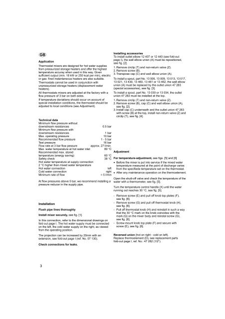
GB<br />
Application<br />
Thermostat mixers are designed for hot water supplies<br />
from pressurized storage heaters and offer the highest<br />
temperature accuray when used in this way. Given<br />
sufficient output (min. 18 kW or 250 kcal per min), electric<br />
or gas- fired instantaneous heaters are also suitable.<br />
Thermostats cannot be used in conjunction with<br />
unpressurized storage heaters (displacement water<br />
heaters).<br />
All thermostats mixers are adjusted at the factory with a<br />
flow pressure of 3 bar on both sides.<br />
If temperature deviations should occur on account of<br />
special installation conditions, the thermostat should be<br />
adjusted to local conditions (see Adjustment).<br />
Technical data<br />
Minimum flow pressure without<br />
downstream resistances 0.5 bar<br />
Minimum flow pressure with<br />
downstream resistances 1 bar<br />
Max. operating pressure 10 bar<br />
Recommended flow pressure 1 - 5 bar<br />
Test pressure 16 bar<br />
Flow rate at 3 bar flow pessure approx. 27 l/min.<br />
Max. water temperature at hot water inlet 80 °C<br />
Recommended max. stored<br />
temperature (energy saving) 60 °C<br />
Safety check 38 °C<br />
Hot water temperature at supply connection<br />
2 °C higher than mixed water temperature<br />
Hot water connection left<br />
Cold water connection right<br />
Minimum rate of flow = 5 l/min<br />
At flow pressures above 5 bar, we recommend installing a<br />
pressure reducer in the supply pipe.<br />
Installation<br />
Flush pipe lines thoroughly<br />
Install mixer securely, see fig. [1].<br />
In this connection, refer to the dimensional drawings on<br />
fold out page I. The hot water supply must be connected<br />
on the left, the cold water supply on the right, as viewed<br />
from the operating position.<br />
The projection can be increased by 20mm with an<br />
extension, see fold-out page I (ref. No. 07 130).<br />
Check connections for leaks.<br />
3<br />
Installing accessories<br />
To install outlet elbow 12 407 or 12 440 (see fold-out<br />
page I), the wall elbow union (A) must be repositioned,<br />
see fig. [2].<br />
1. Remove circlip (T) and non-return valve (Z).<br />
2. Remove screw (B).<br />
3. Transpose cap (C) and wall elbow union (A).<br />
To install a spout, part No. 13 005, 13 009, 13 013, 13 017,<br />
13 021, 13 430, 13 460, 13 461 or 13 462, the wall elbow<br />
union (A) must be replaced by the outlet union 47 283<br />
(special accessories), see fig. [3].<br />
To install a spout, part No. 13 030 or 13 034, the outlet<br />
union 47 283 must be installed at the top.<br />
1. Remove circlip (T) and non-return valve (Z).<br />
2. Remove screw (B), cap (C) and wall elbow union (A),<br />
see fig. [2].<br />
3. Install cap (C) underneath and the outlet union 47 283<br />
with screw (B) at the top, install non-return valve (Z) and<br />
circlip (T), see fig. [4].<br />
Adjustment<br />
For temperature-adjustment, see figs. [5] and [6]<br />
• Before the mixer is put into service if the mixed water<br />
temperature measured at the point of discharge varies<br />
from the specifiede temperature set on the thermostat.<br />
• After any maintenance operation on the thermoelement.<br />
Open the shutt-off valve and check the temperature of the<br />
water with a thermometer, see fig. [5].<br />
Turn the temperature control handle (X) until the water<br />
running out reaches 30 °C, see fig. [5].<br />
- Remove screw (E) and pull off knob top plates (F),<br />
see fig. [6].<br />
- Remove screw (G) and pull off thermostat knob (H),<br />
see fig. [6].<br />
- Pull off thermostat knob (H) and reinstall in such a way<br />
that the 30 °C mark on the knob coincides with the<br />
mark (Q) on the mixer body and reinstal screw (G),<br />
see fig. [6].<br />
- Screw-mount knob top plate (F) and secure with<br />
screw (E), see fig. [6].<br />
Reversed union (hot on right - cold on left).<br />
Replace thermoelement (D), see replacement parts<br />
fold-out page I, ref. No.: 47 282 (1/2”).


