GEWISS - MATERIALE ELETTRICO
GEWISS - MATERIALE ELETTRICO
GEWISS - MATERIALE ELETTRICO

You also want an ePaper? Increase the reach of your titles
YUMPU automatically turns print PDFs into web optimized ePapers that Google loves.
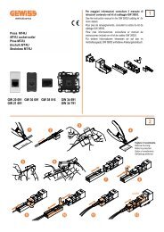
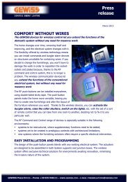
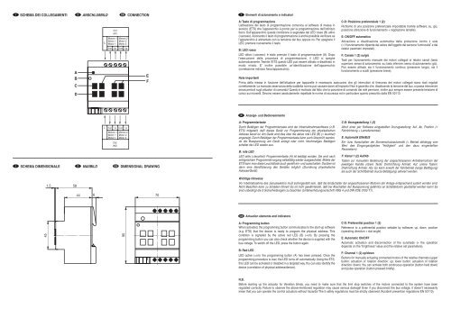
I SCHEMA DEI COLLEGAMENTI D ANSCHLUßBILD GB CONNECTION I<br />
Elementi di azionamento e indicatori<br />
A<br />
B<br />
C<br />
D<br />
L<br />
Ch1<br />
(K1)<br />
Motore 1<br />
Motor 1<br />
Motor 1<br />
Down Up<br />
Motore 2<br />
Motor 2<br />
Motor 2<br />
Down Up<br />
E<br />
F<br />
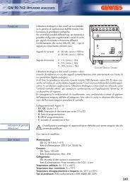
A: Tasto di programmazione<br />
L’attivazione del tasto di programmazione comunica al software di messa in<br />
servizio (ETS) che l’apparecchio è pronto per la programmazione dell’indirizzo<br />
fisico. Sull’apparecchio questa condizione è segnalata dal LED rosso (B) attivo<br />
(=acceso). Azionando il tasto di programmazione è anche possibile verificare se<br />
l’apparecchio è alimentato con la tensione del bus oppure no. Per spegnere il<br />
LED, premere nuovamente il tasto.<br />
B: LED rosso<br />
LED attivo (=acceso): è stato premuto il tasto di programmazione (A). Dopo<br />
l’esecuzione della procedura di programmazione, il LED si spegne<br />
automaticamente. Tramite l’ETS questo LED può essere attivato e disattivato in<br />
modo mirato. E’ inoltre possibile un’identificazione dell’apparecchio<br />
(correlazione indirizzo fisico/apparecchio).<br />
C-D: Posizione preferenziale 1 (2)<br />
Richiamo di una posizione preferenziale impostabile tramite software: su, giù,<br />
posizione (direzione di funzionamento + regolazione lamelle).<br />
E: ON/OFF automatico<br />
Attivazione e disattivazione automatica della protezione contro il sole<br />
(= il funzionamento dipende dal valore dell’oggetto del sensore “luminosità” e dai<br />
relativi parametri impostati).<br />
F: Canale 1 (2) su/giù<br />
Tasti per l’azionamento manuale dei motori collegati ai relativi canali (tasto<br />
superiore: senso di azionamento: su; tasto inferiore: senso di azionamento: giù).<br />
Può essere attivato sia il funzionamento continuo (pressione lunga), sia il<br />
funzionamento a scatti (pressione breve).<br />
Note importanti<br />
Prima della messa in funzione dell’attuatore per tapparelle è necessario assicurarsi che gli interruttori di finecorsa dei motori collegati siano stati regolati<br />
correttamente. La mancata osservanza della suddetta norma può causare danni all’impianto! Non è garantito che, disattivando la tensione del bus, si possa intervenire<br />
senza pericoli sugli attuatori di comando! Questo è motivato dal fatto che la posizione di comando dei relè permane, inoltre può sempre essere presente tensione di<br />
carico sui morsetti. Devono essere assolutamente rispettate le norme di sicurezza ed in particolare quanto prescritto dalla EN 50110.<br />
D<br />
Anzeige- und Bedienelemente<br />
L Down Up Down Up<br />
Motore 1<br />
Motor 1<br />
Motor 1<br />
Motore 2<br />
Motor 2<br />
Motor 2<br />
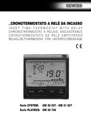
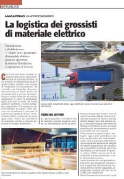
I SCHEMA DIMENSIONALE D MAßBILD GB DIMENSIONAL DRAWING<br />
Ch2<br />
(K2)<br />
A: Programmiertaste<br />
Durch Betätigen der Programmiertaste wird der Inbetriebnahmesoftware (z.B.<br />
ETS) mitgeteilt, daß dieses Gerät zur Programmierung der physikalischen<br />
Adresse bereit ist. Am Gerät wird dies über die aktive rote LED (B) (= leuchtet)<br />
angezeigt. Durch Betätigen der Programmiertaste kann auch überprüft werden,<br />
ob die Busspannung am Gerät anliegt oder nicht. Nochmaliges Betätigen<br />
schaltet die LED wieder aus.<br />
B: rote LED<br />
LED aktiv (=leuchtet): Programmiertaste (A) ist betätigt worden. Sie wird nach<br />
erfolgreichem Programmiervorgang selbsttätig wieder ausgeschaltet. Mittels der<br />
ETS kann man diese Leuchtdiode auch gezielt ein- und ausschalten. Darüber ist<br />
dann eine Identifizierung des Gerätes möglich (Zuordnung physikalische<br />
Adresse/Gerät).<br />
C-D: Vorzugsstellung 1 (2)<br />
Abruf einer per Software eingestellten Vorzugsstellung: Auf, Ab, Position (=<br />
Fahrtrichtung + Lamellenwinkel)<br />
E: Automatik EIN/AUS<br />
Ein- bzw. Ausschalten der Sonnenschutzautomatik (= Betrieb abhängig vom<br />
Wert des Eingangsobjektes "Helligkeit" und den dazu eingestellten<br />
Parametern).<br />
F: Kanal 1 (2) Auf/Ab<br />
Tasten zur manuellen Bedienung der angeschlossenen Antriebsmotoren der<br />
jeweiligen Kanäle (obere Taste: Drehrichtung Antrieb: Auf; untere Tasten:<br />
Drehrichtung Antrieb: Ab). Es kann sowohl der Fahrbetrieb (lange Betätigung)<br />
als auch der Schrittbetrieb (kurze Betätigung) aktiviert werden.<br />
1.5<br />
58<br />
Wichtige Hinweise<br />
Vor Inbetriebnahme des Jalousieaktors muß sichergestellt sein, daß die Endschalter der angeschlossenen Motoren der Anlage entsprechend justiert worden sind.<br />
Nicht Beachten kann zu Schäden führen! Es ist nicht gewährleistet, daß bei Abschalten der Busspannung gefahrlos an Schaltaktoren gearbeitet werden kann! Es<br />
sind unbedingt die 5 Sicherheitsregeln zu beachten (Unfallverhütungsvorschrift VBG 4 und DIN VDE 0105 T1).<br />
44 6<br />
70<br />
GB<br />
Actuation elements and indicators<br />
45<br />
90<br />
A: Programming button<br />
When activated, the programming button communicates to the start-up software<br />
(e.g. ETS) that the device is ready to program the physical address. This<br />
condition is signalled by the active red LED (B) (=on). By pressing the<br />
programming button you can also check whether the device is supplied with the<br />
bus voltage. To switch off the LED, press the button again.<br />
B: Red LED<br />
LED active (=on): the programming button (A) has been pressed. Once the<br />
programming procedure is over, the LED turns off automatically. Using the ETS,<br />
this LED can be activated or disabled in a targeted way.You can also identify the<br />
device (correlation of physical address/device).<br />
C-D: Preferential position 1 (2)<br />
Reference to a preferential position settable by software: up, down, position<br />
(operating direction + slat angle).<br />
E: Automatic ON/OFF<br />
Automatic activation and disconnection of the sunshade (= the operation<br />
depends on the “brightness” value and the relative set parameters).<br />
F: Channel 1 (2) up/down<br />
Buttons for manually actuating connected motors of the relative channels (upper<br />
button: actuation of rotation direction: up; lower button: actuation of rotation<br />
direction: down). You can activate both continuous operation (button held down)<br />
and pulse operation (button pressed briefly).<br />
N.B.<br />
Before starting up the actuator for Venetian blinds, you need to make sure that the limit stop switches of the motors connected to the system have been<br />
regulated correctly. Failure to observe the above-mentioned regulation may cause serious damage! Even if you disconnect the bus voltage, it doesn’t necessarily<br />
mean that you can operate the control actuators without hazards! The 5 safety regulations must be strictly observed (Accident prevention regulations EN 50110).