AXIS 225FD Network Camera Installation Guide - Moonblink ...
AXIS 225FD Network Camera Installation Guide - Moonblink ...
AXIS 225FD Network Camera Installation Guide - Moonblink ...

Create successful ePaper yourself
Turn your PDF publications into a flip-book with our unique Google optimized e-Paper software.
<strong>AXIS</strong> <strong>225FD</strong><br />
<strong>Network</strong> <strong>Camera</strong><br />
<strong>Installation</strong> <strong>Guide</strong><br />
ENGLISH DEUTSCH FRANCAIS ESPAÑOL ITALIANO
<strong>AXIS</strong> <strong>225FD</strong> <strong>Installation</strong> <strong>Guide</strong> Page 3<br />
<strong>AXIS</strong> <strong>225FD</strong><br />
Fixed Dome <strong>Network</strong> <strong>Camera</strong><br />
<strong>Installation</strong> <strong>Guide</strong><br />
This installation guide provides instructions for installing the <strong>AXIS</strong> <strong>225FD</strong> Fixed Dome<br />
<strong>Network</strong> <strong>Camera</strong> on your network. For all other aspects of using the product, please see the<br />
<strong>AXIS</strong> <strong>225FD</strong> User’s Manual, available from www.axis.com or on the Axis <strong>Network</strong> Video<br />
Product CD.<br />
<strong>Installation</strong> steps<br />
1. Check the package contents against the list below<br />
2. Install the hardware - page 5<br />
3. Connect the cables - page 5<br />
4. Set the IP address - page 9<br />
5. Set the password - page 9<br />
6. Adjust the image - page 10<br />
Package contents<br />
Fixed Dome <strong>Network</strong> <strong>Camera</strong><br />
Indoor Power Adapter<br />
Note: The power adapter is country specific,<br />
please check that the type of power adapter<br />
you are using is correct<br />
Mounting kit<br />
Documentation<br />
Warranty Document<br />
Important!<br />
This product must be installed in<br />
compliance with local laws and<br />
regulations.<br />
<strong>AXIS</strong> <strong>225FD</strong><br />
Europe<br />
UK<br />
Australia<br />
USA/Japan<br />
Korea<br />
Tool for tamper-proof screws<br />
3 screws and plugs for solid walls<br />
Cable gland with blind plugs<br />
Drill template<br />
Silica gel packet<br />
<strong>AXIS</strong> <strong>225FD</strong> <strong>Installation</strong> <strong>Guide</strong><br />
Axis <strong>Network</strong> Video Product CD<br />
ENGLISH DEUTSCH ESPAÑOL ITALIANO<br />
Note: To comply with the vandal resistant design of the <strong>AXIS</strong> <strong>225FD</strong>, it is necessary to use vandal<br />
resistant conduits to protect the cables.
Page 4<br />
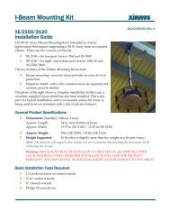
Hardware overview<br />
Tamper-proof<br />
screws<br />
I/O terminal<br />
block<br />
(see table 1)<br />
<strong>AXIS</strong> <strong>225FD</strong> <strong>Installation</strong> <strong>Guide</strong><br />
Power connector block<br />
1<br />
7<br />
AC<br />
GND<br />
+ or AC<br />
Dome casing<br />
Unit casing<br />
Conduit hole<br />
(side)<br />
Conduit hole<br />
(bottom)<br />
Control<br />
button<br />
Serial number (S/N)<br />
The serial number is required<br />
during the installation.<br />
<strong>Network</strong><br />
connector<br />
LED<br />
indicators<br />
1 2 3 4<br />
(see table 2)<br />
Conduit<br />
hole<br />
Plug<br />
Cables<br />
Cable<br />
gland<br />
Rubber<br />
plug<br />
Outer<br />
ring<br />
Cable<br />
gland<br />
Notes:<br />
• Use cables and conduits that are suitable for the installation and that are in compliance<br />
with the IP66 rated, outdoor-proof, vandal resistant design of the <strong>AXIS</strong> <strong>225FD</strong>.<br />
• Conduit dimensions: NPT 3/4" -14 (pipe thread).<br />
Important!<br />
If the <strong>AXIS</strong> <strong>225FD</strong> is not mounted according to the instructions, there may be problems with<br />
moisture which is not covered by warranty.
<strong>AXIS</strong> <strong>225FD</strong> <strong>Installation</strong> <strong>Guide</strong> Page 5<br />
Install the hardware<br />
Refer to the illustration on page 4 for a detailed overview of the <strong>AXIS</strong> <strong>225FD</strong>.<br />
1. Make a note of the serial number (S/N) which is located on the product label on the base<br />
of the unit casing. The serial number is used in the installation.<br />
2. Loosen the tamper-proof screws using the supplied allen key and lift the dome casing<br />
from the unit casing. Be careful not to damage the dome or scratch the glass.<br />
3. Disassemble the cable gland (see illustration).<br />
4. Thread the network/power and I/O cables through the outer ring<br />
and rubber plug (push the network cable through the slit).<br />
5. Use the supplied blind plugs to fill unused holes in the rubber plug.<br />
6. Attach the cable gland to the conduit hole on the side or bottom of<br />
the <strong>AXIS</strong> <strong>225FD</strong>, depending on the installation.<br />
7. Route the cables through the cable gland, push the rubber plug into<br />
place and tighten the outer ring to secure the cables. Use silicon<br />
sealant, if necessary.<br />
8. Using the drill template, drill three holes in the ceiling/wall.<br />
The conduit hole must face downwards if the camera is installed<br />
vertically.<br />
9. Install the unit casing on the ceiling/wall using the supplied screws and plugs. Seal the<br />
holes with silicon sealant to prevent moisture from leaking in to the casing.<br />
Note: Use of the cable gland is optional. For full vandal resistant protection of the cables, use<br />
vandal resistant conduits instead.<br />
Connect the cables<br />
Conduit hole<br />
must face<br />
downwards<br />
1. Connect the camera to the network using a shielded network cable.<br />
2. Optionally connect external input/output devices, e.g. alarm devices. See page 14 for<br />
information on the terminal connector pins.<br />
3. Connect power to the power connector block, using one of the methods listed below:<br />
• PoE (Power over Ethernet) via the network cable. This will automatically be detected if<br />
available via the network. Note that PoE provides power for the camera only (not the<br />
heater).<br />
• Connect the supplied indoor power adapter to the power connector block in the camera<br />
casing. Note that this indoor power adapter provides power for the camera only (not the<br />
heater).<br />
• Connect an outdoor power supply to the power connector block in the camera casing. For<br />
information on available outdoor power supplies, please visit the Support pages at http://<br />
www.axis.com/techsup/<br />
4. Check that the indicator LEDs indicate the correct conditions. See the table on page 14 for<br />
further details. Note that some LEDs can be disabled and may be unlit.<br />
ENGLISH DEUTSCH ESPAÑOL ITALIANO
Page 6<br />
<strong>AXIS</strong> <strong>225FD</strong> <strong>Installation</strong> <strong>Guide</strong><br />
Assign an IP address<br />
Most networks today have a DHCP server that automatically assigns IP addresses to connected<br />
devices. If your network does not have a DHCP server the <strong>AXIS</strong> <strong>225FD</strong> will use 192.168.0.90<br />
as the default IP address.<br />
If you would like to assign a static IP address the recommended method in Windows is either<br />
<strong>AXIS</strong> IP Utility or <strong>AXIS</strong> <strong>Camera</strong> Management. Depending on the number of cameras you<br />
wish to install, use the method that best suits your purpose.<br />
Both of these free applications are available on the Axis <strong>Network</strong> Video Product CD supplied<br />
with this product, or they can be downloaded from www.axis.com/techsup<br />
Method Recommended for Operating system<br />
<strong>AXIS</strong> IP Utility<br />
See page 7<br />
<strong>AXIS</strong> <strong>Camera</strong> Management<br />
See page 15<br />
Single camera<br />
Small installations<br />
Multiple cameras<br />
Large installations<br />
<strong>Installation</strong> on a different subnet<br />
Windows<br />
Windows 2000<br />
Windows XP Pro<br />
Windows 2003<br />
Server<br />
Notes:<br />
• If assigning the IP address fails, check that there is no firewall blocking the operation.<br />
• For other methods of assigning or discovering the IP address of the <strong>AXIS</strong> <strong>225FD</strong>, e.g. in other<br />
operating systems, see page 15.
<strong>AXIS</strong> <strong>225FD</strong> <strong>Installation</strong> <strong>Guide</strong> Page 7<br />
<strong>AXIS</strong> IP Utility - single camera/small installation<br />
<strong>AXIS</strong> IP Utility automatically discovers and displays Axis devices on your network. The<br />
application can also be used to manually assign a static IP address.<br />
Note that the computer running <strong>AXIS</strong> IP Utility must be on the same network segment<br />
(physical subnet) as the <strong>AXIS</strong> <strong>225FD</strong>.<br />
Automatic discovery<br />
1. Check that the <strong>AXIS</strong> <strong>225FD</strong> is connected to the network and that power has been applied.<br />
2. Start <strong>AXIS</strong> IP Utility.<br />
3. When the camera appears in the window, double-click it to open its home page.<br />
4. See page 9 for instructions on how to assign the password.<br />
Assign the IP address manually<br />
1. Acquire an unused IP address on the same network segment as your computer.<br />
2. Click the button Assign new IP address using serial number and enter the serial<br />
number and IP address for the <strong>AXIS</strong> <strong>225FD</strong>. The serial number is located on the product<br />
label.<br />
3. Click the Assign button and follow the instructions.<br />
4. Click the Home Page button to access the camera’s web pages.<br />
See page 9 for instructions on how to set the password<br />
ENGLISH DEUTSCH ESPAÑOL ITALIANO
Page 8<br />
<strong>AXIS</strong> <strong>225FD</strong> <strong>Installation</strong> <strong>Guide</strong><br />
<strong>AXIS</strong> <strong>Camera</strong> Management - multiple cameras/large installations<br />
<strong>AXIS</strong> <strong>Camera</strong> Management can<br />
automatically discover multiple<br />
Axis devices, show connection<br />
status, manage firmware upgrades<br />
and set IP addresses.<br />
Automatic discovery<br />
1. Check that the camera is connected<br />
to the network and that<br />
power has been applied.<br />
2. Start <strong>AXIS</strong> <strong>Camera</strong> Management. When the <strong>AXIS</strong> <strong>225FD</strong> appears in the window, doubleclick<br />
it to open the camera’s home page.<br />
3. See page 9 for instructions on how to set the password.<br />
Assign an IP address in a single device<br />
1. Select <strong>AXIS</strong> <strong>225FD</strong> in <strong>AXIS</strong> <strong>Camera</strong> Management and click<br />
the Assign IP button.<br />
2. Select Assign the following IP address and enter the IP<br />
address, subnet mask and default router the device will use.<br />
3. Click the OK button.<br />
Assign IP addresses in multiple devices<br />
<strong>AXIS</strong> <strong>Camera</strong> Management speeds up the process of assigning IP addresses to multiple devices,<br />
by suggesting IP addresses from a specified range.<br />
1. Select the devices you wish to configure (different models<br />
can be selected) and click the Assign IP button.<br />
2. Select Assign the following IP address range and enter the<br />
range of IP addresses, the subnet mask and default router<br />
the devices will use.<br />
3. Click the OK button.
<strong>AXIS</strong> <strong>225FD</strong> <strong>Installation</strong> <strong>Guide</strong> Page 9<br />
Setting the Password<br />
When accessing the <strong>AXIS</strong> <strong>225FD</strong> for the<br />
first time, the ‘Configure Root Password’<br />
dialog will be displayed on the screen.<br />
4. Enter a password and then re-enter it,<br />
to confirm the spelling. Click OK.<br />
5. Enter the User name: root<br />
Note: The default administrator user<br />
name root is permanent and cannot be<br />
deleted.<br />
6. Enter the password as set in step 2 above, and click OK. If the password is lost, the <strong>AXIS</strong><br />
<strong>225FD</strong> must be reset to the factory default settings. See page 15.<br />
7. If required, click Yes to install AMC (<strong>AXIS</strong> Media Control), to allow viewing of the video<br />
stream in your browser. You will need administrator rights on the computer to do this.<br />
8. The Live View page of the <strong>AXIS</strong> <strong>225FD</strong> is displayed, complete with links to the Setup<br />
tools, which allow you to customize the camera to your specific needs.<br />
9. Proceed to “Adjust the image” on page 10 to set the focus and zoom and complete the<br />
hardware installation.<br />
Help - Displays online help<br />
on all aspects of using the<br />
camera.<br />
Setup - Provides all the<br />
necessary tools for configuring<br />
the camera to suit<br />
your requirements.<br />
ENGLISH DEUTSCH ESPAÑOL ITALIANO
Page 10<br />
<strong>AXIS</strong> <strong>225FD</strong> <strong>Installation</strong> <strong>Guide</strong><br />
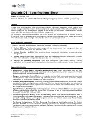
Adjust the image<br />
3 tamper-proof<br />
screws<br />
Focus puller<br />
Dome casing<br />
Unit casing<br />
Zoom<br />
puller<br />
Tilt<br />
adjustment<br />
screw<br />
Tilt<br />
adjustment<br />
screw<br />
Image<br />
balance<br />
ring<br />
Pan adjustment ring<br />
1. Open the Live View page in the Web interface and make the following adjustments:<br />
2. Loosen the pan adjustment ring and tilt adjustment screws. Hold the lens while turning the<br />
pan adjustment ring, otherwise the lens may rotate with the lock ring and damage or<br />
disconnect the cable.<br />
3. Turn the lens to the desired direction. Do not turn the lens more than 360° as this may<br />
cause the internal cables to disconnect.<br />
4. Once satisfied, gently tighten the pan adjustment ring and tilt adjustment screws to secure<br />
the camera’s position.<br />
5. Turn the image balance ring to set the image to the correct angle.<br />
6. Loosen the zoom puller counterclockwise, rotate the zoom ring and determine the desired<br />
zoom position.<br />
Note: Due to the dome’s refraction, the image might appear slightly out of focus once the dome has<br />
been placed. To compensate, focus on an object slightly closer than the intended area.
<strong>AXIS</strong> <strong>225FD</strong> <strong>Installation</strong> <strong>Guide</strong> Page 11<br />
7. Go to the Basic Configuration menu in the Web interface and select Focus. Follow the<br />
on-screen instructions to set the focus.<br />
8. After determining the zoom and focus, lock the zoom puller and the focus puller in<br />
position by rotating the screws clockwise.<br />
Note: The image can be fine-tuned for low lighting conditions.<br />
Go to 'Setup > Video & Image > Advanced' and refer to the help files for more information.<br />
Completing the installation<br />
1. Check that the safety cord is attached to the hook to prevent the dome casing from falling<br />
off the unit casing during the installation process. Be careful not to damage the dome or<br />
scratch the glass.<br />
2. Rotate the black protective shield inside the dome to match the camera’s position.<br />
3. Clean the dome with a dry soft cloth to remove dust and finger prints and use a blower to<br />
remove dust from the lens.<br />
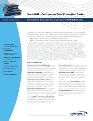
4. Remove the silica gel packet from the<br />
plastic bag and remove the protective paper<br />
from the adhesive strip. Place the silica gel<br />
packet on the camera unit as suggested in<br />
the illustration.<br />
5. Replace the dome casing and tighten the<br />
tamper-proof screws using the allen key.<br />
The installation is now complete.<br />
Place silica gel<br />
packet<br />
here<br />
ENGLISH DEUTSCH ESPAÑOL ITALIANO<br />
Note: The silica gel packet will absorb moisture<br />
trapped in the dome casing during installation. Be<br />
sure to attach the packet so it does not obstruct<br />
the camera, LED indicators or cable connections.
Page 12<br />
<strong>AXIS</strong> <strong>225FD</strong> <strong>Installation</strong> <strong>Guide</strong><br />
Other methods of setting the IP address<br />
The table below shows the other methods available for setting or discovering the IP address.<br />
All methods are enabled by default, and all can be disabled.<br />
UPnP<br />
Operating<br />
system<br />
Windows<br />
(ME or XP)<br />
Notes<br />
When enabled on your computer, the camera is automatically<br />
detected and added to “My <strong>Network</strong> Places.”<br />
Bonjour<br />
<strong>AXIS</strong> Dynamic<br />
DNS Service<br />
MAC OSX<br />
(10.4 or later)<br />
All<br />
Applicable to browsers with support for Bonjour. Navigate<br />
to the Bonjour bookmark in your browser (e.g. Safari) and<br />
click on the link to access the camera’s web pages.<br />
A free service from Axis that allows you to quickly and<br />
simply install your camera. Requires an Internet connection<br />
with no HTTP proxy. See www.axiscam.net for more<br />
information.<br />
ARP/Ping All See below. The command must be issued within 2 minutes<br />
of connecting power to the camera.<br />
View DHCP server<br />
admin pages<br />
All<br />
To view the admin pages for the network DHCP server, see<br />
the server’s own documentation.
<strong>AXIS</strong> <strong>225FD</strong> <strong>Installation</strong> <strong>Guide</strong> Page 13<br />
Setting the IP address with ARP/Ping<br />
1. Acquire an IP address on the same network segment your computer is connected to.<br />
2. Locate the serial number (S/N) on the <strong>AXIS</strong> <strong>225FD</strong> product label.<br />
3. Open a Command Prompt on your computer and enter the following commands<br />
(as appropriate for your operating system):<br />
Windows syntax:<br />
arp -s <br />
ping -l 408 -t <br />
Windows example:<br />
4. Check that the network cable is connected to the camera. Start/restart the camera by<br />
disconnecting and reconnecting power.<br />
5. Close the Command prompt when you see ‘Reply from 192.168.0.125: ...’ or similar.<br />
6. Start your browser, type in http:// in the Location/Address field and press<br />
Enter on your keyboard.<br />
7. See page 9 for instructions on how to set the password.<br />
Notes:<br />
arp -s 192.168.0.125 00-40-8c-18-10-00<br />
ping -l 408 -t 192.168.0.125<br />
UNIX/Linux/Mac syntax:<br />
arp -s temp<br />
ping -s 408 <br />
UNIX/Linux/Mac example:<br />
arp -s 192.168.0.125 00:40:8c:18:10:00 temp<br />
ping -s 408 192.168.0.125<br />
• The ARP/Ping command must be issued within 2 minutes of connecting power to the<br />
camera.<br />
• To open a command prompt in Windows: from the Start menu, select Run... and type<br />
cmd (or command in Windows 98/ME). Click OK.<br />
• To use the ARP command on a Mac OS X, use the Terminal utility, which is found under<br />
Application > Utilities.<br />
ENGLISH DEUTSCH ESPAÑOL ITALIANO
Page 14<br />
<strong>AXIS</strong> <strong>225FD</strong> <strong>Installation</strong> <strong>Guide</strong><br />
Table 1 - I/O terminal connector block<br />
Pin Function<br />
Table 2 - LED indicators<br />
Description<br />
1 Output A On the external device output terminals (A and B), there is no distinction<br />
2 Output B<br />
between positive and negative (+ and -). The terminals use a pho-<br />
tocoupler and are electrically isolated from the other internal<br />
circuitry.<br />
The maximum load should not exceed 100mA and the maximum voltage<br />
should be not more than 50V DC. Note: Connecting AC to the output<br />
will damage the unit.<br />
3 Digital Input 1 Connect to GND to activate, or leave floating (or unconnected) to<br />
4 Digital Input 2 deactivate.<br />
5 RS-485/422-A<br />
(non-inverting)<br />
6 RS-485/422-B<br />
(inverting)<br />
7 GND Ground.<br />
A half-duplex RS-485/422 interface for controlling auxiliary equipment.<br />
LED Function Color Description<br />
1 <strong>Network</strong> Green Steady for connection to 100 Mbit/s network. Flashes for network<br />
activity.<br />
Amber Steady for connection to 10 Mbit/s network. Flashes for network activity.<br />
Red Flashes rapid red, together with the Status indicator, for hardware<br />
error.<br />
Unlit No connection.<br />
2 Status Green Shows steady green for normal operation.<br />
Amber Shows steady amber during reset to factory default or when restoring<br />
settings.<br />
Red Slow flash for failed upgrade. Rapid flash, together with the <strong>Network</strong><br />
indicator, for hardware error.<br />
3 Heater Green Steady green when the power connected is sufficient for the heater<br />
i.e. (12V DC min 20W or 24V AC min 25VA)<br />
Red Insufficient power for the heater.<br />
4 Power Green Normal operation.<br />
Amber Flashes green/amber during firmware upgrade.
<strong>AXIS</strong> <strong>225FD</strong> <strong>Installation</strong> <strong>Guide</strong> Page 15<br />
Accessing the <strong>AXIS</strong> <strong>225FD</strong> from the Internet<br />
Once installed, your <strong>AXIS</strong> <strong>225FD</strong> is accessible on your local network (LAN). To access the<br />
camera from the Internet, network routers must be configured to allow incoming traffic,<br />
which is usually done on a specific port. Please refer to the documentation for your router for<br />
further instructions.<br />
For more information on this and other topics, please visit the Axis Support Web at<br />
www.axis.com/techsup<br />
Resetting to the Factory Default Settings<br />
This will reset all parameters, including the IP address, to the Factory Default settings:<br />
1. Disconnect power from the camera.<br />
2. Press and hold the Control button and reconnect power.<br />
3. Keep the control button pressed until the Power Indicator flashes amber (this may take up<br />
to 15 seconds).<br />
4. Release the control button.<br />
5. When the Power Indicator displays green (which can take up to 1 minute) the process is<br />
complete and the camera has been reset.<br />
6. Re-install the <strong>AXIS</strong> <strong>225FD</strong> using one of the methods described in this document.<br />
More information<br />
Please refer to the help files and the user’s manual for information on the functionality of the<br />
<strong>AXIS</strong> <strong>225FD</strong>. The <strong>AXIS</strong> <strong>225FD</strong> User’s Manual is available from the Axis Web site at http://<br />
www.axis.com or from the Axis <strong>Network</strong> Video Product CD.<br />
ENGLISH DEUTSCH ESPAÑOL ITALIANO
<strong>AXIS</strong> <strong>225FD</strong> <strong>Guide</strong> d’installation Page 17<br />
<strong>AXIS</strong> <strong>225FD</strong><br />
<strong>Guide</strong> d’installation<br />
Ce guide d’installation vous explique comment installer l’ <strong>AXIS</strong> <strong>225FD</strong> Fixed Dome <strong>Network</strong><br />
<strong>Camera</strong> sur votre réseau. Pour d’autres informations sur l’utilisation de ce produit, consultez<br />
le Manuel de l’utilisateur de l’ <strong>AXIS</strong> <strong>225FD</strong> disponible sur le CD d’installation ou surfez sur<br />
www.axis.com.<br />
Étapes de l’installation<br />
1. Vérifiez le contenu de la livraison à l’aide de la liste ci-dessous.<br />
2. <strong>Installation</strong> du matériel - page 19<br />
3. Branchement des câbles - page 20<br />
4. Paramétrage de l’adresse IP - page 21<br />
5. Définition du mot de passe - page 24<br />
Important !<br />
6. Réglage de l‘image - page 30.<br />
Ce produit doit être installé<br />
conformément à la réglementation<br />
en vigueur dans votre pays.<br />
Contenu de l’emballage<br />
Article<br />
Fixed Dome <strong>Network</strong> <strong>Camera</strong><br />
Alimentation intérieure<br />
Remarque : l’alimentation varie selon le pays.<br />
Vérifiez que l’alimentation que vous utilisez est<br />
adaptée.<br />
Kit de montage<br />
Documentation<br />
Document de garantie<br />
Titre/variantes<br />
<strong>AXIS</strong> <strong>225FD</strong><br />
Europe<br />
Royaume-Uni<br />
Australie<br />
États-Unis / Japon<br />
Corée<br />
Clé hexagonale pour vis inviolables<br />
3 vis et chevilles pour murs pleins<br />
Presse-étoupe avec chevilles aveugles<br />
Gabarit de perçage<br />
Sachet de gel de silice<br />
<strong>AXIS</strong> <strong>225FD</strong><strong>Guide</strong> d’installation<br />
CD d’installation d’Axis<br />
FRANCAIS
Page 18<br />
<strong>AXIS</strong> <strong>225FD</strong> <strong>Guide</strong> d’installation<br />
Description<br />
Connecteurs<br />
d’alimentation<br />
CA<br />
GND<br />
+ ou CA<br />
Vis inviolables<br />
7<br />
1<br />
Terminaux E/S<br />
(voir tableau 1)<br />
Boîtier du dôme<br />
Boîtier<br />
Trou de conduit<br />
(latéral)<br />
Trou de conduit<br />
(bas)<br />
Bouton de<br />
commande<br />
Le numéro de série (S/N) est nécessaire<br />
pendant l’installation.<br />
Notez le numéro de série et conservez-le<br />
pour une utilisation ultérieure.<br />
Câbles<br />
Presseétoupe<br />
Presseétoupe<br />
Connecteur<br />
réseau<br />
Cheville en<br />
caoutchouc<br />
Témoins DEL<br />
1 2 3 4<br />
(voir tableau 2)<br />
Bague<br />
extérieure<br />
Trou de<br />
conduit<br />
Remarques :<br />
• Utilisez des câbles, des presse-étoupe et des conduits adaptés à l’installation et à l’<strong>AXIS</strong> <strong>225FD</strong>,<br />
qui est conforme à l’indice de protection IP66, utilisable en extérieure et anti-effraction.<br />
• Dimensions des conduits : NPT 3/4" -14 (filetage du tuyau).<br />
Important!<br />
Si la caméra <strong>AXIS</strong> <strong>225FD</strong> est montée de manière incorrecte, vous pouvez rencontrer des<br />
problèmes d'humidité, non couverts par la garantie.
<strong>AXIS</strong> <strong>225FD</strong> <strong>Guide</strong> d’installation Page 19<br />
<strong>Installation</strong> du matériel<br />
Reportez-vous à l’illustration à la page 18 pour une représentation détaillée de l’ <strong>AXIS</strong><br />
<strong>225FD</strong>.<br />
1. Notez le numéro de série (S/N) de l’étiquette située au bas du boîtier. Le numéro de série<br />
sera nécessaire pendant l’installation.<br />
2. Desserrez les vis inviolables à l’aide de la clé hexagonale fournie et soulevez le boîtier du<br />
dôme. Veillez à ne pas endommager le dôme ni à rayer la vitre.<br />
3. Démontez le presse-étoupe (voir l’illustration).<br />
4. Faites passer les câbles de réseau et d’alimentation ainsi que les<br />
câbles d’E/S à travers la bague extérieure et la cheville en<br />
caoutchouc (poussez le câble de rèseau à travers la fente).<br />
5. Utilisez les chevilles aveugles fournies pour remplir les trous non<br />
utilisés dans la cheville en caoutchouc.<br />
6. Fixez le presse-étoupe au trou de conduit situé sur le côté ou au<br />
bas de la caméra Axis <strong>225FD</strong>, en fonction de l’installation.<br />
Le trou du conduit<br />
latéral doit être<br />
7. Acheminez les câbles à travers le presse-étoupe, mettez en place la<br />
cheville en caoutchouc en la poussant et serrez la bague extérieure<br />
tourné vers le bas<br />
pour fixer les câbles. Si nécessaire, utilisez du joint silicone pour<br />
rendre le tout bien étanche.<br />
8. Avec le gabarit de perçage, percez trois trous dans le plafond/mur. Le trou du conduit<br />
latéral doit être tourné vers le bas si la caméra est installée à la verticale.<br />
9. Fixez le boîtier au plafond/mur avec les vis et chevilles fournies. Refermez les trous avec<br />
du joint silicone pour rendre le boîtier étanche.<br />
Remarque:<br />
L'utilisation du presse-étoupe est facultative. Pour protéger les câbles contre toute effraction,<br />
utilisez plutôt des conduits anti-effraction.<br />
FRANCAIS
Page 20<br />
<strong>AXIS</strong> <strong>225FD</strong> <strong>Guide</strong> d’installation<br />
Branchement des câbles<br />
1.Branchez le câble réseau au connecteur de réseau de la caméra.<br />
2. Branchez l’alimentation au connecteur d’alimentation, de l’une des manières suivantes :<br />
• PoE (Power over Ethernet) via le câble réseau. Cette connexion sera automatiquement<br />
détectée si elle est disponible via le réseau. La PoE alimente la caméra uniquement (par le<br />
réchauffeur).<br />
• Branchez l’alimentation intérieure fournie au connecteur d’alimentation dans le boîtier de la<br />
caméra. De même, cette alimentation intérieure alimente la caméra uniquement (par le<br />
réchauffeur).<br />
• Branchez l’alimentation extérieure au connecteur d’alimentation dans le boîtier de la<br />
caméra. Pour connaître la liste des alimentations extérieures disponibles, consultez les pages<br />
de Support à l’adresse http://www.axis.com/techsup/<br />
3. Vérifiez que les voyants du réseau, d’état et d’alimentation sont allumés et verts. Si vous<br />
souhaitez utiliser le réchauffeur, vérifiez que son voyant est allumé et vert. Consultez le<br />
tableau à la page 29 pour en savoir plus sur les voyants.<br />
4. Reportez-vous à la section “Attribution d'une adresse IP” on page 21 pour savoir<br />
comment assigner une adresse IP à l’ <strong>AXIS</strong> <strong>225FD</strong>.
<strong>AXIS</strong> <strong>225FD</strong> <strong>Guide</strong> d’installation Page 21<br />
Attribution d'une adresse IP<br />
Aujourd'hui, la plupart des réseaux comportent un serveur DHCP qui attribue<br />
automatiquement des adresses IP aux dispositifs connectés. Si ce n'est pas le cas de votre<br />
réseau, l'<strong>AXIS</strong> <strong>225FD</strong> utilisera l'adresse IP par défaut 192.168.0.90.<br />
Si vous souhaitez affecter une adresse IP statique, sous Windows nous recommandons<br />
l'utilisation de l'application <strong>AXIS</strong> IP Utility ou de l'application <strong>AXIS</strong> <strong>Camera</strong> Management.<br />
Selon le nombre de caméras à installer, utilisez la méthode qui vous convient le mieux.<br />
Ces deux applications gratuites sont disponibles sur le CD de la caméra vidéo réseau Axis<br />
fourni avec ce produit. Vous pouvez également les télécharger à partir du site www.axis.com/<br />
techsup.<br />
Méthode Recommandée pour Système<br />
d'exploitation<br />
<strong>AXIS</strong> IP Utility<br />
Voir page 22<br />
<strong>AXIS</strong> <strong>Camera</strong> Management<br />
Voir page 23<br />
Une seule caméra<br />
Les petites installations<br />
Plusieurs caméras<br />
Les grandes installations<br />
<strong>Installation</strong> sur un autre sousréseau<br />
Windows<br />
Windows 2000<br />
Windows XP Pro<br />
Windows 2003 Server<br />
Remarques :<br />
• En cas d'échec de l'attribution de l'adresse IP, vérifiez qu'aucun pare-feu ne bloque<br />
l'opération.<br />
• Pour connaître les autres méthodes d'affectation ou de repérage de l'adresse IP de la<br />
caméra <strong>AXIS</strong> <strong>225FD</strong>, par exemple sur d'autres systèmes d'exploitation, reportez-vous à la<br />
page 27.<br />
FRANCAIS
Page 22<br />
<strong>AXIS</strong> <strong>225FD</strong> <strong>Guide</strong> d’installation<br />
<strong>AXIS</strong> IP Utility - Une seule caméra/petite installation<br />
L'utilitaire <strong>AXIS</strong> IP Utility détecte et affiche automatiquement les périphériques Axis de votre<br />
réseau. Cette application sert également à attribuer manuellement une adresse IP statique.<br />
Notez que l'ordinateur exécutant l'application <strong>AXIS</strong> IP Utility doit se trouver sur le même<br />
segment de réseau (sous-réseau physique) que l'appareil <strong>AXIS</strong> <strong>225FD</strong>.<br />
Détection automatique<br />
1. Vérifiez que l'appareil <strong>AXIS</strong> <strong>225FD</strong> est connecté au réseau et que l'alimentation est<br />
activée.<br />
2. Démarrez <strong>AXIS</strong> IP Utility.<br />
3. Lorsque l'icône de la caméra apparaît dans la fenêtre, double-cliquez dessus pour ouvrir<br />
la page d'accueil correspondante.<br />
4. Consultez la page 30 pour savoir comment affecter le mot de passe.<br />
Affectez manuellement l'adresse IP.<br />
1. Trouvez une adresse IP inutilisée sur le même segment de réseau que celui de votre ordinateur.<br />
2. Cliquez sur le bouton Affecter l'adresse IP en utilisant le numéro de série, puis<br />
saisissez le numéro de série et l'adresse IP de l'<strong>AXIS</strong> <strong>225FD</strong>. Le numéro de série se trouve<br />
sur l'étiquette du produit.<br />
3. Cliquez sur le bouton Affecter et suivez les instructions.<br />
4. Cliquez sur le bouton Page d’accueil pour accéder aux pages Web de la caméra.<br />
5. Consultez la page 30 pour savoir comment définir le mot de passe.
<strong>AXIS</strong> <strong>225FD</strong> <strong>Guide</strong> d’installation Page 23<br />
<strong>AXIS</strong> <strong>Camera</strong> Management - Plusieurs caméras/grandes installations<br />
<strong>AXIS</strong> <strong>Camera</strong> Management peut détecter automatiquement plusieurs dispositifs Axis, afficher<br />
les états de connexion, gérer les mises à niveau du microcode et définir les adresses IP.<br />
Détection automatique<br />
1. Vérifiez que la caméra est connectée au réseau et que l'alimentation est activée.<br />
2. Démarrez <strong>AXIS</strong> <strong>Camera</strong> Management. Double-cliquez sur l'icône de l'<strong>AXIS</strong> <strong>225FD</strong><br />
lorsqu'elle apparaît dans la fenêtre de façon à ouvrir la page d'accueil.<br />
3. Consultez la page 30 pour savoir comment définir le mot de passe.<br />
Attribuer une adresse IP à un seul dispositif<br />
1. Sélectionnez <strong>AXIS</strong> <strong>225FD</strong> dans l'application <strong>AXIS</strong> <strong>Camera</strong><br />
Management, puis cliquez sur le bouton Affecter une<br />
IP<br />
2. Sélectionnez Affecter l’adresse IP suivante et saisissez<br />
l'adresse IP, le masque de sous-réseau et le routeur par<br />
défaut que le dispositif utilisera.<br />
3. Cliquez sur le bouton OK.<br />
FRANCAIS<br />
Attribuer des adresses IP à plusieurs dispositifs<br />
<strong>AXIS</strong> <strong>Camera</strong> Management accélère le processus d'affectation d'adresses IP sur plusieurs<br />
appareils en suggérant les adresses IP parmi une plage spécifiée.<br />
1. Sélectionnez les appareils à configurer (il peut s'agir de<br />
plusieurs modèles), puis cliquez sur le bouton Affecter<br />
une adresse IP.<br />
2. Sélectionnez Affecter la plage d’adresses IP suivante et l<br />
saisissez la plage d'adresses IP, le masque de sous-réseau<br />
et le routeur par défaut que les dispositifs utiliseront.<br />
3. Cliquez sur le bouton OK.
Page 24<br />
<strong>AXIS</strong> <strong>225FD</strong> <strong>Guide</strong> d’installation<br />
Définition du mot de passe<br />
Si vous accédez à la caméra <strong>AXIS</strong> <strong>225FD</strong><br />
pour la première fois, la boîte de dialogue «<br />
Configure Root Password » s’affiche sur<br />
l’écran.<br />
1. Entrez un mot de passe et entrez-le une<br />
seconde fois pour en confirmer<br />
l’orthographe. Cliquez sur OK.<br />
2. Entrez le nom d’utilisateur : root<br />
Remarque : Le nom d’utilisateur par<br />
défaut de l’administrateur, à savoir root, est permanent et ne peut pas être supprimé.<br />
3. Entrez le mot de passe comme expliqué à l’étape 2 et cliquez sur OK. Si vous avez oublié<br />
votre mot de passe, vous devrez rétablir les paramètres d’usine de la caméra <strong>AXIS</strong> <strong>225FD</strong>.<br />
Reportez-vous à la page 30.<br />
4. Si nécessaire, cliquez sur Oui pour installer AMC (Axis Media Control) afin de pouvoir<br />
voir le flot vidéo dans votre navigateur. Pour ce faire, vous devrez être connecté à votre<br />
ordinateur avec les droits d’administrateur.<br />
5. La page Live View de la caméra <strong>AXIS</strong> <strong>225FD</strong> s’affiche, avec des liens vers les outils de<br />
configuration qui vous permettent d’adapter la caméra à vos propres besoins.<br />
6. Consultez la section “Accès à la caméra <strong>AXIS</strong> <strong>225FD</strong> depuis Internet” on page 30 pour<br />
régler la mise au point et le zoom et terminer l’installation du matériel.<br />
Help - affiche une aide en<br />
ligne sur tous les modes<br />
d’utilisation de la caméra.<br />
Setup - contient tous les<br />
outils nécessaires pour<br />
adapter la caméra à vos<br />
besoins.
<strong>AXIS</strong> <strong>225FD</strong> <strong>Guide</strong> d’installation Page 25<br />
Réglage de l‘image<br />
3 vis<br />
inviolables<br />
Mise au point<br />
Vis de<br />
réglage de<br />
l’inclinaison<br />
Boîtier du dôme<br />
Boîtier<br />
Zoom<br />
Vis<br />
de réglage<br />
de<br />
l’inclinaison<br />
Bague de réglage du panoramique<br />
Bague<br />
de réglage<br />
de la<br />
balance de<br />
l’image<br />
1. Ouvrez la page Live View dans l’interface Internet et effectuez les réglages suivants :<br />
2. Dévissez la bague de réglage du panoramique et les vis de réglage de l’inclinaison. Tenez<br />
l’objectif tout en tournant la bague du panoramique. À défaut, l’objectif pourrait tourner<br />
avec la bague de blocage et endommager et déconnecter le câble.<br />
3. Tournez l’objectif dans le sens souhaité. Ne pas tourner l’objectif à plus de 360° pour ne<br />
pas débrancher les câbles internes.<br />
4. Une fois que vous avez terminé, serrez délicatement la barre du panoramique et les vis de<br />
réglage de l’inclinaison pour bien fixer la caméra.<br />
5. Tournez la vis de réglage de la balance pour définir un angle adéquat.<br />
6. Desserrez le zoom dans le sens contraire des aiguilles d’une montre, tournez la bague du<br />
zoom et choisissez la position du zoom.<br />
Remarque: Dû à la réfraction du dôme, l’image peut apparaître lègèrement hors du foyer une fois<br />
que le dôme est placé, Pour compenser, il faut mettre le foyer légèrement proche de la<br />
zone préfèrée.<br />
FRANCAIS
Page 26<br />
<strong>AXIS</strong> <strong>225FD</strong> <strong>Guide</strong> d’installation<br />
7. Dans le menu Basic<br />
Configuration<br />
(configuration de base)<br />
de l’interface Internet,<br />
sélectionnez Focus (mise<br />
au point). Suivez les<br />
instructions affichées<br />
sur l’écran pour la mise<br />
au point.<br />
8. Une fois le zoom et la<br />
mise au point réglés,<br />
verrouillez le zoom et la<br />
mise au point en tournant les vis adéquats dans le sens des aiguilles d’une montre.<br />
Remarque: L’image peut être ajustée en cas de faible éclairage. Accédez à « Setup > Video & Image ><br />
Advanced » et consultez les fichiers d’aide pour en savoir plus.<br />
Terminer l’installation<br />
1. Vérifiez que le cordon de sécurité est attaché au crochet pour empêcher le dôme de<br />
tomber du boîtier pendant l’installation. Veillez à ne pas endommager le dôme ni à rayer<br />
la vitre.<br />
2. Tournez l’écran protecteur noir à l’intérieur du dôme conformément à la position de la<br />
caméra.<br />
3. Nettoyez le dôme avec un chiffon doux et sec pour enlever la poussière et les traces de<br />
doigt. Dépoussiérez l’objectif avec un ventilateur.<br />
4. Retirer le sachet de gel de silice (ou<br />
silica gel) du sac plastique et enlever le<br />
papier de protection des bandes<br />
adhésives. Placer le sachet de gel de<br />
silice sur la caméra - voir illustration.<br />
5. Remettez le boîtier du dôme en place<br />
et serrez les vis inviolables avec la clé<br />
hexagonale. L’installation est<br />
terminée.<br />
Placer le sachet de<br />
gel de silice ici<br />
Remarque: Le sachet de gel de silice absorbera<br />
la condensation piégée dans le<br />
dome durant l'installation du produit. Faire attention de bien attacher le sachet pour qu'il<br />
ne gêne pas la camera, les connecteurs ou les voyants.
<strong>AXIS</strong> <strong>225FD</strong> <strong>Guide</strong> d’installation Page 27<br />
Autres méthodes de définition de l'adresse IP<br />
Le tableau ci-dessous indique les autres méthodes permettant de définir ou de déterminer<br />
l'adresse IP. Toutes les méthodes sont activées par défaut et désactivables.<br />
UPnP<br />
Système<br />
d'exploitation<br />
Windows<br />
(ME ou XP)<br />
Remarques<br />
Lorsque la caméra est activée sur votre ordinateur, elle est détectée et<br />
ajoutée automatiquement au dossier Favoris réseau.<br />
Bonjour<br />
<strong>AXIS</strong> Internet<br />
Dynamic DNS<br />
Service<br />
MAC OSX<br />
(10.4 ou version<br />
ultérieure)<br />
Tous<br />
Applicable aux navigateurs prenant en charge Bonjour. Accédez au raccourci<br />
de Bonjour dans votre navigateur (par exemple, Safari), puis cliquez<br />
sur le lien pour accéder aux pages Web de la caméra.<br />
Service Axis gratuit vous permettant d'installer rapidement votre caméra<br />
en toute simplicité. Nécessite une connexion Internet sans proxy HTTP Pour<br />
plus d'informations, visitez le site www.axiscam.net.<br />
ARP/Ping Tous Reportez-vous aux instructions ci-dessous. La commande doit être saisie<br />
dans les 2 minutes suivant la connexion de l'alimentation à la caméra.<br />
Serveur DHCP Tous<br />
Pour consulter les pages administratives du serveur DHCP réseau, reportezvous<br />
à la documentation du serveur.<br />
FRANCAIS
Page 28<br />
<strong>AXIS</strong> <strong>225FD</strong> <strong>Guide</strong> d’installation<br />
Définition de l'adresse IP à l'aide d'ARP/Ping<br />
1. Trouvez une adresse IP sur le même segment de réseau que celui de votre ordinateur.<br />
2. Repérez le numéro de série (S/N) sur l'étiquette de la caméra <strong>AXIS</strong> <strong>225FD</strong>.<br />
3. Ouvrez une invite de commande sur votre ordinateur et entrez les commandes suivantes :<br />
Syntaxe pour Windows<br />
arp -s <br />
ping -l 408 -t <br />
Exemple pour Windows<br />
arp -s 192.168.0.125 00-40-8c-18-10-00<br />
ping -l 408 -t 192.168.0.125<br />
Syntaxe pour UNIX/Linux/Mac<br />
arp -s temp<br />
ping -s 408 <br />
Exemple pour UNIX/Linux/Mac<br />
arp -s 192.168.0.125 00:40:8c:18:10:00 temp<br />
ping -s 408 192.168.0.125<br />
4. Vérifiez que le câble réseau est connecté à la caméra, puis démarrez/redémarrez cette<br />
dernière en débranchant, puis en rebranchant l'alimentation.<br />
5. Fermez la commande d'invite quand vous voyez « Reply from 192.168.0.125: ...’ (Réponse<br />
de 192.168.0.125 : ...) ou un message similaire.<br />
6. Dans votre navigateur, tapez http:// dans le champ Emplacement/Adresse,<br />
puis appuyez sur Entrée sur le clavier.<br />
Remarques :<br />
• Pour ouvrir une invite de commande sous Windows : dans le menu Démarrer, sélectionnez Exécuter...<br />
et tapez cmd. Cliquez sur OK.<br />
• Pour utiliser la commande ARP sur Mac OS X, utilisez l'utilitaire Terminal dans Application > Utilitaires.
<strong>AXIS</strong> <strong>225FD</strong> <strong>Guide</strong> d’installation Page 29<br />
Tableau 1 – Connecteurs pour terminaux E/S :<br />
Bro<br />
che<br />
Fonction<br />
Description<br />
1 Sortie A Sur les terminaux de sortie externes (A et B), il n’y a aucune distinction entre le<br />
2 Sortie B<br />
positif et le négatif (+ et -). Les terminaux utilisent un photocoupleur et sont<br />
isolés électriquement de l’autre circuit interne.<br />
La charge maximale autorisée est de 100 mA et la tension maximale ne doit<br />
pas dépasser 50V DC. Remarque : si vous branchez l’alimentation CA à la sortie,<br />
l’appareil sera endommagé.<br />
3 Entrée numérique 1 Connectez au GND pour l’activer ou laissez flotter (ou déconnectée) pour la<br />
4 Entrée numérique 2 désactiver.<br />
5 RS-485/422-A<br />
(non inverseuse)<br />
6 RS-485/422-B<br />
(inverseuse)<br />
7 GND Terre.<br />
Une interface RS-485/422 bidirectionnelle non simultanée pour commander le<br />
matériel auxiliaire.<br />
Tableau 2 - Témoins DEL :<br />
DEL Fonction Couleur Description<br />
1 Connecteur Vert Continu en cas de connexion à un réseau 100 Mbits/s. Clignote en cas d’activité<br />
réseau.<br />
Orange Continu en cas de connexion à un réseau 10 Mbits/s. Clignote en cas d’activité<br />
réseau.<br />
Rouge Clignote rapidement en rouge, avec le voyant d’état, pour signaler une panne<br />
du matériel.<br />
Éteint Pas de connexion.<br />
2 État Vert Vert continu en cas de fonctionnement normal.<br />
Orange Orange en continu pendant la réinitialisation des valeurs d’usine ou des<br />
paramètres.<br />
Rouge Clignote lentement en cas d’échec de la mise à niveau. Clignote rapidement,<br />
avec le témoin du réseau, pour signaler une panne du matériel.<br />
3 Réchauffeur Vert Vert en continu lorsque le réchauffeur est suffisamment alimenté<br />
(12V DC min. 20W ou 24V CA min. 25VA)<br />
Rouge Alimentation insuffisante du réchauffeur.<br />
4 Alimentation<br />
Vert Fonctionnement normal.<br />
Orange Clignote en vert/orange pendant la mise à niveau du<br />
microprogramme.<br />
FRANCAIS
Page 30<br />
<strong>AXIS</strong> <strong>225FD</strong> <strong>Guide</strong> d’installation<br />
Accès à la caméra <strong>AXIS</strong> <strong>225FD</strong> depuis Internet<br />
Une fois installée, votre caméra <strong>AXIS</strong> <strong>225FD</strong> est accessible depuis votre réseau local (LAN).<br />
Pour accéder à la caméra depuis Internet, vous devez configurer les routeurs réseau afin<br />
d’autoriser l’entrée de données, ce qui se fait généralement sur un port spécifique. Consultez la<br />
documentation de votre routeur pour obtenir davantage d’instructions.<br />
Pour de plus amples informations, visitez le site de support d’Axis sur www.axis.com/techsup.<br />
Rétablissement des paramètres par défaut définis en usine<br />
Procédez comme suit pour revenir aux paramètres par défaut définis en usine et réinitialiser<br />
l’adresse IP :<br />
1. Débranchez l’alimentation de la caméra.<br />
2. Maintenez enfoncé le bouton de commande et rebranchez l’alimentation.<br />
3. Appuyez sur le bouton jusqu’à ce que le voyant d’alimentation passe à l’orange et<br />
clignote (cela peut prendre jusqu’à 15 secondes).<br />
4. Relâchez le bouton.<br />
5. Quand le voyant d’alimentation émet une lumière verte (ce qui peut prendre jusqu’à 1<br />
minute), la caméra est revenue aux réglages par défaut définis en usine.<br />
6. Réinstallez la caméra <strong>AXIS</strong> <strong>225FD</strong> à l’aide d’une des méthodes d’installation décrites dans<br />
ce document.<br />
Informations complémentaires<br />
Consultez les fichiers d’aide et le manuel de l’utilisateur pour en savoir plus sur les fonctions<br />
de l’ <strong>AXIS</strong> <strong>225FD</strong>. Le Manuel d'utilisation de l’ <strong>AXIS</strong> <strong>225FD</strong> est disponible sur le site Web<br />
d'Axis à l'adresse http://www.axis.com et sur le CD d’installation d’Axis.
<strong>AXIS</strong> <strong>225FD</strong> Montageanweisung Seite 31<br />
<strong>AXIS</strong> <strong>225FD</strong><br />
Montageanweisung<br />
In dieser Anleitung wird die <strong>Installation</strong> der Kamera <strong>AXIS</strong> <strong>225FD</strong> Fixed Dome <strong>Network</strong><br />
<strong>Camera</strong> im Netzwerk beschrieben. Alle anderen Aspekte der Nutzung dieses Produkts werden<br />
im <strong>AXIS</strong> <strong>225FD</strong> Benutzerhandbuch beschrieben, das sich auf der mitgelieferten Axis<br />
<strong>Installation</strong>s-CD befindet. Sie können das Benutzerhandbuch auch von unserer Website<br />
www.axis.com herunterladen.<br />
<strong>Installation</strong>sschritte<br />
1. Prüfen Sie, ob alle in der weiter unten folgenden Liste aufgeführten Komponenten vorhanden<br />
sind.<br />
2. Installieren Sie die Hardware – Seite 33.<br />
3. Schließen Sie die Kamera an – Seite 34.<br />
4. Legen Sie die IP-Adresse fest – Seite 35.<br />
5. Legen Sie das Kennwort fest – Seite 38.<br />
6. Stellen Sie das Bild ein – Seite 39.<br />
Wichtig!<br />
Die <strong>Installation</strong> dieses Produkts<br />
muss in Übereinstimmung mit den<br />
geltenden Gesetzen und<br />
Bestimmungen erfolgen<br />
DEUTSCH<br />
Lieferumfang<br />
Komponente<br />
Fixed Dome <strong>Network</strong> <strong>Camera</strong><br />
Netzteil für geschlossene Räume<br />
Hinweis: Das Netzteil ist landesspezifisch. Stellen<br />
Sie sicher, dass Sie das richtige Netzteil verwenden.<br />
Montagesatz<br />
Dokumentation<br />
Garantieerklärung<br />
Bezeichnung/Variante<br />
<strong>AXIS</strong> <strong>225FD</strong><br />
Europa<br />
Großbritannien<br />
Australien<br />
USA/Japan<br />
Korea<br />
inbus-Schlüssel für zugriffssichere Schrauben<br />
3 Schrauben und Dübel für feste Wände<br />
Kabeldurchführung mit Blindstecker<br />
Bohrschablone<br />
Silikagelpäckchen<br />
<strong>AXIS</strong> <strong>225FD</strong> <strong>Installation</strong>sanleitung<br />
Axis <strong>Installation</strong>s-CD
Seite 32<br />
<strong>AXIS</strong> <strong>225FD</strong> Montageanweisung<br />
Beschreibung<br />
zugriffssichere<br />
Schrauben<br />
Stromanschlussleiste<br />
1<br />
7<br />
AC<br />
Masse<br />
+ oder AC<br />
Kuppelhaube<br />
Kameragehäuse<br />
Kabelöffnung<br />
(Seite)<br />
Kabelöffnung<br />
(Unterseite)<br />
Seriennummer (S/N)<br />
Die Seriennummer wird<br />
für die <strong>Installation</strong> benötigt.<br />
Kabelöffnung<br />
Stopfen<br />
Kabel<br />
Kabeldurchführung<br />
Verschlussstopfen<br />
Netzwerkanschluss<br />
Steuertaste<br />
LEDanzeigen<br />
1 2 3 4<br />
(siehe Tabelle 2)<br />
E/A-Anschlussleiste<br />
(siehe Tabelle 1)<br />
Ausenring<br />
Kabeldurchführung<br />
Hinweise:<br />
• Verwenden Sie Kabel, Schutzrohrmuffen und Kabelführungen, die für die <strong>Installation</strong> geeignet<br />
sind und zu dem vandalismussicheren, wetterfesten Gehäuse der <strong>AXIS</strong> <strong>225FD</strong> mit Schutzklasse<br />
IP66 passen.<br />
• Leitungsabmessungen: NPT 3/4" -14 (Rohrgewinde).<br />
WICHTIGER HEINWEIS!<br />
• Wenn die <strong>AXIS</strong> <strong>225FD</strong> nicht entsprechend dieser <strong>Installation</strong>sanleitung montiert wird, können<br />
Probleme mit Feuchtigkeit auftreten, welche nicht durch die Garantie abgedeckt werden.
<strong>AXIS</strong> <strong>225FD</strong> Montageanweisung Seite 33<br />
Installieren der Hardware<br />
In der Abbildung auf Seite 32 finden Sie einen detaillierten Überblick über die<br />
Netzwerkkamera <strong>AXIS</strong> <strong>225FD</strong>.<br />
1. Notieren Sie sich die Seriennummer (S/N) der Kamera. Diese befindet sich auf dem Produktaufkleber<br />
an der Unterseite des Gehäuses. Die Seriennummer wird für die <strong>Installation</strong><br />
benötigt.<br />
2. Lösen Sie mit Hilfe des Inbus-Schlüssels die zugriffssicheren Schrauben, und heben Sie die<br />
Kuppelhaube vom Gerätegehäuse ab. Achten Sie darauf, dass die Kuppelhaube nicht<br />
beschädigt und das Glas nicht zerkratzt wird.<br />
3. Entfernen Sie die Kabeldurchführung (siehe Zeichnung.)<br />
4. Führen Sie die Netzwerk-, Strom- und E/A Kabel durch den<br />
Außenring und den Verschlussstopfen (Drücken Sie das<br />
Netzwerkkabel durch den seitlichen Schlitz).<br />
5. Verwenden Sie die mitgelieferten Blindstecker um nicht verwendete<br />
Öffnungen im Verschlussstopfen zu schließen.<br />
6. Verschrauben Sie die Kabeldurchführung mit der Kabelöffnung auf<br />
der Seite oder Unterseite der <strong>AXIS</strong> <strong>225FD</strong>, abhängig von den<br />
<strong>Installation</strong>.<br />
Kabelöffnung<br />
muss nach<br />
7. Führen Sie die Kabel durch die Kabeldurchführung, drücken Sie den<br />
Verschlussstopfen in die Öffnung und befestigen Sie den Außenring<br />
unten zeigen!<br />
um die Kabel zu fixieren. Verwenden Sie Silikon zum Abdichten wenn nötig.<br />
8. Bohren Sie mit Hilfe der Bohrschablone drei Löcher in die Decke bzw. Wand. Wird die<br />
Kamera an der Wand angebracht, muss die Kabelöffnung an der Seite des Gehäuses<br />
nach unten zeigen.<br />
9. Schrauben Sie das Gehäuse an die Decke bzw. Wand. Verwenden Sie dazu die<br />
mitgelieferten Schrauben und Dübel. Dichten Sie die Löcher mit Silikondichtungsmasse<br />
ab, damit keine Feuchtigkeit in das Gehäuse eindringen kann.<br />
DEUTSCH<br />
Hinweis: Der Gebrauch der Kabeldurchführung ist optional. Für vollen vandalsicheren Schutz der<br />
Kabel sollten vandalisierungssichere Kabeldurchführungen benutzt werden.
Seite 34<br />
<strong>AXIS</strong> <strong>225FD</strong> Montageanweisung<br />
Anschließen der Kabel<br />
1. Schließen Sie das Netzwerkkabel an den Netzwerkanschluss der Kamera an.<br />
2. Schließen Sie das Stromkabel an die Stromanschlussleiste an. Sie haben folgende<br />
Möglichkeiten:<br />
• PoE (Power over Ethernet) über das Netzwerkkabel. Die Kamera erkennt automatisch, ob<br />
diese Option von Ihrem Netzwerk unterstützt wird. Beachten Sie, dass PoE nur den Strom<br />
für die Kamera (nicht für das Heizelement) bereitstellt.<br />
• Schließen Sie das mitgelieferte Netzteil an die Stromanschlussleiste im Kameragehäuse an.<br />
Beachten Sie, dass dieses Netzteil nur den Strom für die Kamera (nicht für das<br />
Heizelement) bereitstellt.<br />
• Schließen Sie ein Netzteil für Außenmontage an die Stromanschlussleiste im<br />
Kameragehäuse an. Nähere Informationen zu verfügbaren Netzteilen für Außenmontage<br />
finden Sie auf unserer Website auf den Supportseiten unter http://www.axis.com/techsup/.<br />
3. Überprüfen Sie, ob die Netzwerk-, Status- und Netzanzeige (LED) grün aufleuchten. Wenn<br />
Sie Sie das Heizelement verwenden, prüfen Sie zusätzlich dessen entsprechende Anzeige.<br />
Ein Beschreibung der LED-Anzeigen finden Sie in der Tabelle 2 auf Seite 43.<br />
4. Im Abschnitt “IP-Adresse zuweisen”auf Seite 35 wird beschrieben, wie Sie der Kamera<br />
<strong>AXIS</strong> <strong>225FD</strong> eine IP-Adresse zuweisen.
<strong>AXIS</strong> <strong>225FD</strong> Montageanweisung Seite 35<br />
IP-Adresse zuweisen<br />
In den meisten Netzwerken ist heutzutage ein DHCP-Server eingebunden, der<br />
angeschlossenen Geräten automatisch IP-Adressen zuweist. Wenn Ihr Netzwerk über keinen<br />
DHCP-Server verfügt, wird für die <strong>AXIS</strong> <strong>225FD</strong> die Standard-IP-Adresse 192.168.0.90<br />
verwendet.<br />
Zum Zuweisen einer statischen IP-Adresse stehen unter Windows die Programme <strong>AXIS</strong> IP<br />
Utility und <strong>AXIS</strong> <strong>Camera</strong> Management zur Verfügung. Verwenden Sie die Methode, die für<br />
die gewünschte Anzahl der zu installierenden Kameras geeignet ist.<br />
Beide Anwendungen stehen kostenlos auf der mitgelieferten CD für Axis-<br />
Netzwerkvideoprodukte zur Verfügung oder können unter www.axis.com/techsup<br />
heruntergeladen werden.<br />
Methode Empfohlen für Betriebssystem<br />
<strong>AXIS</strong> IP Utility<br />
Siehe Seite 36<br />
Einzelne Kamera<br />
Kleine <strong>Installation</strong>en<br />
Windows<br />
<strong>AXIS</strong> <strong>Camera</strong> Management<br />
Siehe Seite 37<br />
Mehrere Kameras<br />
Große <strong>Installation</strong>en<br />
<strong>Installation</strong> in einem anderen Subnetz<br />
Windows 2000<br />
Windows XP Pro<br />
Windows 2003 Server<br />
Hinweise:<br />
• Falls Sie die IP-Adresse nicht zuweisen können, müssen ggf. die Einstellungen der<br />
Firewall überprüft werden.<br />
• Weitere Informationen zu alternativen Methoden zum Festlegen der IP-Adresse des <strong>AXIS</strong><br />
<strong>225FD</strong> (z. B. in anderen Betriebssystemen) finden Sie auf Seite 41.<br />
DEUTSCH
Seite 36<br />
<strong>AXIS</strong> <strong>225FD</strong> Montageanweisung<br />
<strong>AXIS</strong> IP Utility - Einzelne Kamera/kleine <strong>Installation</strong><br />
<strong>AXIS</strong> IP Utility erkennt automatisch im Netzwerk vorhandene Axis-Geräte und zeigt diese an.<br />
Die Anwendung kann außerdem zur manuellen Zuweisung einer statischen IP-Adresse<br />
verwendet werden.<br />
Beachten Sie, dass sich die <strong>AXIS</strong> <strong>225FD</strong> und der Computer, auf dem <strong>AXIS</strong> IP Utility ausgeführt<br />
wird, im gleichen Netzwerksegment (d. h. physischen Subnetz) befinden müssen.<br />
Automatische Erkennung<br />
1. Stellen Sie sicher, dass die <strong>AXIS</strong> <strong>225FD</strong> an das Netzwerk und die Stromversorgung angeschlossen<br />
ist.<br />
2. Starten Sie <strong>AXIS</strong> IP Utility.<br />
3. Doppelklicken Sie auf das Symbol der Kamera, um die entsprechende Startseite zu öffnen.<br />
4. Anweisungen zum Festlegen des Kennworts finden Sie auf Seite 39.<br />
IP-Adresse manuell zuweisen<br />
1. Wählen Sie eine nicht zugewiesene IP-Adresse im gleichen Netzwerksegment, in dem sich<br />
Ihr Computer befindet.<br />
2. Klicken Sie auf die Schaltfläche Neue IP-Adresse über Seriennummer festlegen, und<br />
geben Sie Seriennummer sowie IP-Adresse der <strong>AXIS</strong> <strong>225FD</strong> ein. Die Seriennummer<br />
befindet sich auf dem Produktaufkleber.<br />
3. Klicken Sie auf die Schaltfläche Zuweisen, und folgen Sie den Anweisungen.<br />
4. Klicken Sie auf die Schaltfläche Startseite, um auf die Webseiten der Kamera zuzugreifen.<br />
5. Anweisungen zum Festlegen des Kennworts finden Sie auf Seite 39.
<strong>AXIS</strong> <strong>225FD</strong> Montageanweisung Seite 37<br />
<strong>AXIS</strong> <strong>Camera</strong> Management - Mehrere Kameras/große <strong>Installation</strong><br />
Mit <strong>AXIS</strong> <strong>Camera</strong> Management können automatisch mehrere Axis-Geräte erkannt, der<br />
Verbindungsstatus angezeigt, die Firmware-Aktualisierungen verwaltet und IP-Adressen<br />
festgelegt werden.<br />
Automatische Erkennung<br />
1. Stellen Sie sicher, dass die Kamera an das Netzwerk und die Stromversorgung angeschlossen<br />
ist.<br />
2. Starten Sie <strong>AXIS</strong> <strong>Camera</strong> Management. Doppelklicken Sie auf das Symbol der <strong>AXIS</strong><br />
<strong>225FD</strong>, um die Startseite der Kamera zu öffnen.<br />
3. Anweisungen zum Festlegen des Kennworts finden Sie auf Seite 39.<br />
Eine IP-Adresse einem einzelnen Gerät zuweisen<br />
1. Wählen Sie die <strong>AXIS</strong> <strong>225FD</strong> im <strong>AXIS</strong> <strong>Camera</strong> Management,<br />
und klicken Sie auf die Schaltfläche IP- Adresse<br />
zuwei sen<br />
2. Wählen Sie die Option Folgende IP-Adresse zuweisen und<br />
geben Sie die IP-Adresse, die Subnetzmaske und den<br />
Standardrouter für das Gerät ein.<br />
3. Klicken Sie auf OK.<br />
DEUTSCH<br />
IP-Adressen mehreren Geräten zuweisen<br />
1. <strong>AXIS</strong> <strong>Camera</strong> Management beschleunigt die Zuweisung<br />
von IP-Adressen an mehrere Geräte, indem IP-Adressen<br />
aus einem angegebenen Bereich vorgeschlagen werden.<br />
Wählen Sie die zu konfigurierenden Geräte aus (es können<br />
auch unterschiedliche Modelle gewählt werden), und klikken<br />
Sie auf die Schaltfläche IP-Adresse zuweisen.<br />
2. Wählen Sie die Option Folgenden IP-Adressbereich<br />
zuweisen und geben Sie den IP-Adressbereich, die<br />
Subnetzmaske und den Standardrouter für das Gerät ein.<br />
3. Klicken Sie auf OK.
Seite 38<br />
<strong>AXIS</strong> <strong>225FD</strong> Montageanweisung<br />
Kennwort festlegen<br />
Beim erstmaligen Zugriff auf die <strong>AXIS</strong><br />
<strong>225FD</strong> wird auf dem Bildschirm das<br />
Dialogfeld Configure Root Password (Root-<br />
Kennwort konfigurieren) angezeigt.<br />
1. Geben Sie ein Kennwort ein, und wiederholen<br />
Sie es zur Bestätigung der<br />
Schreibweise. Klicken Sie auf OK.<br />
2. Geben Sie den Benutzernamen „root“<br />
wie erforderlich ein.<br />
Hinweis: Der vorgegebene<br />
Administrator-Benutzername „root“ kann nicht gelöscht werden.<br />
3. Geben Sie das zuvor festgelegte Kennwort ein, und klicken Sie auf OK. Wenn Sie das<br />
Kennwort vergessen haben, muss die <strong>AXIS</strong> <strong>225FD</strong> auf die Werkseinstellungen<br />
zurückgesetzt werden (siehe Seite 44).<br />
4. Klicken Sie auf Ja, um AMC (<strong>AXIS</strong> Media Control) zu installieren. Nach Abschluss der<br />
<strong>Installation</strong> können Sie Video-Streams in Microsoft Internet Explorer anzeigen. Zur<br />
<strong>Installation</strong> müssen Sie über Administratorrechte für den Computer verfügen.<br />
Help (Hilfe): Hier rufen Sie<br />
die Online-Hilfe für die<br />
Kamera auf.<br />
Setup: Hier finden Sie alle<br />
Einstellmöglichkeiten, die<br />
Sie zum Konfigurieren der<br />
Kamera entsprechend Ihren<br />
persönlichen<br />
Anforderungen benötigen.
<strong>AXIS</strong> <strong>225FD</strong> Montageanweisung Seite 39<br />
Einstellen des Bildes<br />
3 zugriffssichere<br />
Schrauben<br />
Schärferegler<br />
Kuppelhaube<br />
Kameragehäuse<br />
Zoomregler<br />
Neigungsschraube<br />
einstell-<br />
Neigungsschraube<br />
einstell-<br />
Bildbalancering<br />
Schwenkeinstellring<br />
DEUTSCH<br />
1. Öffnen Sie die Seite Live View, und nehmen Sie folgende Einstellungen vor:<br />
2. Lösen Sie den Schwenkeinstellring und die Neigungseinstellschrauben. Halten Sie die<br />
Linse fest, wenn Sie den Einstellring drehen, sonst dreht sich die Linse möglicherweise mit<br />
dem Einstellring mit, und das Kabel könnte beschädigt oder getrennt werden.<br />
3. Drehen Sie die Linse in die gewünschte Richtung. Die Linse darf nicht über 360° hinaus<br />
gedreht werden, denn dadurch würden die internen Kabelverbindungen getrennt.<br />
4. Wenn die gewünschte Position eingestellt ist, schrauben Sie den Einstellring und die<br />
Neigungseinstellschrauben wieder fest, um die Kameraposition zu sichern.<br />
5. Stellen Sie mit dem Bildbalancering den korrekten Winkel für das Bild ein.<br />
6. Lösen Sie den Zoomregler entgegen dem Uhrzeigersinn, drehen Sie den Zoomring, und<br />
bestimmen Sie die gewünschte Zoomposition.<br />
Hinweis: Durch die Lichtbrechung der Kuppel, Könnte das Bild etwas unscharf erscheinen, sobald die<br />
Kuppel verschraubt worden ist. Zum Ausgleich fokussieren Sie die Kamera auf einen<br />
Gegenstand der etwas näher als der beabsichtigte Bereich steht.
Seite 40<br />
<strong>AXIS</strong> <strong>225FD</strong> Montageanweisung<br />
7. Wählen Sie das Menü<br />
Basic Configuration<br />
(Basiskonfiguration) auf<br />
der Weboberfläche, und<br />
wählen Sie Focus aus.<br />
Befolgen Sie die<br />
Anweisungen auf dem<br />
Bildschirm, um den Fokus<br />
richtig einzustellen.<br />
8. Nach dem Festlegen von<br />
Zoom und Fokus arretieren<br />
Sie Zoomregler und<br />
Schärferegler in der gewählten Position. Ziehen Sie dazu die Schrauben im Uhrzeigersinn<br />
fest.<br />
Hinweis: Sie können auch eine Feinabstimmung des Bildes für schlechte Lichtverhältnisse<br />
vornehmen. Klicken Sie auf „Setup > Video & Image > Advanced“, und lesen Sie die<br />
Informationen in der Hilfe.<br />
Beendigung der Montage<br />
1. Stellen Sie sicher, dass die Sicherheitsleine am Haken befestigt ist, damit die Kuppelhaube<br />
während der <strong>Installation</strong> nicht vom Kameragehäuse abfällt. Achten Sie darauf, dass die<br />
Kuppelhaube nicht beschädigt wird und das Glas keine Kratzer bekommt.<br />
2. Drehen Sie das schwarze Schutzschild in der Abdeckung passend zur Kameraposition.<br />
3. Entfernen Sie Fingerabdrücke und Staub<br />
von der Glasoberfläche mit einem<br />
Platzieren Sie das<br />
trockenem, weichen Tuch. Blasen Sie ggf.<br />
Gelpäckchen<br />
Staub von der Linse.<br />
hier<br />
4. Entfernen Sie das Silikagelpäckchen aus<br />
der Plastikverpackung und entfernen Sie<br />
das Papier vom Klebestreifen. Platzieren<br />
Sie das Gelpäckchen auf der Kamera wie<br />
im Beispielbild beschrieben.<br />
5. Bringen Sie die Kuppelhaube wieder an,<br />
und ziehen Sie die zugriffssicheren<br />
Schrauben mit dem Inbus-schlüssel fest. Die <strong>Installation</strong> ist damit abgeschlossen.<br />
Hinweis: Das Silikagelpäckchen absorbiert Feuchtigkeit die während der <strong>Installation</strong> im Domegehäuse<br />
verbleibt. Achten Sie darauf das Päckchen so anzubringen, dass die Kamera, LED Anzeigen<br />
und Kabelanschlüsse nicht behindert werden.
<strong>AXIS</strong> <strong>225FD</strong> Montageanweisung Seite 41<br />
Andere Methoden zum Festlegen der IP-Adresse<br />
Diese Tabelle bietet einen Überblick über weitere Methoden, die IP-Adresse festzulegen bzw.<br />
zu ermitteln. Alle Methoden sind standardmäßig aktiviert und können deaktiviert werden.<br />
UPnP<br />
Bonjour<br />
<strong>AXIS</strong> Internet<br />
Dynamic DNS<br />
Service<br />
Betriebssystem<br />
Windows<br />
(ME oder XP)<br />
MAC OSX<br />
(ab Vers. 10.4)<br />
Alle<br />
Hinweise<br />
Wenn die Funktion auf dem Computer aktiviert ist, wird die<br />
Kamera automatisch erkannt und zur „Netzwerkumgebung“<br />
hinzugefügt.<br />
Kann nur bei Browsern verwendet werden, die Bonjour unterstützen.<br />
Navigieren Sie zum Bonjour-Lesezeichen Ihres<br />
Browsers (z. B. Safari), und klicken Sie auf den Link, um auf<br />
die Webseiten der Kamera zu gelangen.<br />
Ein kostenloser Service von Axis, mit dem Sie Ihre Kamera<br />
schnell und einfach installieren können. Eine Internetverbindung<br />
ohne HTTP-Proxyserver ist Voraussetzung. Weitere Informationen<br />
hierzu finden Sie auf www.axiscam.net<br />
ARP/Ping Alle Siehe unten. Der Befehl muss innerhalb von 2 Minuten erfolgen,<br />
nachdem die Kamera an das Stromnetz angeschlossen<br />
wurde.<br />
Admin-Seiten des<br />
DHCP-Servers<br />
anzeigen<br />
Alle<br />
Hinweise zum Anzeigen der Administrationsseiten des DHCP-<br />
Servers im Netzwerk finden Sie in der Serverdokumentation.<br />
DEUTSCH
Seite 42<br />
<strong>AXIS</strong> <strong>225FD</strong> Montageanweisung<br />
IP-Adresse per ARP/Ping zuweisen<br />
1. Wählen Sie eine IP-Adresse aus dem Netzwerksegment, in dem sich auch Ihr Computer befindet.<br />
2. Sehen Sie nach der Seriennummer (S/N) auf dem Produktaufkleber der <strong>AXIS</strong> <strong>225FD</strong>.<br />
3. Öffnen Sie auf Ihrem Computer die Eingabeaufforderung, und geben Sie die folgenden Befehle ein:<br />
Syntax unter Windows:<br />
arp -s <br />
ping -l 408 -t <br />
Beispiel für Windows<br />
arp -s 192.168.0.125 00-40-8c-18-10-00<br />
ping -l 408 -t 192.168.0.125<br />
Syntax unter UNIX/Linux/Mac<br />
arp -s temp<br />
ping -s 408 <br />
Beispiel für UNIX/Linux/Mac<br />
arp -s 192.168.0.125 00:40:8c:18:10:00 temp<br />
ping -s 408 192.168.0.125<br />
4. Stellen Sie sicher, dass das Netzwerkkabel mit der Kamera verbunden ist, und starten Sie die Kamera<br />
bzw. starten Sie diese neu, indem Sie die Stromversorgung unterbrechen und wiederherstellen.<br />
5. Schließen Sie die Befehlszeile, sobald „Reply from 192.168.0.125: ...“ oder eine ähnliche Meldung<br />
erscheint.<br />
6. Starten Sie einen Browser, geben Sie im Adressfeld „http://“ ein, und drücken Sie die<br />
Eingabetaste auf der Tastatur.<br />
Hinweise:<br />
• So öffnen Sie unter Windows die Eingabeaufforderung: Wählen Sie im Startmenü die Option „Ausführen<br />
...“, und geben Sie „cmd“ ein. Klicken Sie auf OK.<br />
• Verwenden Sie zum Eingeben des Befehls „ARP“ unter Mac OS X das Dienstprogramm „Terminal“, das Sie<br />
unter „Anwendung > Dienstprogramme“ finden.
<strong>AXIS</strong> <strong>225FD</strong> Montageanweisung Seite 43<br />
Tabelle 1 – E/A-Anschlussklemmleiste<br />
Kontakt Funktion<br />
Tabelle 2 – LED-Anzeigen<br />
Beschreibung<br />
1 Ausgang A An den Ausgangsanschlüssen für externe Geräte (A und B) gibt es<br />
2 Ausgang B<br />
keine Unterscheidung zwischen Plus und Minus (+ und -). Für die<br />
Anschlüsse wird ein Optokoppler verwendet. Sie sind gegen andere<br />
interne Schaltungen elektrisch isoliert.<br />
Die maximale Stromstärke darf 100 mA nicht überschreiten, und<br />
die Maximalspannung darf nicht mehr als 50 V DC betragen. Hinweis:<br />
Wenn Sie an den Ausgang Wechselspannung anlegen, wird<br />
das Gerät beschädigt.<br />
3 Digitaler Eingang 1 Zum Aktivieren mit dem Massekontakt verbinden; zum Deaktivieren<br />
4 Digitaler Eingang 2<br />
nicht anschließen.<br />
5 RS-485/422-A<br />
(nicht invertierend)<br />
6 RS-485/422-B<br />
(invertierend)<br />
7 Masse Masseanschluss<br />
Eine Halbduplex-Schnittstelle (RS-485/422) zum Steuern von<br />
Zusatzausrüstung.<br />
LED Funktion Farbe Beschreibung<br />
1 Netzwerk Grün Leuchtet dauerhaft bei einer Netzwerkverbindung mit 100 Mbit/s.<br />
Blinkt bei Netzwerkaktivität.<br />
Gelb Leuchtet dauerhaft bei einer Netzwerkverbindung mit 10 Mbit/s.<br />
Blinkt bei Netzwerkaktivität.<br />
Rot Blinkt bei einem Hardwarefehler in kurzen Abständen zusammen<br />
mit der Statusanzeige.<br />
Leuchtet Keine Verbindung<br />
nicht<br />
2 Status Grün Leuchtet bei normalem Betrieb dauerhaft grün.<br />
Gelb Leuchtet dauerhaft gelb bei Wiederherstellen der Werkseinstellungen<br />
bzw. von vorherigen Einstellungen.<br />
Rot Blinkt langsam bei Aktualisierungsfehler. Blinkt bei einem Hardwarefehler<br />
schnell zusammen mit der Netzwerkanzeige.<br />
3 Heizelement<br />
Grün Dauerhaft Grün bei ausreichender Stromversorgung des Heizelements<br />
(12 V DC, min. 20 W oder 24 V AC, min. 20 VA)<br />
Rot Ungenügende Stromversorgung des Heizelements.<br />
4 Betrieb Grün Normalbetrieb<br />
Gelb Blinkt grün/gelb während einer Firmware-Aktualisierung.<br />
DEUTSCH
Seite 44<br />
<strong>AXIS</strong> <strong>225FD</strong> Montageanweisung<br />
Zugriff auf die <strong>AXIS</strong> <strong>225FD</strong> über das Internet<br />
Sobald die <strong>AXIS</strong> <strong>225FD</strong> installiert ist, können Sie in Ihrem lokalen Netzwerk (LAN) darauf<br />
zugreifen. Um auch über das Internet auf die Kamera zugreifen zu können, müssen Sie die<br />
Netzwerk-Router so konfigurieren, dass sie den entsprechenden eingehenden Datenverkehr<br />
zulassen. Für diesen wird meist ein bestimmter Port gewählt. Ausführliche Informationen zu<br />
diesem Thema finden Sie in der Dokumentation des Routers.<br />
Weitere Informationen zu diesem und anderen Themen erhalten Sie auf der Axis Support<br />
Website unter www.axis.com/techsup.<br />
Werkseitige Standardeinstellungen wiederherstellen<br />
Gehen Sie folgendermaßen vor, um sämtliche Parameter einschließlich der IP-Adresse auf die<br />
werkseitigen Standardeinstellungen zurückzusetzen:<br />
1. Trennen Sie die Kamera von der Stromversorgung.<br />
2. Halten Sie die Steuertaste gedrückt, und schließen Sie die Stromversorgung wieder an.<br />
3. Halten Sie die Steuertaste so lange gedrückt, bis die Netzanzeige gelb blinkt (dies kann bis<br />
zu 15 Sekunden dauern).<br />
4. Lassen Sie die Steuertaste los.<br />
5. Sobald die Netzanzeige grün leuchtet (dies kann bis zu 1 Minute dauern), ist die Kamera<br />
auf die werkseitigen Standardeinstellungen zurückgesetzt.<br />
6. Installieren Sie die <strong>AXIS</strong> <strong>225FD</strong> erneut. Wenden Sie dabei eines der in diesem Handbuch<br />
beschriebenen Verfahren an.<br />
Weitere Informationen<br />
Informieren Sie sich in der Hilfe und im Benutzerhandbuch über die verschiedenen Funktionen<br />
der <strong>AXIS</strong> <strong>225FD</strong>. Das Benutzerhandbuch für die <strong>AXIS</strong> <strong>225FD</strong> ist auf der Axis Website unter<br />
http://www.axis.com erhältlich und befindet sich auch auf der Axis <strong>Installation</strong>s-CD.
Guida all'installazione di <strong>AXIS</strong> <strong>225FD</strong> Pagina 45<br />
<strong>AXIS</strong> <strong>225FD</strong><br />
Guida all'installazione<br />
Nella presente guida all’installazione vengono fornite le istruzioni per installare la Fixed<br />
Dome <strong>Network</strong> <strong>Camera</strong> di <strong>AXIS</strong> <strong>225FD</strong> nella propria rete. Per qualsiasi altro aspetto relativo<br />
all'utilizzo del prodotto, vedere il Manuale per l'utente di <strong>AXIS</strong> <strong>225FD</strong>, disponibile sul sito<br />
Web di Axis all’indirizzo www.axis.com oppure nel CD di installazione di Axis.<br />
Procedura di installazione<br />
1. Controllare il contenuto della confezione utilizzando l’elenco fornito di seguito.<br />
2. Installare l'hardware (pagina 47).<br />
3. Collegare i cavi (pagina 48).<br />
4. Impostare l'indirizzo IP (pagina 49).<br />
5. Impostare la password (pagina 52).<br />
6. Regolare l'immagine (pagina 53).<br />
Contenuto della confezione<br />
Importante<br />
Il prodotto deve essere installato in<br />
conformità con le leggi e le norme<br />
locali.<br />
Articolo<br />
Fixed Dome <strong>Network</strong> <strong>Camera</strong><br />
Adattatore di alimentazione interno<br />
Nota: l'adattatore di alimentazione è specifico<br />
per il paese. Assicurarsi di utilizzare<br />
l'adattatore corretto.<br />
Kit di montaggio<br />
Documentazione<br />
Documento di garanzia<br />
Titolo/varianti<br />
<strong>AXIS</strong> <strong>225FD</strong><br />
Europa<br />
Regno Unito<br />
Australia<br />
USA / Giappone<br />
Corea<br />
Chiave a brugola per viti antimanomissione<br />
3 viti e tasselli per pareti resistenti<br />
Pressacavi e tappi<br />
Modello per la foratura<br />
Sacchetto di gel al silicone<br />
Guida all'installazione di <strong>AXIS</strong> <strong>225FD</strong><br />
CD di installazione Axis<br />
ITALIANO<br />
Nota:<br />
La videocamera <strong>AXIS</strong> <strong>225FD</strong> è stata progettata per resistere a eventuali manomissioni. Per ottenere<br />
la massima protezione dei cavi è necessario utilizzare passanti antimanomissione.
Pagina 46<br />
Guida all'installazione di <strong>AXIS</strong> <strong>225FD</strong><br />
Descrizione<br />
3 viti antimanomissione<br />
Morsettiera<br />
I/O<br />
(vedere la tabella 1)<br />
Morsettiera di<br />
alimentazione<br />
1<br />
7<br />
CA<br />
GND<br />
+ o CA<br />
Cupola<br />
Alloggiamento<br />
unità<br />
Foro passante<br />
(laterale)<br />
Foro passante<br />
(inferiore)<br />
Pulsante<br />
di controllo<br />
Numero di serie (S/N)<br />
Il numero di serie è richiesto<br />
durante l'installazione.<br />
Cavi<br />
Pressacavi<br />
Connettore<br />
di rete<br />
Guarnizione<br />
in gomma<br />
Indicatori LED<br />
1 2 3 4<br />
(vedere la tabella 2)<br />
Anello<br />
esterno<br />
Pressacavi<br />
Foro<br />
passante<br />
Note:<br />
• Utilizzare cavi, pressacavi e passanti adatti all'installazione e in conformità con la progettazione<br />
antimanomissione, resistente alle intemperie e con grado di protezione IP66<br />
dell'<strong>AXIS</strong> <strong>225FD</strong>.<br />
• Dimensioni passante: Filettatura NPT 3/4" - 14.<br />
Importante!<br />
Se la videocamera <strong>AXIS</strong> <strong>225FD</strong> non viene montata correttamente, potrebbero verificarsi problemi<br />
di condensa che non sono coperti dalla garanzia.
Guida all'installazione di <strong>AXIS</strong> <strong>225FD</strong> Pagina 47<br />
Installazione dell'hardware<br />
Per una panoramica dettagliata dell'<strong>AXIS</strong> <strong>225FD</strong>, fare riferimento all'illustrazione a<br />
pagina 46.<br />
1. Prendere nota del numero di serie (S/N) riportato sull'etichetta del prodotto situata sulla<br />
base dell'alloggiamento dell'unità. Il numero di serie viene utilizzato durante l'installazione.<br />
2. Allentare le viti antimanomissione con la chiave a brugola fornita e sollevare la cupola<br />
dall'unità. Fare attenzione a non danneggiare la cupola o graffiare il vetro.<br />
3. Smontare il pressacavi (vedi illustrazione).<br />
4. Infilare i cavi di rete/alimentazione e quelli per l' I/O attraverso<br />
l'anello esterno e il tappo di gomma (spingere il cavo di rete<br />
attraverso la fessura).<br />
5. Utilizzare i tappi forniti per otturare i buchi inutilizzati nel tappo di<br />
gomma.<br />
6. Attaccare il pressacavi al foro passante laterale o sottostante della<br />
<strong>AXIS</strong> <strong>225FD</strong>, a seconda del tipo d'installazione.<br />
7. Far scorrere i cavi attraverso il pressacavi, spingere il tappo di<br />
gomma al suo posto e stringere l'anello esteriore per fissare i cavi.<br />
Utilizzare silicone sigillante se necessario.<br />
Il foro passante<br />
deve essere rivolto<br />
verso il basso<br />
8. Eseguire tre fori nel soffitto o nella parete utilizzando il modello per la foratura fornito. Se<br />
la videocamera viene installata in posizione verticale, accertarsi che il foro passante<br />
laterale sia rivolto verso il basso.<br />
9. Fissare l'alloggiamento dell'unità al soffitto o alla parete utilizzando le viti e i tasselli<br />
forniti. Chiudere i fori con silicone sigillante per evitare la formazione di condensa<br />
nell'unità.<br />
Nota: L'utilizzo del pressacavi è facoltativo. Per ottenere la massima protezione da eventuali manomissioni,<br />
utilizzare passanti antimanomissione.<br />
ITALIANO
Pagina 48<br />
Guida all'installazione di <strong>AXIS</strong> <strong>225FD</strong><br />
Collegamento dei cavi<br />
1. Collegare il cavo di rete al connettore di rete della videocamera.<br />
2. Collegare l'alimentazione alla morsettiera dei connettori di alimentazione mediante uno<br />
dei metodi elencati di seguito.<br />
• Tramite alimentazione su rete Ethernet (PoE, Power over Ethernet) utilizzando il cavo di rete,<br />
che verrà rilevato automaticamente se disponibile in rete. L'alimentazione su rete Ethernet<br />
è disponibile solo per la videocamera (non per il riscaldatore).<br />
• Collegare l'adattatore di alimentazione interno alla morsettiera di alimentazione dell'unità.<br />
L'adattatore di alimentazione interno è disponibile solo per la videocamera (non per il<br />
riscaldatore).<br />
• Collegare un alimentatore per uso esterno alla morsettiera di alimentazione dell'unità. Per<br />
ulteriori informazioni sugli alimentatori esterni, visitare le pagine di supporto all'indirizzo<br />
http://www.axis.com/techsup/<br />
3. Verificare che i LED di alimentazione, di stato e di rete siano accesi e di colore verde. Se si<br />
desidera utilizzare il riscaldatore, verificare che i LED siano accesi e di colore verde. Per le<br />
descrizioni dei LED, vedere la tabella a pagina 57.<br />
4. Vedere la sezione “Assegnazione di un indirizzo IP” on page 49 per informazioni su come<br />
assegnare un indirizzo IP all'<strong>AXIS</strong> <strong>225FD</strong>.
Guida all'installazione di <strong>AXIS</strong> <strong>225FD</strong> Pagina 49<br />
Assegnazione di un indirizzo IP<br />
La maggior parte delle reti dispone di un server DHCP che automaticamente assegna gli<br />
indirizzi IP ai dispositivi connessi. Se la rete non dispone di un server DHCP, per il dispositivo<br />
<strong>AXIS</strong> <strong>225FD</strong> viene utilizzato l'indirizzo IP predefinito 192.168.0.90.<br />
Per assegnare un indirizzo IP statico, si consiglia di utilizzare <strong>AXIS</strong> IP Utility o <strong>AXIS</strong> <strong>Camera</strong><br />
Management in ambiente Windows. In base al numero di videocamere da installare, utilizzare<br />
il metodo che meglio si adatta alle proprie esigenze.<br />
Entrambe le applicazioni sono disponibili gratuitamente sul CD del prodotto oppure possono<br />
essere scaricate dal sito Web all’indirizzo www.axis.com/techsup.<br />
Metodo Consigliato per… Sistema operativo<br />
<strong>AXIS</strong> IP Utility<br />
Vedere pagina 50<br />
Videocamera singola<br />
Piccole installazioni<br />
Windows<br />
<strong>AXIS</strong> <strong>Camera</strong> Management<br />
Vedere pagina 51<br />
Più videocamere<br />
Grandi installazioni<br />
Installazione in una diversa subnet<br />
Windows 2000<br />
Windows XP Pro<br />
Windows 2003 Server<br />
Note:<br />
• Se l'assegnazione dell'indirizzo IP non è riuscita correttamente, verificare che non siano<br />
presenti firewall a bloccare l’operazione.<br />
• Per altri metodi di assegnazione o di rilevazione dell’indirizzo IP per il dispositivo <strong>AXIS</strong><br />
<strong>225FD</strong>, ad esempio in altri sistemi operativi, vedere pagina 55.<br />
ITALIANO
Pagina 50<br />
Guida all'installazione di <strong>AXIS</strong> <strong>225FD</strong><br />
<strong>AXIS</strong> IP Utility: videocamera singola/piccole installazioni<br />
<strong>AXIS</strong> IP Utility consente di individuare e visualizzare automaticamente la presenza di<br />
periferiche Axis sulla rete. L’applicazione inoltre può essere utilizzare per assegnare<br />
manualmente un indirizzo IP statico.<br />
Si tenga presente che il dispositivo <strong>AXIS</strong> <strong>225FD</strong> deve essere installato sullo stesso segmento di<br />
rete (subnet fisica) del computer sul quale è in esecuzione <strong>AXIS</strong> IP Utility.<br />
Rilevamento automatico<br />
1. Verificare che il dispositivo <strong>AXIS</strong> <strong>225FD</strong> sia collegato alla rete e alimentato correttamente.<br />
2. Avviare <strong>AXIS</strong> IP Utility.<br />
3. Quando la videocamera verrà visualizzata, fare doppio clic su di essa per aprirne la home<br />
page.<br />
4. Vedere pagina 52 per istruzioni su come assegnare la password.<br />
Assegnazione automatica dell'indirizzo IP<br />
1. Acquisire un indirizzo IP non utilizzato sullo stesso segmento di rete del computer.<br />
2. Fare clic sul pulsante Assegna nuovo indirizzo IP mediante numero di serie e<br />
immettere il numero di serie e l'indirizzo IP del dispositivo <strong>AXIS</strong> <strong>225FD</strong>, che si trova<br />
sull'etichetta del prodotto stesso.<br />
3. Fare clic sul pulsante Assegna e seguire le istruzioni visualizzate.<br />
4. Fare clic sul pulsante Home Page per accedere alle pagine Web della videocamera.<br />
5. Vedere pagina 52 per istruzioni su come impostare la password.
Guida all'installazione di <strong>AXIS</strong> <strong>225FD</strong> Pagina 51<br />
<strong>AXIS</strong> <strong>Camera</strong> Management: più videocamere/grandi installazioni<br />
È possibile utilizzare <strong>AXIS</strong> <strong>Camera</strong> Management per individuare automaticamente la presenza<br />
di più dispositivi Axis, mostrare lo stato di connessione, gestire gli aggiornamenti del<br />
firmware e impostare gli indirizzi IP.<br />
Rilevamento automatico<br />
1. Verificare che la videocamera sia collegata alla rete e alimentata correttamente.<br />
2. Avviare <strong>AXIS</strong> <strong>Camera</strong> Management. Quando verrà visualizzato il dispositivo <strong>AXIS</strong> <strong>225FD</strong>,<br />
fare doppio clic su di esso per aprire la home page.<br />
3. Vedere pagina 52 per istruzioni su come impostare la password.<br />
Assegnazione di un indirizzo IP in una singola videocamera<br />
1. Selezionare <strong>AXIS</strong> <strong>225FD</strong> in <strong>AXIS</strong> <strong>Camera</strong> Management e<br />
fare clic sul pulsante Assegna IP<br />
2. Selezionare Assegnare il seguente indirizzo IP e<br />
immettere l'indirizzo IP, la subnet mask e il router<br />
predefinito utilizzato dal dispositivo.<br />
3. Fare clic sul pulsante OK.<br />
Assegnazione degli indirizzi IP in più videocamere<br />
<strong>AXIS</strong> <strong>Camera</strong> Management facilita il processo di assegnazione degli indirizzi IP di più<br />
videocamere, suggerendo gli indirizzi IP in base a un intervallo specifico.<br />
1. Selezionare le videocamere che si desidera configurare<br />
possono essere selezionati differenti modell e fare clic sul<br />
pulsante Assegn IP (Assegna IP) .<br />
2. Selezionare Assegnare il seguente indirizzo IP e<br />
immettere l'intervallo di indirizzi IP, la subnet mask e il<br />
router predefinito utilizzato dal dispositivo.<br />
3. Fare clic sul pulsante OK.<br />
ITALIANO
Pagina 52<br />
Guida all'installazione di <strong>AXIS</strong> <strong>225FD</strong><br />
Impostazione della password<br />
1. Quando si accede all'<strong>AXIS</strong> <strong>225FD</strong> per la<br />
prima volta, viene visualizzata la<br />
finestra di dialogo "Configure Root<br />
Password" (Configura la password principale).<br />
2. Immettere la password, quindi inserirla<br />
di nuovo per confermarne l'esattezza.<br />
Fare clic su OK.<br />
3. Inserire il nome utente: root<br />
Nota: il nome utente predefinito dell'amministratore root è permanente e non può essere<br />
eliminato.<br />
4. Inserire la password impostata al passaggio 2 e fare clic su OK. Se si dimentica la<br />
password, sarà necessario ripristinare le impostazioni di fabbrica dell'<strong>AXIS</strong> <strong>225FD</strong>. Vedere<br />
pagina 58.<br />
5. Se richiesto, fare clic su Yes (Sì) per installare l’<strong>AXIS</strong> Media Control (AMC) e consentire la<br />
visualizzazione del flusso video nel browser. A questo scopo è necessario disporre dei<br />
privilegi di amministratore.<br />
6. Viene visualizzata la pagina Live View (Immagini dal vivo) dell'<strong>AXIS</strong> <strong>225FD</strong> con i<br />
collegamenti agli strumenti di impostazione che consentono di personalizzare la<br />
videocamera in base alle esigenze specifiche.<br />
7. Andare alla sezione “Regolazione dell'immagine” on page 53 per impostare la messa a<br />
fuoco e lo zoom e completare l'installazione hardware.<br />
Help (Guida): visualizza la<br />
Guida in linea relativa alla<br />
modalità di utilizzo della<br />
videocamera.<br />
Setup (Configurazione):<br />
fornisce tutti gli strumenti<br />
necessari per configurare la<br />
videocamera in base alle<br />
necessità individuali.
Guida all'installazione di <strong>AXIS</strong> <strong>225FD</strong> Pagina 53<br />
Regolazione dell'immagine<br />
3 viti<br />
antimanomissione<br />
Levetta messa a fuoco<br />
Vite<br />
di regolazione<br />
inclinazione<br />
Cupola<br />
Alloggiamento<br />
unità<br />
Levetta<br />
zoom<br />
Vite<br />
di regolazione<br />
inclinazione<br />
Ghiera di<br />
bilanciamento<br />
immagini<br />
Ghiera di regolazione panoramica<br />
1. Aprire la pagina Live View (Immagini dal vivo) dell'interfaccia Web ed effettuare le seguenti<br />
operazioni:<br />
2. Allentare la ghiera di regolazione panoramica e le viti di regolazione dell'inclinazione.<br />
Tenere fermo l'obiettivo mentre si ruota la ghiera di regolazione panoramica, per evitare la<br />
rotazione accidentale dell'obiettivo con l'anello di bloccaggio che può comportare danni<br />
allo strumento o scollegare il cavo.<br />
3. Posizionare l'obiettivo nella direzione desiderata. Non ruotare l'obiettivo per più di 360<br />
gradi per evitare che i cavi interni vengano scollegati.<br />
4. Stringere con delicatezza la ghiera di regolazione panoramica e le viti di regolazione<br />
dell'inclinazione per bloccare la videocamera nella posizione desiderata.<br />
5. Girare la ghiera di bilanciamento delle immagini per impostare la corretta angolazione<br />
dell'immagine.<br />
6. Allentare la levetta dello zoom in senso antiorario, ruotare la ghiera corrispondente per<br />
individuare la posizione desiderata.<br />
ITALIANO
Pagina 54<br />
Guida all'installazione di <strong>AXIS</strong> <strong>225FD</strong><br />
Nota: A causa della rifrazione della cupola, l’immagine puó apparire leggermente sfocata una volta<br />
posizionata la cupola. Per compensare questo difetto, mettere a fuoco un oggetto piú vicino<br />
rispetto all’area che si desiderava.<br />
7. Andare al menu Basic<br />
Configuration<br />
(Configurazione di base)<br />
nell' interfaccia Web e<br />
selezionare Focus (Messa<br />
a fuoco). Per impostare la<br />
messa a fuoco, seguire le<br />
istruzioni visualizzate.<br />
8. Dopo aver impostato lo<br />
zoom e la messa a fuoco,<br />
bloccare la levetta dello<br />
zoom e della messa a<br />
fuoco girando le viti in senso orario.<br />
Nota: È possibile ottimizzare l'immagine in caso di condizioni di ridotta luminosità.<br />
Andare a "Setup > Video & Image > Advanced" e fare riferimento alla Guida in linea per ulteriori<br />
informazioni.<br />
Completamento dell'installazione<br />
1. Verificare che il cavo di sicurezza sia saldamente agganciato per evitare che la cupola fuoriesca<br />
dall'alloggiamento dell'unità durante la procedura di installazione. Fare attenzione a<br />
non danneggiare la cupola o graffiare il vetro.<br />
2. Ruotare lo schermo di protezione di colore nero all'interno della cupola per posizionare<br />
correttamente la videocamera.<br />
3. Pulire la cupola con un panno morbido e asciutto per rimuovere polvere e impronte<br />
digitali mentre utilizzare un soffietto per rimuovere la polvere dall'obiettivo.<br />
4. Remuovi il sacchetto di silicone dalla busta<br />
di plastica e rimuovi anche il foglio<br />
protettivo dall'adesivo. Poni il sacchetto di<br />
silicone nella telecamera come mostrato in<br />
figura.<br />
5. Riposizionare la cupola e fissare le viti<br />
antimanomissione utilizzando una chiave a<br />
brugola. L’installazione è completata.<br />
Poni il sacchetto di<br />
gel al silicone qui<br />
Nota:<br />
Il sacchetto di gel al silicone assorbirá<br />
l'umiditá che potrebbe filtrare all'interno della cupola durante l'installazione. Accertati che il<br />
sacchetto non ostruisca la telecamera, i LED o i collegamenti dei cavi.
Guida all'installazione di <strong>AXIS</strong> <strong>225FD</strong> Pagina 55<br />
Altri metodi di impostazione dell’indirizzo IP<br />
Nella tabella sopra riportata sono illustrati altri metodi disponibili per impostare o individuare<br />
l'indirizzo IP. Tutti i metodi sono disponibili per impostazione predefinita e possono essere<br />
tutti disabilitati.<br />
Sistema<br />
operativo<br />
Note<br />
UPnP<br />
Bonjour<br />
<strong>AXIS</strong> Internet<br />
Dynamic DNS<br />
Service<br />
Windows<br />
(ME o XP)<br />
MAC OSX<br />
(versione 10.4 o<br />
successive)<br />
Tutti<br />
Se abilitato sul computer, la videocamera viene rilevata<br />
automaticamente e aggiunta a “Risorse di rete”.<br />
Si applica a browser con supporto Bonjour. Selezionare il<br />
segnalibro Bonjour nel browser (ad esempio Safari) e fare<br />
clic sul collegamento per accedere alle pagine Web della<br />
videocamera.<br />
Un servizio gratuito fornito da Axis che consente di installare<br />
la videocamera in modo facile e veloce. È necessaria<br />
una connessione a Internet senza proxy HTTP. Per ulteriori<br />
informazioni, visitare il sito Web all’indirizzo www.axiscam.net.<br />
ARP/Ping Tutti Vedere più avanti. È necessario eseguire il comando entro 2<br />
minuti dal collegamento dell'alimentazione alla videocamera.<br />
Visualizzazione<br />
delle pagine di<br />
amministrazione<br />
del server DHCP<br />
Tutti<br />
Per visualizzare le pagine di amministrazione del server<br />
DHCP di rete, vedere la documentazione specifica del server.<br />
ITALIANO
Pagina 56<br />
Guida all'installazione di <strong>AXIS</strong> <strong>225FD</strong><br />
Impostazione dell'indirizzo IP con ARP/Ping<br />
1. Acquisire un indirizzo IP sullo stesso segmento di rete cui è connesso il computer utilizzato.<br />
2. Individuare il numero di serie indicato sull'etichetta del dispositivo <strong>AXIS</strong> <strong>225FD</strong>.<br />
3. Aprire un prompt dei comandi sul computer e digitare i seguenti comandi:<br />
Sintassi di Windows:<br />
arp -s <br />
ping -l 408 -t <br />
Esempio di Windows<br />
arp -s 192.168.0.125 00-40-8c-18-10-00<br />
ping -l 408 -t 192.168.0.125<br />
Sintassi di UNIX/Linux/Mac:<br />
arp -s temp<br />
ping -s 408 <br />
Esempio di UNIX/Linux/Mac<br />
arp -s 192.168.0.125 00:40:8c:18:10:00 temp<br />
ping -s 408 192.168.0.125<br />
4. Verificare che il cavo di rete sia connesso alla videocamera e quindi avviare/riavviare la<br />
videocamera, scollegando e ricollegando l’alimentazione.<br />
5. Chiudere il prompt dei comandi una volta visualizzato il messaggio "Risposta da<br />
192.168.0.125: ...’ oppure un messaggio simile.<br />
6. Nel browser immettere http:// nel campo del percorso/indirizzo e premere<br />
Invio sulla tastiera.<br />
Note:<br />
• Per aprire un prompt dei comandi in Windows: dal menu Start, selezionare Esegui... e<br />
immettere cmd. Fare clic su OK.<br />
• Per utilizzare il comando ARP su un sistema operativo Mac OS X, servirsi dell'utilità<br />
Terminal, in Applicazioni > Utilità.
Guida all'installazione di <strong>AXIS</strong> <strong>225FD</strong> Pagina 57<br />
Tabella 1: morsettiera di alimentazione I/O<br />
Pin Funzione<br />
Descrizione<br />
1 Uscita A Nei connettori di uscita della periferica esterna (A e B) non è presente<br />
2 Uscita B<br />
alcuna distinzione tra positivo e negativo (+ e -). Con i connettori, isolati<br />
dagli altri circuiti elettrici interni, si utilizza un componente<br />
optoisolato.<br />
Non è possibile superare 100 mA di carico massimo e 50 V CC di voltaggio<br />
massimo. Nota: se si collega l'alimentazione CA all'uscita l'unità<br />
sarà danneggiata.<br />
3 Entrata digitale 1 Collegarsi alla messa a terra (GND) per attivare la videocamera oppure<br />
4 Entrata digitale 2 lasciarla isolata (o scollegata) per disattivarla.<br />
5 RS-485/422-A<br />
(senza inversione)<br />
6 RS-485/422-B<br />
(inversione)<br />
7 GND Messa a terra.<br />
Interfaccia RS-485/422 con modalità half-duplex per l'apparecchiatura<br />
di controllo ausiliaria.<br />
Tabella 2: indicatori LED<br />
LED Funzione Colore Descrizione<br />
1 Rete Verde Luce fissa: connessione di rete a 100 Mbit/s. Luce lampeggiante: attività<br />
di rete.<br />
Giallo Luce fissa: connessione di rete a 10 Mbit/s. Luce lampeggiante: attività<br />
di rete.<br />
Rosso Luce lampeggiante veloce, insieme all'indicatore di stato: errore hardware.<br />
Spia Nessuna connessione attiva.<br />
spenta<br />
2 Stato Verde Luce fissa: condizioni di normale utilizzo.<br />
Giallo Luce fissa: ripristino delle impostazioni predefinite di fabbrica.<br />
Rosso Luce lampeggiante lenta: aggiornamento non riuscito. Luce lampeggiante<br />
veloce, insieme all'indicatore di rete: errore hardware.<br />
3 Riscaldatore<br />
Verde Luce fissa: l'alimentazione è sufficiente per il riscaldatore<br />
ad esempio, 12 V CC min. 20 W o 24 V CA min. 25 VA.<br />
Rosso L'alimentazione è insufficiente per il riscaldatore.<br />
4 Alimentazione<br />
Verde Normale utilizzo.<br />
Giallo Luce lampeggiante verde/gialla: aggiornamento<br />
firmware.<br />
ITALIANO
Pagina 58<br />
Guida all'installazione di <strong>AXIS</strong> <strong>225FD</strong><br />
Accesso all'<strong>AXIS</strong> <strong>225FD</strong> da Internet<br />
Una volta installata, l'<strong>AXIS</strong> <strong>225FD</strong> è accessibile dalla LAN. Per accedere alla videocamera da<br />
Internet, è necessario configurare i router di rete per consentire il traffico dei dati in entrata,<br />
operazione che solitamente viene effettuata su una porta specifica. Per ulteriori istruzioni sul<br />
router, fare riferimento alla documentazione.<br />
Per ulteriori informazioni relative a questo e altri argomenti, visitare l’Axis Support Web<br />
all’indirizzo www.axis.com/techsup<br />
Ripristino delle impostazioni di fabbrica<br />
Questa procedura consentirà di ripristinare le impostazioni di fabbrica per tutti i parametri,<br />
incluso l'indirizzo IP.<br />
1. Scollegare l’alimentazione dalla videocamera.<br />
2. Tenere premuto il pulsante Control (Controllo) e ricollegare il cavo di alimentazione.<br />
3. Tenere premuto il pulsante di controllo fino a quando l'indicatore di alimentazione emette<br />
una luce gialla lampeggiante (l'operazione può richiedere fino a 15 secondi).<br />
4. Rilasciare il pulsante di controllo.<br />
5. Quando l'indicatore di alimentazione diventa verde (l'operazione può richiedere fino a 1<br />
minuto) la procedura è completata e sono state ripristinate le impostazioni di fabbrica per<br />
la videocamera.<br />
6. Reinstallare l'<strong>AXIS</strong> <strong>225FD</strong> utilizzando uno dei metodi descritti nel documento.<br />
Ulteriori informazioni<br />
Per informazioni sulle funzionalità dell'<strong>AXIS</strong> <strong>225FD</strong>, fare riferimento alla Guida in linea e al<br />
Manuale per l'utente. Il Manuale per l'utente di <strong>AXIS</strong> <strong>225FD</strong> è disponibile sul sito Web di Axis<br />
all'indirizzo http://www.axis.com oppure nel CD di installazione di Axis
<strong>AXIS</strong> <strong>225FD</strong> Guía de instalación Página 59<br />
<strong>AXIS</strong> <strong>225FD</strong><br />
Guía de instalación<br />
Esta guía de instalación incluye las instrucciones necesarias para instalar la <strong>AXIS</strong> <strong>225FD</strong><br />
Fixed Dome <strong>Network</strong> <strong>Camera</strong> en su red. Para obtener información sobre la utilización del<br />
producto, consulte el Manual del usuario de <strong>AXIS</strong> <strong>225FD</strong>, disponible en el CD de instalación<br />
Axis o en www.axis.com.<br />
Pasos de instalación<br />
1. Verifique el contenido del paquete con la lista siguiente<br />
2. Instale el hardware - página 61<br />
3. Conecte los cables - página 62<br />
4. Configure la dirección IP - página 69<br />
5. Configure la contraseña - página 71<br />
6. Ajuste la imagen - página 66<br />
Contenido del paquete<br />
Importante:<br />
Este producto debe instalarse de<br />
acuerdo con las leyes y las<br />
normativas locales.<br />
Artículo<br />
Fixed Dome <strong>Network</strong> <strong>Camera</strong><br />
Adaptador de corriente para interiores<br />
Nota: el adaptador de corriente es específico<br />
para cada país. Compruebe que el tipo<br />
de adaptador de alimentación que utiliza<br />
es el adecuado.<br />
Kit de montaje<br />
Documentación<br />
Documento de garantía<br />
Título/variantes<br />
<strong>AXIS</strong> <strong>225FD</strong><br />
Europa<br />
RU<br />
Australia<br />
EE.UU./Japón<br />
Corea<br />
Llave Allen para tornillos de alta resistencia<br />
3 tornillos y tapones para paredes sólidas<br />
Entrada de cables con tapones ciegos<br />
Plantilla de taladrado<br />
Bolsas de gel de sílice<br />
<strong>AXIS</strong> <strong>225FD</strong> Guía de instalación<br />
CD de instalación Axis<br />
ESPAÑOL
Página 60<br />
<strong>AXIS</strong> <strong>225FD</strong> Guía de instalación<br />
Descripción<br />
Tornillos de<br />
alta resistencia<br />
Bloque de conectores<br />
de alimentación<br />
1<br />
7<br />
Bloque del terminal<br />
de E/S<br />
(consulte la tabla 1)<br />
CA<br />
+ o CA<br />
TIERRA<br />
Carcasa de el domo<br />
Carcasa de la unidad<br />
Orificio del conducto<br />
(lateral)<br />
Orificio del conducto<br />
(inferior)<br />
Botón de<br />
control<br />
Número de serie (N/S)<br />
El número de serie es necesario<br />
durante la instalación.<br />
Conector<br />
de red<br />
Indicadores LED<br />
1 2 3 4<br />
(consulte la tabla 2)<br />
Orificio del<br />
conducto<br />
Cables<br />
Entrada<br />
de cables<br />
Tapón<br />
de goma<br />
Anillo<br />
exterior<br />
Entrada<br />
de cables<br />
Notas:<br />
• Utilice cables, entradas de cables y conductos adecuados para la instalación y que cumplan con el<br />
diseño clasificado como IP66, de exteriores y a prueba de golpes de l’ <strong>AXIS</strong> <strong>225FD</strong>.<br />
• Dimensiones del conducto: NPT 3/4" -14 (macarrón).<br />
Importante!<br />
Si la <strong>AXIS</strong> <strong>225FD</strong> se monta de forma incorrecta, pueden surgir problemas relacionados con la<br />
humedad, no cubiertos por la garantía.
<strong>AXIS</strong> <strong>225FD</strong> Guía de instalación Página 61<br />
Instalación del hardware<br />
Consulte la ilustración de la página 60 para ver en detalle la <strong>AXIS</strong> <strong>225FD</strong>.<br />
1. Anote el número de serie (N/S) que aparece en la etiqueta del producto situada en la base<br />
de la carcasa de la unidad. El número de serie se utiliza durante la instalación.<br />
2. Afloje los tornillos de alta resistencia con la llave Allen y levante la carcasa de el domo<br />
de la carcasa de la unidad. Procure no dañar el domo ni rayar el cristal.<br />
3. Quite la cubierta plástica del cable (vea la ilustración).<br />
4. Introduzca el cable de red y de energía eléctrica, así como los<br />
cables de E/S por el anillo y caucho exterior (empuje los cables a<br />
través de la ranura).<br />
5. Utilice los tapones ciegos suministrados para llenar hoyos no<br />
usados en el tapón de caucho.<br />
6. Conecte la cubierta plástica del cable al hoyo del conducto en el<br />
lado o el fondo del <strong>AXIS</strong> E <strong>225FD</strong>, dependiendo de la instalación.<br />
7. Dirija los cables por la cubierta plástica de cable, empuje el tapón<br />
de caucho en el lugar y apriete el anillo exterior para asegurar los<br />
cables. Utilice sellador de silicona, si es necesario.<br />
8. Utilizando la plantilla de taladrado, haga tres orificios en el techo<br />
o la pared. Si la cámara se instala en posición vertical, el orificio del conducto lateral<br />
debe quedar orientado hacia abajo.<br />
9. Instale la carcasa de la unidad en el techo o la pared con los tornillos y tapones<br />
proporcionados. Selle los orificios con sellante de silicona para evitar que entre humedad<br />
procedente de escapes en la carcasa.<br />
Nota:<br />
El orificio<br />
del conducto<br />
debe quedar<br />
orientado<br />
hacia abajo<br />
El uso de la entrada de cables es opcional. Para obtener una protección a prueba de golpes de<br />
los cables, utilice conductos a prueba de golpes.<br />
ESPAÑOL
Página 62<br />
<strong>AXIS</strong> <strong>225FD</strong> Guía de instalación<br />
Conexión de los cables<br />
1. Conecte el cable de red al conector de red de la cámara.<br />
2. Conecte el bloque de conectores de alimentación a la corriente utilizando uno de los<br />
métodos siguientes:<br />
• PoE (corriente a través de Ethernet) con el cable de red. Esta opción se detectará<br />
automáticamente si está disponible en la red. Tenga en cuenta que el método PoE sólo<br />
proporciona corriente a la cámara y no al calentador.<br />
• Conecte el adaptador de corriente para interiores al bloque de conectores de alimentación<br />
de la carcasa de la cámara. Tenga en cuenta que el adaptador de corriente para interiores<br />
sólo proporciona corriente a la cámara y no al calentador.<br />
• Conecte un fuente de alimentación de exteriores al bloque de conectores de alimentación de<br />
la carcasa de la cámara. Si desea más información sobre las fuentes de alimentación de<br />
exteriores disponibles, visite las páginas Web de asistencia técnica (http://www.axis.com/<br />
techsup/).<br />
3. Compruebe que los LED de red, estado y corriente emiten una luz verde. Si desea utilizar<br />
el calentador, compruebe que el LED del calentador está de color verde. Para obtener una<br />
descripción de los LED, consulte la tabla de la página 68.<br />
4. Si desea información sobre cómo asignar una dirección IP a la <strong>AXIS</strong> <strong>225FD</strong>, consulte<br />
“Asignación de una dirección IP” en la página 62.<br />
Asignación de una dirección IP<br />
Actualmente, la mayoría de redes disponen de un servidor DHCP que asigna direcciones IP a<br />
dispositivos conectados de forma automática. Si su red no dispone de un servidor DHCP, <strong>AXIS</strong><br />
<strong>225FD</strong> utilizará 192.168.0.90 como dirección IP predeterminada.<br />
Si desea asignar una dirección IP estática, el método de Windows recomendado es <strong>AXIS</strong> IP<br />
Utility o <strong>AXIS</strong> <strong>Camera</strong> Management. En función del número de cámaras que desee instalar,<br />
deberá utilizar el método que se adapte mejor a sus necesidades.<br />
Ambas aplicaciones son gratuitas y están disponibles en el CD del producto de vídeo en red de<br />
Axis suministrado con este producto o pueden descargarse de www.axis.com/techsup.<br />
Método Recomendado para Sistema operativo<br />
<strong>AXIS</strong> IP Utility<br />
Consulte la página 63<br />
<strong>AXIS</strong> <strong>Camera</strong> Management<br />
Consulte la página 62<br />
Cámaras individuales<br />
Instalaciones pequeñas<br />
Varias cámaras<br />
Instalaciones grandes<br />
Instalación en una subred diferente<br />
Windows<br />
Windows 2000<br />
Windows XP Pro<br />
Windows 2003 Server<br />
Notas:<br />
• Si no puede asignar la dirección IP, compruebe que no haya ningún cortafuegos que bloquee la<br />
operación.<br />
•Consulte la página 62 para conocer otros métodos para asignar o detectar la dirección IP de la <strong>AXIS</strong><br />
<strong>225FD</strong>, por ejemplo, en otros sistemas operativos.
<strong>AXIS</strong> <strong>225FD</strong> Guía de instalación Página 63<br />
<strong>AXIS</strong> IP Utility: para cámaras individuales o instalaciones pequeñas<br />
<strong>AXIS</strong> IP Utility encuentra y muestra automáticamente los dispositivos Axis que existen en la<br />
red. Además, puede utilizarse para asignar manualmente una dirección IP estática.<br />
Recuerde que el equipo que ejecute <strong>AXIS</strong> IP Utility debe instalarse en el mismo segmento de<br />
red (subred física) que la <strong>AXIS</strong> <strong>225FD</strong>.<br />
Detección automática<br />
1. Compruebe que la <strong>AXIS</strong> <strong>225FD</strong> está conectada a la red y que recibe alimentación.<br />
2. Inicie <strong>AXIS</strong> IP Utility.<br />
3. Cuando la cámara aparezca en la ventana, haga doble click en ella para abrir su página<br />
de inicio.<br />
4. Consulte la página 71 para obtener instrucciones sobre cómo asignar la contraseña.<br />
Asignación manual de la dirección IP<br />
1. Obtenga una dirección IP que no esté en uso y que se encuentre en el mismo segmento<br />
que su equipo.<br />
2. Haga click en el botón Assignar la dirección IP a partir del número de serie) e<br />
introduzca el número de serie y la dirección IP de la <strong>AXIS</strong> <strong>225FD</strong>. El número de serie<br />
aparece en la etiqueta del producto.<br />
3. Haga click en el botón Assignar y siga las instrucciones.<br />
4. Haga click en Página de inicio para acceder a las páginas Web de la cámara.<br />
5. Consulte la página 71 para obtener instrucciones sobre cómo configurar la contraseña.<br />
ESPAÑOL
Página 64<br />
<strong>AXIS</strong> <strong>225FD</strong> Guía de instalación<br />
<strong>AXIS</strong> <strong>Camera</strong> Management:<br />
para varias cámaras e instalaciones grandes<br />
<strong>AXIS</strong> <strong>Camera</strong> Management puede<br />
detectar automáticamente varios<br />
dispositivos Axis, mostrar el estado<br />
de la conexión, administrar las<br />
actualizaciones del firmware y<br />
configurar direcciones IP.<br />
Detección automática<br />
1. Compruebe que la cámara está<br />
conectada a la red y que recibe<br />
alimentación.<br />
2. Inicie <strong>AXIS</strong> <strong>Camera</strong> Management. Cuando aparezca la <strong>AXIS</strong> <strong>225FD</strong> en la ventana, haga<br />
doble click en el icono para abrir la página de inicio.<br />
3. Consulte la página 71 para obtener instrucciones sobre cómo configurar la contraseña.<br />
Asignación de una dirección IP en un dispositivo individual<br />
1. Seleccione <strong>AXIS</strong> <strong>225FD</strong> en <strong>AXIS</strong> <strong>Camera</strong> Management y<br />
haga click en el botón Assign IP (Assignar IP).<br />
2. Seleccione Assign the following IP address (Assignar la<br />
dirección siguiente) e introduzca la IP la máscara de<br />
subred y el enrutador predeterminado queutilizará el<br />
dispositivo.<br />
3. Haga click en el botón OK (Aceptar).<br />
Asignación de direcciones IP en varios dispositivos<br />
<strong>AXIS</strong> <strong>Camera</strong> Management acelera el proceso de asignación de direcciones IP en varios<br />
dispositivos indicando direcciones IP disponibles dentro de un intervalo especificado.<br />
1. Seleccione los dispositivos que desee configurar (se pu<br />
den seleccionar varios modelos) y haga click en el botón<br />
Assign IP (Assignar IP).<br />
2. Seleccione Assign the following IP address range<br />
(Assignar la siguiente dirección) e introduzca las<br />
direcciones IP, la máscara de subred y el enrutador<br />
predeterminado que utilizará el dispositivo.<br />
3. Haga click en el botón OK (Aceptar).
<strong>AXIS</strong> <strong>225FD</strong> Guía de instalación Página 65<br />
Configuración de la contraseña<br />
1. Al acceder a la <strong>AXIS</strong> <strong>225FD</strong> por primera<br />
vez, aparecerá el diálogo “Configure<br />
Root Password” (Configurar<br />
contraseña raíz) en la pantalla.<br />
2. A continuación, escriba una contraseña<br />
y vuelva a escribirla para confirmarla.<br />
Haga clic en Aceptar.<br />
3. Escriba el nombre de usuario: root<br />
Nota: el nombre de usuario<br />
predeterminado para el administrador root es permanente y no se puede borrar.<br />
4. Escriba la contraseña que introdujo en el paso 2 y haga clic en OK (Aceptar). Si perdió u<br />
olvidó la contraseña, debe restablecer la <strong>AXIS</strong> <strong>225FD</strong> a los valores iniciales. Consulte la<br />
página 71.<br />
5. Si es necesario, haga clic en Yes (Sí) para instalar el AMC (<strong>AXIS</strong> Media Control) para<br />
poder visualizar el flujo de vídeo en el explorador. Para ello, debe tener derechos de<br />
administrador en su equipo.<br />
6. La página de Live View de la <strong>AXIS</strong> <strong>225FD</strong> aparece con enlaces a las herramientas de<br />
configuración que le permiten adaptar la cámara a sus necesidades específicas.<br />
7. Consulte “Ajuste de la imagen” en la página 66 para configurar el enfoque y el zoom y<br />
terminar la instalación del hardware.<br />
Help (Ayuda) - Presenta<br />
ayuda en línea sobre todos<br />
los aspectos del uso de la<br />
cámara.<br />
Setup (Configuración) -<br />
Proporciona todas las<br />
herramientas necesarias<br />
para configurar la cámara<br />
según sus necesidades.<br />
ESPAÑOL
Página 66<br />
<strong>AXIS</strong> <strong>225FD</strong> Guía de instalación<br />
Ajuste de la imagen<br />
3 tornillos de<br />
alta resistencia<br />
Botón de enfoque<br />
Tornillo de<br />
ajuste<br />
de la inclinación<br />
Carcasa<br />
de el domo<br />
Carcasa de<br />
la unidad<br />
Botón del<br />
zoom<br />
Tornillo de<br />
ajuste<br />
de la inclinación<br />
Anillo de<br />
balance<br />
de la imagen<br />
Anillo de ajuste de la panoramización<br />
1. Abra la página Live View en la interfaz Web y realice los ajustes siguientes:<br />
2. Afloje el anillo de ajuste de la panoramización y los tornillos de ajuste de la inclinación.<br />
Sujete la lente mientras gira el anillo de ajuste de la panoramización. De lo contrario,<br />
puede que la lente gire al mismo tiempo que el anillo de bloqueo y dañe o desconecte el<br />
cable.<br />
3. Gire la lente en el sentido deseado. No gire la lente más de 360º, puesto que los cables<br />
internos podrían desconectarse.<br />
4. Una vez que haya conseguido la posición deseada, apriete con cuidado el anillo de ajuste<br />
de la panoramización y los tornillos de ajuste de la inclinación para fijar la posición de la<br />
cámara.<br />
5. Gire el anillo de balance de la imagen para posicionar la imagen en el ángulo correcto.<br />
6. Afloje el botón del zoom en el sentido contrario a las agujas del reloj, gire el anillo del<br />
zoom y elija la posición de zoom deseada.<br />
Nota: Debido a la reflexión en el domo, la imagen puede aparecer ligeramente fuera de foco una vez<br />
aue el domo ha sido puesto en su lugar. Para compensar, enfoque un objeto más cercano que el<br />
área que se desea vigilar.
<strong>AXIS</strong> <strong>225FD</strong> Guía de instalación Página 67<br />
7. Vaya al menú Basic<br />
Configuration<br />
(Configuración básica) de<br />
la interfaz Web y<br />
seleccione Focus<br />
(Enfoque). Siga las<br />
instrucciones de la<br />
pantalla para configurar<br />
el enfoque.<br />
8. Tras fijar el zoom y el<br />
enfoque, bloquee el<br />
botón del zoom y el del<br />
enfoque en su posición girando los tornillos en el sentido de las agujas del reloj.<br />
Nota: La imagen puede ajustarse en caso de poca iluminación. Si desea más información,<br />
vaya a 'Setup > Video & Image > Advanced' (Configurar > Vídeo e imagen > Avanzadas) y consulte<br />
los archivos de ayuda.<br />
Finalización de la instalación<br />
1. Compruebe que el cordón de seguridad esté atado al gancho para evitar que la carcasa de<br />
el domo caiga de la carcasa de la unidad durante el proceso de instalación. Procure no<br />
dañar el domo ni rayar el cristal.<br />
2. Gire el revestimiento de protección negro del interior de el domo para que coincida con<br />
la posición de la cámara.<br />
3. Limpie el domo con un trapo suave y seco para eliminar el polvo y las huellas dactilares<br />
y utilice un ventilador para retirar el polvo de la lente.<br />
4. Remueva la bolsita de gel de sílice de<br />
la bolsa plástica y retire el papel<br />
Coloque la bolsita<br />
protector de la tira adhesiva. Coloque<br />
de gel de sílice<br />
la bolsita de gel de sílice en la cámara,<br />
aqui<br />
tal y como lo sugiere la ilustración.<br />
5. Vuelva a colocar la carcasa de el domo<br />
y apriete los tornillos de alta<br />
resistencia con la llave Allen. La<br />
instalación ha finalizado.<br />
Nota: La bolsita de gel de sílice absorberá la<br />
humedad atrapada en la cubierta de la<br />
cúpula durante la instalación. Confirme<br />
que la bolsita esté asegurada de tal manera que no obstruya la cámara, los diodos de luz (LED)<br />
o los cables de conexión.<br />
ESPAÑOL
Página 68<br />
<strong>AXIS</strong> <strong>225FD</strong> Guía de instalación<br />
Tabla 1 – Bloque de conectores del terminal de E/S<br />
Cla Función<br />
Descripción<br />
vija<br />
1 Salida A En los terminales de salida del dispositivo externo (A y B) no se distingue<br />
2 Salida B<br />
el positivo del negativo (+ y -). Los terminales utilizan un<br />
fotoacoplador y están aisladas eléctricamente del resto de los circuitos<br />
internos.<br />
La carga máxima no debe superar los 100 mA y el voltaje máximo no<br />
debe ser mayor de 50 V CC. Nota: si se conecta CA en la salida, la<br />
unidad quedará dañada.<br />
3 Salida digital 1 Conecte una toma de tierra para activarla o déjela suelta (o<br />
4 Salida digital 2 desconectada) para desactivarla.<br />
5 RS-485/422-A Interfaz RS-458/422 semidúplex para controlar equipos auxiliares.<br />
(sin inversión)<br />
6 RS-485/422-B<br />
(con inversión)<br />
7 TIERRA Puesta a tierra.<br />
Tabla 2 – Indicadores LED:<br />
LED Función Color Descripción<br />
1 Red Verde Fijo para indicar conexión a una red de 100 Mbit/s. Parpadeo para indicar<br />
actividad de red.<br />
Ámbar Fijo para indicar conexión a una red de 10 Mbit/s. Parpadeo para indicar<br />
actividad de red.<br />
Rojo Parpadeo rápido junto con el indicador de estado si se produce un error<br />
de hardware.<br />
Apagado Sin conexión.<br />
2 Estado Verde Verde fijo cuando el funcionamiento es normal.<br />
Ámbar Ámbar fijo cuando se restablecen los valores o la configuración iniciales.<br />
Rojo Parpadeo lento si no se puede realizar una actualización. Parpadeo<br />
rápido junto con el indicador de red si se produce un error de hardware.<br />
3 Calentador Verde Verde fijo si la alimentación conectada resulta suficiente para el calentador,<br />
es decir, 12 V CC mín. 20 W o 24 V CA mín. 25 VA.<br />
Rojo Alimentación insuficiente para el calentador.<br />
4 Alimentación<br />
Verde Funcionamiento normal.<br />
Ámbar Parpadeo verde/ámbar durante la actualización del<br />
firmware.
<strong>AXIS</strong> <strong>225FD</strong> Guía de instalación Página 69<br />
Todos los métodos de instalación<br />
Esta tabla presenta todos los métodos disponibles para configurar o descubrir la dirección IP.<br />
Seleccione un método de la columna izquierda y compruebe los requisitos relacionados.a la<br />
derecha.<br />
Sistema<br />
operativo<br />
Notas<br />
UPnP<br />
Bonjour<br />
<strong>AXIS</strong> Internet<br />
Dynamic DNS<br />
Service<br />
Windows<br />
(ME o XP)<br />
MAC OSX<br />
(10.4 o posterior)<br />
Todos<br />
La cámara se detecta y añade a “Mis sitios de red”<br />
automáticamente, siempre que esta opción esté habilitada<br />
en el equipo.<br />
Aplicable a navegadores compatibles con Bonjour. Navegue<br />
hasta el favorito Bonjour del explorador (p. ej., Safari) y<br />
haga clic en el vínculo para acceder a las páginas Web de<br />
la cámara.<br />
Servicio gratuito suministrado por Axis que permite instalar<br />
la cámara de forma rápida y sencilla. Es necesario disponer<br />
de conexión a Internet sin proxy HTTP. Para más<br />
información, consulte www.axiscam.net<br />
ARP/Ping Todos Véase más adelante. El comando debe emitirse en los dos<br />
minutos posteriores al encendido de la cámara.<br />
Acceso a las<br />
páginas admin.<br />
del servidor DHCP<br />
Todos<br />
Para acceder a las páginas admin. del servidor DHCP en red,<br />
consulte la documentación del servidor.<br />
ESPAÑOL
Página 70<br />
<strong>AXIS</strong> <strong>225FD</strong> Guía de instalación<br />
Instalación manual con ARP/Ping<br />
1. Adquiera una dirección IP en el mismo segmento de red en el que está conectado su<br />
equipo.<br />
2. Ubique el número de serie (N/S) en la etiqueta del producto de la <strong>AXIS</strong> <strong>225FD</strong>.<br />
3. Abra una ventana de símbolos del sistema en el equipo y escriba los comandos siguientes<br />
(los adecuados para el sistema operativo que utilice):<br />
Sintaxis de Windows:<br />
arp -s <br />
ping -l 408 -t <br />
Ejemplo de Windows:<br />
arp -s 192.168.0.125 00-40-8c-18-10-00<br />
ping -l 408 -t 192.168.0.125<br />
Sintaxis de UNIX/Linux/Mac:<br />
arp -s temp<br />
ping -s 408 <br />
Ejemplo de UNIX/Linux/Mac:<br />
arp -s 192.168.0.125 00:40:8c:18:10:00 temp<br />
ping -s 408 192.168.0.125<br />
4. Compruebe que el cable de red está conectado a la cámara y desconecte y vuelva a<br />
conectar la corriente para iniciarla o reiniciarla.<br />
5. Cierre la línea de comando cuando vea “Reply from 192.168.0.125:” (Respuesta de<br />
192.168.0.125:) o similar.<br />
6. En el explorador, escriba http:// en el campo Ubicación/Dirección y pulse<br />
Intro en el teclado.<br />
Notas:<br />
• Para abrir una línea de comando en Windows: desde el menú Inicio, seleccione Ejecutar... y escriba<br />
cmd. Haga clic en Aceptar.<br />
• Para utilizar el comando ARP en un sistema operativo Mac OS X, utilice la herramienta Terminal, que se<br />
encuentra en Aplicaciones > Utilidades.
<strong>AXIS</strong> <strong>225FD</strong> Guía de instalación Página 71<br />
Acceso a la <strong>AXIS</strong> <strong>225FD</strong> desde Internet<br />
Una vez instalada, puede accederse a la <strong>AXIS</strong> <strong>225FD</strong> desde su red local (LAN). Para acceder a<br />
la cámara desde Internet, los routers deben estar configurados para permitir el tráfico de datos<br />
de entrada, que normalmente se efectúa en un puerto específico. Para obtener más<br />
instrucciones, consulte la documentación de su router.<br />
Para obtener más información sobre este u otros temas, visite Axis Support Web en<br />
www.axis.com/techsup.<br />
Restablecimiento de los valores iniciales<br />
Siguiendo estas instrucciones, podrá restablecer todos los parámetros, incluida la dirección IP,<br />
a los valores iniciales:<br />
1. Desconecte la alimentación de la cámara.<br />
2. Mantenga presionado el botón de control y vuelva a conectar la alimentación.<br />
3. Mantenga presionado el botón de control hasta que el indicador de alimentación emita<br />
una luz ámbar (puede tardar hasta 15 segundos en encenderse).<br />
4. Suelte el botón de control.<br />
5. Cuando el indicador de alimentación emita una luz verde (lo que puede tardar hasta 1<br />
minuto), ha finalizado el proceso y se han restablecido los valores iniciales de la cámara.<br />
6. Vuelva a instalar la <strong>AXIS</strong> <strong>225FD</strong> utilizando uno de los métodos de instalación descritos<br />
en este documento.<br />
Más información<br />
Consulte los archivos de ayuda y el manual del usuario si desea obtener más información<br />
sobre las distintas funciones de <strong>AXIS</strong> <strong>225FD</strong>. El manual del usuario de la <strong>AXIS</strong> <strong>225FD</strong> está<br />
disponible en el sitio Web de Axis (http://www.axis.com) y en el CD de instalación Axis.<br />
ESPAÑOL
<strong>AXIS</strong> <strong>225FD</strong> <strong>Installation</strong> <strong>Guide</strong> v.1.3<br />
Copyright © Axis Communications AB, 2005-2008<br />
April 2008<br />
Part No. 31910