TGB-40/60 Wartungsanleitung
TGB-40/60 Wartungsanleitung
TGB-40/60 Wartungsanleitung

You also want an ePaper? Increase the reach of your titles
YUMPU automatically turns print PDFs into web optimized ePapers that Google loves.
D<br />
I<br />
E<br />
GB<br />
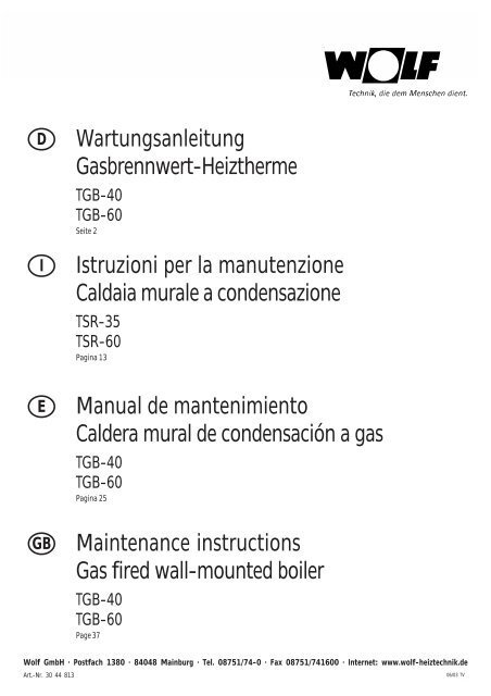
<strong>Wartungsanleitung</strong><br />
Gasbrennwert-Heiztherme<br />
<strong>TGB</strong>-<strong>40</strong><br />
<strong>TGB</strong>-<strong>60</strong><br />
Seite 2<br />
Istruzioni per la manutenzione<br />
Caldaia murale a condensazione<br />
TSR-35<br />
TSR-<strong>60</strong><br />
Pagina 13<br />
Manual de mantenimiento<br />
Caldera mural de condensación a gas<br />
<strong>TGB</strong>-<strong>40</strong><br />
<strong>TGB</strong>-<strong>60</strong><br />
Pagina 25<br />
Maintenance instructions<br />
Gas fired wall-mounted boiler<br />
<strong>TGB</strong>-<strong>40</strong><br />
<strong>TGB</strong>-<strong>60</strong><br />
Page 37<br />
Wolf GmbH · Postfach 1380 · 8<strong>40</strong>48 Mainburg · Tel. 08751/74-0 · Fax 08751/741<strong>60</strong>0 · Internet: www.wolf-heiztechnik.de<br />
Art.-Nr. 30 44 813<br />
06/03 TV
<strong>TGB</strong>-<strong>40</strong>/<strong>60</strong> <strong>Wartungsanleitung</strong><br />
Achtung<br />
Dichtungen nicht dehnen!<br />
Bild: Dichtungen nicht dehnen<br />
Allgemeine Hinweise<br />
Alle Wartungsarbeiten dürfen nur von einem Fachhandwerker<br />
durchgeführt werden.<br />
Regelmäßige Wartung sowie die ausschließliche Verwendung<br />
von Original Wolf-Ersatzteilen sind für einen störungsfreien<br />
Betrieb und lange Lebensdauer Ihres Gerätes<br />
von entscheidender Bedeutung.<br />
Wir empfehlen daher, einen Wartungsvertrag mit Ihrer<br />
Fachhandwerkerfirma abzuschließen.<br />
2
<strong>TGB</strong>-<strong>40</strong>/<strong>60</strong> <strong>Wartungsanleitung</strong><br />
Sicherheitshinweise<br />
Bevor Sie mit den Wartungsarbeiten beginnen, führen Sie<br />
folgende Arbeitsschritte durch:<br />
• Betriebsschalter an der Wolf-Gastherme ausschalten.<br />
An den Netzanschlußklemmen des Gerätes<br />
liegt auch bei ausgeschaltetem Betriebsschalter<br />
elektrische Spannung an.<br />
• Heizungsnotschalter (oder Sicherung) ausschalten.<br />
Betriebsschalter<br />
Bild: Gesamtansicht Regelung<br />
• Gasabsperrhahn schließen.<br />
• Absperrventile am Heizungsvor- und -rücklauf<br />
schließen und Wasser aus dem Gerät ablassen.<br />
• Frontverkleidung abnehmen und so abstellen, daß sie<br />
vor Beschädigung geschützt ist.<br />
Verbrennungsgefahr<br />
Verschiedene Bauteile können sehr heiß sein. Abkühlen<br />
lassen oder Handschuhe anziehen.<br />
Demontage der Brennkammereinheit<br />
2 x Spannverschlüsse oben<br />
• Brennraumgehäuse nach Lösen der Spannverschlüsse<br />
abnehmen.<br />
Brennraumgehäuse 2 x Spannverschlüsse unten<br />
Bild: Gasbrennwertgerät mit abgenommer Frontverkleidung<br />
3
<strong>TGB</strong>-<strong>40</strong>/<strong>60</strong> <strong>Wartungsanleitung</strong><br />
• Steckverbindungen an folgenden Bauteilen abziehen:<br />
Zündung, Ionisation, Erdung, Vor- Rücklauftemperaturfühler,<br />
Abgastemperaturfühler und Gasgebläse.<br />
Schlauch von der Mischkammer abziehen.<br />
Stecker Gasgebläse<br />
Mischkammer<br />
Stecker<br />
Vorlauffühler<br />
Stecker Zündung<br />
Stecker Ionisation<br />
Stecker Erdung<br />
Stecker<br />
Abgasfühler<br />
Stecker<br />
Rücklauffühler<br />
Bild: Gasbrennwertgerät mit abgenommem Brennraumgehäuse<br />
• Strahlungsblech nach vorn ziehen und Strahlungsblech<br />
aushängen.<br />
• Verschraubung Gasanschluß Mischkammer lösen<br />
Bild: Strahlungsblech<br />
Strahlungsblech<br />
• Muttern (3 Stück) am Brennerflansch lösen<br />
Verschraubung Gasanschluß Mischkammer<br />
Bild: Verschraubung Gasanschluß Mischkammer<br />
• Gesamte Einheit (Mischkammer, Ventilator und Brennerflansch)<br />
abnehmen.<br />
Mutter am Brennerflansch<br />
4<br />
Bild: Mutter am Brennerflansch
<strong>TGB</strong>-<strong>40</strong>/<strong>60</strong> <strong>Wartungsanleitung</strong><br />
• Überwurfmutter des Entlüfterrohrs zum Schnellentlüfter<br />
lösen und Entlüfterrohr samt Schnellentlüfter nach oben<br />
herausnehmen<br />
• Schraube Deckel/Rückwand lösen<br />
• Verschraubungen Vor- / Rücklauf lösen<br />
Überwurfmutter zum Entlüfterrohr<br />
Schraube Deckel Rückwand<br />
Bild: Überwurfmutter / Deckel / Rückwand<br />
Verschraubung Vorlauf<br />
Verschraubung Rücklauf<br />
Bild: Verschraubungen<br />
• Gerätesiphon abschrauben.<br />
Bei einigen Geräten muß dafür das Sicherungsblech<br />
entfernt werden. Siphon entleeren und abgelagerte Partikel<br />
ausspülen.<br />
Bild: Gerätesiphon<br />
Gerätesiphon<br />
• Schiebestück am Abgasrohr nach oben schieben.<br />
Bei einigen Geräten ist dafür eine Schlauchschelle zu<br />
lösen, bei anderen eine Blattfeder hinter dem Differenzdruckwächter<br />
zur Seite zu drücken.<br />
Bild: Blattfeder<br />
Bild: Schiebestück<br />
5
<strong>TGB</strong>-<strong>40</strong>/<strong>60</strong> <strong>Wartungsanleitung</strong><br />
• Komplette Brennkammereinheit anheben bis der<br />
Kondensatablaufstutzen frei ist und Brennkammereinheit<br />
nach vorne herausnehmen.<br />
• Es ist vorteilhaft, diese Einheit auf einem Eimer abzusetzen.<br />
Brennkammereinheit<br />
Bild: Brennkammereinheit<br />
• Brenner nach oben herausnehmen<br />
Bild: Brennkammereinheit auf Eimer abgesetzt<br />
Bild: Brenner nach oben herausnehmen<br />
• Gewindestangen des Brennkammerdeckels lösen (4Stück)<br />
und herausziehen<br />
Gewindestange<br />
6<br />
Bild: Gewindestange des Brennkammerdeckels
<strong>TGB</strong>-<strong>40</strong>/<strong>60</strong> <strong>Wartungsanleitung</strong><br />
• Brennkammerdeckel mit Schraubendreher von der<br />
Brennkammer lösen.<br />
Bild: Deckel von der Brennkammer lösen<br />
• Brennkammerdeckel abnehmen.<br />
Achtung: Nicht verkanten, da sonst die Isolierung zerstört<br />
werden kann.<br />
Brennkammerdeckel<br />
Bild: Brennkammerdeckel<br />
• Wärmetauscher mit Schraubendreher von der<br />
Kondensatwanne lösen<br />
Bild: Wärmetauscher von der Kondensatwanne lösen<br />
• Wärmetauscher nach oben abnehmen<br />
Bild: Wärmetauscher nach oben abnehmen<br />
7
<strong>TGB</strong>-<strong>40</strong>/<strong>60</strong> <strong>Wartungsanleitung</strong><br />
• Mutter im Brennkammertopf lösen, ggf. an der Schraube<br />
gegenhalten.<br />
Brennkammertopf<br />
Bild: Brennkammertopf im Heizwasserwärmetauscher<br />
• Topf herausziehen<br />
Bild: Topf herausziehen<br />
• Mit Hilfe des Brenners die Isolierung von unten nach<br />
oben herausdrücken.<br />
Hierzu Wärmetauscher umgedreht auf den Boden stellen<br />
und von oben vorsichtig durchdrücken.<br />
Bild: Isolierung mit Brenner herausdrücken<br />
8<br />
Bild: 2-teilige Isolierung aus dem Wärmetauscher<br />
gedrückt
<strong>TGB</strong>-<strong>40</strong>/<strong>60</strong> <strong>Wartungsanleitung</strong><br />
• Verbrennungsrückstände mit Wolf Reinigungsbürste<br />
Art.-Nr. 24 <strong>40</strong> 053 vom Wärmetauscher entfernen.<br />
• Bei stärkerer Verschmutzung Heizwasserwärmetauscher<br />
mit Fauch <strong>60</strong>0, Fauch 610, Sotin 230 (230 GA), DC 35/3<br />
H von Thermochema oder einem gleichwertigen Mittel<br />
reinigen und mit klarem Wasser nachspülen.<br />
• Bei Bedarf Brenner mit einer Bürste reinigen.<br />
Bild: Wärmetauscher reinigen<br />
• Kondensatwanne säubern<br />
Zusammenbau<br />
Bild: Brenner reinigen<br />
• Der Zusammenbau erfolgt in umgekehrter Reihenfolge<br />
der Demontage.<br />
Achtung:<br />
Grundsätzlich sind alle Dichtungen an wasserund<br />
abgasführenden Bauteilen, die getrennt<br />
wurden, auszutauschen und vor dem Zusammenbau<br />
mit Silikonfett (andere Fette zerstören<br />
die Dichtungen) einzustreichen.<br />
Bild: Alle Dichtungen mit Silikon einfetten.<br />
• Brennkammertopf zusammenbauen. Die weiche gelochte<br />
Isolierung befindet sich zwischen Topf und fester<br />
Isolierung.<br />
Bild: Aufbau Brennkammertopf<br />
9
<strong>TGB</strong>-<strong>40</strong>/<strong>60</strong> <strong>Wartungsanleitung</strong><br />
• Brennkammertopf von unten einschieben.<br />
Position siehe oberstes Bild auf Seite 8.<br />
Etwas weniger einschieben ist vorteilhaft. Die genaue<br />
Position ergibt sich beim Einbau des Wärmetauschers in<br />
die Kondensatwanne. Wird der Topf zu weit eingeschoben,<br />
läßt sich später der Brenner nicht ganz einschieben.<br />
• Beim Zusammenbau auf richtige Position der<br />
Brennkammereinheit zur Kondensatwanne achten.<br />
(Befestigungsstange hinten rechts läuft im U-Profil)<br />
Bild: Brennkammertopf von unten in den Wärmetauscher<br />
einführen<br />
• Dichtschnur und Deckelblech auf den Wärmetauscher<br />
legen. (Bis Herst-Nr. 0292... ist dieses Deckelblech nicht<br />
vorhanden, bis Herst-Nr. 0143... ist die Dichtschnur<br />
nicht vorhanden). Bei der Wartung ist auch bei älteren<br />
Geräten Dichtschnur und Deckelblech nachzurüsten.<br />
• Wenn die BK-Isolierung beim Ausbau beschädigt worden<br />
ist, muß diese gegen eine neue ersetzt werden<br />
(Isolierung Brennkammerdeckel und Deckelblech, Art-<br />
Nr. 86 02 684)<br />
Brennkammereinheit Kondensatwanne<br />
Bild: Position Brennkammereinheit / Kondensatwanne<br />
Bild: Deckelblech auf Wärmetauscher legen<br />
•Position Brennkammerdeckel siehe Bild.<br />
Achtung:<br />
Bei Einbau des Brenners ist darauf zu achten,<br />
daß der Brennerflansch auf dem Brennkammerdeckel<br />
aufliegt, andernfalls ist der<br />
Brennkammertopf zu weit oben.<br />
10<br />
Bild: Position Brennkammerdeckel
• Beim Zusammenbau ist besonders darauf zu achten, daß<br />
- das Abgasrohr bis zum Anschlag in der Kondensatwanne<br />
steckt<br />
- die pneumatischen Steuerleitungen gemäß neben<br />
stehendem Bild angeschlossen sind<br />
- die Elektrodenstecker gemäß nebenstehendem Bild<br />
aufgesteckt sind.<br />
<strong>TGB</strong>-<strong>40</strong>/<strong>60</strong> <strong>Wartungsanleitung</strong><br />
Bild: Position pneumatische Steuerleitungen<br />
Sicherheitshinweise<br />
Nach Abschluß der Wartungsarbeiten, führen Sie folgende<br />
Arbeitsschritte durch:<br />
• Siphon wieder befüllen, montieren und auf festen Sitz<br />
an der Kondensatwanne prüfen.<br />
• Absperrventil am Heizungsvor- und -rücklauf öffnen.<br />
Kaltwasserzulauf öffnen.<br />
• Füllen Sie, falls erforderlich, die Heizungsanlage wieder<br />
auf ca. 1,5 bar auf, und entlüften Sie die Heizungsanlage.<br />
• Gasabsperrhahn öffnen.<br />
• Heizungsnotschalter (oder Sicherung) einschalten.<br />
• Betriebsschalter an der Wolf-Gastherme einschalten.<br />
• Überprüfen Sie das Gerät auf gas- und wasserseitige<br />
Dichtheit.<br />
• Überprüfen Sie die einwandfreie Funktion und die<br />
Abgaswerte des Gerätes.<br />
• Hängen Sie die Frontverkleidung ein.<br />
Bild: Elektrodenstecker<br />
Bild: Steuerleitung zum Ventilator<br />
Bild: Versorgungsleitung und Erdung zum Ventilator<br />
11
<strong>TGB</strong>-<strong>40</strong>/<strong>60</strong> <strong>Wartungsanleitung</strong><br />
Übersicht der Arbeitsschritte mit Wartungsprotokoll<br />
Nr. Arbeitsschritt Protokollpunkt<br />
1 Gerät ausschalten, Notschalter aus<br />
2 Gaszufuhr schließen,<br />
3 Wartungshähne schließen und Wasser ablassen<br />
4 Verkleidung und Brennraumgehäuse abnehmen<br />
5 Elektrische Verbindungen an Ventilator, Fühlern<br />
und Elektroden öffnen<br />
6 Strahlungsblech/Mischkammer/Ventilator/<br />
Brennerflansch ausbauen<br />
7 Siphon abnehmen und reinigen O<br />
8 Brenner ausbauen, bei Bedarf reinigen O<br />
9 Heizwasserwärmetauscher ausbauen / reinigen O<br />
10 Kondensatwanne reinigen O<br />
11 Mischkammer bei Bedarf reinigen O<br />
12 Überwachungselektrode wechseln O<br />
13 Dichtungen wechseln und mit Silkonfett einschmieren O<br />
14 Gerät zusammenbauen<br />
15 Siphon füllen, montieren und auf festen Sitz achten O<br />
16 Gerät auf 1,5 - 2,5 bar füllen und entlüften O<br />
17 Gaszufuhr öffnen, Gerät einschalten<br />
18 Dichtheitskontrolle Hydraulik O<br />
19 Dichtheitskontrolle Gas O<br />
20 Dichtheitskontrolle Abgassystem O<br />
21 Zündung prüfen O<br />
22 Zusammenspiel mit Regelungszubehör prüfen O<br />
23 Abgassmessung bei Kaminkehrerbetrieb O<br />
24 Abgastemperatur brutto °C<br />
25 Ansauglufttemperatur °C<br />
26 Abgastemperatur netto °C<br />
27 Kohlendioxidgehalt (CO2) %<br />
28 oder Sauerstoffgehalt (O2) %<br />
29 Kohlenmonoxydgehalt (CO) %<br />
30 Abgasverlust %<br />
Wartung bestätigen (Firmenstempel, Unterschrift)<br />
Datum<br />
12
Istruzioni per la manutenzione<br />
Caldaia murale a condensazione<br />
TSR-35<br />
TSR-<strong>60</strong><br />
Wolf GmbH · Postfach 1380 · 8<strong>40</strong>48 Mainburg · Tel. 08751/74-0 · Fax 08751/741<strong>60</strong>0 · Internet: www.wolf-heiztechnik.de<br />
Kaiser S.p.A. · Via S. Domenico, 107 · 50133 Firenze · Tel. 055-576703 · Fax 055-587737· Internet: www.kaiser.it<br />
13
TSR-35/<strong>60</strong> Istruzioni per la manutenzione<br />
Attenzione<br />
Non allungare le guarnizioni!<br />
Figura: non allungare le guarnizioni<br />
Avvertenze generali<br />
Tutti i lavori di manutenzione ordinaria e straordinaria<br />
devono essere eseguiti soltanto da parte di un tecnico<br />
specializzato.<br />
La manutenzione regolare così come anche l‘utilizzo di<br />
ricambi originali Wolf sono di fondamentale importanza<br />
per il corretto funzionamento e per una lunga durata del<br />
vostro apparecchio.<br />
Consigliamo vivamente di stipulare un contratto di<br />
manutenzione con il Centro di Assistenza Autorizzato.<br />
14
TSR-35/<strong>60</strong> Istruzioni per la manutenzione<br />
Avvertenze per la sicurezza<br />
Prima di iniziare con la manutenzione devono essere<br />
effettuati i seguenti lavori:<br />
• Spegnere l‘interruttore generale della caldaia murale a<br />
condensazione Wolf.<br />
Sui morsetti per il collegamento di rete<br />
dell‘apparrecchio c‘è tensione anche con<br />
l‘interruttore spento.<br />
• Spegnere l‘interruttore d‘emergenza della caldaia (oppure<br />
il fusibile).<br />
L‘interruttore generale<br />
Figura: Veduta complessiva regolazione<br />
• Chiudere il rubinetto del gas.<br />
• Chiudere le valvole d‘intercettazione della mandata e<br />
del ritorno della caldaia e svuotare il circuito idraulico<br />
della caldaia.<br />
• Togliere il mantello frontale e disporrlo in modo che sia<br />
protetto da eventuali danneggiamenti.<br />
Pericolo di ustioni<br />
Alcuni componenti possono essere molto caldi. Lasciarli<br />
raffreddare oppure utilizzare dei guanti.<br />
Smontaggio della camera stagna<br />
2 x ganci ad innesto superiori<br />
• Togliere il mantello della camera di combustione dopo<br />
aver tolto i ganci ad innesto.<br />
camera di combustione<br />
2 x ganci ad innesto inferiori<br />
Figura: Caldaia senza mantello frontale<br />
15
TSR-35/<strong>60</strong> Istruzioni per la manutenzione<br />
• Togliere i connettori dai seguenti componenti:<br />
accensione, ionizzazione, messa a terra, sonde di mandata<br />
e di ritorno, sonda temperatura fumi e ventilatore fumi.<br />
Togliere il tubo flessibile dalla camera di miscelazione.<br />
Connettore<br />
ventilatore fumi<br />
Camera di<br />
miscelazione<br />
Connettore<br />
sonda mandata<br />
Connettori<br />
accensione,<br />
ionizzazione,<br />
messa a terra<br />
Connettore<br />
sonda fumi<br />
Connettore<br />
sonda ritorno<br />
Figura: Caldaia murale a condensazione con camera stagna smontata<br />
• Tirare la lamiera per protezione al calore verso l‘avanti<br />
ed estrarre la lamiera (attenzione fa una corte resistenza).<br />
Lamiera per protezione al calore<br />
• Svitare il dado raccordo gas della camera di miscelazione<br />
(attenzione alla guarnizione gas).<br />
Figura: Lamiera per protezione al calore<br />
• Svitare i dadi (3 pezzi) dalla flangia bruciatore<br />
Collegamento a vite raccordo gas camera misc.<br />
Figura: Collegamento a vite raccordo gas camera di miscelazione<br />
• Togliere l‘unità completa (camera di miscelazione,<br />
ventilatore fumi e flangia bruciatore).<br />
Dado flangia bruciatore<br />
16<br />
Figura: Dado flangia bruciatore
TSR-35/<strong>60</strong> Istruzioni per la manutenzione<br />
• Svitare il dado del tubo di collegamento del disaeratore<br />
rapido ed estrarre il tubo con il disaeratore verso l‘alto.<br />
• Svitare la vite coperchio/retro<br />
Dado tubo di collegamento disaeratore rapido<br />
Vite coperchio/retro<br />
Figura: Dado / coperchio / retro<br />
• Svitare i raccordi mandata/ritorno (attenzione ad<br />
eventuali residui dell‘acqua impianto riscaldamento)<br />
Vite mandata<br />
Vite ritorno<br />
Figura: Raccordi<br />
• Svitare il sifone della caldaia.<br />
Con alcune caldaie è necessario togliere la lamiera di<br />
sicurezza. Svuotare il sifone e sciaquare eventuali residui.<br />
Sifone<br />
Figura: Sifone<br />
• Spingere il pezzo scorrevole del tubo fumi verso l‘alto.<br />
Con alcuni apparecchi è necessario svitare una fascetta<br />
per tubi flessibili, con altri apparecchi invece deve<br />
essere premuta una molla a balestra sul retro del<br />
pressostato verso la parte laterale.<br />
Figura: Molla a balestra<br />
Figura: Pezzo scorrevole<br />
17
TSR-35/<strong>60</strong> Istruzioni per la manutenzione<br />
• Sollevare l‘unità completa della camera di combustione<br />
finchè non si sia liberato il raccordo scarico condensa ed<br />
estrarrla verso avanti.<br />
• Consigliamo di appoggiare quest‘unità su un secchio<br />
oppure oggetto analogo.<br />
Unità camera di combustione<br />
Figura: Unità camera di combustione<br />
• Estrarre il bruciatore verso l‘alto<br />
Fig.: Unità camera combustione appogiata sul secchio<br />
Fig.: Estrarre il bruciatore verso l‘alto<br />
• Svitare le barre filettate del coperchio della camera di<br />
combustione (4 pezzi) e togliere il coperchio stesso.<br />
Barra filettata<br />
18<br />
Fig.: Barra filettata coperchio camera di combustione
TSR-35/<strong>60</strong> Istruzioni per la manutenzione<br />
• Togliere il coperchio della camera di combustione dalla<br />
camera di combustione utilizzando un cacciavite.<br />
Figura: Togliere il coperchio dalla camera di combustione<br />
• Togliere il coperchio.<br />
Attenzione: Non inclinare per evitare il danneggiamento<br />
dell‘isolamento.<br />
Coperchio camera di combustione<br />
Figura: Coperchio camera di combustione<br />
• Togliere lo scambiatore primario dal collettore di<br />
condensa utilizzando un cacciavite<br />
Figura: Togliere lo scambiatore primario dal collettore di<br />
condensa<br />
• Estrarre lo scambiatore primario verso l‘alto<br />
Figura: Estrarre lo scambiatore primario verso l‘alto<br />
19
TSR-35/<strong>60</strong> Istruzioni per la manutenzione<br />
• Togliere il dado del tampone della camera di combustione,<br />
eventualmente tenere contro sulla vite.<br />
Tampone camera<br />
di combustione<br />
Figura: Tampone della camera di combustione nello<br />
scambiatore primario<br />
• Estrarre il tampone dalla camera di combustione<br />
Figura: Estrarre il tampone<br />
• Premere l‘isolamento dal basso verso l‘alto con il<br />
bruciatore oppure con il tampone stesso.<br />
Per eseguire quest‘operazione, appoggiare lo scambiatore<br />
primario per terra e premere cautamente dall‘alto<br />
(attenzione a manipolare il refrattario).<br />
Figura: Spingere l‘isolamento col bruciatore<br />
20<br />
Figura: L‘isolamento a due parti spinto fuori dallo<br />
scambiatore primario
TSR-35/<strong>60</strong> Istruzioni per la manutenzione<br />
• Rimuovere gli eventuali residui di combustione dallo<br />
scambiatore utilizzando l’apposita spazzola (codice Wolf<br />
24 <strong>40</strong> 053).<br />
• In caso di sporco più pesante, lavare lo scambiatore<br />
primario con Fauch <strong>60</strong>0, Fauch 610, Sotin 230 (230 GA),<br />
DC 35/3 H di Thermochema oppure con un liquido<br />
equivalente e risciacquare con acqua corrente.<br />
• Se fosse necessario, pulire il bruciatore con una spazzola.<br />
Figura: Pulizia dallo scambiatore primario<br />
• Pulire il collettore della condensa<br />
Figura: Pulizia dal bruciatore<br />
Montaggio<br />
• Il montaggio avviene procedendo al contrario dello<br />
smontaggio.<br />
Attenzione:In generale, tutte le guarnizioni a contatto<br />
con acqua e fumi che sono state tolte,<br />
devono essere sostituite e prima del<br />
montaggio vanno lubrificate con grasso<br />
siliconico (altri tipi di grassi danneggiano le<br />
guarnizioni).<br />
Figura: Ingrassare tutte le guarnizioni con il silicone<br />
• Rimontare il tampone della camera di combustione.<br />
L‘isolamento morbido, perforato si trova tra il tampone<br />
e l‘isolamento fisso.<br />
Figura: Montaggio tampone camera di combustione<br />
21
TSR-35/<strong>60</strong> Istruzioni per la manutenzione<br />
• Inserire il tampone della camera di combustione dal<br />
basso.<br />
Per il posizionamento vedi la figura superiore della<br />
pagina 8.<br />
Consigliamo l‘inserimento non completo. La posizione<br />
precisa risulta dal montaggio dallo scambiatore primario<br />
nel collettore di condensa. Se il tampone viene spinto<br />
troppo verso l‘interno, il successivo inserimento completo<br />
del bruciatore non sarà possibile.<br />
• Fare attenzione alla corretta posizione dall‘unita della<br />
camera di combustione rispetto al collettore di condensa<br />
(la barra filettata sul retro lato destro deve essere posata<br />
a profilo ad U).<br />
Figura: Inserimento dal basso del tampone della camera di<br />
combustione nello scambiatore primario<br />
• Posizionare la corda e la copertura in lamiera sullo<br />
scambiatore (fino al numero di matricola 0292 ... la<br />
copertura non è prevista, fino al numero di matricola<br />
0143 ... non è prevista la corda). Durante la manutenzione<br />
anche gli apparecchi meno recenti devono essere<br />
equipaggiati con corda e copertura in lamiera.<br />
• Se l‘isolamento della camera di combustione è stato<br />
danneggiato durante lo smontaggio, lo stesso isolamento<br />
deve essere sostituito con uno nuovo. (Isolamento<br />
coperchio camera di combustione e relativa lamiera,<br />
codice 86 02 684)<br />
Unità camera di combustione<br />
Collettore di<br />
condensa<br />
Fig.: Posizionamento unità camera di combustione/<br />
collettore di condensa<br />
Figura: Appoggiare la corda e la lamiera del coperchio<br />
sullo scambiatore primario<br />
• Per il posizionamento della camera di combustione vedi<br />
la relativa figura.<br />
Attenzione: Durante il montaggio del bruciatore,<br />
fare attenzione ad appoggiare la flangia<br />
del bruciatore sul coperchio della camera<br />
di combustione, in caso contrario, il<br />
tampone rimane troppo in alto.<br />
22<br />
Figura: Posizonamento coperchio camera di combustione
TSR-35/<strong>60</strong> Istruzioni per la manutenzione<br />
• Durante il montaggio, fare particolare attenzione a<br />
quanto segue:<br />
- il tubo fumi deve essere inserito nel collettore<br />
della condensa fino all‘arresto<br />
- le linee di comando pneumatiche devono<br />
essere collegate secondo la figura riportata<br />
sulla destra<br />
- i connettori degli elettrodi devono essere<br />
collegati secondo la figura riportata sulla destra<br />
Avvertenze di sicurezza<br />
Dopo aver eseguito i lavori di manutenzione, devono<br />
essere effettuate le seguenti operazioni:<br />
• Ricaricare il sifone e controllare la tenuta sul collettore<br />
della condensa.<br />
• Aprire la valvola d‘intercettazione sulla mandata e sul<br />
ritorno della caldaia. Aprire il rubinetto dell‘acqua<br />
fredda.<br />
• Se necessario, ricaricare l‘impianto di riscaldamento<br />
fino al raggiungimento di una pressione di 1,5 bar e<br />
disaerare lo stesso impianto.<br />
• Aprire il rubinetto del gas.<br />
• Inserire l‘interruttore d‘emergenza della caldaia (oppure<br />
il fusibile).<br />
• Accendere l‘interruttore generale della caldaia a<br />
condensazione Wolf.<br />
• Controllare la tenuta dell‘apparecchio sul lato fumi e<br />
lato acqua.<br />
• Controllare il perfetto funzionamento ed effettuare<br />
l‘analisi di combustione dell‘apparecchio.<br />
• Inserire il frontale della caldaia.<br />
Figura: posizionamento linee di comando<br />
pneumatiche<br />
Figura: connettori elettrodi<br />
Figura: Linea di comando al ventilatore<br />
Figura: Linea d‘alimentazione e messa a terra al<br />
ventilatore<br />
23
TSR-35/<strong>60</strong> Istruzioni per la manutenzione<br />
Veduta complessiva delle operazioni con protocollo di manutenzione<br />
N° Operazione Punto protocollo<br />
1 Spegnere l‘apparecchio e l‘interrruttore d‘emergenza<br />
2 Chiudere il rubinetto del gas<br />
3 Chiudere i rubinetti di manutenzione e scaricare l‘acqua<br />
4 Togliere il mantello ed il rivestimento della camera di combustione<br />
5 Aprire i connettori elettrici sul ventilatore e sulle sonde,<br />
aprire gli elettrodi<br />
6 Smontare la lamiera per la protezione al calore/la camera di miscelazione/<br />
il ventilatore e la flangia bruciatore<br />
7 Togliere il sifone e pulirlo O<br />
8 Smontare il bruciatore, se necessario lavarlo O<br />
9 Smontare lo scambiatore primario / lavarlo O<br />
10 Pulire il collettore della condensa O<br />
11 Se necessario pulire la camera di miscelazione O<br />
12 Sostituire l‘elettrodo di rilevazione O<br />
13 Sostituire le guarnizioni e lubrificare con il grasso siliconico O<br />
14 Montare l‘apparecchio<br />
15 Caricare il sifone e verificare la perfetta tenuta O<br />
16 Caricare l‘apparecchio a 1,5 - 2,5 bar e disaerarlo O<br />
17 Aprire il rubinetto del gas, accendere l‘apparrecchio<br />
18 Controllo di tenuta parti idraulici O<br />
19 Controllo di tenuta lato gas O<br />
20 Controllo di tenuta sistema scarico fumi O<br />
21 Controllare l‘accensione O<br />
22 Controllare il funzionamento con gli accessori di regolazione O<br />
23 Controllo fumi durante l‘intervento dello spazzacamino O<br />
24 Temperatura fumi lorda °C<br />
25 Temperatura aria aspirata °C<br />
26 Temperatura fumi netta °C<br />
27 Contenuto anidride carbonica (CO2) %<br />
28 oppure contenuto ossigeno (O2) %<br />
29 Contenuto ossido di carbonio (CO) %<br />
30 Perdite fumi %<br />
Conferma manutenzione (timbro centro assistenza tecnica, firma)<br />
24<br />
Data
Manual de mantenimiento<br />
Caldera mural de condensación a gas<br />
<strong>TGB</strong>-<strong>40</strong><br />
<strong>TGB</strong>-<strong>60</strong><br />
25
<strong>TGB</strong>-<strong>40</strong>/<strong>60</strong> Instrucciones de mantenimiento<br />
Atención<br />
No tensar las juntas!<br />
Fig: No tensar las juntas<br />
Indicaciones generales<br />
Todos las tareas de mantenimiento sólo pueden ser<br />
realizadas por personal profesional cualificado y<br />
autorizado.<br />
El mantenimiento regular y la utilización exlusiva de<br />
piezas de repuestos originales Wolf son de gran<br />
importancia para el funcionamiento correcto y la larga<br />
vida útil del aparato.<br />
Recomendamos la firma de un contrato de mantenimiento<br />
con una empresa mantenedora de su confianza<br />
26
<strong>TGB</strong>-<strong>40</strong>/<strong>60</strong> Instrucciones de mantenimiento<br />
Indicaciones de seguridad<br />
Antes de comenzar las tareas de mantenimiento realicen<br />
los siguientes pasos de trabajo:<br />
• Desconecte la caldera mediante el interruptor principal<br />
de su caldera.<br />
Las clemas de alimentación eléctrica se<br />
mantendran aun desconectado el interruptor<br />
con tensión.<br />
Interruptor general<br />
Fig: Vista general regulación<br />
• Desconectar la instalación mediante el interruptor de<br />
emergencia o térmico.<br />
• Cierre la llave de paso de gas<br />
• Cierre las llaves de paso de impulsión y retorno de la<br />
instalación de calefacción y vacíe el agua de la<br />
caldera<br />
• Desmonte la carcasa frontal y depositela en lugar que<br />
no pueda dañarse.<br />
Peligro de quemadura<br />
Diferentes piezas pueden estar muy calientes. Deje que se<br />
enfrie o pongase guantes<br />
2 x Tensores superiores<br />
Desmontaje de la unidad de la cámara de<br />
combustión<br />
• Una vez sueltas los tensores de la tapa desmontarla.<br />
Tapa de la camara de<br />
combustión<br />
2 x Tensores inferiores<br />
Fir: Caldera mural sin tapa frontal<br />
27
<strong>TGB</strong>-<strong>40</strong>/<strong>60</strong> Instrucciones de mantenimiento<br />
• Desconectar las uniones eléctricas de los siguientes<br />
elementos:<br />
Encendido, Ionisación, tierra , sonda de impulsión y<br />
retorno, sonda de humos y ventilador.<br />
Retirar el tubito de silicona de la cámara de mezcla.<br />
Conector<br />
ventilador<br />
Cámara de mezcla<br />
Conector<br />
sonda<br />
impulsión<br />
Conector<br />
sonda humos<br />
Conector<br />
encendido<br />
Conector<br />
ionización<br />
Conector tierra<br />
Conector<br />
sonda retorno<br />
Fig: Caldera mural sin tapa de cámara de combustión<br />
• Tirar de la placa trasera hacia adelante y descolgarla para<br />
retirar.<br />
Fig: Placa trasera<br />
Placa trasera<br />
• Aflojar la unión roscada de la conexión de gas a la<br />
cámara de mezcla<br />
Unión roscada de gas a cámara de mezcla<br />
Fig: Unión roscada de gas a cámara de mezcla<br />
• Retirar las tuercas (3 uds.) de la brida del quemador<br />
• Extraer la unidad completa ( Cámara de mezcla , ventilador<br />
y brida de quemador ).<br />
Tuercas de brida de quemador<br />
28<br />
Fig: Tuercas de brida de quemador
<strong>TGB</strong>-<strong>40</strong>/<strong>60</strong> Instrucciones de mantenimiento<br />
• Soltar el racor de la tuberia de purga al purgador<br />
automatico y retirarla hacia arriba junto con el purgador<br />
•Soltar tornillo placa trasera bastidor<br />
• Uniones de impulsión y retorno<br />
Racor hacia la tuberia de purga<br />
Tornillo Placa trasera bastidor<br />
Fig: Racor/Placa trasera bastidor<br />
Unión impulsión<br />
Unión retorno<br />
• Desenroscar sifón.<br />
Para realizar esta operación en algunos aparatos es<br />
necesario retirar una placa de seguridad.Vaciar el sifón<br />
y limpiar las particulas depositadas en el.<br />
Fig: Uniones imp. y ret.<br />
Sifón<br />
• Retirar hacia arriba la unión de salida de humos.<br />
Para realizar esta operación en algunos aparatos es<br />
necesario aflojar una brida. y en otros es necesario<br />
empujar/desplazar hacia un lado un muelle situado<br />
detras del presostato diferencial.<br />
Fig: Sifón<br />
Fig: Muelle<br />
Fig: Unión salida humos<br />
29
<strong>TGB</strong>-<strong>40</strong>/<strong>60</strong> Instrucciones de mantenimiento<br />
• Elevar la unidad completa de cámara de combustión<br />
hasta liberar la toma de evacuación de condensados y a<br />
continuación extraerla hacia adelante.<br />
• Se recomienda depósitar el cuerpo completo en un<br />
cubo.<br />
Unidad cámara combustión<br />
Fig: Unidad completa cámara de combustón<br />
• Extraer el quemador por arriba<br />
Bild: Unidad cámara combustión en el cubo<br />
Fig: Extraer quemador por arriba<br />
• Soltar las varillas roscadas (4 uds.) y retirarlas<br />
Varillas roscadas<br />
30<br />
Fig: Varilla roscada de la cámara de combustión
<strong>TGB</strong>-<strong>40</strong>/<strong>60</strong> Instrucciones de mantenimiento<br />
• Soltar la tapa de la cámara de combustón del hogar con<br />
un destornillador.<br />
Fig: Soltar tapa cámara , del hogar<br />
• Retirar tapa de cámara de combustión.<br />
Atención: No cantear , ya que se puede deteriorar el<br />
aislamiento<br />
Tapa cámara de combustión<br />
Fig: Tapa cámara de combustión<br />
• Soltar con un destornillador el intercambiador de la<br />
bandeja de condensados<br />
Fig: Soltar intercambiador de bandeja de condensados<br />
• Tirar del intercambiador hacía arriba<br />
Fig: Tirar del intercambiador hacía arriba<br />
31
<strong>TGB</strong>-<strong>40</strong>/<strong>60</strong> Instrucciones de mantenimiento<br />
• Aflojar tuerca del recipiente inferior del hogar .<br />
Recipiente<br />
inferior<br />
Fig:Recipiente inferior en el intercambiador<br />
• Extraer recipiente<br />
Fig : Extraer recipiente<br />
• Extraer con ayuda del quemador el aislamiento desde<br />
abajo hacia arriba.<br />
Para realizar esta operación situar el intercambiador al<br />
reves en el suelo y empujar con precaución hacia abajo.<br />
Fig: Expulsar aislamiento con quemador<br />
Fig: Aislamiento de 2 piezas fuera del intercambiador<br />
32
<strong>TGB</strong>-<strong>40</strong>/<strong>60</strong> Instrucciones de mantenimiento<br />
• Restos y suciedad producido por la combustión<br />
depositado en el intercambiador , limpiar con el cepillo<br />
de limpieza Wolf Ref.: 24 <strong>40</strong> 053.<br />
• En caso de gran suciedad limpiar con Fauch <strong>60</strong>0, Fauch<br />
610, Sotin 230 (230 GA), DC 35/3 H de Thermochema o<br />
con otro limpiador de igual composición luego enjuagar<br />
con agua clara.<br />
• En caso necesario limpiar con un cepillo.<br />
Fig: Limpiar intercambiador<br />
• Limpiar bandeja de condensados<br />
Montaje<br />
Bild:Limpiar quemador<br />
• El montaje se realiza en orden a la inversa al del<br />
desmontaje.<br />
Atención:Por norma general es obligatorio cambiar<br />
todas las juntas que esten montadas en<br />
elementos de conducción de agua ó productos<br />
de la combustión wurden que hayan sido<br />
separado.Una vez sustituidas se han de<br />
huntar con grasa de silicona.( otro tipo de<br />
grasas deterioran las juntas )<br />
Fig: Engrasar todas las juntas con silicona.<br />
• Montar el recipiente inferior de la cámara de<br />
combustión.El aislamiento agujereado se ha de montar<br />
entre el recipiente y el aislamiento compacto.<br />
Fig: Montaje del recipiente<br />
33
<strong>TGB</strong>-<strong>40</strong>/<strong>60</strong> Instrucciones de mantenimiento<br />
• Introducir el recipiente inferior por debajo en la cámara<br />
de combustión.<br />
Posición vease fig. en pag. 8<br />
No introducirlo del todo conlleva una pequeña ventaja.La<br />
posición exacta se consigue cuando se monta el<br />
intercambiador en la bandeja de condensados.En caso<br />
de introducir demasiado el recipiente inferior no permite<br />
situar de forma adecuada el quemador.<br />
• Durante el montaje verificar que se monta la unidad de<br />
cámara de combustión respecto a la bandeja de<br />
condensados en la posición correcta. (La varilla roscada<br />
trasera derecha pasa por la guía en U)<br />
Fig: Montar el recipiente inferior desde abajo en el<br />
intercambiador<br />
• Colocar el cordón de estanqueidad y la tapa encima del<br />
intercambiador (hasta nº de fab. 0292... no existe la tapa<br />
indicada , hasta nº de fab. 0143... no existe el cordón de<br />
estanqueidad). Durante el mantenimiento de aparatos<br />
mas antigüos sa ha de añadir la tapa y el cordón de<br />
estanqueidad.<br />
• En caso de que durante el desmontaje el aislamiento de<br />
la cámara de combustión haya sufrido deterioros, es<br />
necesario sustituirla por una nueva (Aislamiento,Tapa<br />
cámara de combustión y tapa, Nº de art. 86 02 684)<br />
Cámara de combustión Bandeja condensados<br />
Fig: Posición cámara de combustión /Bandeja<br />
condensados<br />
Fig: El cordón de estanqueidad y Tapa sobre intercambiador<br />
• Posición de la tapa vease Fig.<br />
Atención:<br />
Durante el montaje del quemador es importante<br />
tener en cuenta que la brida de<br />
quemador monte sobre la tapa de la cámara<br />
de combustión. Si no es así, el recipiente de<br />
la cámara de combustión esta situado<br />
demasiado arriba.<br />
34<br />
Fig: Posición Tapa cámara de combustión
<strong>TGB</strong>-<strong>40</strong>/<strong>60</strong> Instrucciones de mantenimiento<br />
• Durante el montaje se ha de tener en cuenta que<br />
- el tubo de salida de humos se ha introducido<br />
hasta el tope de la bandeja de condensados<br />
- los conductos neumaticos de regulación se<br />
conecten de manera correcta tal como se<br />
puede ver en la Fig.<br />
- los conectores eláctricos se conecten de<br />
manera corecta tal como se pude ver en la Fig.<br />
Indicaciones de seguridad<br />
Una vez terminado los trabajos de mantenimiento, realice<br />
los siguientes pasos :<br />
• Rellenar el sifón , montarlo y verificar que esta montado<br />
fijamente en la bandeja de condensados.<br />
• Abrir llaves de paso de impulsión y retorno de<br />
calefacción.Abris llave de paso entrada agua fría<br />
• LLenar en caso necesario la instalación de calefacción<br />
a aprox.1,5 bar luego purgar el sistema de calefacción<br />
• Abrir llave da paso de gas<br />
• Conectar interruptor general ó automético<br />
• Pulser el interruptor de encendido de la caldera mural<br />
Wolf.<br />
• Verificar estanqueidad del aparato en gas y agua.<br />
• Comprobar funcionamiento y valores de combustión<br />
del equipo<br />
• Montar la tapa frontal<br />
Fig: Posición conductos neumaticos de<br />
regulación<br />
Fig: Conectores de electrodos<br />
Fig: Conexiones de control al ventilador<br />
Fig: Conexiones de alimentación y tierra del ventilador<br />
35
<strong>TGB</strong>-<strong>40</strong>/<strong>60</strong> Instrucciones de mantenimiento<br />
Resumen de las tareas y protocolo de mantenimiento<br />
Nº. Tarea/paso de trabajo Punto de protocolo<br />
1 Apagar caldera , desconectar interruptor general<br />
2 Cerrar paso de gas,<br />
3 Cerrar llaves de paso y vaciar el agua de caldera<br />
4 Desmontar tapa y envolvente<br />
5 Desconectar todas las conexiones eléctricas de ventilador, sondas y abrir electrodos<br />
6 Desmontar chapa trasera/cámara de mezcla/ventilador y<br />
brida de quemador<br />
7 Retirar el sifón y limpiarlo O<br />
8 Desmontar quemador y limpiar en caso necesario O<br />
9 Desmontar y limpiar intercambiador primario O<br />
10 Limpiar bandeja de condensados O<br />
11 En caso necesario limpiar cámara de mezcla O<br />
12 Sustituir electrodo de ionización O<br />
13 Sustituir juntas y engrasar con grasa de silicaona O<br />
14 Montar el aparato<br />
15 Llenar , montar y verificar la fijación del sifón O<br />
16 Llenar la caldera hasta 1,5 - 2,5 bar y purgar O<br />
17 Abrir llave de gas y conectar la caldera<br />
18 Controlar estanqueidad hidráulica O<br />
19 Controlar estanqueidad de gas O<br />
20 Controlar estanqueidad sistema de evacuación de humos O<br />
21 Verificar encendido O<br />
22 Verificar funcionamiento caldera con accesorios de regulación O<br />
23 Analisis de combustión en pos. deshollinador O<br />
24 Temperatura de humos bruta °C<br />
25 Temperatura admisión de aire °C<br />
26 Temperatura de humos neta °C<br />
27 Contenido de CO2 %<br />
28 o contenido de óxigeno ( O2 ) %<br />
29 Contenido de monoxido de carbono ( CO ) %<br />
30 Pérdidas por humos %<br />
Confirmación de mantenimiento (Sello y firma)<br />
Fecha<br />
36
Maintenance instructions<br />
Gas fired wall-mounted boiler<br />
<strong>TGB</strong>-<strong>40</strong><br />
<strong>TGB</strong>-<strong>60</strong><br />
Wolf GmbH · Postfach 1380 · 8<strong>40</strong>48 Mainburg · Tel. +49-8751/74-0 · Fax +49-8751/741<strong>60</strong>0 · Internet: www.wolf-heiztechnik.de<br />
37
<strong>TGB</strong>-<strong>40</strong>/<strong>60</strong> Maintenance instructions<br />
Warning<br />
Do not stretch gaskets<br />
Do not stretch gaskets<br />
General notes<br />
Maintenance work must only be carried out by a qualified<br />
heating contractor.<br />
Regular maintenance and the exclusive use of original<br />
Wolf spare parts are necessary preconditions for troublefree<br />
operation and a long service life.<br />
We therefore recommend you arrange a maintenance<br />
contract with a local heating contractor.<br />
38
<strong>TGB</strong>-<strong>40</strong>/<strong>60</strong> Maintenance instructions<br />
Safety instructions<br />
Carry out the following steps before carrying out any<br />
maintenance work.<br />
• Switch OFF the system ON/OFF switch on the Wolf gas<br />
fired boiler.<br />
The mains terminals are ‘live‘ even when the<br />
ON/OFF switch has been switched OFF.<br />
• Switch OFF the emergency stop switch (or remove<br />
fuses).<br />
ON/OFF switch<br />
Control unit overview<br />
• Close the gas shut-off valve.<br />
• Close the shut-off valves on the heating flow and<br />
return, and drain the water from the boiler.<br />
• Remove the front panel and protect it from damage.<br />
Risk of burns<br />
Several components may be hot. Let these cool down or<br />
wear gloves.<br />
Dismantling the combustion chamber unit<br />
2 x top toggles<br />
• Remove the combustion chamber housing after releasing<br />
the toggles.<br />
Combustion chamber casing 2 x bottom toggles<br />
Gas fired condensing boiler with front casing removed<br />
39
<strong>TGB</strong>-<strong>40</strong>/<strong>60</strong> Maintenance instructions<br />
• Remove the plug connections from the following<br />
components: ignition, ionisation, earth, flow and return<br />
temperature sensor, flue gas temperature sensor and gas<br />
fan.<br />
Remove the hose from the mixing chamber.<br />
Gas fan plug<br />
Mixing chamber<br />
Flow sensor<br />
plug<br />
Flue gas<br />
sensor plug<br />
Ignition plug<br />
Ionisation plug<br />
Earth plug<br />
Return<br />
sensor plug<br />
Gas fired condensing boiler with combustion chamber<br />
housing removed<br />
• Pull the anti-radiation panel forward and unhook the<br />
panel.<br />
Anti-radiation panel<br />
Location of anti-radiation panel<br />
• Release the joint between the gas connection and the<br />
mixing chamber.<br />
Joint between the gas connection and mixing chamber<br />
Location of joint<br />
• Release the nuts (3 no.) on the burner flange.<br />
• Remove the whole assembly (mixing chamber, fan and<br />
burner flange).<br />
Nut on the burner flange<br />
<strong>40</strong><br />
Location of nut on the burner flange
<strong>TGB</strong>-<strong>40</strong>/<strong>60</strong> Maintenance instructions<br />
• Slacken the ventilation pipe union nut towards the quick<br />
acting air-vent valve and remove the whole quick acting<br />
vent valve upwards.<br />
• Undo screw from the lid/rear panel.<br />
Union nut for ventilation pipe<br />
Lid screw - rear panel<br />
• Release the flow and return compression fittings.<br />
Location of union nut / lid / rear panel<br />
Flow compression fitting<br />
Return compression fitting<br />
Location of compression fittings<br />
• Unscrew the boiler siphon.<br />
On some boilers the safety panel must first be removed.<br />
Drain the siphon and flush out any sediment.<br />
Boiler siphon<br />
• Push the flue pipe damper upwards.<br />
On some boilers a hose clip needs to be released first, on<br />
others simply push a leaf spring behind the differential<br />
pressure switch aside.<br />
Location of boiler siphon<br />
Leaf spring<br />
Flue pipe damper<br />
41
<strong>TGB</strong>-<strong>40</strong>/<strong>60</strong> Maintenance instructions<br />
• Lift the complete combustion chamber unit until the<br />
condensate drain connection is free, then remove the<br />
combustion chamber assembly towards the front.<br />
• We recommended you set this unit down on a bucket.<br />
Combustion chamber<br />
Combustion chamber assembly<br />
Set the combustion chamber unit onto a bucket<br />
• Remove the burner upwards.<br />
Remove the burner upwards<br />
• Release and remove the threaded rods of the combustion<br />
chamber lid (4 no.).<br />
Threaded rod<br />
42<br />
Location of combustion chamber lid threaded rods
<strong>TGB</strong>-<strong>40</strong>/<strong>60</strong> Maintenance instructions<br />
• Lever off the combustion chamber lid from the<br />
combustion chamber using a screwdriver.<br />
Releasing the lid from the combustion chamber<br />
• Remove the combustion chamber lid.<br />
Note: Ensure a level removal to prevent damaging<br />
the insulation.<br />
Combustion chamber lid<br />
Location of combustion chamber lid<br />
• Release the heat exchanger from the condensate pan<br />
using a screwdriver.<br />
Releasing heat exchanger from the condensate pan<br />
• Remove the heat exchanger upwards.<br />
Removing the heat exchanger upwards<br />
43
<strong>TGB</strong>-<strong>40</strong>/<strong>60</strong> Maintenance instructions<br />
• Release the nut inside the combustion chamber, if<br />
necessary counter-lock the screw.<br />
Combustion<br />
chamber pot<br />
Combustion chamber pot inside the heating water heat<br />
exchanger<br />
• Remove the pot.<br />
Remove the pot<br />
• With the burner, push the insulation from the bottom up<br />
and out.<br />
To do this, invert the heat exchanger on the floor and<br />
carefully push down from the top.<br />
Pushing out the insulation with the burner<br />
Two part insulation pushed out of the heat exchanger<br />
44
• Remove combustion residues from the heat exchanger<br />
using the Wolf cleaning brush part.no. 24 <strong>40</strong> 053.<br />
<strong>TGB</strong>-<strong>40</strong>/<strong>60</strong> Maintenance instructions<br />
• Clean severely contaminated heating water heat<br />
exchangers with Fauch <strong>60</strong>0, Fauch 610, Sotin 230 (230<br />
GA), DC 35/3 H by Thermochema or equivalent agent<br />
and flush with clear water.<br />
• If required, clean the burner with a brush.<br />
Cleaning the heat exchanger<br />
• Clean the condensate pan<br />
Assembly<br />
Cleaning the burner<br />
• Assemble in reverse order to the removal.<br />
Note:<br />
Generally replace all gaskets on water and<br />
flue gas components which have been<br />
separated and coat with silicon grease (other<br />
grease will destroy the gaskets) prior to<br />
reassembly.<br />
Lubricate all gaskets/seals with silicone<br />
• Assemble the combustion chamber pot. The soft<br />
perforated insulation fits between the pot and the<br />
permanently fitted insulation.<br />
Combustion chamber pot design<br />
45
<strong>TGB</strong>-<strong>40</strong>/<strong>60</strong> Maintenance instructions<br />
• Insert the combustion chamber pot from below.<br />
For position, see the top figure on page 8. It is not<br />
recommended to push the pot fully home. The precise<br />
position results during the installation of the heat<br />
exchanger into the condensate pan. The burner cannot<br />
be fully pushed home if the pot is pushed in too far.<br />
• During assembly observe the correct position of the<br />
combustion chamber assembly in relation to the<br />
condensate pan. (The rear r.h. fixing rod is located inside<br />
the channel section).<br />
Insert the combustion chamber pot from below into the<br />
heat exchanger<br />
• Locate the packing cord and the lid panel on the heat<br />
exchanger (up to serial no. 0292... the lid panel is not part<br />
of the assembly, up to serial no. 0143... the packing cord<br />
is not part of the assembly). During servicing, even on<br />
older units, the packing cord and the lid panel have to be<br />
fitted.<br />
• Should the combustion chamber insulation have been<br />
damaged during removal, replace it completely with<br />
new insulation (insulation for combustion chamber lid<br />
and lid panel, part no. 86 02 684).<br />
Combustion chamber assembly Condensate pan<br />
Location of combustion chamber assembly/condensate pan<br />
Locate the packing cord and the lid panel on the heat<br />
exchanger<br />
• For location of the combustion chamber lid see the<br />
adjacent illustration.<br />
Note:<br />
During the burner installation, note that the<br />
burner flange locates on the combustion<br />
chamber lid, otherwise the combustion<br />
chamber pot will be set too high.<br />
46<br />
Location of the combustion chamber pot
• During assembly, please note particularly, that:<br />
<strong>TGB</strong>-<strong>40</strong>/<strong>60</strong> Maintenance instructions<br />
- The flue pipe is inserted into the condensate pan<br />
until it bottoms out.<br />
- The pneumatic control cables are connected in<br />
accordance with the adjacent figure.<br />
- The electrode plug is connected in accordance with<br />
the adjacent figure.<br />
Pneumatic control cable position<br />
Safety instructions<br />
Carry out the following steps after completing the above<br />
maintenance work:<br />
• Refill the siphon, install and check for tightness against<br />
the condensate pan.<br />
• Open the shut-off valve on the heating flow and return.<br />
Open the cold water inlet.<br />
• Top up the heating system to approx. 1.5 bar, if necessary,<br />
and vent the entire heating system.<br />
• Open the gas shut-off valve.<br />
• Switch ON the emergency stop switch (or insert fuses).<br />
• Switch ON the system ON/OFF switch on the Wolf gas<br />
fired boiler.<br />
• Check the boiler for leaks at gas and water connections.<br />
• Check the boiler for perfect function and its flue gas<br />
values.<br />
• Hook in the front panel.<br />
Electrode plug<br />
Fan control cable<br />
Fan supply and earth cable<br />
47
<strong>TGB</strong>-<strong>40</strong>/<strong>60</strong> Maintenance instructions<br />
Overview of the steps to be taken and maintenance report<br />
No. Step Report item<br />
1 Switch OFF the boiler, switch OFF the emergency stop switch<br />
2 Close the gas shut-off valve<br />
3 Close the maintenance shut-off valves and drain the water<br />
4 Remove the casing and the combustion chamber housing<br />
5 Pull off the electrical connections from the fan, sensors<br />
and electrodes<br />
6 Remove the anti-radiation panel/mixing chamber/fan/<br />
burner flange<br />
7 Remove and clean the siphon O<br />
8 Remove the burner and clean, if required O<br />
9 Remove / clean the heating water heat exchanger O<br />
10 Clean the condensate pan O<br />
11 Clean the mixing chamber, if required O<br />
12 Replace the monitoring electrode O<br />
13 Replace seals/gaskets and lubricate the replacements with silicone O<br />
14 Assemble the equipment<br />
15 Fill the siphon, install and check for tight fit O<br />
16 Fill the boiler to 1.5 - 2.5 bar and vent O<br />
17 Open the gas supply valve and start the boiler<br />
18 Water leak test O<br />
19 Gas leak test O<br />
20 Flue gas leak test O<br />
21 Check the ignition O<br />
22 Check the equipment interaction with control accessories O<br />
23 Flue gas value in emissions test mode O<br />
24 Gross flue gas temperature °C<br />
25 Ventilation air temperature °C<br />
26 Net flue gas temperature °C<br />
27 Carbon dioxide content (CO 2<br />
) %<br />
28 or oxygen content (O 2<br />
) %<br />
29 Carbon monoxide content (CO) %<br />
30 Flue gas loss %<br />
Confirm maintenance (company stamp, signature)<br />
Date<br />
48
![Baxi Luna 3 Projekt [PDF 2109kB] - Kosti](https://img.yumpu.com/44381489/1/184x260/baxi-luna-3-projekt-pdf-2109kb-kosti.jpg?quality=85)