
Create successful ePaper yourself
Turn your PDF publications into a flip-book with our unique Google optimized e-Paper software.
<strong>FORCELLE</strong><br />
Istruzioni di Montaggio<br />
malossi.com<br />
<strong>FORK</strong><br />
Installation Instructions<br />
<strong>GABEL</strong><br />
Montageanleitung<br />
09/2010 - 7313062
ITALIANO<br />
F32S Forcella Confort e Sicurezza<br />
La nuova forcella idraulica Malossi é stata studiata per offrire all’utente una sospensione che conferisca al veicolo un<br />
elevato grado di sicurezza e confort di guida.<br />
La nuova linea di forcelle idrauliche Malossi é stata progettata con moderni sistemi Cad-Cam e realizzata con sofisticate<br />
macchine operatrici a controllo numerico, superando innumerevoli controlli di qualità al fine di garantire all’acquirente un<br />
prodotto ai massimi livelli.<br />
Caratteristiche tecniche:<br />
1) Tubi di sterzo in acciaio speciale ad alta resistenza, lavorati su macchine a CN.<br />
2) Trapezio in acciaio legato speciale forgiato, lavorato su macchine a CN.<br />
ENGLISH<br />
F32S Safe and comfortable new fork<br />
This new Malossi hydraulic fork was conceived to offer users a suspension that grants vehicles elevated safety and the<br />
maximum driving comfort.<br />
The new line of Malossi hydraulic forks was designed using the most modern Cad-Cam systems and constructed by<br />
sophisticated numerical control machine tools before passing countless quality controls in order to guarantee purchasers<br />
the world over with a product that reaches the highest level possible.<br />
Technical features:<br />
1) Head tubes in special high-resistance steel produced on NC machines.<br />
2) Crossbar in special forged alloy steel produced on NC machines.<br />
DEUTSCH<br />
Sicherheit und Komfort mit der neuen F32S Gabel<br />
Die neue hydraulische Malossi Gabel wurde mit dem Anspruch entwickelt die Fahrsicherheit und den Fahrkomfort ihres<br />
Fahrzeuges zu verbessern.<br />
Malossi nutzt die neuesten CAD Programme für die Entwicklung. In der Produktion kommen hochpräzise CNC Maschinen<br />
zum Einsatz, zusätzlich durchlaufen die Gabeln noch zahllose Qualitätskontrollen um allen Käufern weltweit ein Produkt auf<br />
dem höchstmöglichen Qualitätsniveau zu garantieren.<br />
Technische Daten:<br />
1) CNC gefertigtes Schaftrohr aus hochfestem Spezialstahl.<br />
2) CNC gefertigte Brücke aus geschmiedetem Spezialaluminium.<br />
2
3) Tubi di scorrimento della forcelle in acciaio speciale, rettificati e cromati a spessore per avere la massima scorrevolezza.<br />
4) Gambale in lega di alluminio estruso con lavorazione interna completamente a CN.<br />
5) Attacchi ruota fusi in conchiglia con lega speciale di alluminio.<br />
6) Sistema interno con doppia idraulica a pistoni con scorrimento su fori profondi.<br />
7) Regolazione su entrambi gli steli del precarico molla per una taratura perfetta dell’assetto del vostro mezzo in funzione delle<br />
vostre personali esigenze.<br />
8) Regolazione della frenatura in compressione sullo stelo sinistro che permette di regolare il comportamento della forcella<br />
durante la fase di compressione o affondamento.<br />
La forcella F32S viene fornita corredata di tutto quanto serve per il relativo montaggio.<br />
3) Ground, chromed and gauged telescopic tubes in special steel for maximum smoothness of movement.<br />
4) Stem in extruded aluminium alloy with all internal machining effected using NC machines.<br />
5) Chilled wheel couplings with special aluminium alloy.<br />
6) Internal hydraulic system with deep-sliding double piston.<br />
7) Adjustment of spring loading on both stems for perfect setting of your machine to suit your needs.<br />
8) Adjustment of compression braking on the left stem that allows setting of the fork’s behaviour during the compression or<br />
downward phase.<br />
The F32S fork comes equipped with everything required for assembly.<br />
3) Stundrohre geschliffen, verchromt und hochpräzise vermessen, aus Spezialstahl, für möglichst niedriges Losbrechmoment<br />
und reibungsarmes Eintauchen.<br />
4) Tauchrohre aus Aluminiumextrusionsguss, CNC bearbeitet.<br />
5) Radklemmfäuste aus Spezialalluminium.<br />
6) Interne hydraulische Doppelkolbendämpfung.<br />
7) Federvorspannung beidseitig auf die Befürfnisse des Fahrers einstellbar.<br />
8) Druckstufe auf der linken Gabelseite einstellbar.<br />
Die F32S Gabel wird mit allen zur Montage notwendigen Teilen ausgeliefert.<br />
3
ITALIANO<br />
ISTRUZIONI DI MONTAGGIO<br />
Prima di procedere alla sostituzione della forcella originale<br />
montata sul vostro scooter, é opportuno pulire accuratamente<br />
la parte anteriore dello scooter su cui si andrà ad intervenire per<br />
montare la vostra nuova forcella Malossi.<br />
SMONTAGGIO FORCELLA ORIGINALE<br />
1) Togliere la ruota anteriore svitando il perno ruota originale.<br />
2) Togliendo le due viti che la fissano alla forcella, smontare la<br />
pinza freno originale.<br />
ENGLISH<br />
ASSEMBLY INSTRUCTIONS<br />
Before replacing your scooter’s original fork, we recommend<br />
thoroughly cleaning the front part of the scooter where your new<br />
Malossi fork will be mounted.<br />
ORIGINAL <strong>FORK</strong> DISASSEMBLY<br />
1) Remove the front wheel by unscrewing the original wheel pin.<br />
2) Disassemble the original brake caliper, by removing the two<br />
screws that fasten it to the fork.<br />
DEUTSCH<br />
EINBAUANLEITUNG<br />
Wir empfehlen von dem Beginn der Montagearbeiten den Roller<br />
gründlich zu reinigen. Besonderes Augenmerk ist dabei auf die<br />
Frontpartie (wo die Gabel eingebaut wird) zu legen.<br />
AUSBAU DER ORIGINALEN <strong>GABEL</strong><br />
1) Bauen sie das Vorderrad aus, lösen sie dazu die Mutter der<br />
originalen Radachse.<br />
2) Bauen sie die originale Bremszange ab, lösen sie dazu die<br />
beiden Schrauben mit denen er an der Gabel verschraubt ist.<br />
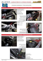
Fig. 1<br />
4
Solo per le forcelle 46 9552 e 46 9627: smontare il parafango dalla forcella originale.<br />
3) Togliere i due coperchi del manubrio ponendo molta attenzione a non<br />
danneggiarli (vedi Fig. 2)<br />
4) Svitando la vite che lo fissa al tubo di sterzo (part. 5, Fig. 1) togliere il manubrio<br />
dalla forcella e rovesciarlo in avanti avendo cura di non danneggiare i vari cavi<br />
ad esso collegati.<br />
5) Svitando la ghiera e l’anello cuscinetto superiore (part. 1-3, Fig. 1) si può<br />
ora smontare la forcella ORIGINALE dal vostro scooter, avendo cura di non<br />
danneggiare le due ralle a sfere (part. 4-6, Fig. 1). Togliere il cavo del contachilometri<br />
dalla sua sede di ancoraggio sul parafanghi ed il tubo del freno anteriore.<br />
Only for 46 9552 and 46 9627 forks: disassemble the original fork’s fender.<br />
3) Remove the two plastic covers on handlebar, paying attention not to damage<br />
them (see Fig. 2).<br />
4) Unscrew the screw that fastens the handlebar to the steering tube (part. 5,<br />
Fig. 1) and then remove the handlebar from the fork and turn it upside down,<br />
paying attention to avoid damage to the cables connected.<br />
5) After unscrewing the lock nut and the upper bearing ring (part. 1-3, Fig. 1),<br />
you can now remove your scooter’s ORIGINAL fork, paying attention not<br />
to damage the two ball-bearing fifth wheels (part. 4-6, Fig. 1). Remove the<br />
odometer cable from its anchor point on the fenders and the front brake tube.<br />
Nur bei den Gabeln 46 9552 und 46 9627: demontieren sie den originalen Kotflügel<br />
3) Entfernen die die beiden Kunststoffabdeckungen am Lenker, achten sie dabei<br />
darauf diese nicht zu beschädigen (vgl. Fig. 2).<br />
4) Lösen sie die Schraube mit der der Lenker am Schaftrohr befestigt ist (Teil 5,<br />
Fig. 1), ziehen sie dann den Lenker vom Schaft und drehen sie ihn auf den<br />
Kopf; achten sie dabei darauf keine Kabel und Züge zu beschädigen.<br />
5) Lösen sie die Kontermutter des Steuersatzes und entfernen sie den oberen Lagerring<br />
(Teil 1-3, Fig. 1). Sie können nun die Originalgabel entfernen. Achten sie dabei<br />
darauf dass sie die Lagerringe des Steuersatzes nicht beschädigen (Teil 4-6, Fig.<br />
1). Lösen sie die Tachowelle und die Bremsleitun aus ihren Führungen am Kotflügel. Fig. 2<br />
5
ITALIANO<br />
6) Una volta sfilata la forcella originale si può procedere allo smontaggio dell’eventuale parafango superiore (part. 20, Fig. 3).<br />
7) Smontare dalla forcella originale l’anello cuscinetto inferiore ed il parapolvere avendo cura di non danneggiarli (part. 7-8,<br />
Fig. 1).<br />
8) Smontare dalla ruota originale il disco freno.<br />
ENGLISH<br />
6) After removing the original fork, disassemble the upper fender (part. 20, Fig. 3) if present.<br />
7) Remove the lower bearing ring and the dust cover from the original fork, paying attention to avoid damage (part. 7-8, Fig. 1).<br />
8) Remove the brake disc from the original wheel.<br />
DEUTSCH<br />
6) Nachdem die originale Gabel ausgebaut ist demontieren sie den oberen Kotflügel (sofern vorhanden) (Teil 20, Fig. 3).<br />
7) Nehmen sie den unteren Lagerring und den Staubschutz von der originalen Gabel, achten sie dabei darauf diese nicht<br />
zu zerstören. (Teil 7-8, Fig. 1).<br />
8) Bauen sie die Bremsscheibe vom Originalrad ab.<br />
6
MONTAGGIO FORCELLA<br />
1.1) Per le forcelle 46 9550 e 46 9552:<br />
Svasare la sede delle viti di fissaggio sul disco freno in modo che le viti date in corredo (part. 28, Fig. 3 e Fig. 4) non<br />
sporgano dal piano del disco per più di 2 mm. Fissare ora il disco freno così modificato alla ruota originale serrando a<br />
fondo le tre viti utilizzando un blocca filetti tipo Loctite 242. Prestare attenzione al senso di rotazione del disco inciso sul<br />
disco stesso.<br />
Qualora il disco originale presenti irregolarità di rotazione (superiore a 0,1 mm) o eccessiva usura, sostituirlo con un disco<br />
freno Malossi Brake Power Disc.<br />
NB: Se si deve montare la forcella 46 9550, praticare due fori di diametro 16 mm sul parafango originale (part. 20, Fig. 3)<br />
come indicato in Fig. 3.<br />
<strong>FORK</strong> ASSEMBLY<br />
1.1) For forks 46 9550 and 46 9552:<br />
Countersink the housing of the fixing screws on the brake disc so that the screws supplied (part. 28, Fig. 3 and Fig. 4) do<br />
not protrude from the surface of the disc by more than 2 mm. Now attach the brake disc modified in this way to the original<br />
wheel by firmly tightening the three screws using Loctite 242-type thread glue. Respect the disc rotation direction cut into<br />
the disc itself. If the original disc shows signs of irregular rotation (of more than 0.1 mm) or excessive wear, replace it with<br />
a Malossi Brake Power Disc brake disc.<br />
NOTE: When assembling the 46 9550 fork, drill two 16 mm diameter holes on the original fender (part. 20, Fig. 3) as shown<br />
in Fig. 3.<br />
<strong>GABEL</strong> ZUSAMMENBAU<br />
1.1) Für Gabeln mit den Teilenummer 46 9550 und 46 9552:<br />
Senken sie die Sitze der Befestigungsschrauben an der Bremsscheibe so an dass die mitgelieferten Schrauben nicht mehr<br />
als 2 mm über die Bremsscheibe überstehen. (Teil 28, Fig. 3 und Fig. 4). Bauen sie nun die so bearbeitete Bremsscheibe<br />
an das originale Rad an. Kleben sie die Schrauben mit Locite 242 Schraubensicherungskleber ein. Achten sie bei der<br />
Montage auf die Drehrichtung der Bremsscheibe. Sollte die originale Bremsscheibe unrund laufen (mehr als 0.1 mm) oder<br />
verschlissen sein montieren sie als Ersatz eine Malossi Brake Power Disc Bremsscheibe.<br />
ACHTUNG: Beim Einbau der 46 9550 Gabel bohren sie bitte 2 Löcher mit 16 mm Durchmesser in den originalen Kotflügel<br />
(Teil. 20, Fig. 3) wie auf Fig. 3 ersichtlich.<br />
7
ITALIANO<br />
ENGLISH<br />
DEUTSCH<br />
1.2) Per le forcelle 46 9627 e 4613086:<br />
Dopo aver pulito accuratamente la sede di montaggio del disco freno sulla ruota originale inserire il nuovo disco freno<br />
prestando attenzione al senso di rotazione inciso sul disco. Fissare il disco freno con le 5 viti fornite nel kit chiudendole<br />
a croce ed utilizzando un buon blocca filetti tipo Loctite 242. Chiudere le 5 viti con una coppia di 12 Nm.<br />
2) Montare il parapolvere (part. 8, Fig. 1) sulla nuova forcella Malossi.<br />
3) Montare l’anello cuscinetto inferiore (part.7, Fig. 1) sulla forcella Malossi avendo l’accortezza di portarlo ad una<br />
temperatura non superiore ai 150 °C al fine di facilitare l’inserimento nella propria sede, avendo cura di non danneggiare<br />
in nessun modo la sede di scorrimento delle sfere.<br />
4) Montare sulla forcella Malossi i due bulloncini (part. 18, Fig. 1) con i rispettivi controdadi (part. 19, Fig. 1) che servono<br />
per regolare le battute di fine corsa dello sterzo.<br />
1.2) For 46 9627 - 4613086 forks:<br />
After thoroughly cleaning the assembly seat for the brake disc on the original wheel, insert the new brake disc while<br />
respecting the rotation direction cut into the disc. Fasten the brake disc in place using the 5 screws supplied in the kit by<br />
cross procedure and then using a good thread glue such as Loctite 242. Tighten these 5 screws to a torque of 12 Nm.<br />
2) Assemble the dust cover (part. 8, Fig. 1) on the new Malossi fork.<br />
3) Assemble the lower bearing ring (part. 7, Fig. 1) on the Malossi fork, while taking the measure of heating it to a<br />
temperature of no more than 150°C in order to facilitate insertion in the housing and paying attention not to damage<br />
the ball bearing housing.<br />
4) Assemble the two bolts (part. 18, Fig. 1) with their lock nuts (part. 19, Fig. 1) that serve for the adjustment of the<br />
steering stroke end points on the Malossi fork.<br />
1.2) Für 46 9627 und 4613086 Gabeln:<br />
Reinigen sie den Sitz der Bremsscheibe auf dem originalen Rad gründlich, montieren sie dann die neue Bremsscheibe<br />
unter Beachtung der Laufrichtung. Ziehen sie die 5 mitgelieferten Schrauben über Kreuz bis zu einem Anzugsmoment<br />
von 12 Nm an., Benutzen sie dabei einen Schraubensicherungskleber (Loctite 242).<br />
2) Montieren sie den Staubschutz (Teil 8, Fig. 1) auf der neuen Malossi Gabel.<br />
3) Montieren sie den unteren Steuersatzlagerring (Teil 7, Fig. 1) auf der Malossi Gabel, erhitzen sie den Ring auf maximal<br />
150° C und achten sie darauf bei der Montage die Lagerfläche nicht zu beschädigen.<br />
4) Montieren sie die beiden Schrauben (Teil 18, Fig. 1) mit den dazu gehörenden Anschlagschrauben (Teil 19, Fig. 1) mit<br />
denen der Lenkanschlag der Malossi Gabel eingestellt wird.<br />
8
5.1) Per la forcella 46 9550:<br />
Montare sul parafango originale (part. 20, Fig. 3), servendosi dei due bulloncini (part. 21, Fig. 3) le due staffe (part. 22,<br />
Fig. 3) che servono per fissare il parafango alla forcella. Prima di serrare il parafango sulla forcella tramite i due bulloncini<br />
M5 (part. 24, Fig. 3) bisogna avere cura di centrare il parafango al centro della forcella, dopo di che si possono stringere i<br />
bulloni (part. 24, Fig. 3 e part. 21, Fig. 3).<br />
5.2) Per le forcelle 46 9552, 46 9627 e 4613086:<br />
Inserire nello stelo destro le due fascette gommate in dotazione (part. 32, Fig. 4 e Fig. 5) ed inserire la terza fascetta nello<br />
stelo sinistro. Con i tre bulloncini (part. 30, Fig. 3 e Fig. 4) con testa bombata ed i dadi autobloccanti (part. 31, Fig. 4 e Fig.<br />
5) fissare il parafango (part. 29, Fig. 4 e Fig. 5) agli steli della forcella, avendo cura di lasciare 10-15 mm fra la ruota ed il<br />
parafango e centrando il parafango rispetto alla forcella.<br />
5.1) For 46 9550 fork:<br />
Using two bolts (part. 21, Fig. 3), assemble the two brackets (part. 22, Fig. 3) on the original fender (part. 20, Fig. 3) that<br />
fasten the fender to the fork. Before bolting the fender on the fork using the two M5 bolts (part. 24, Fig. 3), carefully center<br />
the fender on the fork, after which the bolts (part. 24, Fig. 3 and part. 21, Fig. 3) can be tightened.<br />
5.2) For 46 9552, 46 9627 and 4613086 forks:<br />
Insert the two hose clamps supplied (part. 32, Fig. 4 and Fig. 5) into the right fork rod and insert the third clamp into the<br />
left fork rod. Using the three crown head bolts (part. 30, Fig. 4 and Fig. 5) and the self-locking nuts (part. 31, Fig. 4 and<br />
Fig. 5) fasten the fender (part. 29, Fig. 4 and Fig. 5) to the fork’s rods, making sure to leave a gap of 10-15 mm between<br />
the wheel and the fender and making sure to center the fender over the fork.<br />
5.1) Für 46 9550 Gabel:<br />
Montieren sie die beiden Halterungen mit denen der Kotflügel an der Gabel befestigt wird mit zwei Schrauben (Teil 21,<br />
Fig. 3, Teil 22, Fig. 3) auf dem original Kotflügel (Teil 20, Fig. 3). Bevor sie den Kotflügel an der Gabel mit den beiden<br />
M5 Schrauben (Teil 24, Fig. 3) festschrauben richten sie den Kotflügel sorgfältig auf der Gabel aus. Danach können die<br />
Schrauben (Teil 24, Fig. 3 und Teil 21, Fig. 3) angezogen werden.<br />
5.2) Für 46 9552, 46 9627 und 4613086 Gabeln:<br />
Befestigen sie die zwei der mitgelieferten Führungen (Teil 32, Fig. 4 und Fig. 5) am rechten Holm der Gabel, den dritten am<br />
linken Gabelholm. Benutzen sie dazu die drei Kronenkopfschrauben (Teil 30, Fig. 4 und Fig. 5) und die selbstsichernden<br />
Muttern (Teil 31, Fig. 4 und Fig. 5). Ziehen sie den Kotflügel an den Gabelholmen fest (Teil 29, Fig. 4 und Fig. 5), achten sie<br />
dabei darauf dass zwischen Reifen und Kotflügel 10-15mm Luft sein müssen, und dass der Kotflügel mittig über dem Rad<br />
stehen sollte.<br />
9
ITALIANO<br />
6) Inserire la ralla inferiore (part. 6, Fig. 1) nel tubo di sterzo e posizionarla sull’anello cuscinetto inferiore, avendo cura se<br />
necessario di lubrificarla con una adeguata quantità di grasso (Fiat Z2 oppure IP Autogrease LZ).<br />
7) Inserire la vostra nuova forcella Malossi nel canotto di sterzo dello scooter avendo cura che le due viti di fermo sterzo (part. 18,<br />
Fig. 1) siano rivolte verso la parte posteriore dello scooter.<br />
8) Inserire nella parte superiore del tubo di sterzo la ralla superiore (part. 4, Fig. 1) dopo averla adeguatamente lubrificata<br />
con grasso. Fissare provvisoriamente la forcella avvitando l’anello cuscinetto superiore (part. 3, Fig. 1).<br />
9) Inserire nei propri alloggiamenti sul parafango superiore il cavo del contachilometri e il tubo della pinza freno.<br />
10) È fondamentale serrare correttamente l’anello cuscinetto superiore e la ghiera al fine di avere uno sterzo fluido ma<br />
senza eccessivo gioco. Per fare questo, utilizzare attrezzo Piaggio 19.1.20055.<br />
ENGLISH<br />
6) Insert the lower fifth wheel (part. 6, Fig. 1) in the steering tube and position it on the lower bearing ring, making sure<br />
to adequately grease (using Fiat Z2 or IP Autogrease LZ types) if required.<br />
7) Insert your new Malossi fork in your scooter’s steering tube, making sure that the two steering retainer screws (part.<br />
18, Fig. 1) face the scooter’s rear.<br />
8) Insert the upper fifth wheel (part. 4, Fig. 1) in the upper part of the steering tube after adequate greasing. Temporarily<br />
fasten the fork in place by screwing in the upper bearing ring (part. 3, Fig. 1).<br />
9) Insert the odometer cable and the brake caliper tube into their respective housings on the upper fender.<br />
10) It is very important for the upper bearing ring and the respective lock nut to be tightened correctly in order to ensure<br />
fluid steering without excessive play. For correct tightening, use Piaggio Tool 19.1.20055.<br />
DEUTSCH<br />
10<br />
6) Setzen sie den unteren Lagerring (Teil 6, Fig. 1) auf den Gabelschaft auf und legen sie ihn auf den unteren Lagerring,<br />
stellen sie sicher das dieser ausreichend geschmiert ist (benutzen sie dazu Fiat 2 oder IP Autogrease LZ oder ein<br />
vergleichbares Fett).<br />
7) Setzen sie ihre neue Malossi Gabel in das Steuerrohr ihres Rollers ein, stellen sie dabei sicher dass die beiden<br />
Halteschrauben (Teil 18, Fig. 1) zum Heck des Rollers zeigen.<br />
8) Setzen sie den oberen Lagerring (Teil 4, Fig. 1) in die obere Lagerschale ein, fetten sie ihn großzügig. Halten sie die<br />
Gabel in dieser Position in dem sie den oberen Konusring aufschrauben (Teil 3, Fig. 1).<br />
9) Setzen sie die Tachowelle und die Bremsleitung in ihre jeweiligen Führungen im Kotflügel ein.<br />
10) Es ist sehr wichtig mit dem oberen Lagerring und die Kontermutter das Lagerspiel so einzustellen dass die Gabel sich<br />
leicht, aber spielfrei dreht. Benutzen sie dazu das Piaggio Werkzeug 19.1.20055.
10.1) Chiudere l’anello superiore (part. 3, Fig. 1) con una coppia torcente di 50-60 Nm e poi svitare l’anello di 80-90°.<br />
10.2) Inserire la rondella di fermo (part. 2, Fig. 1).<br />
10.3) Chiudere la ghiera (part. 1,Fig. 1) con una coppia torcente di 30-40 Nm.<br />
11) Per le forcelle 46 9550, 46 9552, 46 9627 e 4613086:<br />
Rimontare il manubrio serrando il bullone con una coppia torcente di 45-50 Nm, allineandolo grazie al riferimento presente<br />
sulla parte superiore del tubo di sterzo.<br />
Dopo i primi 500 Km verificare la chiusura dell’anello e della ghiera.<br />
12) Rimontare i coperchi del manubrio come in origine.<br />
13) Rimontare la ruota originale con il disco freno modificato avendo cura di inserire anche il rinvio del contachilometri.<br />
10.1) Tighten the upper ring (part. 3, Fig. 1) to a torque of 50-60 Nm and then unscrew the ring by 80-90°.<br />
10.2) Insert the lock washer (part. 2, Fig. 1).<br />
10.3) Tighten the lock nut (part. 1, Fig. 1) to a torque of 30-40 Nm.<br />
11) For 46 9550, 46 9552, 46 9627 and 4613086 forks:<br />
Re-assemble the handlebar by tightening the bolt to a torque of 45-50 Nm, aligning it using the reference mark present on<br />
the upper part of the steering tube.<br />
Check ring and lock nut tightening after 500 km.<br />
12) Reassemble the handlebar plastic covers as before.<br />
13) Reassemble the original wheel with the modified brake disc, making sure to also insert the odometer transmission.<br />
10.1) Ziehen sie den Konusring (Teil 3, Fig. 1) mit einem Anzugsmoment von 50-60 Nm an, drehen sie dann den Ring um 80-90°.<br />
10.2) Legen sie die Nasenscheibe ein (Teil 2,Fig. 1).<br />
10.3) Ziehen sie die Kontermutter (Teil 1, Fig. 1) mit einem Anzugsmoment von 30-40 Nm an.<br />
11) Für 46 9550, 46 9552, 46 9627 und 4613086 Gabeln:<br />
Montieren sie den Lenker und ziehen sie die Schraube mit einem Moment von 45-50 Nm an, achten sie dabei darauf<br />
dass er dabei fluchtend auf die Referenzmarkierung auf dem Gabelschaft ausgerichtet ist. Prüfen sie nach 500km das<br />
Lenkkopflagerspiel, stellen sie gegebenenfalls neu ein, kontrollieren sie den Konterring und ziehen sie ihn gegebenenfalls nach.<br />
12) Montieren sie die Lenkerverkleidung.<br />
13) Montieren sie das originale Rad mit der modifizierten Bremsscheibe, achten sie dabei darauf den Tachoantrieb richtig einzusetzen.<br />
11
ITALIANO<br />
14.1) Inserire il perno ruota come da Fig. 1 accertandovi che la vite (part. 12, Fig. 1) sia lenta.<br />
14.2) Per la forcella 4613086:<br />
Per centrare la ruota sulla forcella utilizzare i due distanziali ( L= 7.5 mm) presenti nel kit.<br />
15) Con una chiave a brugola da 8 mm serrare a fondo il perno ruota con una coppia torcente 40-50 Nm e dopo aver fatto<br />
affondare completamente la vostra nuova forcella Malossi una decina di volte, serrare il dado di fermo (part. 12, Fig.<br />
1) che blocca il perno ruota allo stelo sinistro.<br />
16) Per le forcelle 46 9550, 46 9552, 46 9627 e 4613086:<br />
Regolare le due viti (part. 18, Fig. 1) per i fine corsa dello sterzo e serrare il tutto con i due dadi (part. 19, Fig. 1).<br />
ENGLISH<br />
14.1) Insert the wheel pin as shown in Fig. 1, making sure that the screw (part. 12, Fig. 1) is partially unscrewed.<br />
14.2) For 4613086 fork:<br />
To center the wheel on the fork, use the two spacers (mm 7.5) inserted into the kit.<br />
15) Using an 8 mm setscrew wrench, firmly tighten the wheel pin to a torque of 40-50 Nm. After sinking your new Malossi<br />
fork completely down and up a dozen times or so, tighten the lock nut (part. 12, Fig. 1) that locks the wheel pin to the<br />
left fork rod.<br />
16) For 46 9550, 46 9552, 46 9627 and 4613086 forks:<br />
Adjust the two screws (part. 18, Fig. 1) for the steering stroke ends and lock everything with the two nuts (part. 19, Fig. 1).<br />
DEUTSCH<br />
14.1) Setzen sie den Radbolzen gemäß Fig. 1 ein, achten sie dabei darauf dass die Schraube (Teil 12, Fig. 1) gelöst ist.<br />
14.2) Für 4613086 Gabel:<br />
Zentrieren sie das Rad in der Gabel mit Hilfe der beiden im Kit enthaltenen Spacer (mm 7.5).<br />
15) Ziehen sie den Radbolzen mit einem 8mm Inbusschlüssel mit einem Drehmoment von 40-50 Nm an. Tauchen sie ihre<br />
neue Malossi Gabel mit gezogener Bremse 10-12 ein, ziehen sie dann die die Klemmschraube (Teil 12, Fig. 1) die den<br />
Radbolzen im linken Gabelholm klemmt an.<br />
16) Für 46 9550, 46 9552, 46 9627 und 4613086 Gabeln:<br />
Justieren sie die beiden Schrauben (Teil 18, Fig. 1) des Lenkanschlags und sichern sie beides mit den beiden Muttern.<br />
(Teil 19, Fig. 1).<br />
12
MONTAGGIO PINZA FRENO<br />
1.1) Per la forcella 46 9550, con la sola esclusione dei veicoli Piaggio Nrg Mc3 (per i quali è necessario attenersi alle<br />
indicazioni riportate nel punto 1.2 a seguire):<br />
Montare la nuova pinza freno avendo cura di controllare che il disco freno sia centrato nella sede della pinza freno;<br />
eventualmente spessorare con rasamenti opportuni fino ad ottenere un adeguato centraggio del disco freno nella pinza<br />
freno.<br />
Scollegare dalla pinza originale il tubo del liquido frenante e collegarlo alla vostra nuova pinza freno.<br />
1.2) Per la forcella 46 9552 e per i veicoli Piaggio NRG Mc3:<br />
Per questi veicoli non é necessario sostituire la pinza freno originale.<br />
Inserire fra l’attacco superiore della pinza freno e la pinza originale il distanziale (part. 34, Fig. 4) e serrare il tutto con i due<br />
BRAKE CALIPER ASSEMBLY<br />
1.1) For 46 9550 fork, with the exception of Piaggio Nrg Mc3 vehicles (for which the instructions provided from point 1.2<br />
onwards must be followed):<br />
Assemble the new brake caliper making sure to check that the brake disc is centred over the brake caliper housing; if<br />
necessary, create the right distance using adequate shims until the adequate centring of the brake disc in the brake caliper<br />
is obtained.<br />
Disconnect the brake fluid hose from the original caliper and connect it to your new brake caliper.<br />
1.2) For 46 9552 forks and Piaggio NRG Mc3 vehicles:<br />
These vehicles do not require the replacement of the original brake caliper.<br />
Insert the spacer (part. 34, Fig. 4) between the brake caliper’s upper attachment and the original caliper and then tighten<br />
BREMSZANGENEINBAU<br />
1.1) Für 46 9550 Gabel, mit Ausnahme Piaggio Nrg Mc3 (für diese lesen sie die Einbauanleitung ab Punkt 1.2):<br />
Montieren sei die Bremszange mittig über der Bremsscheibe; falls notwendig distanzieren sie die Bremsscheibe mit Shims<br />
bis sie zentriert in der Zange sitzt.<br />
Lösen sie die Bremsleitung von der Originalzange and schrauben sie sie an die neue Bremszange.<br />
1.2) Für 46 9552 Gabeln und Piaggio NRG Mc3:<br />
Bei diesen Fahrzeugen kann die originale Zange weiter benutzt werden.<br />
Bauen sie den Bremsadapter (Teil 34, Fig. 4) zwischen den Gabelbefestigungspunkten und der Bremszange ein, ziehen sie<br />
die beiden Schrauben (Teil 27, Fig. 4) und die ORIGINALE Schraube an (Teil 35, Fig. 4).<br />
Setzen sie die mitgelieferten 2 mm dicken Beilagscheiben 8x18 zwischen der Zange und dem unteren Befestigungspunkt ein.<br />
13
ITALIANO<br />
ENGLISH<br />
bulloni (part. 27, Fig. 4) ed il bullone ORIGINALE (part. 35, Fig. 4).<br />
Tra la pinza e l’attacco inferiore inserire la rondella piana 8x18 spessore 2 mm data in dotazione.<br />
Prima di serrare il tutto, accertarsi che il disco freno sia centrato nella sede della pinza freno; eventualmente spessorare<br />
con rasamenti opportuni fino ad ottenere un adeguato centraggio del disco freno nella pinza freno.<br />
1.3) Per le forcelle 46 9627 e 4613086:<br />
Montare sulla pinza originale il distanziale fornito nel kit e fissarlo alla pinza tramite le due viti che si inseriscono<br />
nelle sedi per la testa. Fissare la pinza con il distanziale alla forcella, utilizzando le due viti M8 originali, avendo cura<br />
di controllare che il disco freno sia centrato nella sede della pinza freno; eventualmente spessorare fra distanziale e<br />
fissaggio sul gambale della forcella con opportuni rasamenti fino ad ottenere un adeguato centraggio del disco freno<br />
nella pinza freno.<br />
the entire assembly using the two bolts (part. 27, Fig. 4) and the ORIGINAL bolt (part. 35, Fig. 4).<br />
Insert the 2 mm thick plain washer 8x18 supplied between the caliper and the lower attachment.<br />
Before definitively tightening everything, make sure that the brake disc is centred in the brake caliper housing; if<br />
necessary, create the right distance using adequate shims until the adequate centring of the brake disc in the brake<br />
caliper is obtained.<br />
1.3) For 46 9627 and 4613086 forks:<br />
Assemble the spacer supplied in the kit on the original caliper and fasten it in place using the two screws to be inserted in the<br />
housings for the head. Fasten the caliper with the spacer to the fork using the two original M8 screws, making sure that the<br />
brake disc is centred in the brake caliper housing; if necessary, create the right distance between the spacer and the fastening<br />
point on the fork’s stem using adequate shims until the adequate centring of the brake disc in the brake caliper is obtained.<br />
DEUTSCH<br />
Stellen sie, bevor sie alle Schrauben endgültig anziehen, sicher dass die Bremsscheibe mittig im Bremszangengehäuse<br />
steht, falls dem nicht so sein sollte zentrieren sie die Bremsscheibe mit den entsprechenden Shims bis sie zentriert in<br />
der Zange steht.<br />
1.3) Für 46 9627 und 4613086 Gabeln:<br />
Montieren sie die im Lieferumfang enthaltenen Spacer an der originalen Bremszange, ziehen sie die beiden Schrauben<br />
an. Schrauben sie nun die Bremszange mit den beiden originalen M8 Schrauben und den Spacern an der Gabel fest,<br />
achten sie dabei darauf dass die Bremsscheibe mittig im Bremszangengehäuse sitzt. Sollte dies nicht der Fall sein<br />
benutzen sie Shims um die Bremsscheibe zwischen der Zange zu zentrieren.<br />
14
ATTENZIONE: Le superfici verniciate vengono danneggiate dal contatto con il liquido frenante.<br />
La presenza di liquido frenante sulle pastiglie freno e sul disco freno riduce enormemente l’efficienza<br />
dell’impianto frenante.<br />
Nel caso in cui ciò si verifichi, pulire con un buon solvente le superfici che sono venute a contatto con il liquido<br />
frenante.<br />
IMPORTANT: Painted surfaces are damaged by contact with brake fluid.<br />
The presence of brake fluid on the brake pads and brake disc reduces braking system efficiency<br />
considerably.<br />
Whenever brake fluid has spread to these place, clean all contaminated surfaces using a good solvent.<br />
ACHTUNG: Bremsflüssigkeit kann Lackoberflächen angreifen. Bremsflüssigkeit auf der Bremsscheibe oder<br />
den Bremsbelägen reduziert die Bremsleistung erheblich. Sollte Bremsflüssigkeit auf Scheibe oder Beläge<br />
gelangt sein reinigen sie alle betroffenen Flächen mit Bremsenreiniger.<br />
15
ITALIANO<br />
ENGLISH<br />
SPURGO DELL’IMPIANTO FRENANTE<br />
NB: Questa operazione deve essere effettuata in tutti i veicoli che richiedono la sostituzione della pinza originale.<br />
Il veicolo deve essere posizionato sul cavalletto su una superficie piana.<br />
Una volta collegata la nuova pinza freno al tubo del liquido dei freni, bisogna eliminare ogni presenza di bolle d’aria dal<br />
circuito dell’impianto frenante. Per fare questo procedere come indicato di seguito:<br />
1) Con la valvola di sfiato sulla pinza freno chiusa, riempire fino al massimo livello il serbatoio del liquido dei freni con liquido per freni<br />
DOT 4.<br />
2) Con la leva del freno azionare il pistoncino fin tanto che non si notano più fuoriuscite di bolle d’aria dal forellino del<br />
serbatoio.<br />
3) Collegare un tubicino, possibilmente trasparente, alla vite di spurgo presente sulla pinza freno ed immergerlo in un<br />
BRAKING SYSTEM AIR BLEEDING<br />
NOTE: This operation must be performed for all vehicles that require the replacement of the original caliper.<br />
The vehicle must be positioned on a stand on a flat surface.<br />
After connecting the new brake caliper to the brake fluid hose, all air bubbles must be eliminated from the braking system<br />
by proceeding as follows:<br />
1) With the bleeder valve on the brake caliper closed, fill the brake fluid tank with DOT 4 brake fluid.<br />
2) Using the brake lever, work the piston until no more air bubbles are seen to emerge from the hole in the tank.<br />
3) Connect a hose (preferably transparent) to the air bleeding screw on the brake caliper and insert the other end into a<br />
recipient containing brake fluid.<br />
DEUTSCH<br />
ENTLÜFTEN DES BREMSSYSTEMS<br />
BITTE BEACHTEN: Führen sie diesen Arbeitsgang mit dem Fahrzeug auf dem Hauptständer auf ebenem Untergrund<br />
durch. Betrifft nur Fahrzeuge bei denen die originale Bremszange durch eine neue ersetzt wird.<br />
Fahrzeug auf ebener Fläche auf den Hauptständer stellen.<br />
Nach dem die neue Bremszange angeschlossen ist muss die Bremsleitung entlüftet werden. Gehen sie dabei wie folgt vor:<br />
1) Entlüftungsschraube an der Bremszange schließen, Ausgleichsbehälter mit DOT 4 Bremsflüssigkeit füllen.<br />
2) Pumpen sie mit dem Bremshebel so lange bis keine Blasen mehr aus dem Entlüftungsloch des Ausgleichbehälters mehr<br />
aufsteigen.<br />
3) Stecken sie einen Schlauch (vorzugsweise transparent) auf die Entlüftungsschraube auf, hängen sie dessen anderes<br />
Ende in mit Bremsflüssigkeit gefülltes Behältnis.<br />
16
ecipiente contenente il liquido per i freni.<br />
4) Tirare la leva del freno e contemporaneamente allentare la vite di spurgo e far defluire le bolle d’aria presenti nella pinza freno.<br />
5) Chiudere la vite di spurgo e poi rilasciare la leva del freno e ripristinare il livello nel serbatoio del liquido dei freni.<br />
6) Ripetere l’operazione fino a che dalla vite di spurgo non escono più bollicine d’aria.<br />
NB:<br />
Se durante le operazioni di spurgo l’aria continua ad uscire, controllare tutti i raccordi e le tenute<br />
del circuito dell’impianto frenante.<br />
ATTENZIONE: Si consiglia vivamente di controllare l’impianto frenante anteriore per i primi chilometri provando<br />
la frenata a partire da velocità molto basse in quanto se lo spurgo aria non viene eseguito<br />
correttamente ed in modo scrupoloso, si corre il rischio che l’impianto frenante non funzioni.<br />
4) Squeeze the brake lever while simultaneously loosening the bleeding screw to bleed away all the air bubbles contained in the<br />
brake caliper.<br />
5) Close the bleeding screw and then release the brake lever and top up the level of brake fluid in the tank.<br />
6) Repeat the operation until no more air bubbles emerge from the bleeding screw.<br />
NOTE:<br />
If air continues emerging during these air bleeding operations, check all the connectors and the<br />
sealing in the entire brake system circuit.<br />
IMPORTANT: We strongly recommend checking the front wheel’s braking system during the first kilometres of<br />
use by checking braking efficiency starting with low speed stopping because if air bleeding has not<br />
been performed correctly or thoroughly, the risk of inefficient braking arises.<br />
4) Ziehen sie den Bremshebel während sie (oder ein Helfer) gleichzeitig die Entlüftungsschraube öffnen.<br />
5) Schließen sie die Entlüftungsschraube, lösen sie dann den Bremshebel. Füllen sie gegebenenfalls Bremsflüssigkeit im<br />
Ausgleichsbehälter nach.<br />
6) Wiederholen sie den Vorgang bis keine Luftblasen mehr aus der Entlüftungsschraube austreten.<br />
BITTE BEACHTEN: Wenn sich die Bremse nicht entlüften lässt überprüfen sie alle Schraubverbindungen und<br />
Dichtungen in der Bremsleitung.<br />
ACHTUNG: Wir empfehlen dringend auf den ersten Fahrtkilometern die Bremse mit Testbremsungen aus<br />
langsamer Fahrt zu überprüfen. Wenn die Bremsanlage nicht vollständig entlüftet ist steigt das<br />
Risiko dass die Bremsleistung nachlässt.<br />
17
ITALIANO<br />
F36R - Forcella Racing - Forcella da competizione ai massimi livelli<br />
Questa forcella é stata studiata e progettata utilizzando la migliore tecnologia attualmente disponibile nel settore<br />
competizione cross a livello internazionale.<br />
La forcella anteriore F36R viene realizzata completamente dal pieno per ottenere le forme e la rigidità strutturale atte a<br />
sopportare i carichi elevatissimi ai quali sono sottoposti i mezzi durante le competizioni.<br />
La forcella F36R è una forcella al top della tecnologia delle sospensioni.<br />
ENGLISH<br />
F36R – Racing Fork - Racing fork with the highest performance<br />
This fork was studied and designed using the best technology currently available in the cross racing sector at the<br />
international level.<br />
The F36R front fork is machined entirely from the solid in order to obtain the shape and structural strength required to<br />
withstand the elevated loads applied during competition.<br />
The F36R fork represents the crown of suspension technology.<br />
DEUTSCH<br />
F36R – Racing Gabel – High Performance Racing Gabel<br />
Die F36R wurde mit der aufwändigsten heute erhältlichen im internationalen Rennsport verfügbaren Technologie entwickelt,<br />
alle Gabelbauteile werden aus dem Vollen gefräst. Nur so können die für die strukturelle Stabilität notwendigen Formen<br />
die<br />
für die hohen Belastungen im Rennbetrieb notwendig sind umgesetzt werden.<br />
Die F36R Gabel repräsentiert den Höhepunkt der Fahrwerkstechnik.<br />
18
Caratteristiche tecniche:<br />
1) Tubo di sterzo in acciaio speciale ad alta resistenza, lavorato su macchine a CN.<br />
2) Trapezio in acciaio legato forgiato, lavorato con macchine a CN.<br />
3) Tubi di scorrimento di Ø 36 mm in acciaio speciale rettificati, lappati con riporto di titanio per assicurare una scorrevolezza<br />
eccezionale.<br />
4) Gambali in lega speciale di alluminio (Anticorodal) estruso, lavorati dal pieno con macchine a CN ed anodizzati.<br />
5) Attacchi ruota in lega speciale di alluminio ricavati dal pieno per asportazione di trucciolo.<br />
6) Sistema idraulico mono cartuccia con scorrimento su boccole D.U. e boccola paraolio oscillante per limitare a valori<br />
bassissimi gli attriti di scorrimento.<br />
7) Regolazione fine del precarico molla.<br />
8) Regolazione della frenatura in estensione.<br />
Technical features:<br />
1) Head tubes in special high-resistance steel produced on NC machines.<br />
2) Crossbar in special forged alloy steel produced on Nc machines.<br />
3) 36 mm Ø telescopic tubes in special steel, ground and lapped with titanium coating for exceptional smoothness of<br />
movement.<br />
4) Stem in special extruded aluminium alloy (Anticorodal), machined from the solid using NC machines and anodized.<br />
5) Wheel couplings in special aluminium alloy machined from the solid by chip machining.<br />
6) Single-cartridge hydraulic piston system with sliding on D.U. bushes and oscillating oil-seal bush to keep friction to an<br />
absolute minimum.<br />
7) Spring loading adjustment.<br />
8) Rebound braking adjustment.<br />
Technische Daten:<br />
1) Schaftrohr CNC gefertigt aus hochfestem Spezialstahl.<br />
2) Gabelkrone CNC gefräst aus geschmiedetem Spezialaluminium.<br />
3) 36 mm Ø Teleskoprohr aus geschliffenem und poliertem Spezialstahl, Titanbeschichtet für möglichst niedriges<br />
Losbrechmoment.<br />
4) Tauchrohre aus anodisiertem antikorrosivem Aluminiumextrusionsguss, CNC bearbeitet.<br />
5) Radklemmfäuste aus Spezialalluminium, CNC gefräst.<br />
6) Einkartuschen Dämpfung mit auf D.U. Buchsen laufendem Kolben, oszilierender Öldichtung um die Innenreibung auf ein<br />
Mindestmass zu reduzieren.<br />
7) Federvorspannung einstellbar.<br />
8) Zugstufe einstellbar.<br />
19
ITALIANO<br />
9) Regolazione della frenatura in compressione.<br />
10) Escursione della forcella: art. 4613062 e 4613090: 90 mm.<br />
La forcella F36R viene fornita di:<br />
- Disco freno maggiorato Ø 250 mm.<br />
- Viti, dadi e tutto quanto serve per il montaggio.<br />
ENGLISH<br />
9) Compression braking adjustment.<br />
10) Range of fork : 4613062 and 4613090: 90 mm.<br />
The F36R fork comes supplied with:<br />
- An oversized 250 mm Ø brake disc<br />
- Screws, nuts, and everything else required for assembly.<br />
DEUTSCH<br />
9) Druckstufe einstellbar.<br />
10 Gabelversionen: 4613062 und 4613090: 90 mm.<br />
Die F36R Gabel wird geliefert mit:<br />
- einer oversized 250 mm Ø Bremsscheibe<br />
- Schrauben, Muttern und allem zur Montage notwendigen Kleinteilen.<br />
20
Art. 4613090 - 4613062<br />
ISTRUZIONI DI MONTAGGIO<br />
Per il montaggio di questa nuova forcella da competizione si é ritenuto opportuno fornire un disco freno maggiorato.<br />
Si deve pertanto sostituire il disco freno originale (part. 33, Fig. 3) con il disco freno Malossi e fissarlo al mozzo della ruota con<br />
le viti svasate fornite in dotazione.<br />
Per la forcella 4613090: Per centrare correttamente la ruota sulla forcella , servirsi dei due distanziali presenti nel kit. Il distanziale<br />
più lungo (9 mm) deve essere montato sul lato disco freno.<br />
Per le restanti fasi di montaggio vedere l’istruzione riferita alla forcella F32S Art. 46 9627 (esclusi i punti 1 e 5 del paragrafo<br />
“MONTAGGIO FORCELLA”, pag. 7).<br />
ASSEMBLY INSTRUCTIONS<br />
We decided to provide an oversized brake disc for the assembly of this new racing fork.<br />
For the reason above, the original brake disc (part. 33, Fig. 3) must be replaced by the Malossi brake disc and fastened to the<br />
wheel hub using the three countersunk head screws supplied.<br />
For 4613090 fork: To center the wheel on the fork, use the two spacers inserted into the kit. Assemble the longer spacer (9<br />
mm) on brake disc side.<br />
For the remaining assembly phases, follow the instructions provided for the F32S fork Art. 46 9627 (with the exception of Points<br />
1 and 5 in the Paragraph entitled “<strong>FORK</strong> ASSEMBLY”, pg. 7).<br />
MONTAGEANLEITUNG<br />
Wir haben uns entschieden diese neue Renngabel mit einer oversized Bremsscheibe auszuliefern.<br />
Aus diesem Grund muss die originale Scheibe (Teil 33, Fig. 3) durch die Malossi Bremsscheibe ersetzt werden. Diese wird mit<br />
den drei mitgelieferten Senkkopfschrauben am Rad montiert.<br />
Für 4613090 Gabel: Zentrieren sie das Rad mit den beiden mitgelieferten Spacern in der Gabel. Montieren sie den breiteren der<br />
beiden Spacer (9 mm) auf der Bremsscheibenseite.<br />
Alle weiteren Montageschritte entsprechen den für die F32S Gabel Art. 46 9627 beschriebenen (mit Ausnahme der Punkte 1<br />
und 5 des mit „<strong>GABEL</strong>MONTAGE“ überschriebenen Abschnitts S. 7).<br />
21
ITALIANO<br />
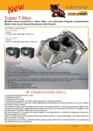
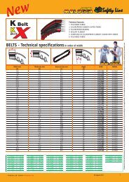
CAMBIO OLIO<br />
Smontare i due gambali della forcella dal trapezio allentando le viti che<br />
lo fissano e togliendo i tappi che hanno anche funzione di fermo (part. 1, Fig. 1)<br />
Capovolgere lo stelo per far defluire tutto l’olio presente al suo interno, prestando attenzione affinché la molla (part. 2, Fig.<br />
1) del gambale e gli eventuali distanziali (part. 3, Fig. 1) non escano dallo stelo e vadano smarriti.<br />
Rimontare il tutto come in origine e serrare a fondo tutte le viti.<br />
ENGLISH<br />
OIL CHANGE<br />
Disassemble the two fork stems from the trapezoid by loosening the fixing screws and removing the plugs that also serve<br />
for locking (part. 1, Fig. 1).<br />
Turn the fork rod over to drain all the oil present inside, paying attention to prevent the spring (part. 2, Fig. 1) of the stem<br />
and any spacers inserted (part. 3, Fig. 1) do not leave the fork rod and get lost.<br />
Reassemble everything as before and firmly tighten all screws.<br />
DEUTSCH<br />
ÖLWECHSEL<br />
Bauen sie die beiden Gabelholme aus der Brücke aus indem sie die Klemmschrauben lösen und die Haltestopfen aus den<br />
Holmen entfernen (Teil 1, Fig. 1).<br />
Drehen sie die Gabelholme um und lassen sie alles Öl ablaufen. Achten sie dabei darauf dass weder die Feder (Teil 2, Fig.<br />
1) des Holmes noch irgendwelche Spacer (Teil 3, Fig. 1) aus dem Holm fallen oder gar verloren gehen.<br />
Montieren sie alles in umgekehrter Reihenfolge, ziehen sie die Schrauben fest.<br />
22
1<br />
3<br />
F36R<br />
LIVELLO OLIO / OIL LEVEL / ÖLSTAND 40<br />
F32S<br />
2<br />
23
ITALIANO<br />
Forcella F32 S<br />
Tipo di olio usato Agip Arnica 46<br />
Classificazione SAE<br />
SAE15<br />
Quantità per stelo<br />
100cc<br />
Viscosità cst 40 °C 44<br />
Viscosità cst 100 °C 8,2<br />
Indice di viscosità 165<br />
Punto di scorrimento 0-28 °C<br />
Forcella F36 R<br />
Tipo di olio usato<br />
Bel-Ray SAE5 MC10<br />
Classificazione SAE<br />
SAE5<br />
Quantità per stelo<br />
160cc<br />
Viscosità cst 40 °C 25<br />
Viscosità cst 150 °C 20<br />
Indice di viscosità 100<br />
Punto di scorrimento 0-60 °C<br />
ENGLISH<br />
F32 S fork<br />
Type of oil used Agip Arnica 46<br />
SAE Rating<br />
SAE15<br />
Quantity per fork rod<br />
100cc<br />
Viscosity cst 40°C 44<br />
Viscosity cst 100°C 8,2<br />
Viscosity index 165<br />
Sliding point 0-28 °C<br />
F36 R fork<br />
Type of oil used<br />
Bel-Ray SAE5 MC10<br />
SAE Rating<br />
SAE5<br />
Quantity per fork rod<br />
160cc<br />
Viscosity cst 40°C 25<br />
Viscosity cst 150°C 20<br />
Viscosity index 100<br />
Sliding point 0-60 °<br />
DEUTSCH<br />
F32 S Gabel<br />
Empfohlenes Öl Agip Arnica 46<br />
SAE Rating<br />
SAE15<br />
Volumen pro Holm<br />
100cc<br />
Viskosität cst 40°C 44<br />
Viskosität cst 100°C 8,2<br />
Viskosität index 165<br />
Tropfpunkt 0-28 °C<br />
F36 R Gabel<br />
Empfohlenes Öl<br />
Bel-Ray SAE5 MC10<br />
SAE Rating<br />
SAE5<br />
Volumen pro Holm<br />
160cc<br />
Viskosität cst 40°C 25<br />
Viskosität cst 150°C 20<br />
Viskosität index 100<br />
Tropfpunkt 0-60 °C<br />
24
RICAMBI / SPARE PARTS / ERSATZTEILE F 32S F 32S F 32S F 32S F 36R F 36R<br />
KIT FORCELLA 46 9550 46 9552 46 9627 4613086 4613062 4613090<br />
fork kit, Gabel kit<br />
COMPLESSIVO SUPPORTO PARAFANGO 18 9555B 18 9555B 18 9555B - - -<br />
complete mudgard support, Satz Kotflügelhalterungen<br />
COMPLESSIVO PERNO DELLA RUOTA 19 9899 19 9900B 19 9900B 19 9900B 19 9901 19 9787B<br />
wheel axle kit, Achse<br />
COMPLESSIVO FASCETTE IN GOMMA 21 9547B 21 9547B 21 9547B 21 9547B 21 9815B 21 9815B<br />
rubber clamp kit, Satz Gummischellen<br />
COMPLESSIVO SUPPORTO PINZA FRENO ORIGINALE 18 9525 18 9525 18 9800B 18 9800B 1813088B 1813088B<br />
original braket caliper kit, Halterungssatz für Originalbremszange<br />
PINZA IDRAULICA ANTERIORE FRENO 62 8986 - - - - -<br />
front brake caliper, Bremszange vorne hydraulisch<br />
WHOOP DISC - - 6212605 6213073 6212605 6213073<br />
2 DISTANZIALI RUOTA - - - 0813083E - 0813271<br />
2 whell spacers , 2 Wellen Ausgleichscheiben<br />
FORCELLA 46 9133 46 9524 46 9524 4613079 46 9626 4613089<br />
fork, Gabel<br />
TRAPEZIO COMPLETO 4612837B 4613644 4613644 - 4612017 -<br />
complete fork bottom yoke, Trapezteil Kpl.<br />
GAMBALE DESTRO (DX) / SINISTRO (SX) (DX) 4611348B 4611348B 4611348B 4613078B 4612020B 4612020B<br />
fork shaft right / left, Tachrohr-Standrohreinheit rechts / links (SX) 4611349B 4611349B 4611349B 4613077B 4612019B 4612019B<br />
TUBO DI FORZA (LATO SINISTRO) 4611685B 4611685B 4611685B 4614045B 4613345B 4613345B<br />
inner tube (left side), Gabelstandrohr (links Seite)<br />
TUBO DI FORZA (LATO DESTRO) 4611686B 4611686B 4611686B 4614046B 4613346B 4613346B<br />
inner tube (right side), Gabelstandrohr (rechts Seite)<br />
PARAOLIO 6611231B 6611231B 6611231B 6611231B 6611232B 6611232B<br />
oil-seal, Wellendichtring<br />
MOLLA INTERNA 2912763B 2912763B 2912763B 2912763B 2912764B 2912764B<br />
inner spring, innere Feder<br />
KIT PARAOLIO / PARAPOLVERE 6611689 6611689 6611689 6611689 6614411 6614411<br />
oil-seal / dust-seal kit, Satz Dichtring / Staubring<br />
KIT O-RING PER REVISIONE 0612248 0612248 0612248 0612248 0612258 0612258<br />
O-ring overhaul kit, Reparatursatz O-Ringe<br />
25
ITALIANO<br />
Speriamo che lei abbia trovato sufficientemente esaustive le indicazioni che precedono. Nel caso in cui qualche punto le risultasse<br />
poco chiaro, potrà interpellarci per iscritto compilando l’apposito modulo inserito nella sezione “contatti” del ns. sito Internet (www.<br />
malossi.com).<br />
Ringraziamo fin d’ora per le osservazioni e suggerimenti che vorrà eventualmente farci pervenire.<br />
La Malossi si commiata e coglie l’occasione per complimentarsi ulteriormente con Lei ed augurarle un Buon Divertimento. In BOCCA<br />
al LUPO e ... alla prossima.<br />
Le descrizioni riportate nella presente pubblicazione, si intendono non impegnative. Malossi si riserva il diritto di apportare modifiche,<br />
qualora lo ritenesse necessario, al fine di migliorare il prodotto, e non si assume nessuna responsabilità per eventuali errori tipografici<br />
e di stampa. La presente pubblicazione sostituisce ed annulla tutte le precedenti riferite agli aggiornamenti trattati.<br />
ENGLISH<br />
We hope you found the above instructions sufficiently clear. However, if any points are not particularly clear, please contact us<br />
completing the special form inserted in the “contact” section on our Internet site (www.malossi.com).<br />
We thank you in advance for any comments and suggestions you may wish to send us.<br />
So goodbye from us all at Malossi, and please accept our compliments. Have Fun. GOOD LUCK and … see you next time.<br />
The descriptions in this publication are not binding. Malossi reserves the right to make modifications, if it considers them necessary,<br />
and does not accept any responsibility for any typographic or printing errors. This publication replaces all previous publications<br />
referring to the updating matters contained therein.<br />
DEUTSCH<br />
Wir hoffen, Ihnen mit den hier beschriebenen Anleitungen ausreichend Auskunft gegeben zu haben. Sollten Sie noch Fragen haben,<br />
so ersuchen wir Sie das spezielle Formular auf der “Kontakt” Seite auf unsererer Internetseite auszufüllen.(www.malossi.com).<br />
Wir danken Ihnen bereits im voraus für die an uns gerichteten Tipps und Anmerkungen.<br />
Malossi verabschiedet sich nun, wünscht Ihnen viel Spaß und Hals- und Beinbruch ... bis zum nächsten Mal.<br />
Die Beschreibungen in dieser Anleitung sind nicht bindend. Malossi behält sich das Recht vor, notwendige Änderungen durchzuführen<br />
und kann nicht für etwaige inhaltliche oder Druckfehler verantwortlich gemacht werden. Diese Anleitung ersetzt alle vorhergegangenen<br />
bezogen auf die erfolgten Änderungen darin.<br />
26
GARANZIA<br />
Egregio Signora/re, La ringraziamo vivamente per la preferenza accordataci con la scelta dei nostri prodotti.<br />
Il consenso della clientela é lo stimolo più importante per la creatività e l’efficienza di un’azienda.<br />
Ogni prodotto commercializzato dalla Malossi è pensato, progettato e concepito negli stabilimenti della casa madre con il preciso<br />
intento di soddisfare le attese dei motociclisti più esigenti che intendono dare una personalizzazione tecnica al proprio veicolo.<br />
L’alto livello tecnologico della produzione, la severità dei collaudi ed il controllo qualità certificati ISO 9001, garantiscono un grado di<br />
difettosità dei prodotti molto basso.<br />
Qualora il ns. prodotto dovesse presentare delle anomalie di funzionamento, pur essendo:<br />
- stato montato seguendo scrupolosamente le istruzioni di montaggio;<br />
- sottoposto ad un corretto rodaggio su di in veicolo in buone condizioni;<br />
- non associato a prodotti diversi da quelli originali o Malossi;<br />
WARRANTY<br />
Dear Sir/Madam, Thank you for choosing our products.<br />
Customer approval is the greatest form of encouragement a company can have for creativity and efficiency.<br />
Each Malossi product sold is conceived, designed and developed at the factories of the parent company with the precise aim of satisfying<br />
the needs of the most demanding motorcyclists who wish to race tune their vehicle.<br />
High-tech production, stringent testing and quality control certified to ISO 9001 all ensure a very low defective product rate.<br />
Should our product present defects in spite of having:<br />
- been assembled exactly as per the assembly instructions given;<br />
- undergone a correct running in procedure with the vehicle in good condition;<br />
- been fitted with either original or Malossi parts;<br />
you can look up our Internet site at www.malossi.com, where you will find all the correct technical information by examining the relative<br />
GARANTIE<br />
Sehr geehrter Kunde, vielen Dank für Ihre Wahl unseres Produkts. Die Zustimmung unserer Kunden ist die wichtigste Anregung für die<br />
Kreativität unserer Entwerfer, sowie des gesamten Unternehmens. Jedes von Malossi verkaufte Produkt wird in unserem Unternehmen<br />
mit der Absicht entworfen und konzipiert, den Erwartungen der anspruchsvollsten Motorradfahrer zu entsprechen, die eine technische<br />
Individualisierung ihres Fahrzeugs wünschen. Das hohe technologische Produktionsniveau, die strengen Abnahmen und die zertifizierte<br />
Qualitätskontrolle ISO 9001 garantieren einen extrem niedrigen Fehlergrad.<br />
Falls unser Produkt Funktionsstörungen aufweisen sollte, trotz:<br />
- Einer Montage unter genauer Befolgung der Montageanleitung;<br />
- Korrekten Einfahrens mit einem Fahrzeug in gutem Zustand;<br />
- Vermeidung der Kombination mit Produkten, die weder vom Hersteller, noch von Malossi stammen;<br />
können Sie auf unserer Internetseite www.malossi.com genaue technische Informationen mit Hinweisen für Ihr Fahrzeug finden.<br />
27
ITALIANO<br />
Lei potrà consultare il ns. sito internet www.malossi.com, dove troverà precise informazioni tecniche visualizzando le tavole relative<br />
al vs. veicolo. Se questo non fosse sufficiente, unitamente al suo meccanico, potrà esporre dettagliatamente il problema compilando<br />
l’apposito modulo inserito nella sezione “contatti” del ns. sito Internet.<br />
Se a seguito di uno o più colloqui si rivelasse necessario l’invio presso la nostra sede del prodotto oggetto del problema, perché sia<br />
sottoposto ad una verifica tecnica, la procedura da seguire sarà la seguente.<br />
Il punto vendita autorizzato Malossi presso il qual è stato effettuato l’acquisto curerà la spedizione, corredandola di tutti i dati<br />
necessari, scontrino fiscale compreso, mettendo in tal modo il nostro reparto di controllo qualità nelle condizioni di valutare<br />
l’eventuale difettosità e di risalire al lotto di produzione al quale appartiene il prodotto in oggetto.<br />
Qualora la garanzia fosse riconosciuta, sarà sostituita soltanto la parte difettosa che sarà trattenuta da noi.<br />
Qualora, invece, la garanzia non fosse riconosciuta, il prodotto in oggetto sarà in ogni modo rispedito al ns. punto vendita in porto<br />
assegnato, ovvero con la stessa modalità di spedizione che la Malossi segue anche in caso di riconoscimento della garanzia.<br />
ENGLISH<br />
DEUTSCH<br />
tables for your vehicle. If this is not enough you can, along with your mechanic, explain the problem in greater detail by completing<br />
the special form inserted in the “contact” section of our Internet site.<br />
If after one or two consultations it proves necessary to send the faulty product in question to our headquarters for technical<br />
assessment, the procedure is as follows.<br />
The authorized sales Malossi outlet where the vehicle was purchased will have it shipped back to us, along with all the necessary<br />
details, including the receipt, so that Quality Control can assess the existence of any defect and trace the vehicle’s production lot.<br />
If warranty approval is granted, only the faulty part (which will be retained by us) will be replaced.<br />
However, should the warranty not be approved, the product will be sent back to our sales outlet, carriage forward, the same shipment<br />
method used by Malossi when it approves a warranty.<br />
- Goods not purchased from our sales outlets cannot be returned to us.<br />
- Warranty approval will not be granted for any products which have been tampered with.<br />
Sollten diese Informationen nicht ausreichen, können Sie gemeinsam mit Ihrem Mechaniker das Problem detailliert beschreiben und<br />
das spezielle Formular auf der “Kontakt” Seite auf unsererer Internetseite ausfüllen.<br />
Sollte sich nach einer oder mehrerer Kontaktaufnahmen herausstellen, dass das betroffene Produkt zwecks technischer Prüfung an<br />
unser Unternehmen geschickt werden muss, ist folgendes Prozedere durchzuführen.<br />
Der autorisierte Malossi-Händler, bei dem Sie das Produkt gekauft haben, kümmert sich um die Spedition, nachdem Sie ihm die<br />
erforderlichen Daten und den Kassenbon übergeben haben.<br />
Auf diese Weise wird es unserer Qualitätskontrolle ermöglicht, den Fehler zu bewerten und die Produktionsserie des Produkts zu<br />
identifizieren.<br />
Wird die Garantie anerkannt, wird nur das von uns einbehaltene defekte Teil ersetzt.<br />
Bei Ablehnung der Garantie wird das Teil per Nachnahme an unseren Verkaufspunkt zurückgesendet, also mit dem gleichen<br />
Speditionsverfahren, nach dem Malossi auch bei anerkannter Garantie verfährt.<br />
28
- Non si accettano resi di merce non provenienti da nostri punti vendita.<br />
- La garanzia non è riconosciuta sui prodotti manomessi.<br />
- La garanzia si esaurisce nella sostituzione di quei particolari di nostra produzione da noi ritenuti difettosi per errori di lavorazione o altro<br />
e non copre eventuali danni al mezzo, a cose o a persone.<br />
- Decliniamo ogni responsabilità derivante dall’uso improprio dei nostri prodotti.<br />
Tutti i nostri prodotti sono destinati ad impieghi sportivi, essendo stati creati per i molteplici Trofei Internazionali, per uso privato e di<br />
noleggio.<br />
Come tutti i prodotti destinati alle competizioni, i prodotti Malossi devono essere considerati diversamente dai prodotti destinati all’impiego<br />
stradale e non possono sottostare alle leggi ed ai codici stradali delle diverse nazioni nei quali sono venduti.<br />
I prodotti Malossi appartenenti alla linea competizione MHR, sono prodotti selezionatissimi, costruiti con i materiali più prestigiosi, e sono<br />
destinati alle competizioni più esasperate.<br />
- The warranty becomes void if parts manufactured by us which we deem defective due to production errors or other circumstances are<br />
replaced, and does cover any damage to the vehicle or to property or persons.<br />
- We decline all responsibility for improper use of our products.<br />
The end use of all our products is for sports purposes, having been designed for many International Trophies, for private use and for<br />
hire.<br />
Like all products for competition purposes Malossi products must be considered differently to those destined for road use and cannot<br />
comply with the laws and highway codes of the different nations in which they are sold.<br />
Malossi products belonging to the MHR competition line, are highly select products, constructed using prestigious materials, and are<br />
destined for the toughest competitions.<br />
As such they are exempt from any form of warranty, except in the rare instance of a component which has escaped testing and has a real<br />
manufacturing defect from source; the warranty does not cover their failure through fatigue or seizure.<br />
- Waren die nicht von unseren Verkaufsstellen stammen, werden nicht angenommen.<br />
- Bei manipulierten Produkten verfällt die Garantie.<br />
- Die Garantie umfasst nur den Ersatz der Teile aus unserer Produktion, die durch uns aufgrund von Produktionsfehlern oder anderen<br />
Gründen als defekt anerkannt werden.<br />
Eventuelle Schäden an Fahrzeug, Gegenständen oder Personen sind von der Garantie ausgeschlossen.<br />
- Wir übernehmen keine Verantwortung bei unsachgemäßem Gebrauch unserer Produkte.<br />
Unsere Produkte sind für den Sportgebrauch vorgesehen und wurden für die zahlreichen internationalen Wettbewerbe, den Privatgebrauch<br />
und den Verleih geschaffen.<br />
Wie alle für Wettrennen bestimmte Artikel sind Malossi-Produkte nicht gleichzusetzen mit Ersatzteilen, die für den Gebrauch auf<br />
öffentlichen Straßen vorgesehen sind.<br />
Sie unterliegen nicht den Gesetzen und Straßenverkehrsverordnungen der Länder, in denen sie verkauft werden.<br />
29
ITALIANO<br />
Sono pertanto esclusi da ogni forma di garanzia, a meno che non si tratti di un caso rarissimo di un componente sfuggito al collaudo<br />
che rechi una reale difettosità produttiva all’origine e non una rottura per fatica o per grippaggio.<br />
Prodotti riservati esclusivamente alle competizioni nei luoghi ad esse destinate secondo le disposizioni delle competenti<br />
autorità sportive. Decliniamo ogni responsabilità per l’uso improprio.<br />
ENGLISH<br />
These products are reserved solely for races in locations reserved for those purposes and in accordance with the regulations<br />
issued by the competent authorities for sports events. We decline any and all responsibility for improper use.<br />
DEUTSCH<br />
Malossi-Produkte der Rennserie MHR sind hochwertige Produkte aus wertvollen Materialien, die für Rennen mit extremen<br />
Belastungen geschaffen wurden. Sie sind daher von jeglicher Garantie ausgeschlossen, es sei denn, es handelt sich um den sehr<br />
seltenen Fall einer Komponente, die durch die Abnahme übersehen wurde und die einen reellen Produktionsfehler aufweist, also<br />
keine Beschädigung durch Materialermüdung oder Verschleiß. Wir danken Ihnen für ihre freundliche Zusammenarbeit und verbleiben<br />
mit freundlichen Grüßen.<br />
Diese Produkte sind ausschließlich für Wettkämpfe an den hierfür nach den Vorschriften der zuständigen<br />
Sportaufsichtsbehörden vorgesehenen Austragungsstätten bestimmt. Bei zweckwidriger Verwendung besteht keine<br />
Haftung.<br />
30
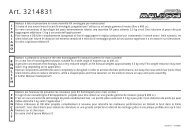
F32S KIT FORCELLA / <strong>FORK</strong> KIT / <strong>GABEL</strong> KIT<br />
art. 46 9550<br />
GILERA<br />
PIAGGIO<br />
Fig. 3<br />
STORM 50 2T<br />
TYPHOON / TYPHOON X 50 - 125 2T<br />
NRG 50 2T LC<br />
NRG EXTREME 50 2T / 50 2T LC<br />
NRG MC2 50 2T LC<br />
NRG MC3 DT 50 2T / DD 50 2T LC<br />
NRG Power DT 50 2T (C453M)<br />
NTT 50 2T LC<br />
TYPHOON 50 2T 2007-><br />
art. 4613086<br />
GILERA RUNNER PureJet 50 2T LC 2006-><br />
RUNNER SP (carb.) 50 2T LC 2006-> (C451M)<br />
RUNNER VX 125 4T LC 2006-><br />
RUNNER VXR 200 4T LC 2006-><br />
F36R KIT FORCELLA / <strong>FORK</strong> KIT / <strong>GABEL</strong> KIT<br />
art. 4613062<br />
GILERA<br />
RUNNER FX 125 2T LC<br />
RUNNER FXR 180 2T LC<br />
RUNNER VX 125 4T LC (C451M)<br />
RUNNER VX 125 4T LC 2006-><br />
RUNNER VXR 200 4T LC 2006-><br />
31
F32S KIT FORCELLA / <strong>FORK</strong> KIT / <strong>GABEL</strong> KIT<br />
art. 46 9552<br />
GILERA<br />
RUNNER 50 2T LC<br />
RUNNER PureJet 50 2T LC