OP3-OP5 - Automatizari pentru porti
OP3-OP5 - Automatizari pentru porti
OP3-OP5 - Automatizari pentru porti

You also want an ePaper? Increase the reach of your titles
YUMPU automatically turns print PDFs into web optimized ePapers that Google loves.
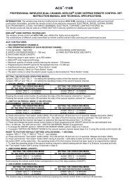
<strong>OP3</strong>-<strong>OP5</strong><br />
ATTUATORE LINEARE ELETTROMECCANICO PER CANCELLI A BATTENTE<br />
ISTRUZIONI E AVVERTENZE PER L`INSTALLAZIONE, L`USO E LA MANUTENZIONE<br />
LINEAR ELECTROMECHANICAL OPERATOR FOR SWING GATESСТВОРЧАТЫХ<br />
INSTRUCTIONS AND WARNINGS FOR INSTALLATION, USE AND MAINTENANCEОБСЛУЖИВАНИЮ<br />
ACTIONNEUR LINEAIRE ELECTROMECANIQUE POUR PORTAILS A<br />
INSTRUCTIONS ET CONSEILS POUR L’INSTALLATION, L’UTILISATION ET<br />
ACTUADOR LINEAL ELECTROMECÁNICO PARA CANCELAS<br />
INSTRUCCIONES Y ADVERTENCIAS PARA LA INSTALACIÓN, EL USO Y EL<br />
MOTOR LINEAR ELECTROMECÂNICO PARA PORTÕES DE BATENTE<br />
INSTRUÇÕES E ADVERTÊNCIAS PARA A INSTALAÇÃO, USO E A MANUTENÇÃO<br />
ELEKTROMECHANISCHER DREHTORANTRIEBСТВОРЧАТЫХ ВОРОТ<br />
ANLEITUNGEN UND HINWEISE FÜR INSTALLATION, GEBRAUCH UND WARTUNG<br />
МЕХАНИЗМ SIŁOWNIK LINEARNY ELEKTROMAGNETYCZNY DO BRAM<br />
INSTRUKCJA MONTAŻU, UŻYTKOWANIA I KONSERWACJIОБСЛУЖИВАНИЮ<br />
ЛИНЕЙНЫЙ ЭЛЕКТРОМЕХАНИЧЕСКИЙ ИСПОЛНИТЕЛЬНЫЙ<br />
ИНСТРУКЦИИ и РЕКОМЕНДАЦИИ ПО МОНТАЖУ, ИСПОЛЬЗОВАНИЮ И ТЕХНИЧЕСКОМУ<br />
ELEKTROMECHANIKUS KAROS MEGHAJTÁS SZÁRNYAS KAPUKHOZ<br />
UTASÍTÁSUK ÉS FIGYELMEZTETÉSEK TELEPÍTÉSHEZ, HASZNÁLATHOZ ÉS KARBANTARTÁSHOZ<br />
VERSIONE 29052008
14 MANUFACTURER’S DECLARATION OF CONFORMITY<br />
Declaration of<br />
conformity<br />
under Directive 98/37/EC, appendix II, part B (Manufacturer’s Declaration of CE Conformity).<br />
LIFE home integration<br />
Via 1 Maggio, 37<br />
31043 FONTANELLE (TV) – Italy<br />
declares that the following product:<br />
<strong>OP3</strong>-<strong>OP5</strong><br />
satisfies the essential requisites established in the following directives:<br />
• Low voltage directive 73/23/EEC and subsequent amendments,<br />
• Electromagnetic compatibility directive 89/336/EEC and subsequent amendments,<br />
• Radio and telecommunications equipment directive 1999/5/EC and subsequent amendments.<br />
and satisfies the following standards:<br />
• EN 12445:2000 Industrial, commercial and garage doors and gates – Safety in the usage of motorised doors – testing<br />
methods<br />
• EN 12453: Industrial, commercial and garage doors and gates – Safety in the usage of motorised doors - Requisites.<br />
• EN 60204-1:1997 Machinery safety – Electric equipment of the machine – Part 1: general rules.<br />
• EN 60950 Information technology equipment - Safety - Part 1: General requisites<br />
• ETSI EN 301489-3:2001 Electromagnetic compatibility for radio equipment and appliances.<br />
• EN 300220-3:2000 Radio equipment and systems – short band devices – Technical characteristics and testing methods for radio<br />
apparatus with a frequency of 25 to 1000 MHz and powers of up to 500mW.<br />
The Manufacturer also declares that it is not permitted for the abovementioned components to be used until such time as the system in which they are<br />
incorporated is declared conform to directive 98/37/EC.<br />
Fonta<br />
Position:<br />
Signature:<br />
Managing Director<br />
_________________
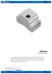
INSTALLAZIONE STANDARD<br />
STANDARD INSTALLATION<br />
INSTALLATION STANDARD<br />
INSTALACIÓN ESTÁNDAR<br />
INSTALAÇÃO STANDARD<br />
STANDARDINSTALLATION<br />
INSTALACJA STANDARDOWA<br />
ТАНДАРТНЫЙ МОНТАЖ<br />
ÁLTALÁNOS TELEPÍTÉSI RAJZ<br />
Tab. 1: Componenti e dispositivi di<br />
automazione tipo, vedi figura<br />
Tab. 1: Components and devices of a<br />
typical automation, see figure.<br />
Tab. 1 : Composants et dispositifs d’un<br />
automatisme type, voir figure.<br />
Tab.1: Componentes y dispositivos de un<br />
automatismo tipo, véase figura.<br />
Tab.1: Componentes e dispositivos de<br />
uma automatização tipo, ver figura.<br />
Tab.1: Bestandteile und Vorrichtungen<br />
eines Musterantriebs, siehe<br />
Abbildung.<br />
Tab.1: Części i urządzenia typowego<br />
siłownika, patrz obr..<br />
ТАБ.1: элементы и устройства для<br />
оборудования в стандартной<br />
комплектации см. рисунок<br />
Tab.1: általános automatikához tartozó<br />
robbantott rajz, lásd ábra.<br />
Tab. 2: Descrizione contenuto scatola attuatore<br />
OPTIMO, vedi figura<br />
Tab. 2: Description of the contents of the OPTIMO<br />
operator pack, see figure.<br />
Tab. 2 : Description contenu boîtier actionneur<br />
OPTIMO, voir figure.<br />
Tab. 2: Descripción del contenido de la caja del<br />
actuador OPTIMO, véase figura.<br />
Таб. 2: описание содержимого коробки<br />
исполнительного механизма OPTIMO, см.<br />
рисунок<br />
Tab. 2: Beschreibung des Verpackungsinhalts<br />
des Antriebs OPTIMO, siehe Abbildung.<br />
Tab.2: Opis zawartości opakowania OPTIMO,<br />
patrz obr..<br />
Таб. 2: описание содержимого коробки<br />
исполнительного механизма OPTIMO, см.<br />
рисунок<br />
Tab. 2: OPTIMO szetthez tartozó doboz tartalma<br />
, lásd ábra.<br />
OPTIMO<br />
OPTIMO<br />
Manuale di istruzioni<br />
Manuale di istruzioni<br />
AUTOMATIC DOOR OPENING
1 DATI TECNICI<br />
LIFE home integration si riserva il diritto di variare la caratteristiche tecniche in qualsiasi momento e senza preavviso, mantenendo la<br />
destinazione d’uso e la funzionalità.<br />
ITALIANO<br />
OPTIMO: Attuatore elettromeccanico irreversibile alimentato a 230 V o 24V per cancelli a battente con<br />
o senza enoder ottico,con o senza finecorsa elettrici, con finecorsa meccanici.<br />
NOME <strong>OP3</strong> <strong>OP3</strong> UNI <strong>OP3</strong>L <strong>OP3</strong>L UNI OP <strong>OP5</strong> UNI <strong>OP5</strong>L <strong>OP5</strong>L UNI <strong>OP3</strong>24 <strong>OP3</strong>24 UNI <strong>OP5</strong>24 <strong>OP5</strong> 24 UNI<br />
Alimentazione motore V 230 V a.c. 50 Hz 24V d.c.<br />
Potenza W 210 80<br />
Assorbimento A 1,3 3,5<br />
Condensatore µF 8 NO<br />
Spinta N 2000 1800<br />
Lubrificazione Tipo grasso<br />
Corsa utile stelo mm 300 450 300 450<br />
Termoprotezione °C 140 NO<br />
Finecorsa meccanico - SI - SI - SI - SI - SI - SI<br />
Finecorsa elettromeccanico SI - SI - SI - SI - SI - SI -<br />
Encoder ottico SI NO SI NO SI NO SI NO SI NO SI NO<br />
Cavo collegato CENELEC H07RN-F<br />
Temperatura di esercizio °C da -20 a +70<br />
Grado di protezione IP 54<br />
Velocità m/1’ 0,96 0,6 0,96 0,6 0,96 0,96<br />
Tempo per aprire di 90° s 19 30 28 45 19 28<br />
Ciclo di lavoro % 35 30 35 30 80 80<br />
Tempo di lavoro nominale min. 10 7,5 10 7,5 20 20<br />
Classe di isolamento motore F D<br />
Tempo ricarica batteria* h - 48<br />
Cicli apertura batteria carica N° - 15 10<br />
Peso attuatore Kg 8,5 9,5 8,5 9,5<br />
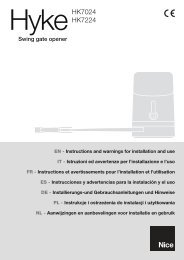
Dimensioni ingombro<br />
95x106 95x106 5x10⁶ 95x106<br />
L=860 L=1010 L=860 L=1010<br />
Utilizzo in atmosfera acida,salina o potenzialmente esplosiva<br />
NO<br />
2.0 INSTALLAZIONE<br />
2.1 Limiti d’impiego<br />
Il tipo di cancello, l’altezza e la forma delle ante, le condizioni climatiche determinano i limiti d’impiego; essi devono essere attentamente<br />
considerati nell’installazione. La tabella seguente ha valore solamente indicativo.<br />
1010<br />
860<br />
95<br />
D= <strong>OP3</strong> 775 mm<br />
106<br />
<strong>OP3</strong> corsa 300 mm<br />
D= <strong>OP5</strong> 905 mm<br />
<strong>OP5</strong> corsa 450 mm<br />
1
80<br />
E <strong>OP3</strong>= 745 mm<br />
E <strong>OP5</strong>= 895 mm<br />
<strong>OP3</strong> - <strong>OP3</strong>L - <strong>OP3</strong> UNI - <strong>OP3</strong>L UNI - <strong>OP3</strong>24 - <strong>OP3</strong>24 UNI<br />
<strong>OP5</strong> - <strong>OP5</strong>L - <strong>OP5</strong>UNI - <strong>OP5</strong>L UNI - <strong>OP5</strong>24 - <strong>OP5</strong>24 UNI<br />
Lunghezza max anta (m) Peso max anta (kg) Lunghezza max anta (m) Peso max anta (kg)<br />
2,00 800 3,00 500<br />
2,50 600 4,00 400<br />
3,00 400 5,00 300<br />
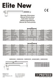
2.2 Installazione tipo<br />
A) IMPIANTO A DUE ANTE:La definizione di anta 1 e di anta 2 del cancello è fondamentale per il funzionamento dell’automazione:<br />
Anta 1: è la prima ad aprirsi (1) quando il cancello è chiuso, mentre è la seconda a muoversi quando si trova in posizione di ante aperte; arriva<br />
alla battuta di chiusura dopo l’anta 2.<br />
Anta 2: è la seconda ad aprirsi (2) quando il cancello è chiuso, mentre è la prima a muoversi quando si trova in posizione di ante aperte; arriva<br />
alla battuta di chiusura prima dell’anta 1.<br />
B) IMPIANTO AD UNA SOLA ANTA:<br />
Anta 1: l’unica anta del cancello.<br />
A<br />
1 2<br />
B<br />
1<br />
1<br />
2<br />
2<br />
2
Controllare che la quota “C” sulla struttura di sostegno del cancello non sia superiore al valore riportato nella tabella sottostante. Se la quota supera<br />
tale valore è necessario intervenire praticando un rientro nella struttura fino ad ottenere il valore indicato. Questo per evitare che in chiusura, l’attuatore<br />
lineare vada a sbattere contro lo spigolo della struttura. Il rientro deve essere praticato nella zona in cui sarà installato l’attuatore lineare e dovrà avere<br />
un’altezza tale da permettere il passaggio dell’attuatore.<br />
Ω<br />
<strong>OP3</strong> - <strong>OP3</strong>L - <strong>OP3</strong> UNI – <strong>OP3</strong>L UNI – <strong>OP3</strong>24<br />
<strong>OP3</strong>24 UNI<br />
<strong>OP5</strong> – <strong>OP5</strong>L – <strong>OP5</strong>UNI – <strong>OP5</strong>L UNI – <strong>OP5</strong>24<br />
<strong>OP5</strong>24 UN<br />
Amax Bmax Cmax D Amax Bmax Cmax D<br />
mm mm mm mm mm mm mm mm<br />
A<br />
E<br />
ITALIANO<br />
Ω1=90° 140 140 90 max 755 210 210 140 max 905<br />
Ω2=120° 140 100 50 max 755 210 120 70 max 905<br />
B<br />
C<br />
2.3 Posizionamento staffa posteriore e anteriore<br />
A<br />
a) Definire la posizione di fissaggio della staffa posteriore (1) dell’attuatore<br />
rispettando le quote A, B e C.<br />
b) Verificare che l’uscita del tubo di passaggio dei cavi elettrici venga a trovarsi<br />
sotto la staffa (1).<br />
c) Verificare che sull’anta, nel punto in cui deve essere fissata la staffa anteriore<br />
dell’attuatore, vi sia lo spazio necessario e la superficie adatta<br />
al fissaggio (con viti o tramite saldatura).<br />
d) Fissare (con viti o tramite saldatura) la staffa posteriore (1) al pilastro nella<br />
posizione stabilita.<br />
e) Verificare che la staffa posteriore (1) sia perfettamente in bolla.<br />
A<br />
D<br />
Ω<br />
1<br />
Ω<br />
2<br />
1<br />
1<br />
B<br />
2<br />
B<br />
C<br />
a. Portare l’anta in posizione di chiusura posandola<br />
alla battuta d’arresto meccanico di chiusura.<br />
b. Posizionare la staffa anteriore (2) alla distanza<br />
E dalla staffa posteriore più in basso di 80 mm.<br />
1<br />
OPTIMO 3 OPTIMO 5<br />
<strong>OP3</strong> - <strong>OP3</strong>L - <strong>OP3</strong> UNI – <strong>OP3</strong>L UNI <strong>OP5</strong> – <strong>OP5</strong>L – <strong>OP5</strong>UNI – <strong>OP5</strong>L UNI<br />
<strong>OP3</strong>24-<strong>OP3</strong>24UNI<br />
<strong>OP5</strong>-<strong>OP5</strong>L–<strong>OP5</strong>24 UNI<br />
E 745 mm 895 mm<br />
1<br />
C<br />
E<strong>OP3</strong>= 745<br />
E<strong>OP5</strong>= 895<br />
68<br />
2<br />
Il valore di E deve essere appena inferiore (10 mm) di D (interasse massimo) per permettere una migliore regolazione dei finecorsa.<br />
a) Bloccare provvisoriamente la staffa anteriore (2) con un morsetto.<br />
b) Verificare che la staffa sia in bolla.<br />
3
2.4 Posizionamento attuatore e regolazione finecorsa<br />
1. Effettuare lo sblocco dell’attuatore come indicato al cap. SBLOCCO ATTUATORE.<br />
2. Sollevare l’attuatore ed inserire il perno del supporto boccola madrevite (3) nel foro della staffa anteriore (2).<br />
3. Inserire la boccola (4) nel foro prescelto della staffa posteriore (1) e infilare la forcella dell’attuatore (5) sulla staffa, facendo coincidere il foro con la<br />
boccola. Fissare il tutto con vite, rondella e dado autobloccante chiudendo con forza.<br />
4. Fissare l’attuatore alla staffa anteriore (2) con vite e rondella, chiudendo con forza.<br />
5. Aprire e chiudere a ma<br />
piano di movimento del cancello.<br />
6. Controllare che il supporto boccola madrevite (3) scorra perfettamente sulla madrevite dell’attuatore e che, con anta chiusa e aperta, rimangano<br />
almeno 5 mm tra supporto boccola madrevite (3) e finecorsa di chiusura (7) e apertura (6).<br />
7. Se necessario, utilizzare un foro diverso sulla staffa posteriore ripetendo le operazioni indicate nei punti 3. e 4. .<br />
8. Definire con precisione le<br />
nel seguente modo:<br />
• portare il cancello in posizione di chiusura a battuta sull’arresto meccanico<br />
• allentare il supporto del finecorsa di chiusura (6) con apposita chiave e posizionarlo in modo da toccare il supporto boccola madrevite (3); quindi<br />
ribloccarlo stringendo la vite con forza.<br />
• Portare l’anta del cancello nella posizione di apertura desiderata;<br />
• allentare il supporto del finecorsa di apertura (7) con apposita chiave e posizionarlo in modo da toccare il supporto boccola madrevite (3); quindi<br />
ribloccarlo stringendo la vite con forza.<br />
9. Fissare in modo definitivo la staffa anteriore (2) dell’attuatore all’anta del cancello scegliendo i mezzi di fissaggio in base al materiale dell’anta<br />
(con viti o tramite saldatura).<br />
10. Ribloccare l’attuatore come indicato al cap. SBLOCCO ATTUATORE.<br />
1<br />
1<br />
4<br />
5<br />
5<br />
3<br />
2<br />
7<br />
3<br />
6<br />
2.5 Sblocco attuatore<br />
ATTENZIONE:<br />
• L’installatore deve fissare permanentemente l’etichetta concernente l’operazione di sblocco manuale vicino alla chiave per lo sblocco<br />
manuale.<br />
• L’attivazione dello sblocco manuale potrebbe causare un movimento non controllato del cancello a causa di danni meccanici o condizioni<br />
di sbilanciamento meccanico.<br />
• Prima di eseguire la manovra togliere l’alimentazione elettrica all’automazione.<br />
• Non far forza sulla chiave per evitare di romperla.<br />
Questo comando permette di sganciare la trasmissione dell’attuatore e di effettuare lo spostamento a mano dell’anta; può essere utilizzato in caso di<br />
mancanza di alimentazione o di anomalia dell’impianto.<br />
Lo sblocco è attuato tramite una chiave che deve essere conservata in un luogo sicuro.<br />
a) Sollevare il coperchietto (1) di protezione della serratura.<br />
2<br />
b) Infilare la chiave (2) nella serratura e ruotarla in senso orario di 360°<br />
360°<br />
BLOCCAGGIO<br />
c) Ora l’anta è libera e può essere movimentata a mano.<br />
d) Per ribloccare l’anta inserire la chiave (2)e ruotarla in senso antiorario<br />
di 360°.<br />
2<br />
1<br />
360°<br />
SBLOCCAGGIO<br />
4
3.0 ALLACCIAMENTI E COLLEGAMENTI<br />
• Prima di procedere agli allacciamenti e ai collegamenti leggere attentamente quanto riportato nel cap. PRESCRIZIONI E AVVERTENZE DI<br />
SICUREZZA.<br />
• L’attuatore deve essere collegato esclusivamente alle centrali di comando prodotta da Life:<br />
ITALIANO<br />
ATTAUTORI<br />
RICEVENTE RADIO AD<br />
INNESTO LIFE<br />
RICEVENTE RADIO<br />
433,92 MHz INTEGRATA<br />
230 V<br />
50 Hz<br />
<strong>OP3</strong> - <strong>OP3</strong>L - <strong>OP5</strong> - <strong>OP5</strong>L GE1A -GE2A GE1R -GE2R<br />
<strong>OP3</strong> UNI - <strong>OP3</strong>L UNI - <strong>OP5</strong> UNI - <strong>OP5</strong>L UNI<br />
GE UNI R<br />
24 V<br />
<strong>OP3</strong>24 - <strong>OP5</strong>24 GE1A 24 GE1A 24-GE2A 24<br />
<strong>OP3</strong>24 UNI - <strong>OP5</strong>24 UNI<br />
GE UNI 24R<br />
• Tutte l<br />
se il dispositivo di disconnessione non è a vista apporvi un cartello: “ATTENZIONE MANUTENZIONE IN CORSO”.<br />
• I cablaggi interni dell’attuatore lineare elettromeccanico che sono stati effettuati dall’azienda non vanno assolutamente modificati.<br />
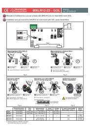
3.1 Collegamenti elettrici attuatore<br />
Dall’attuatore escono possono uscire uno o due cavi a seconda che si abbia o no la versione UNI.<br />
Le ve<br />
Le versioni con due cavi, sia a 230 V sia a 24 V, hanno in più il cavo per il segnale dell’encoder e dei finecorsa (cavo a 2 fili).<br />
Nei modelli a 230 V vi<br />
parallelo ai cavi “motore apre” e “motore chiude”.<br />
230 V<br />
50 Hz<br />
24 V<br />
ATTUATORI<br />
<strong>OP3</strong> - <strong>OP3</strong>L - <strong>OP5</strong> - <strong>OP5</strong>L<br />
<strong>OP3</strong> UNI - <strong>OP3</strong>L UNI - <strong>OP5</strong><br />
UNI - <strong>OP5</strong>L UNI<br />
<strong>OP3</strong>24 - <strong>OP5</strong>24<br />
<strong>OP3</strong>24 UNI - <strong>OP5</strong>24 UNI<br />
A<br />
B<br />
A<br />
B<br />
Nota: la lunghezza di ciascun cavo è pari ad 1 m.<br />
SEGNALE ENCODER<br />
E FINE CORSA<br />
ALIMENTAZIONE MOTORE<br />
MARRONE + C BLU / GRIGIO COMUNE<br />
BLU - D NERO MOTORE APRE<br />
E MARRONE<br />
MOTORE CHIUDE<br />
F GIALLO VERDE TERRA<br />
MARRONE + G BLU +<br />
BLU - H MARRONE -<br />
I GIALLO VERDE TERRA<br />
F<br />
C<br />
<strong>OP3</strong>-<strong>OP3</strong>L-<strong>OP5</strong>-<strong>OP5</strong>L<br />
D<br />
E<br />
<strong>OP3</strong> UNI-<strong>OP3</strong>L UNI<br />
<strong>OP5</strong> UNI-<strong>OP5</strong>L UNI<br />
I<br />
G<br />
H<br />
A<br />
B<br />
<strong>OP3</strong> 24-<strong>OP5</strong> 24<br />
F C<br />
D<br />
E<br />
<strong>OP3</strong>24 UNI-<strong>OP5</strong>24 UNI<br />
A<br />
B<br />
I<br />
G<br />
H<br />
5
DESCRIZIONE COMPONENTI OP/<strong>OP5</strong><br />
3<br />
DESCRIPTION OF <strong>OP3</strong>/<strong>OP5</strong> COMPONENTS<br />
DESCRIPTIONS PARTICULIERES<br />
<strong>OP3</strong> / <strong>OP5</strong><br />
DESCRIPCIONES DE LOS DETALLES<br />
DEL <strong>OP3</strong> / <strong>OP5</strong><br />
DESCRIÇÕES PARTICULARES <strong>OP3</strong> / <strong>OP5</strong><br />
BESONDERE BESCHREIBUNGEN<br />
<strong>OP3</strong> / <strong>OP5</strong><br />
OPIS SZCZEGÓŁOWY <strong>OP3</strong> / <strong>OP5</strong><br />
ОПИСАНИЕ ОСОБЕННОСТЕЙ <strong>OP3</strong> / <strong>OP5</strong><br />
<strong>OP3</strong>/<strong>OP5</strong> RÉSZLETEZETT ROBBANTOTT<br />
LEÍRÁSA<br />
1-2<br />
1) 5RI0870000 <strong>OP3</strong>-<strong>OP5</strong>-<strong>OP3</strong>UNI-<strong>OP5</strong>UNI<br />
2) 5RI0880000 <strong>OP3</strong>L-<strong>OP3</strong>LUNI-<strong>OP5</strong>L-<strong>OP5</strong>LUNI<br />
4-5<br />
3) 5RI0890000 <strong>OP3</strong>24-<strong>OP3</strong>24UNI-<strong>OP5</strong>24-<strong>OP5</strong>24UNI<br />
6<br />
4) 5RI0900000 <strong>OP3</strong>-<strong>OP3</strong>UNI-<strong>OP3</strong>L-<strong>OP3</strong>LUNI-<strong>OP3</strong>24-<strong>OP3</strong>24UNI<br />
5) 5RI0910000 <strong>OP5</strong>-<strong>OP5</strong>UNI-<strong>OP5</strong>L-<strong>OP5</strong>LUNI-<strong>OP5</strong>24-<strong>OP5</strong>24UNI<br />
7<br />
6) 5RI0920000 OPTIMO<br />
7) 5RI0930000 OPTIMO<br />
8<br />
9-10<br />
8) 5RI0940000 <strong>OP3</strong>-<strong>OP3</strong>L-<strong>OP5</strong>-<strong>OP5</strong>L-<strong>OP3</strong>24-<strong>OP5</strong>24<br />
11-12<br />
9) 5RI0950000 <strong>OP3</strong>-<strong>OP3</strong>L-<strong>OP3</strong>UNI-<strong>OP3</strong>LUNI-<strong>OP5</strong>-<strong>OP5</strong>L-<br />
<strong>OP5</strong>UNI-<strong>OP5</strong>LUNI<br />
10) 5RI0960000 <strong>OP3</strong>24-<strong>OP3</strong>24UNI-<strong>OP5</strong>24-<strong>OP5</strong>24UNI<br />
11) 5RI0970000 <strong>OP3</strong>-<strong>OP3</strong>L-<strong>OP3</strong>24<br />
12) 5RI0980000 <strong>OP5</strong>-<strong>OP5</strong>L-<strong>OP5</strong>24
13<br />
14<br />
13) 5RI0990000 OPTIMO<br />
14) 5RI1000000 OPTIMO<br />
15-16 17<br />
15) 5RI1010000 <strong>OP3</strong>-<strong>OP3</strong>L-<strong>OP3</strong>24<br />
16) 5RI1020000 <strong>OP5</strong>-<strong>OP5</strong>L-<strong>OP5</strong>24<br />
18<br />
17) 5RI1030000 OPTIMO<br />
19<br />
18) 5RI1040000 OPTIMO 19) 5RI1060000 OPTIMO<br />
20 21<br />
20) 5RI1070000 OPTIMO 22) 5RI1080000 <strong>OP3</strong>-<strong>OP3</strong>L-<strong>OP3</strong>UNI-<strong>OP3</strong>LUNI-<strong>OP5</strong>-<strong>OP5</strong>L<br />
<strong>OP5</strong>UNI-<strong>OP5</strong>LUNI<br />
22<br />
23<br />
22) 5RI1100000 OPTIMO<br />
23) 5RI2750000 <strong>OP3</strong>UNI-<strong>OP3</strong>LUNI-<strong>OP3</strong>24UNI-<strong>OP5</strong>UNI<br />
<strong>OP5</strong>LUNI-<strong>OP5</strong>24UNI
14 MANUFACTURER’S DECLARATION OF CONFORMITY<br />
Declaration of<br />
conformity<br />
under Directive 98/37/EC, appendix II, part B (Manufacturer’s Declaration of CE Conformity).<br />
LIFE home integration<br />
Via Sandro Pertini 3/5<br />
31014 COLL E UMBERTO (TV) Italy<br />
declares that the following product:<br />
<strong>OP3</strong>-<strong>OP5</strong><br />
satisfies the essential requisites established in the following directives:<br />
• Low voltage directive 73/23/EEC and subsequent amendments,<br />
• Electromagnetic compatibility directive 89/336/EEC and subsequent amendments,<br />
• Radio and telecommunications equipment directive 1999/5/EC and subsequent amendments.<br />
and satisfies the following standards:<br />
• EN 12445:2000 Industrial, commercial and garage doors and gates – Safety in the usage of motorised doors – testing<br />
methods<br />
• EN 12453: Industrial, commercial and garage doors and gates – Safety in the usage of motorised doors - Requisites.<br />
• EN 60204-1:1997 Machinery safety – Electric equipment of the machine – Part 1: general rules.<br />
• EN 60950 Information technology equipment - Safety - Part 1: General requisites<br />
• ETSI EN 301489-3:2001 Electromagnetic compatibility for radio equipment and appliances.<br />
• EN 300220-3:2000 Radio equipment and systems – short band devices – Technical characteristics and testing methods for radio<br />
apparatus with a frequency of 25 to 1000 MHz and powers of up to 500mW.<br />
The Manufacturer also declares that it is not permitted for the abovementioned components to be used until such time as the system in which they are<br />
incorporated is declared conform to directive 98/37/EC.<br />
C<br />
Position:<br />
Signature:<br />
Managing Director<br />
_________________
LOGO<br />
Numero verde<br />
Address: Via Sandro Pertini 3/5 31014 Colle Umberto<br />
(TV) Italia<br />
Telephone: + 39 0438 388592<br />
Telefax: + 39 0438 388593<br />
http www.homelife.it<br />
e-mail: info@homelife.it