GE UNIR DL - Automatizari pentru porti
GE UNIR DL - Automatizari pentru porti
GE UNIR DL - Automatizari pentru porti

You also want an ePaper? Increase the reach of your titles
YUMPU automatically turns print PDFs into web optimized ePapers that Google loves.
<strong>GE</strong> UNI R <strong>DL</strong><br />
<strong>GE</strong> UNI RS <strong>DL</strong><br />
<strong>GE</strong> <strong>UNIR</strong> <strong>DL</strong><br />
CONTROL UNIT FOR TWO-LEAF GATES<br />
INSTRUCTIONS AND WARNINGS FOR INSTALLATION, USE AND MAINTENANCE
i<br />
t<br />
e<br />
l<br />
a<br />
STANDARD INSTALLATION<br />
Tab. 1: Components and devices of a typical <strong>GE</strong> UNI R <strong>DL</strong> automation.<br />
Tab. 2: Description of the content of a <strong>GE</strong> UNI R <strong>DL</strong> control unit pack.<br />
<br />
<br />
<br />
<strong>GE</strong> UNI R <strong>DL</strong><br />
Centrale<br />
di comando per cancel a dueane<br />
Istruzioni<br />
avvertenzeperl`instalazione,<br />
`uso<br />
e l manutenzione<br />
1A
<strong>GE</strong> UNI R <strong>DL</strong><br />
1<br />
1<br />
2<br />
RG58-50ohm<br />
AERIAL<br />
1<br />
2<br />
6<br />
7<br />
8<br />
9<br />
10<br />
11<br />
12<br />
13<br />
14<br />
15<br />
16<br />
17<br />
18<br />
19<br />
20<br />
21<br />
22<br />
23<br />
24<br />
25<br />
L1<br />
N.C.<br />
N.O.<br />
N.O.<br />
N.O.<br />
N.C.<br />
N.C.<br />
12 Vac 15VA<br />
24 Vac 3W max<br />
CAPACITOR<br />
CAPACITOR<br />
230 Vac 25W max<br />
8<br />
9<br />
STEP<br />
PHOTO1<br />
PHOTO<br />
ELECTRIC LOCK<br />
INDICATOR LIGHT<br />
MOTOR2 OPEN<br />
COMMON MOTOR2<br />
MOTOR2 CLOSE<br />
MOTOR1 OPEN<br />
COMMON MOTOR1<br />
MOTOR1 CLOSE<br />
FLASHING<br />
230 Vac 40W max COUTESY LYGHT<br />
L2<br />
L1<br />
6<br />
OUTPUT 24 Vac 200 mA max<br />
230 Vac<br />
2<br />
6<br />
7<br />
10<br />
3<br />
6<br />
12<br />
15<br />
16<br />
4<br />
14<br />
16<br />
RX<br />
NC<br />
NO<br />
COM<br />
0V<br />
12V<br />
24V<br />
COM<br />
NO<br />
NC<br />
24 Vac 3w max<br />
TX<br />
0V<br />
12V<br />
24V<br />
230aV<br />
<br />
BLACK<br />
ORAN<strong>GE</strong><br />
BROWN<br />
BLUE<br />
5<br />
24<br />
230 Vac 40W max<br />
25<br />
6<br />
23<br />
25<br />
7<br />
13<br />
16<br />
3
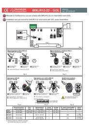
<strong>GE</strong>BOX ASSEMBLY INSTRUCTIONS.<br />
1<br />
2<br />
4<br />
3<br />
mm.<br />
184<br />
min cm 40<br />
mm.<br />
250<br />
5<br />
3A
PROGRAMMING THE CONTROL UNIT<br />
DEFINING THE STOP PLATES<br />
Ensure that the automation’s opening and closure stop plates have been fixed.<br />
PHASE 1<br />
1 2<br />
3<br />
OFF<br />
OFF<br />
OFF<br />
ON<br />
ON<br />
ENGLISH<br />
230V<br />
230V<br />
230V<br />
N.B. In case just one motor is utilised, choose from Menu Options 2 “Activate single motor” and connect on terminals 20-21-22<br />
PHASE 2<br />
<br />
<br />
<br />
<br />
<br />
<br />
PROGRAMMING THE TRAVEL<br />
a) Position the leaf gates at 45°.<br />
<br />
1 2<br />
<br />
<br />
<br />
<br />
<br />
<br />
<br />
<br />
b) Press for 5 seconds, the 5 LEDs will light and<br />
then start flashing.<br />
c) Press and the gate starts rolling, if it opens<br />
press again to invert the movment.<br />
The first activated limit switch has to be the one of the<br />
closing system.<br />
Finished the two flash programming<br />
green LED will be lit and a steady light led the two<br />
reds.<br />
If the result was not satisfactory, you can<br />
perform a programming manual to determine the<br />
lags. See Section 3.3.4<br />
PHASE 3<br />
<br />
<br />
AACKNOWLEDGMENT OF THE TOTAL OPENING RADIOCOMMAND<br />
<br />
<br />
<br />
<br />
P1<br />
P2<br />
<br />
<br />
<br />
<br />
a) Press , the green led (SX) will light and the red one A will<br />
switch on.<br />
b) Hold down the key (P1) on the radio control until all five LEDs<br />
light .<br />
c) Wait 25 seconds or press two times again to quit.<br />
<br />
<br />
<br />
ACKNOWLEDGMENT OF THE PEDESTRIANS’ OPENING<br />
RADIOCOMMAND<br />
a) Press , two times, the green (left) and the red (right)<br />
led switch on.<br />
b) Keep the button (P2) pushed untile all the five leds switch on<br />
.<br />
<br />
<br />
The automation is now programmed.<br />
SEMIAUTOMATIC mode is enabled: by giving the ‘STEP’ command, the automation changes movement following the sequence 1 – OPEN 2 – STOP 3 –<br />
CLOSE 4 – STOP. Automatic re-closure is not enabled.<br />
Once programming is complete, the<br />
key acts as a STEP command.<br />
1
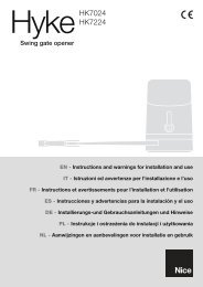
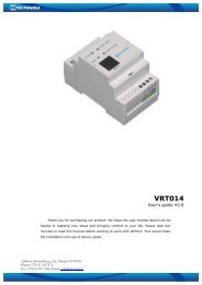
1 Wiring diagram of the right hand side of the control unit<br />
Fig. 7 shows a diagram of the connection terminals for the aerial, various controls and the various power supplies (indicator light, electrolock,<br />
flashing light, courtesy light, photocells, selectors, etc.). . These are the vertical terminals positioned on the right hand side of the control unit and<br />
numbered from 1 to 19.<br />
Terminals<br />
Description<br />
1 - 2 Aerial: aerial cable input 1 sheath, 2 cables. Use a RG58- 50ohm cable<br />
6 Common: for stop, open, close, step and photo inputs.<br />
6 - 7 STOP*: programmable NC input, commands gate stoppage. Can be connected to safety devices such as an emergency stop button.<br />
When the command is released automatic closure never occurs and a new movement command must be given.<br />
Leave jumpered if no device is envisaged<br />
6 - 8 OPEN: NO input, commands gate opening.<br />
6 - 9 CLOSE: NO input, commands gate closure.<br />
6 -10 STEP: NO input, commands gate movement according to the following cycles:<br />
SEMI-AUTOMATIC MODE: Open, stop, close, stop.<br />
4-STEP MODE Open, pause, close, pause.<br />
4-STEP with stop : OPEN-STOP-CLOSE-STOP<br />
CONDOMINIUM MODE: Open.<br />
6 -11 PHOTO 1*: programmable NC input for photocells or safety devices. Causes gate stoppage during both opening and closure. Motion<br />
resumesduring opening when the photocell or safety device is disengaged.Leave jumpered if no device is envisaged.<br />
PHOTO: NC input for photocells or safety devices. Does not intervene during gate opening; during closure causes reversal of gate motionuntil open.<br />
6 - 12<br />
Leave jumpered if no device is envisaged.<br />
16 - 13 ELECTROLOCK 12 V ac output for connection of the 12 Vac 15 VA electrolock.<br />
16 - 14<br />
INDICATOR LIGHT: 24Vac 3W max output, for connecting an indicator light that copies the function of the flashing light during movement<br />
and that remains on when the gate is open.<br />
16 - 15 24 V ac OUTPUT : power supply for various devices, 200 mA max.<br />
16 ELECTROLOCK, INDICATOR LIGHT AND 24 V ac OUTPUT COMMON.<br />
17 PHASE 1, CAPACITOR<br />
18 COMMON OPERATOR 2 POWER SUPPLY: 230 Vac 50 Hz output 300 W max.<br />
19 PHASE 2, CAPACITOR<br />
20 FASE 1, CONDENSATORE<br />
21 COMMON OPERATOR 1 POWER SUPPLY: 230 Vac 50 Hz output 300 W max.<br />
22 FASE 2, CONDENSATORE<br />
23 - 25 FLASHING LIGHT: 230 Vdc 25W max output for connecting a SPLENDOR SRL flashing light characterised by three flashing modes:<br />
1) slow during door opening; 2) fast (flashing times halved) during closure. 3) three flashes and a pause to indicate a fault state or travel identification.<br />
24 - 25<br />
COURTESY LIGHT: 230 Vdc 40W max. output for connecting a courtesy light that switches on at the start of each movement (opening<br />
or closure) and is characterised by an adjustable on time.<br />
-<br />
25 FLASHING OR COURTESY LIGHT POWER SUPPLY COMMON.<br />
L 1<br />
L 2<br />
230Vac 50Hz POWER SUPPLY, fusable input L2.
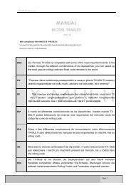
1.2 List of electric cables<br />
The cables needed may vary depending on the installation and type and quantity of devices installed.<br />
The cables used in the installation must be IEC 60335 compliant.<br />
Pos.<br />
Connection<br />
Type of cable<br />
ATTENTION: the cables used must be suited to the type of installation.<br />
It is the Fitter’s responsibility to choose appropriate material.<br />
Electricity supply line<br />
Power supply<br />
Flashing light<br />
Radio aerial<br />
Tx Photo<br />
Rx Photo<br />
Selector<br />
3x1,5 mm 2 cable<br />
Cable supplied with Schuko socket<br />
2x1 mm 2 cable<br />
Screened RG58 50 Ω cable<br />
2x1 mm 2 cable<br />
4x1 mm 2 cable<br />
3x1 mm 2 cable<br />
Internal button panel.<br />
3x1 mm 2 cable<br />
• Use the power supply cable provided with the operator only.<br />
• The power cable provided may not be extended or shortened<br />
Sensitive strip (signal)<br />
2x1 mm 2 cable<br />
• All wires must be unsheathed as little as possible (6mm at the most), as close as<br />
possible<br />
to the connection terminals, in order to prevent accidental contact with live parts should the<br />
cables disconnect from the terminals.<br />
• Do not pre-seal cables to be fastened to the terminals using screws.<br />
• If it is possible that wires subject to voltage higher than 50 Volt RMS and very low voltage<br />
safety wires may come into contact with one another, wires with voltage higher than 50 volt RMS must be insulated with a sheath; or the very low<br />
voltage safety wire must have an insulating sheath at least 1mm thick.<br />
• No external connection cables must be of the flat twin tinsel cord type.<br />
1.2.1 Setting up the electric system and connection to the mains supply<br />
This manual does not describe how the electrics system should be prepared for connection to the mains. It does, however, give the following warnings:<br />
• The electricity supply line must be installed and connected by an authorised electrician or professional fitter.<br />
• The electricity supply must be adequately protected against short circuits and static discharge.<br />
• The power supply network must contain an omnipolar circuit breaker with a contact opening distance equal to or greater than 3.5 mm that<br />
assures the complete disconnection of the power supply.<br />
1.2.3 Control unit connections<br />
Fitters must make the connections of the 230 Vac 50 Hz electricity supply, and the various automation devices.<br />
Connections between the control unit, motor, encoder and transformer have already been performed by the Manufacturer.<br />
• Once the connections to the control unit have been made, the Fitter must use bands to join adjacent wires into groups of 2, 3 or 4 in order to prevent<br />
them coming away from the terminal board: bands must be attached as close as possible to the terminals, no more than 10mm away, taking care not<br />
to damage wire insulation. No cable may remain unpaired.<br />
• The bands are only for unsheathed cables (sheathed cables are held in place by the sheath).<br />
• Pay careful attention not to pair wires with voltages higher than 50 Volt RMD with lower voltage wires.<br />
• The wiring performed internally by the manufacturer is already equipped with clamping bands.<br />
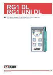
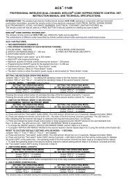
1.7.3 Indicator LEDs<br />
There is a row of 6 LEDs on the right hand side of the board, under the terminals.<br />
the NC inputs, stop and photo, the corresponding LEDs L7, L11 and L12 are<br />
normally lit; for the NO inputs open, close and step, the corresponding LEDS<br />
L8, L9 and L10 are normally off. These LEDs therefore indicate any malfunction<br />
of the connected devices.<br />
L7<br />
L8<br />
L9<br />
L10<br />
L11<br />
L12
2 RADIO CONTROL MANA<strong>GE</strong>MENT<br />
The control unit is fitted with a built-in radio receiver with a 1 channel 1000-code memory, with a 433.92 MHz frequency with LIFE Rolling<br />
Code and Auto code encoding.<br />
2.1 Resetting an initialised radio control<br />
<br />
<br />
<br />
<br />
a) Press , for 5 seconds, the green LED will light and<br />
then start flashing.<br />
P<br />
<br />
<br />
b) Hold down the key on the radio control until all five LEDs<br />
light<br />
, the remote control has been reset.<br />
ENGLISH<br />
c) Wait 25 seconds or press again to quit.<br />
2.2 Resetting all identified radio controls<br />
<br />
<br />
<br />
<br />
<br />
<br />
<br />
<br />
a) Press for 5 seconds, the green LED will light and<br />
then start flashing.<br />
b) Press for 5 more seconds , the first two and the<br />
last two LEDs will flash alternatively<br />
.<br />
After alternate flashing all initialised remote controls are reset.<br />
c) Attendere 25 secondi o premere nuovamente per uscire.<br />
3 ADJUSTMENTS<br />
3.1 Function modes<br />
There are 3 different operation modes that can be selected, SEMI-AUTOMATIC, AUTOMATIC RECLOSURE and CONDOMINIUM.<br />
The selection of one mode excludes the others.<br />
3.1.1 Semi-automatic<br />
Present by default after control unit programming.<br />
In this mode, by pressing the ‘STEP’ command, the automation changes its motion according to the sequence 1 – OPEN 2 – STOP 3 – CLOSE 4 - STOP;<br />
for example, if the automation is opening and one selects the step command on the remote control, the automation stops; conversely, if the automation<br />
is closed, when the step command is given it opens.<br />
Automatic re-closure is not enabled.<br />
OPEN » STOP » CLOSE » STOP<br />
5
3.1.2 Automatic reclosure<br />
Automatic reclosure is activated after a preset PAUSE TIME.<br />
In this mode, by pressing the ‘STEP’ key, the automation changes its motion according to the sequence 1 – OPEN 2 – PAUSE 3 – CLOSE 4 - PAUSE;<br />
for example, if the automation is opening and one selects the step command on the remote control, the automation stops in pause; conversely, if the<br />
automation is closed, when the step command is given it opens. PAUSE TIME is intended as the pause time before automatic re-closure.<br />
<br />
<br />
<br />
<br />
<br />
<br />
<br />
<br />
<br />
<br />
<br />
<br />
<br />
<br />
Press the green LED (RIGHT) switches on:<br />
• if none of the LEDs is switched on, automatic<br />
reclosure is not enabled, to enable it press ;<br />
• if at least one of the LEDs<br />
is switched on,<br />
automatic reclosure is enabled, to deactivate it press<br />
until all the LEDs switch off.<br />
Press and to set the various PAUSE TIME values.<br />
Wait 25 seconds or press<br />
again to quit.<br />
<br />
<br />
<br />
<br />
<br />
<br />
LEDS ON<br />
<br />
<br />
<br />
<br />
<br />
<br />
<br />
<br />
<br />
<br />
<br />
PAUSE TIME<br />
AUTOMATIC RE-CLOSURE IS NOT ENABLED<br />
5 s<br />
10 s<br />
30 s<br />
60 s<br />
120 s<br />
3.1.3 Menù Options 1<br />
Press to enter the menu options 1, press in sequence to go forward in the selection. The flashing of a LED indicates the position;<br />
with button ‘+’, the function is activated (red LED stays ON), with button ‘-’, the function is deactivated.<br />
LEDS OPTIONS 1<br />
No function is active.<br />
Residential : The automation closes automatically after the<br />
set PAUSE TIME<br />
Functioning mode as OPEN – STOP – CLOSE – STOP.<br />
Activation of the electrolock.<br />
Input STOP becomes FOTO2, the photocell is activated<br />
also for the opening phase<br />
,<br />
When gate has been opened, after passing between the<br />
photocells the gates will close<br />
3.1.4 Menù Options 2<br />
Press 5” to enter menu OPTIONS 2, press in sequence to go forward in the selection. The flashing of a LED indicates the position;<br />
with button ‘+’, the function is activated (red LED stays ON), with button ‘-’, the function is deactivated.<br />
LEDS<br />
OPTIONS 2<br />
No function is active.<br />
Deceleration when reaching end points<br />
5”<br />
Activate extra-stroke on closing and opening.<br />
Preflashing<br />
Single motor activated (connect on terminals 20-21-22)<br />
Soft Start
3.2.3 Force<br />
The force function regulates the thrust and the speed of the automation.<br />
<br />
<br />
<br />
<br />
<br />
<br />
Press the red LED (LEFT) switches on.<br />
Press and to set the various force values.<br />
ENGLISH<br />
<br />
Wait 25 seconds or press<br />
again to quit.<br />
<br />
<br />
<br />
<br />
<br />
<br />
<br />
LEDS ON<br />
<br />
<br />
<br />
<br />
<br />
<br />
<br />
<br />
<br />
<br />
<br />
<br />
FORCE VALUE<br />
Minimum<br />
Maximum<br />
3.2.4 Obstacle detection<br />
The automation is fitted with an obstacle detection system: the automation inverts its movement when it strikes an obstacle during the opening and<br />
closure phases.<br />
Sensitivity regulation consists in greater or lesser rapidity in response to the obstacle.<br />
1) During the closure phase, if the control unit identifies an obstacle, the automation inverts motion and performs complete opening. If the obstacle is<br />
detected 3 times consecutively, the automation stops in a completely open position awaiting a command.<br />
2) If the control unit identifies an obstacle, the automation performs a short reversal of motion, before stopping awaiting a command.<br />
Wait 25 seconds or press<br />
<br />
<br />
<br />
<br />
<br />
again to quit.<br />
<br />
<br />
then switch off.<br />
Press and to set the various obstacle detection values.<br />
Press for 5 seconds, the red LED (LEFT) will light and<br />
<br />
LEDS ON OBSTACLE DETECTION<br />
<br />
<br />
<br />
<br />
<br />
<br />
<br />
<br />
<br />
<br />
<br />
<br />
<br />
<br />
<br />
<br />
<br />
<br />
NO OBSTACLE DETECTION<br />
MINIMUM<br />
MAXIMUM<br />
3.3 Fuses<br />
Two internal fuses:<br />
a) F1 is turned on the secondary 24v supply, to protect the overload of the trasformator.<br />
Technical characteristics: mini fuses 5x20 T10 A certificated by IEC 60127 or EN 60127.<br />
b) F2 is turned on the primary 24v supply, to protect the overload of the motors.<br />
Technical characteristics: mini fuses 5x20 T1 A certificated by IEC 60127 or EN 60127.
3.3.4 Programming Manual<br />
Position the leaf gates at 45°<br />
a) Press for 5 seconds, the first 5 leds light up and<br />
after flash<br />
The programming can be done manually with a button<br />
connected to terminals 6-10 STEP BY STEP or the radio<br />
previously stored.<br />
LEARNING LIMIT CLOSING<br />
1 2 1 2<br />
a) Learning door closing switch 2. Give the command<br />
step (A) the door (2) reaches and is pushing for a moment the<br />
switch<br />
closing. When the door (2) learned of the switch closure<br />
remains on only the red LED (DX).<br />
b) Learning end closing door 1st Giving back<br />
the command step (A) reaches the door and push for a<br />
moment the<br />
switch closure. If the switch closure has been learned<br />
successfully remain on the central lit only red LED.<br />
SFAS OPEN<br />
1 2 1 2 1 2<br />
a) Give the command step (A) and release the shutter (1)<br />
opens. Al reaching the point where you want to open the<br />
door (2)<br />
Opening lag to the command step (A) and release it:<br />
the door (2) opens.<br />
b) The two doors shall open now and until reaching<br />
pushing for a moment their opening switches. If the<br />
Opening switches have been properly learned about Central<br />
remain turned on only the red LEDs.<br />
LEARNING SFAS CLOSING.<br />
1 2 1 2 1 2<br />
a) Give the command step (A) and release the shutter (2) closes.<br />
Al reaching the point where you want to quit<br />
the door (1) (delay of closure) to the command step (A)<br />
the door (1) closes. The two proceed hours before closing<br />
until reaching and pushing for a moment the respective switches<br />
closing.<br />
b) When both the doors (1) and (2) reached the end of<br />
closing to verify that flashing the two green LEDs and are fixed<br />
the two red LEDs.<br />
Automation is now planned. Automation is placed by default in<br />
semiautomatic mode.<br />
If the result is not satisfactory to reset the power and start over from scratch.
5 <strong>GE</strong>NERAL INFORMATION<br />
It is strictly forbidden to copy or reproduce this instruction manual without written permission to do so and subsequent verification by LIFE home integration. Translation into other languages of all or part<br />
of the manual is strictly forbidden without previous written authorisation from and subsequent verification by LIFE home integration. All rights on this document are reserved.<br />
LIFE home integration will not accept responsibility for damage or malfunctions caused by incorrect installation or improper use of products and Users are therefore recommended to read this manual<br />
carefully LIFE home integration will not accept responsibility for damage or malfunctions caused by the use of the automation together with the devices of other manufacturers; such action will render the warranty void.<br />
LIFE home integration will not accept responsibility for damage or injury caused by non-compliance with the installation, set up, maintenance and use indications contained in this manual and the safety<br />
instructions described in the SAFETY INSTRUCTIONS AND WARNINGS chapter.<br />
With the aim of improving its products, LIFE home integration reserves the right to bring about alterations to them at any time, without giving prior notice. This document conforms to the state of the<br />
automation at which it is provided when released for sale.<br />
ENGLISH<br />
5.1 INFORMATION ON THE MANUFACTURER<br />
LIFE home integration is the manufacturer of the RG1 24<strong>DL</strong> control unit (referred to for short as “control unit”) and the owner of all rights concerning this document.. The Manufacturer’s information as<br />
required by Machinery Directive 98/37/EC is given below:<br />
• Manufacturer: LIFE home integration<br />
• Address: Via S.Pertini,3/5 – 31014 COLLE UMBERTO (TV) Włochy<br />
• Telephone: + 39 0422 809 254<br />
• Fax: + 39 0422 809 250<br />
• http: www.homelife.it<br />
• e-mail: info@homelife.it<br />
The identity plate bearing the information on the Manufacturer is fixed to the control unit. The plate specifies the type and date (month/year) of manufacture of the product.<br />
For further information on technical and/or commercial issues and technician call-out and spares requests, Clients may contact the Manufacturer or area representative from which the product was purchased.<br />
5.2 INTENDED USE<br />
• The RG1 <strong>UNIR</strong> <strong>DL</strong>control unit has been exclusively designed to command 1 electromechanical operator with 230 Vac power supply destined to motorising ‘residential’ type leafs. Any<br />
usage differing from that described above is forbidden.<br />
• The control unit may only be used with other LIFE products.<br />
• The manufacturer declines all responsibility for damage caused by improper use. All risks are the fitter’s responsibility and the warranty shall be rendered void.<br />
• The control unit may not be installed or used in potentially explosive environments.<br />
• Motorised gates must conform to current European standards and Directives, including EN 12604 and EN 12605.<br />
• The control unit may only be used when in perfect working order and in compliance with the intended use, in the awareness of safety and hazard conditions and in compliance with the instructions for<br />
installation and use.<br />
• Any dysfunctions that may pose threats to safety must be eliminated immediately.<br />
• The control unit may not be used in environments prone to flooding.<br />
• Do not use the operator in environmental conditions characterised by harsh atmospheric agents (e.g. salty air).<br />
6 SAFETY INSTRUCTIONS AND WARNINGS<br />
6.1 General instructions and warnings<br />
• This manual is designed for use by PROFESSIONAL FITTERS only. Installation of the control unit requires practical and theoretical knowledge of mechanics, electrics and electronics<br />
as well as current sector legislation and regulations.<br />
• Once the control unit has been installed, it is forbidden for users to perform any operation on the control unit even following the instructions in this manual, which, as mentioned previously,<br />
are intended for use by qualified personnel only.<br />
• Fitters must operate in compliance with the following: law 46/90, directive 98/37/EC, 73/23/EEC, 89/336/EEC and subsequent amendments. He/she must also make constant reference to<br />
harmonised standards EN 12453 and EN 12445.<br />
• The indications given in this manual must always be observed when installing, connecting, adjusting, testing and setting the control unit. The Manufacturer declines all responsibility for<br />
damage or injury caused by non-observance of the instructions contained in this manual.<br />
• The Manufacturer declines all responsibility for damage and faults to the control unit caused by non-observance of the instructions contained in this manual.<br />
• Keep this manual in a safe and easily accessible place so that it can be consulted rapidly when necessary.<br />
• During installation, connection, trial run and usage of the control unit, observe all applicable accident prevention and safety regulations.<br />
• In the interests of safety and optimal functioning of the control unit, only use original spares, accessories, devices and fastening apparatus.<br />
• Do not perform alterations on any control unit device or component. This type of operation may cause malfunctions. The manufacturer declines all responsibility for damage caused by products that<br />
have been modified.<br />
• Should liquids penetrate inside the control unit, disconnect the electricity supply and contact the Manufacturer’s Assistance Service immediately; use of the control unit in such conditions may cause hazard situations.<br />
• In the event of long periods of inactivity, in order to prevent the leakage of harmful substances from the battery (optional), it should be removed, stored in a dry place and recharged periodically.<br />
• In the case of faults or problems that cannot be resolved using the information contained in this manual, contact the Manufacturer’s assistance service.<br />
6.2 Storage instructions and warnings<br />
• The Manufacturer declines all responsibility for damage and faults to control unit functioning caused by non-compliance with the storage instructions given below.<br />
• The control unit must be stored in closed, dry places, at room temperatures of between –20 and +70°C and raised off the ground.<br />
• Keep the control unit away from sources of heat and naked flames, which could damage it and cause malfunctions, fires or hazard situations.<br />
7 INSTALLATION<br />
ATTENTION: Important safety instructions. Follow all instructions carefully, incorrect installation may cause serious injury.<br />
Before commencing installation we highly recommend reading the instructions and warnings contained in this manual carefully (see the SAFETY INSTRUCTIONS AND WARNINGS Chap) and observing<br />
the instructions it contains.<br />
7.1 Instructions and warnings for installations<br />
• Before commencing installation read the. SAFETY INSTRUCTIONS AND WARNINGS chapter carefully<br />
• The PROFESSIONAL FITTER who installs the control unit is responsible for performing risk analysis and regulating the automation’s safety devices consequentially.<br />
• The Fitter must check that the temperature range declared on the control unit is suited to the place in which the device is installed.<br />
• Any normally open/off buttons installed for the activation of the operator must be positioned so that they are within view of the gate but distant from moving parts. Unless said commands<br />
operate using keys, they must be positioned at a minimum height of 1.5m and not accessible to unauthorised persons.<br />
• During installation, make constant reference to harmonised standards EN 12453 and EN12445.<br />
• Ensure that the individual devices to be installed are compatible with the RG1 <strong>UNIR</strong> <strong>DL</strong> control unit. Do not proceed if even just one device is unsuitable for the intended use.<br />
• Ensure that the place of installation of the central unit is not prone to flooding, does not contain sources of heat or naked flames, fires or hazard situations in general.<br />
• During installation, protect control unit components in order to prevent liquids (e.g. rain) and/or foreign bodies (earth, gravel, etc) penetrating inside.<br />
• Connect the control unit to a power supply line created in compliance with current regulations and earthed and fitted with a power supply sectioning switch.<br />
• Wrapping materials must be disposed of in compliance with local regulations.<br />
• Wear protective goggles when making holes for clamping.<br />
In the event of work at heights of over 2m from the ground, for example for the installation of the indicator lamp or aerial, fitters must be equipped with ladders, safety harnesses, protective helmet, and<br />
all other equipment required by law and the standards governing this kind of work. Refer to Directive 89/655/EEC amended by 2001/45/EC.<br />
9
8 TESTING AND TRIAL RUN<br />
• The testing and trial run must be performed by a COMPETENT PERSON supervised and aided by a PROFESSIONAL FITTER. It is the responsibility of the person who tests and sets up<br />
the automation (of which the control unit is a part) to perform the checks required in accordance with the risks existing and to check conformity with the relevant legislation and standards,<br />
in particular with EN standard 12445, which governs the methods for performing trials on gate automations and EN standard 12453 that specifies the performance requisites concerning safety of use.<br />
• The testing and trial run are the most essential phases of installation for guaranteeing maximum operating safety.<br />
• The checks and procedures for testing may also be used for routine checks on the automation and its devices.<br />
• The automation may only be tested if a non-hazardous force tolerance has been set. Force tolerance must be adjusted to a minimum value so as to exclude the danger of injury during closure.<br />
• Adjust the maximum force in line with EN standard 12445.<br />
• Never touch the gate or moving parts when they are in motion.<br />
• Remain at a safe distance when the gate is in motion: only pass when the gate is completely open and immobile.<br />
• In the event of malfunctions (noisiness, jerky movements, etc.) suspend the use of the automation immediately: failure to observe this rule may entail serious hazards, risks of accidents and/or serious<br />
damage to the gate and the automation.<br />
• Always remember that the following residual risks exist when the gate is in movement:<br />
a) impact and crushing against the main closure edge (against the single leaf or between the two leaves);<br />
b) impact and crushing in the opening area;<br />
c) cshearing between the moving and the fixed guides and support during movement;<br />
d) mechanical risks caused by movement.<br />
8.1 Testing<br />
During testing, ensure that the measurement of the gate’s impact force has been performed in accordance with EN standards 12445 and 12453.<br />
• Check that the indications given in the SAFETY INSTRUCTIONS AND WARNINGS and INSTRUCTIONS AND INDICATIONS FOR INSTALLATION chapters have been carefully observed.<br />
• Ensure that the automation is correctly adjusted and that the protection and release systems are in good working order.<br />
• Using the key selector or the radio control perform gate opening and closure tests and ensure that each movement of the gate corresponds to the control unit settings. Perform as many checks as<br />
necessary to be certain of perfect operation.<br />
• Ensure the correct operation of the LEDs on the keyboard of the control unit (see specific manual).<br />
• In particular, for photocell checks, check that there is no interference with other devices. Pass a cylindrical tube with a diameter of 5cm and a length of approximately 30 cm through the optic axis that<br />
connects the two photocells. Perform this check firstly close to the transmitter and then close to the receiver and lastly halfway between the two.<br />
• In all three cases, the device must intervene by passing from the active state to the alarm state and vice versa, thus causing the action set on the control unit: for example, during a closure manoeuvre<br />
it must cause inversion of movement.<br />
• Perform the photocell operation test required in compliance with EN standard 12445 p. 4.1.1.6. The results must satisfy EN standard 12453 p. 5.1.1.6.<br />
ATTENTION: once the automation has been tested, the parameters set must not be altered. If further adjustments (e.g. alterations to the voltage value) are made, all the checks required for<br />
testing and compliance with EN standard 12445 must be repeated.<br />
8.2 First usage<br />
The automation may only be used for the first time once all the checks described in the TESTING chapter have been performed successfully. The automation may not be used in precarious<br />
or temporary conditions.<br />
a) Compile a technical file for the automation, which must include at least:<br />
• a general mechanical and electrical diagram,<br />
• risk analysis and solutions adopted for eliminating or reducing risks,<br />
• manuals of the individual components,<br />
• list of the components used,<br />
• instructions for use and warnings concerning use by the owner,<br />
• system maintenance record<br />
• declaration of the system’s CE conformity<br />
b) Fix a CE marking plate to the gate, bearing at least the following information:<br />
• Name and address of the party responsible for installation and testing;<br />
• Type of automation,<br />
• model,<br />
• registration number,<br />
• year of installation,<br />
• CE mark.<br />
c) Fill in the declaration of conformity and give it to the owner of the automation.<br />
d) Compile the guide with the instruction manual (EN 12635 p. 5.3 and 5.4) and give it to the owner of the automation.<br />
e) Compile the maintenance and improvement log (EN 12635 p. 5.3) and give it to the owner of the automation.<br />
f) Compile the guide containing the instructions for maintenance that provides instructions concerning the maintenance of all automation devices (EN 12635 p. 5.3 and 5.5) and give it to the owner<br />
of the automation.<br />
g) Before the first use of the automation, the owner must have been given adequate information concerning hazards and residual risks.<br />
9 SAFETY INSTRUCTIONS AND WARNINGS<br />
9.1 Instructions and warnings for use<br />
• It is the fitter’s duty to perform risk analysis and inform the user/owner of any existing residual risks. Any residual risk detected must be recorded in writing in the operator manual.<br />
• The following residual risks are usually present in moving gates: impact and crushing against the main closure surface (of the single leaf or between the two leaves); impact and crushing in the opening<br />
area; crushing between the mobile and fixed guide and support parts during movement; mechanical risks caused by movement.<br />
• The Manufacturer will not accept responsibility for damage or injury caused by the non-observance of the information on use contained in this manual, and the failure to observe the safety indications<br />
given below.<br />
• The Manufacturer declines responsibility for damage and malfunctions caused by non-compliance with the instructions for use.<br />
• Keep this manual in a safe and easily accessible place so that it can be consulted rapidly when necessary.<br />
• Before activating the gate ensure that all persons are at a safe distance.<br />
• Never touch the gate or moving parts when they are in motion.<br />
• Remain at a safe distance when the gate is in motion: only pass when the gate is completely open and immobile.<br />
• Do not allow children to play with gate controls; do not leave radio controls or other control devices within children’s reach.<br />
• Prevent children from playing or standing in the vicinity of the gate or the control organs (radio controls). The same precautions should be adopted for disabled persons and animals.<br />
• In the event of malfunctions (noisiness, jerky movements, etc.) suspend the use of the automation immediately:: failure to observe this rule may entail serious hazards, risks of accidents and/or<br />
serious damage to the gate and the automation. Contact a PROFESSIONAL FITTER and in the meantime use the gate manually by disconnecting the operator (see the OPERATOR/ACTUATOR<br />
RELEASE chapter) OPERATOR/ACTUATOR RELEASE chapter) of the operator manual.<br />
• In order to maintain the automation in efficient conditions, ensure that the operations indicated in the MAINTENANCE chapter are performed at the frequency indicated by a PROFESSIONAL FITTER.<br />
• Examine the installation frequently in order to check that there are no signs of mechanical unbalance, wear and damage to the wires and assembled parts: do not use the operator until the necessary<br />
repairs or adjustments have been made.<br />
• Should liquids penetrate inside the control unit, disconnect the electricity supply and contact the Manufacturer’s Assistance Service immediately; use of the control unit in such conditions may cause<br />
hazard situations. The automation may not be used in these conditions, even with buffer batteries (optional).<br />
• If a problem arises that cannot be resolved using the information contained in this manual, contact the Manufacturer’s assistance service.<br />
10
10 MAINTENANCE<br />
10.1 Maintenance instructions and warnings<br />
• Once the automation has been tested, the parameters set must not be altered. If further adjustments (e.g. alterations to the voltage value) are made, ALL THE CHECKS REQUIRED FOR<br />
TESTING AND COMPLIANCE WITH STANDARDS MUST BE REPEATED.<br />
• The Manufacturer declines responsibility for damage or injury caused by non-compliance with the information provided in this manual and the safety instructions provided below<br />
• The Manufacturer declines all responsibility for damage and malfunctions deriving from non-compliance with the maintenance instructions.<br />
• In order to keep the operator efficient and safe, follow the cleaning, checking and routine maintenance procedures as described in this manual. This is the owner’s duty.<br />
• Any checking, maintenance or repair work must be conducted by a PROFESSIONAL FITTER<br />
• Always switch off the electricity supply in the event of malfunctions, breakdowns and before any other operations in order to avoid the gate from being activated.<br />
• Always disconnect the operator’s power supply before performing any maintenance or cleaning operation.<br />
• The owner is NOT authorised to remove the control unit cover as it contains live parts.<br />
• If the power cable is damaged, it must be replaced by the Manufacturer or its technical Assistance service or in any case a person with a similar qualification in order to avoid risks.<br />
• If the power cable is damaged, it must be replaced by the Manufacturer or its technical Assistance service or in any case a person with a similar qualification in order to avoid risks.<br />
• Do not perform technical or programming modifications on the control unit. Operations of this type may cause malfunctions and/or risk of accidents. The manufacturer declines all responsibility for<br />
damage caused by products that have been modified.<br />
• In the event of intervention of automatic or fuse switches, before restoring function conditions identify and eliminate the fault. Request the intervention of a PROFESSIONAL FITTER.<br />
• The disconnection and replacement of the pair of buffer batteries (optional) may be performed by a PROFESSIONAL FITTER only.<br />
• If a fault that cannot be solved following the information contained in the present manual arises, contact the manufacturer’s assistance service.<br />
• All maintenance, repair or replacement of parts must be recorded in the maintenance log, which is SUPPLIED AND INITIALLY FILLED IN BY THE FITTER.<br />
10.2 Routine maintenance<br />
Every 6 months a PROFESSIONAL FITTER should repeat the series of tests described for automation testing (see INSTALLATION MANUAL – TESTING AND TRIAL RUN Chap. ). – TESTING AND<br />
TRIAL RUN Chap.).<br />
11 DEMOLITION AND DISPOSAL<br />
• The control unit is constructed using various materials, which implies the adoption of different disposal procedures. Refer to regulations in force in the country in which the automation is installed,<br />
especially with regard to the buffer batteries (if present).<br />
• If present the batteries must be removed from the control unit prior to disposal. Disconnect the control unit from the electricity supply before removing batteries.<br />
• Contact qualified firms for disposal.<br />
ATTENTION: operator disconnection from the mains supply must be performed by a qualified electrician using suitable tools.
Declaration of conformity<br />
under Directive 98/37/EC, appendix II, part B (Manufacturer’s Declaration of CE Conformity)<br />
LIFE Home Integration<br />
Via S.Pertini 3/5<br />
31014 COLLE UMBERTO (TV)<br />
declares that the following product:<br />
<strong>GE</strong><strong>UNIR</strong> <strong>DL</strong> control unit<br />
satisfies the essential requisites established in the following directives:<br />
• Low voltage directive 73/23/EEC and subsequent amendments,<br />
• Electromagnetic compatibility directive 89/336/EEC and subsequent amendments,<br />
• Radio and telecommunications equipment directive 1999/5/EC and subsequent amendments.<br />
and satisfies the following standards:<br />
• EN 12445:2000 Industrial, commercial and garage doors and gates – Safety in the usage of motorised doors –<br />
testing methods<br />
• EN 12453: Industrial, commercial and garage doors and gates – Safety in the usage of motorised doors –<br />
Requisites<br />
• EN 60204-1:1997 Machinery safety – Electric equipment of the machine – Part 1: general rules.<br />
• EN 60950 Information technology equipment - Safety - Part 1: General requisites<br />
• ETSI EN 301489-3:2001 Electromagnetic compatibility for radio equipment and appliances.<br />
• EN 300220-3:2000 Radio equipment and systems – short band devices – Technical characteristics and testing methods for<br />
radio apparatus with a frequency of 25 to 1000 MHz and powers of up to 500mW.<br />
The Manufacturer also declares that it is not permitted for the abovementioned components to be used until such time as the<br />
system in which they are incorporated is declared conform to directive 98/37/EC.<br />
COLLE UMBERTO ____________ Name of Signor: MICHELE RUI<br />
Position:<br />
PRESIDENT<br />
Signature:<br />
3 A
Address:<br />
Via Sandro Pertini,3/5 31014 COLLE UMBERTO (TV) Italia<br />
Telephone: + 39 0438 388592<br />
Telefax: + 39 0438 388593<br />
http www.homelife.it<br />
e-mail: info@homelife.it