GE UNIR DL - Automatizari pentru porti
GE UNIR DL - Automatizari pentru porti
GE UNIR DL - Automatizari pentru porti

Create successful ePaper yourself
Turn your PDF publications into a flip-book with our unique Google optimized e-Paper software.
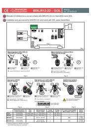
1 Wiring diagram of the right hand side of the control unit<br />
Fig. 7 shows a diagram of the connection terminals for the aerial, various controls and the various power supplies (indicator light, electrolock,<br />
flashing light, courtesy light, photocells, selectors, etc.). . These are the vertical terminals positioned on the right hand side of the control unit and<br />
numbered from 1 to 19.<br />
Terminals<br />
Description<br />
1 - 2 Aerial: aerial cable input 1 sheath, 2 cables. Use a RG58- 50ohm cable<br />
6 Common: for stop, open, close, step and photo inputs.<br />
6 - 7 STOP*: programmable NC input, commands gate stoppage. Can be connected to safety devices such as an emergency stop button.<br />
When the command is released automatic closure never occurs and a new movement command must be given.<br />
Leave jumpered if no device is envisaged<br />
6 - 8 OPEN: NO input, commands gate opening.<br />
6 - 9 CLOSE: NO input, commands gate closure.<br />
6 -10 STEP: NO input, commands gate movement according to the following cycles:<br />
SEMI-AUTOMATIC MODE: Open, stop, close, stop.<br />
4-STEP MODE Open, pause, close, pause.<br />
4-STEP with stop : OPEN-STOP-CLOSE-STOP<br />
CONDOMINIUM MODE: Open.<br />
6 -11 PHOTO 1*: programmable NC input for photocells or safety devices. Causes gate stoppage during both opening and closure. Motion<br />
resumesduring opening when the photocell or safety device is disengaged.Leave jumpered if no device is envisaged.<br />
PHOTO: NC input for photocells or safety devices. Does not intervene during gate opening; during closure causes reversal of gate motionuntil open.<br />
6 - 12<br />
Leave jumpered if no device is envisaged.<br />
16 - 13 ELECTROLOCK 12 V ac output for connection of the 12 Vac 15 VA electrolock.<br />
16 - 14<br />
INDICATOR LIGHT: 24Vac 3W max output, for connecting an indicator light that copies the function of the flashing light during movement<br />
and that remains on when the gate is open.<br />
16 - 15 24 V ac OUTPUT : power supply for various devices, 200 mA max.<br />
16 ELECTROLOCK, INDICATOR LIGHT AND 24 V ac OUTPUT COMMON.<br />
17 PHASE 1, CAPACITOR<br />
18 COMMON OPERATOR 2 POWER SUPPLY: 230 Vac 50 Hz output 300 W max.<br />
19 PHASE 2, CAPACITOR<br />
20 FASE 1, CONDENSATORE<br />
21 COMMON OPERATOR 1 POWER SUPPLY: 230 Vac 50 Hz output 300 W max.<br />
22 FASE 2, CONDENSATORE<br />
23 - 25 FLASHING LIGHT: 230 Vdc 25W max output for connecting a SPLENDOR SRL flashing light characterised by three flashing modes:<br />
1) slow during door opening; 2) fast (flashing times halved) during closure. 3) three flashes and a pause to indicate a fault state or travel identification.<br />
24 - 25<br />
COURTESY LIGHT: 230 Vdc 40W max. output for connecting a courtesy light that switches on at the start of each movement (opening<br />
or closure) and is characterised by an adjustable on time.<br />
-<br />
25 FLASHING OR COURTESY LIGHT POWER SUPPLY COMMON.<br />
L 1<br />
L 2<br />
230Vac 50Hz POWER SUPPLY, fusable input L2.