IST311.4858 Rev00-POA1:Layout 1 - Automatizari pentru porti
IST311.4858 Rev00-POA1:Layout 1 - Automatizari pentru porti
IST311.4858 Rev00-POA1:Layout 1 - Automatizari pentru porti

Create successful ePaper yourself
Turn your PDF publications into a flip-book with our unique Google optimized e-Paper software.
<strong>POA1</strong><br />
Control unit<br />
EN - Instructions and warnings for installation and use
ENGLISH<br />
GENERAL SAFETY WARNINGS AND PRECAUTIONS<br />
EN<br />
Summary<br />
Original instructions<br />
GENERAL SAFETY WARNINGS AND PRECAUTIONS . . . . . . . . . 1<br />
1 – PRODUCT DESCRIPTION . . . . . . . . . . . . . . . . . . . . . . . . . . . . . . . . 1<br />
2 – INSTALLATION . . . . . . . . . . . . . . . . . . . . . . . . . . . . . . . . . . . . . . . . . . 1<br />
2.1 - PRELIMINARY CHECKS FOR INSTALLATION . . . . . . . . . . . . . . 2<br />
2.2 - PRODUCT APPLICATION LIMITS . . . . . . . . . . . . . . . . . . . . . . . 2<br />
2.3 - ELECTRICAL CONNECTIONS . . . . . . . . . . . . . . . . . . . . . . . . . . 2<br />
2.3.1 - Notes on connections . . . . . . . . . . . . . . . . . . . . . . . . . . . 2<br />
2.3.2 - Type of ALT input . . . . . . . . . . . . . . . . . . . . . . . . . . . . . . . 3<br />
2.4 - INITIAL START-UP AND ELECTRICAL CONNECTIONS . . 3<br />
2.5 - AUTOMATIC LIMIT SWITCH SEARCH . . . . . . . . . . . . . . . . . . . . 3<br />
3 – TESTING AND COMMISSIONING . . . . . . . . . . . . . . . . . . . . . . . . . . 4<br />
3.1 - TESTING . . . . . . . . . . . . . . . . . . . . . . . . . . . . . . . . . . . . . . . . . . . 4<br />
3.2 - COMMISSIONING . . . . . . . . . . . . . . . . . . . . . . . . . . . . . . . . . . . . 4<br />
4 – DIAGNOSTICS . . . . . . . . . . . . . . . . . . . . . . . . . . . . . . . . . . . . . . . . . . 4<br />
5 – PROGRAMMING . . . . . . . . . . . . . . . . . . . . . . . . . . . . . . . . . . . . . . . . 4<br />
5.1 - PRESET FUNCTIONS . . . . . . . . . . . . . . . . . . . . . . . . . . . . . . . . . 4<br />
5.2 - PROGRAMMABLE FUNCTIONS . . . . . . . . . . . . . . . . . . . . . . . . 4<br />
5.2.1 - Direct programming . . . . . . . . . . . . . . . . . . . . . . . . . . . . 4<br />
5.2.2 - First level programming: first part . . . . . . . . . . . . . . . . . 4<br />
5.2.3 - First level programming: second part . . . . . . . . . . . . . . 5<br />
5.2.4 - Second level functions . . . . . . . . . . . . . . . . . . . . . . . . . . 5<br />
5.3 - PROGRAMMING MODES . . . . . . . . . . . . . . . . . . . . . . . . . . . . . . 5<br />
5.3.1 - First level programming: functions . . . . . . . . . . . . . . . . . 6<br />
5.3.2 - Second level programming: parameters . . . . . . . . . . . . 6<br />
5.3.3 - Deletion of memory . . . . . . . . . . . . . . . . . . . . . . . . . . . . . 6<br />
5.3.4 - Example of first level programming . . . . . . . . . . . . . . . . 7<br />
5.3.5 - Example of second level programming . . . . . . . . . . . . . 7<br />
5.3.6 - Programming diagrame . . . . . . . . . . . . . . . . . . . . . . . . . 8<br />
6 – FURTHER DETAILS: accessories . . . . . . . . . . . . . . . . . . . . . . . . . . 9<br />
6.1 - CONNECTING A RADIO RECEIVER . . . . . . . . . . . . . . . . . . . . . . 9<br />
Safety warnings<br />
• IMPORTANT! – This manual contains important instructions and warnings<br />
for personal safety. Incorrect installation could cause serious physical<br />
injury. Read all parts of the manual carefully before starting work. If in doubt,<br />
interrupt installation and contact the Nice Service Centre for clarifications.<br />
• IMPORTANT! – Important instructions: keep this manual in a safe place<br />
to enable future product maintenance and disposal procedures.<br />
Installation warnings<br />
• Before commencing installation, check that the product is suitable for the<br />
intended kind of use (see paragraph 2.2 “Limits of use” and chapter “Product<br />
technical specifications”). If not suitable, do NOT proceed with installation.<br />
• During installation, handle the product with care, avoiding the risk of crushing,<br />
impact, dropping or contact with any type of liquid. Never place the product<br />
near sources of heat or expose to naked flames. This may damage product<br />
com ponents and cause malfunctions, fire or hazardous situations. If this oc -<br />
curs, suspend installation immediately and contact the Nice Service Centre.<br />
• Never make modifications to any part of the product. Operations other than<br />
as specified can only cause malfunctions. The manufacturer declines all liability<br />
for damage caused by makeshift modifications to the product.<br />
• The product should not be used by children or people with impaired physical,<br />
sensorial or mental capacities or who have not received adequate training in<br />
the safe use of the product.<br />
• On the power line to the system, install a device for disconnection from the<br />
power mains with a gap between contacts that assures complete disconnection<br />
in the conditions of overvoltage category III.<br />
• Connect the control unit to an electric power line equipped with an earthing<br />
system.<br />
• The product’s packaging materials must be disposed of in full compliance<br />
with local regulations.<br />
1<br />
PRODUCT DESCRIPTION<br />
The <strong>POA1</strong> control unit has been designed to control POP 24 V electromechanical<br />
actuators, for automated swing gates or doors. IMPORTANT! – Any uses<br />
other than those specified herein or in environmental conditions other<br />
than as stated in this manual are to be considered improper and are strictly<br />
prohibited!<br />
The <strong>POA1</strong> control unit operates on the basis of a current sensitivity system<br />
which checks the load of the motors connected to it. The system automatically<br />
detects travel stops, memorises the running time of each motor and recognises<br />
obstacles during normal movement. This feature makes installation easier as<br />
there is no need to adjust the working times nor the leaf delay.<br />
The control unit is pre-programmed for the normal functions, while more specific<br />
functions can be chosen following a simple procedure (see chapter 5).<br />
The control unit is designed to be powered by PS124 buffer batteries as emergency<br />
power supply in the event of a mains power failure (for further information<br />
see chapter 6.2). It is also designed to be connected to the “Solemyo” solar<br />
energy system (for further information see chapter 6.3).<br />
6.2 - CONNECTING MODEL PS124 BUFFER BATTERY . . . . . . . . . . 9<br />
6.3 - CONNECTING THE SOLEMYO SYSTEM . . . . . . . . . . . . . . . . . . 9<br />
7 – TROUBLESHOOTING (troubleshooting guide) . . . . . . . . . . . . . . . 9<br />
2<br />
INSTALLATION<br />
8 – PRODUCT MAINTENANCE . . . . . . . . . . . . . . . . . . . . . . . . . . . . . . . 9<br />
DISPOSAL OF THE PRODUCT . . . . . . . . . . . . . . . . . . . . . . . . . . . . 9<br />
TECHNICAL CHARACTERISTICS OF THE PRODUCT . . . . . . . . 10<br />
EC DECLARATION OF CONFORMITY . . . . . . . . . . . . . . . . . . . . . 10<br />
RADIO RECEIVER: SMXI - SMIXS . . . . . . . . . . . . . . . . . . . . . . . . 11<br />
1 - PRODUCT DESCRIPTION . . . . . . . . . . . . . . . . . . . . . . . . . . . . . . 11<br />
2 - AERIAL INSTALLATION . . . . . . . . . . . . . . . . . . . . . . . . . . . . . . . . 11<br />
3 - MEMORISING A REMOTE CONTROL . . . . . . . . . . . . . . . . . . . . 11<br />
4 - DELETING ALL TRANSMITTERS . . . . . . . . . . . . . . . . . . . . . . . . 12<br />
TECHNICAL CHARACTERISTICS OF THE PRODUCT . . . . . . . . . . 12<br />
IMAGES . . . . . . . . . . . . . . . . . . . . . . . . . . . . . . . . . . . . . . . . . . . . . I - VII<br />
In order to explain certain terms and aspects of an automatic 2-leaf swing door<br />
or gate system refer to the typical system shown in fig 1.<br />
Key to fig. 1:<br />
1. Electromechanical actuator PP7024 (with integrated <strong>POA1</strong> control unit)<br />
2. Electromechanical actuator PP7224 (without control unit)<br />
3. Lucy24 flashing light<br />
4. Key-operated selector switch<br />
5. “PHOTO” pair of photocells<br />
6. “FOTO1” pair of photocells<br />
7. “PHOTO2” pair of photocells<br />
In particular, please note that:<br />
• Refer to the product instructions for the characteristics and connection of the<br />
photocells.<br />
• Activation of the “PHOTO” pair of photocells have no effect on the gate during<br />
opening, while they reverse movement during closing.<br />
English – 1
EN<br />
• Activation of the “PHOTO 1” pair of photocells stops both the opening and<br />
closing manoeuvres.<br />
• Activation of the “PHOTO2” pair of photocells (connected to the suitably programmed<br />
AUX input) has no effect during closing while they invert movement<br />
during opening.<br />
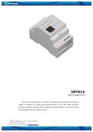
To check the parts of the control unit see fig. 2.<br />
Key to fig. 2:<br />
A. 24V power supply connector<br />
B. M1 motor connector<br />
C. PS124 buffer battery connector / Solemyo solar energy supply<br />
system (for further details see chapter 6.3)<br />
D. 500mA F type services fuse<br />
E. Selector switch for delaying the opening of motor M1 or M2<br />
F. M2 motor terminal<br />
G. Flashing light output terminal<br />
H. Gate open indicator or electric lock output terminal<br />
I. 24Vdc terminals for services and phototest<br />
L. Input terminals<br />
L1…L5. Input and programming LEDs<br />
M. Terminal for radio aerial<br />
N. “SM” radio receiver connector<br />
O. Programming/diagnostics connector<br />
P1, P2, P3. Programming buttons and LEDs<br />
2.1 - Preliminary checks for installation<br />
Before proceeding with installation, check the condition of the product components,<br />
suitability of the selected model and conditions of the intended installation<br />
environment:<br />
• Ensure that all conditions of use remain within the limits of product application<br />
and within the “Product technical specifications”.<br />
• Ensure that the selected installation environment is compatible with the overall<br />
dimensions of the product.<br />
• Ensure that the selected surfaces for product installation are solid and guarantee<br />
a stable fixture.<br />
• Make sure that the fixing zone is not subject to flooding. If necessary, mount<br />
the product raised from the ground.<br />
• Ensure that the space around the product enables easy and safe completion<br />
of manual manoeuvres.<br />
• Make sure that the automation is provided with mechanical stops on both<br />
closing and opening.<br />
2.2 - Product application limits<br />
The product may be used exclusively with POP 24 V gearmotors.<br />
2.3 - Electrical connections<br />
IMPORTANT!<br />
– All electrical connections must be made with the unit disconnected from<br />
the mains power supply and with the buffer battery disconnected, if present<br />
in the automation.<br />
– Connections must be made exclusively by qualified personnel.<br />
– Make sure that all the electric cables used are of a suitable type.<br />
01. Loosen the screws of the cover.<br />
02. Prepare the electrical cable routing holes.<br />
03. Connect the cables as shown in the wiring diagram in fig. 3a - 3b - 3c. To<br />
connect the electric power cable, see fig. 4. Note – To facilitate cable connections,<br />
the terminals can be removed from their seats.<br />
• With the exception of the photocell inputs when the PHOTOTEST function is<br />
activated, if the inputs of the NC (Normally Closed) contacts are not in use<br />
they should be jumped with the “COMMON” terminal. Refer to paragraph<br />
2.4.3 for further information.<br />
• If there is more than one NC contact on the same input, they must be connected<br />
in SERIES.<br />
• If the inputs of the NO (Normally Open) contacts are not used they should be<br />
left free.<br />
• If there is more than one NO contact on the same input, they must be connected<br />
in PARALLEL.<br />
• The contacts must be electromechanical and potential-free. Stage connections,<br />
such as those defined as “PNP”, “NPN”, “Open Collector”, etc. are not<br />
allowed.<br />
• If the leafs overlap, use jumper E (fig. 2) to select which motor starts up first<br />
during opening.<br />
2.3.1 - Notes about connections<br />
Most connections are extremely simple and many of them are direct connections<br />
to a single user point or contact. The following figures show examples of<br />
how to connect external devices:<br />
• Everything in stand by / Phototest connection<br />
The “Everything in stand by” function is active as standard. It is excluded automatically<br />
only when the Phototest function is activated. Note - The “Everything in<br />
stand by” and Phototest functions are alternatives as one excludes the other.<br />
The “Everything in stand by” function allows consumptions to be reduced. Three<br />
types of connections can be obtained:<br />
- with “Everything in stand by” active (energy saving); see electrical diagram in<br />
fig. 3a<br />
- standard connection: without “Everything in stand by” and without “Phototest”;<br />
see electrical diagram in fig. 3b<br />
- without “Everything in stand by” and with “Phototest”; see electrical diagram in<br />
fig. 3c<br />
Key to figs. 2 - 3a - 3b - 3c:<br />
Terminals Function Description Type of cable<br />
L - N - Power supply line Mains power supply 3 x 1,5 mm 2<br />
1÷3 Motor 1 M1 motor connection 3 x 1,5 mm 2<br />
1÷3 Motor 2 M2 motor connection (Note 1) 3 x 1,5 mm 2<br />
4÷5 Flashing light Connection of flashing light 24 V max 25 W 2 x 1 mm 2<br />
6÷7 Open Gate indicator / Connection for Open Gate Indicator 24 V max 5 W or Electric lock 12 V SCA: 2 x 0,5 mm 2<br />
Elect.Lock max 25 VA (“See chapter 5 - Programming”) Electric lock: 2 x 1 mm 2<br />
8 Common 24 V (with Power Supply +24 V for TX photocells with phototest (max. 100 mA); “COMMON” 1 x 0,5 mm 2<br />
Everything in stand by / for all inputs, safety, with “Everything in stand by” function activated (Note 2)<br />
phototest)<br />
9 0 V Power supply 0 V for services 1 x 0,5 mm 2<br />
10 24 V Power input for services, without “Everything in stand by” (24 V max 200 mA) 1 x 0,5 mm 2<br />
11 Common 24 V Common for all inputs (+24 V ) without “Everything in stand by” 1 x 0,5 mm 2<br />
12 STOP Input with STOP function (emergency, safety shutdown) (Note 3) 1 x 0,5 mm 2<br />
13 PHOTO NC Input for safety devices (photocells, sensitive edges) 1 x 0,5 mm 2<br />
14 PHOTO 1 NC Input for safety devices (photocells, sensitive edges) 1 x 0,5 mm 2<br />
15 STEP BY STEP Input for cyclical functioning (OPEN-STOP-CLOSE-STOP) 1 x 0,5 mm 2<br />
16 AUX Auxiliary input (Note 4) 1 x 0,5 mm 2<br />
17÷18 Aerial Connection for the radio receiver aerial screened cable type RG58<br />
Note 1 – This is not used for single leaf gates (the control unit automatically recognises if only one motor has been installed).<br />
Note 2 – The “Everything in stand by” function serves to reduce consumptions. For further details on the electrical connections refer to paragraph 2.4.1 “Everything<br />
in stand by/Phototest connection” and for programming refer to chapter 5.2.3 “Everything in stand by/Phototest function”.<br />
Note 3 – The STOP input can be used for “NC” or constant resistance 8.2 kΩ contacts (please refer to the “Programming” chapter)<br />
Note 4 – The AUX factory auxiliary input is programmed with the “Partial open type 1” function but can be programmed with any of the following functions:<br />
Function Input type Description<br />
PARTIAL OPEN TYPE 1 NO Fully opens the upper leaf<br />
PARTIAL OPEN TYPE 2 NO Opens the two leaf half way<br />
OPEN NO Only carries out the opening manoeuvre<br />
CLOSE NO Only carries out the closing manoeuvre<br />
PHOTO 2 NC PHOTO 2 function<br />
DISABLED — No function<br />
2 – English
When the “Everything in stand by” function is active, 1 minute after the end of a<br />
manoeuvre the control unit goes into “Everything in stand by”, turning off the Inputs<br />
and Outputs to reduce consumptions. The status is indicated by the “OK” LED<br />
which begins to flash more slowly. WARNING – If the control unit is powered from<br />
a photovoltaic panel (“Solemyo” system) or a buffer battery, the “Everything in<br />
stand by” function must be activated as shown in the electrical diagram in fig. 3a.<br />
When the “Everything in stand by” function is not required, the “Phototest” function<br />
may be activated. This verifies at the beginning of a manoeuvre that the connected<br />
photocells operate correctly. To use this function, first connect the photocells<br />
appropriately (see electrical diagram in fig. 3c) and then activate the function.<br />
Note – When the phototest is activated, the inputs subjected to the test<br />
procedure are PHOTO, PHOTO1 and PHOTO2. If one of these inputs is not used<br />
it must be connected to terminal no. 8.<br />
• Key switch connection<br />
Example 1 (fig. 5a): How to connect the switch in order to perform the STEP-<br />
BY-STEP and STOP functions<br />
Example 2 (fig. 5b): How to connect the switch in order to perform the STEP-<br />
BY-STEP and one of the auxiliary input functions (PARTIAL OPENING, OPEN<br />
ONLY, CLOSE ONLY …)<br />
Note – For electrical connections with the “Everything in stand by” function<br />
active, see “Everything in stand by/Phototest function” in this paragraph 2.4.1.<br />
• Connection for Gate Open Indicator / Electric lock (fig. 6)<br />
If the gate open indicator has been programmed, the output can be used as an<br />
open gate indicator light. The light, flashes slowly during opening and quickly<br />
during closing; If it is on but does not flash, this indicates that the gate is open.<br />
If the light is off, the gate is closed. Se the output has been programmed as an<br />
electric lock, it is activated for 3 seconds each time opening begins.<br />
2.3.2 - STOP type input<br />
The <strong>POA1</strong> control unit can be programmed for two types of STOP input:<br />
- NC type STOP for connecting up to NC type contacts.<br />
- Constant resistance STOP. It enables the user to connect up to the control<br />
unit of devices with 8.2kΩ constant resistance (e.g. sensitive edges). The<br />
input measures the value of the resistance and disables the manoeuvre when<br />
the resistance is outside the nominal value. Devices with normally open “NO”<br />
or normally closed “NC” contacts, or multiple devices, even of different types,<br />
can be connected to the constant resistance STOP input, provided that<br />
appropriate adjustments are made; see Table 1.<br />
WARNING! – If the constant resistance STOP input is used to connect<br />
devices with safety functions, only the devices with 8.2 KΩ constant will<br />
resistance output guarantee the fail-safe category 3.<br />
second device type:<br />
TABLE 1<br />
1st device type:<br />
NO NC 8,2 KΩ<br />
In parallel (note 1) (note 2) In parallel<br />
NC (note 2) In series (note 3) In series<br />
8,2 KΩ In parallel In series (note 4)<br />
Notes to Table 1:<br />
Note 1 – Any number of NO devices can be connected to each other in parallel,<br />
with an 8.2 KΩ termination resistance (fig. 7a). For electrical connections<br />
with the “Everything in stand by” function active, see “Everything in stand<br />
by/Phototest function” in this paragraph 2.4.1.<br />
Note 2 – The NO and NC combination can be obtained by placing the two contacts<br />
in parallel, and placing an 8.2 KΩ resistance in series with the NC contact.<br />
It is, therefore, possible to combine 3 devices: NO, NC and 8.2 KΩ (fig. 7b).<br />
Note 3 – Any number of NC devices can be connected in series to each other<br />
and to an 8.2 KΩ resistance (fig. 7c).<br />
Note 4 – Only one device with an 8.2 KΩ constant resistance output can be<br />
connected; multiple devices must be connected “in cascade” with a single 8.2<br />
KΩ termination resistance (fig. 7d).<br />
2.4 - Initial start-up and electrical connections<br />
IMPORTANT! – Connections must be made exclusively by qualified personnel.<br />
After powering up the control unit, check that all the LEDs flash rapidly for a few<br />
seconds, then perform the following checks:<br />
1. Check that there is a voltage of approximately 30Vdc on terminals 9-10. If<br />
not, unplug the unit immediately and carefully check the connections and<br />
input voltage.<br />
2. After initially flashing rapidly, the P1 LED will indicate the control unit is working<br />
correctly by flashing regularly at 1 second intervals. When there is a variation<br />
in the inputs, the “P1” led will rapidly flash twice to show that the input<br />
has been recognised.<br />
3. If the connections are correct, the LED for the “NC”-type inputs will be on,<br />
while those for the “NO” type inputs must be off. See fig. A and Table 2.<br />
A<br />
TABLE 2<br />
INPUT INPUT TYPE STATUS LED<br />
STOP STOP NC L1 On<br />
CONSTANT RESISTANCE L1 On<br />
STOP 8.2 KΩ<br />
PHOTO NC L2 On<br />
FOTO1 NC L3 On<br />
STEP-BY-STEP NO L4 Off<br />
AUX OPEN PARTIALLY type 1 - NO L5 Off<br />
OPEN PARTIALLY type 2 - NO L5 Off<br />
OPEN ONLY - NO<br />
L5 Off<br />
CLOSE ONLY - NO<br />
L5 Off<br />
FOTO2 - NC<br />
L5 On<br />
4.Check that the relative LEDs switch on and off when the devices connected<br />
to the inputs are operated.<br />
5.Check that by pressing P2 both motors perform a short opening manoeuvre,<br />
and the motor of the upper leaf starts first. Block the manoeuvre by pressing<br />
P2 again. If the motors do not start up for opening, invert the polarities of<br />
the motor cables. If, however, the first one to move is not the upper leaf,<br />
operate jumper E (fig. 2).<br />
2.5 - Automatic search system for the limit switches<br />
On the successful completion of the various controls, start the automatic<br />
search system phase for the limit switches. This work is necessary as the <strong>POA1</strong><br />
control unit must “measure” how long the opening and closing manoeuvres<br />
take This procedure is completely automatic and detects the mechanical opening<br />
and closing stops by measuring the load on the motors.<br />
Warning! – If this procedure has already been carried out, in order to<br />
reactivate it, the user must first delete the memory (see the “Memory de -<br />
letion” chapter). In order to check whether the memory contains any li mit<br />
switch parameters, turn the power supply to the control unit on and then<br />
off again. If all the LEDs flash rapidly for approximately 6 seconds, the<br />
me mory is empty. If, however, they only flash for 3 seconds, the memory<br />
already contains some limit switch parameters.<br />
Before starting limit switch searching, make sure that all the safety devices are<br />
enabled (STOP, PHOTO and PHOTO1). The procedure will be immediately<br />
interrupted if a safety device triggers or a command arrives. Ideally the doors<br />
should be half open, although they can be in any position.<br />
Procedure – Press the P2 button (fig. 2) to start begin searching which<br />
includes:<br />
- Both motors open briefly.<br />
- Motor closes the lower leaf until it reaches the mechanical closing stop.<br />
- The upper leaf motor closes until it reaches the mechanical closing stop.<br />
- The motor of the upper leaf begins to open.<br />
- After the programmed delay, opening of the lower leaf begins. If the delay is<br />
in sufficient, block the search by pressing P1 (fig. 2), then modify the time (see<br />
chapter 5).<br />
- The control unit measures the movement required for the motors to reach the<br />
opening mechanical stops.<br />
- Complete closing manoeuvre. The motors can start at different times, the aim<br />
is to prevent the leafs from shearing by maintaining a suitable delay.<br />
- End of the procedure with memorisation of all measurements.<br />
All these phases must take place one after the other without any interference<br />
from the operator. If the procedure does not continue correctly, it must be interrup<br />
ted with the P1 button. Repeat the procedure, modifying some parameters if<br />
necessary, for example the current sensitivity cut-in thresholds (see chapter 5).<br />
EN<br />
English – 3
EN<br />
3<br />
TESTING AND COMMISSIONING<br />
4<br />
DIAGNOSTICS<br />
These are the most important phases of automation set-up for ensuring maximum<br />
system safety. The test can also be performed as a periodic check of<br />
automation devices. Testing and commissioning of the automation must be<br />
performed by skilled and qualified personnel, who are responsible for the tests<br />
required to verify the solutions adopted according to the risks present, and for<br />
ensuring observance of all legal provisions, standards and regulations, and in<br />
particular all requirements of the standard EN 12445, which establishes the test<br />
methods for checking automations for doors and gates.<br />
The additional or optional devices must undergo a specific test for functionality<br />
and correct interaction with <strong>POA1</strong>. Refer to the instruction manuals of the individual<br />
devices.<br />
3.1 - Testing<br />
The testing sequence refers to the control unit programmed with the preset<br />
functions. See paragraph 5.1:<br />
• Make sure that the activation of the STEP-BY-STEP input generates the following<br />
sequence of movements: “Open, Stop, Close, Stop”.<br />
• Make sure that the activation of the AUX input (Type 1 partial opening function)<br />
manages the “Open, Stop, Close, Stop” sequence of the motor of the upper<br />
leaf only, while the motor of the lower leaf remains in the closed position.<br />
• Perform an opening manoeuvre and check that:<br />
- the gate continues the opening manoeuvre when PHOTO is engaged<br />
- the opening manoeuvre stops when PHOTO1 is engaged and only continues<br />
when PHOTO1 is disengaged<br />
- The manoeuvre stops when PHOTO2 (if installed) is engaged and the closing<br />
manoeuvre starts<br />
• Make sure that the motor switches off when the door reaches the mechanical<br />
stop.<br />
• Perform an opening manoeuvre and check that:<br />
- The manoeuvre stops when PHOTO is engaged and the opening manoeuvre<br />
starts<br />
- The manoeuvre stops when PHOTO1 is engaged and the opening manoeuvre<br />
starts again when PHOTO1 is disengaged<br />
- the gate continues the closing manoeuvre when PHOTO 2 is engaged<br />
• Check that the stopping devices connected to the STOP input immediately<br />
stop all movement.<br />
• Check that the level of the obstacle detection system is suitable for the application:<br />
- During both the opening and the closing manoeuvres, prevent the leaf from<br />
moving by placing an obstacle and check that the manoeuvre inverts before<br />
exceeding the force set down by law<br />
• Other checks may be required depending on which devices are connected to<br />
the inputs.<br />
Warning – If an obstacle is detected as moving in the same direction for 2<br />
consecutive manoeuvres in the same direction, the control unit partially<br />
inverts both motors for just 1 second. At the following command, the leafs<br />
begin the opening manoeuvre and the first current sensitivity cut-in for<br />
each motor is considered as a mechanical stop during the opening cycle.<br />
The same happens when the mains power supply is switched on: the first<br />
command is always an opening manoeuvre and the first obstacle is<br />
always considered as a mechanical stop during the opening cycle.<br />
3.2 - Commissioning<br />
Commissioning can only be performed after positive results of all test<br />
phases.<br />
1 Prepare the automation technical documentation, which must contain the<br />
following documents: overall drawing of the automation, electrical wiring<br />
diagram, risk assessment and relative solutions adopted (refer to the relevant<br />
forms on our website www.niceforyou.com), manufacturer’s declaration<br />
of conformity for all devices used and installer’s declaration of conformity.<br />
2 Affix a dataplate on the gate, specifying at least the following data: type of<br />
automation, name and address of manufacturer (responsible for commissioning),<br />
serial number, year of construction and CE mark.<br />
3 Before commissioning the automation, ensure that the owner is adequately<br />
informed of all associated risks and hazards.<br />
4 – English<br />
The diagnostics LED P2 (fig. 2) indicates any problems or malfunctions re -<br />
vealed by the control unit during the manoeuvre.<br />
A sequence with a certain number of flashes indicates the type of problem and<br />
remains active until the following manoeuvre begins. The table below summarises<br />
this information:<br />
Number<br />
Type of malfunction<br />
Led P2 flashes<br />
1 M1 current sensitivity device triggering<br />
2 M2 current sensitivity device triggering<br />
3 STOP input cut-in during the manoeuvre<br />
4 Phototest error<br />
5 Output overcurrent gate open indicator or electric lock<br />
5<br />
PROGRAMMING<br />
The <strong>POA1</strong> control unit features some programmable functions. These functions<br />
are pre-set in a typical configuration which satisfies most automatic systems.<br />
These functions can be changed at any time, both before and after searching<br />
automatically for limit switches, by carrying out the relevant programming procedure;<br />
see paragraph 5.3.<br />
5.1 - Preset functions<br />
• Motor movement:<br />
fast<br />
• Automatic closing:<br />
enabled<br />
• Condominium function:<br />
disabled<br />
• Pre-flashing<br />
disabled<br />
• Close after photo:<br />
disabled<br />
• Opening delay: level 2 (10%)<br />
• Everything in stand by / Phototest: Everything in stand by<br />
• Gate open indicator/Electric Lock: Gate open indicator<br />
• STOP input:<br />
NC type<br />
• Heavy gates:<br />
disabled<br />
• Pro<strong>porti</strong>onal gate open indicator: disabled<br />
• Pause time:<br />
20 seconds<br />
• Auxiliary input:<br />
type 1 partial opening (only the<br />
upper leaf motor is activated)<br />
• Current sensitivity: Level 2<br />
5.2 - Programmable functions<br />
To ensure the system is best suited to the user’s requirements, and safe in the<br />
various different conditions of use, the <strong>POA1</strong> control unit offers the possibility to<br />
programme several functions or parameters, as well as the function of a number<br />
of inputs and outputs.<br />
5.2.1 - Direct programming<br />
• Slow/rapid movement: The user can choose the speed of movement of the<br />
gate, at any time (with the motor arrested) simply by operating the P3 key (fig.<br />
2) at any time the control unit is not being programmed. If LED L3 is off, this<br />
shows that the slow movement has been set, if on the fast one has.<br />
5.2.2 - Level one programming: part one<br />
• Automatic closing: This function features an automatic closing cycle after<br />
the programmed pause time; the pause time is factory set to 20 seconds but<br />
it can be modified to 5, 10, 20, 40 or 80 seconds.<br />
If the function is not activated, the system will run “semi-automatically”.<br />
• “Condominium” function: This function is useful when the automatic system<br />
is radio-commanded by many different people. If this function is active,<br />
each command received triggers an opening manoeuvre that cannot be interrupted<br />
by further commands. If the function has been deactivated, a command<br />
causes: OPEN-STOP-CLOSE-STOP.<br />
• Pre-flashing: This function activates the flashing light before the manoeuvre<br />
begins for a time that can be programmed to 3 seconds.<br />
If the function is disabled, the light will start flashing when the manoeuvre<br />
starts.<br />
• Close after photo: During the automatic closing cycle, this function reduces<br />
the pause time to 4 seconds after the PHOTO photocell has disengaged, i.e.<br />
the gate closes 4 seconds after the user has passed through it. If the function<br />
is disabled, the whole programmed pause time will pass.<br />
• Opening delay: During opening, this function causes a delay in the activation
of the lower leaf motor compared with the upper one This is necessary in<br />
order to prevent the leafs from getting stuck. There is always a standard delay<br />
during closing, calculated automatically by the control unit in order to ensure<br />
the same delay as the one programmed for opening.<br />
5.2.3 - Level one programming: part two<br />
• Stand By / Phototest function: The control unit has the “Everything in stand<br />
by” function preset. If this function is active, 1 minute after the end of a<br />
manoeuvre the control unit turns off the “Everything in stand by” output (terminal<br />
no. 8) and all the Inputs and other Outputs to reduce consumptions<br />
(see electrical diagram in fig. 3a). This function is obligatory if the control unit<br />
is powered exclusively with Solemyo photovoltaic panels. It is also recommended<br />
if the control panel is powered from the electric mains and if you<br />
wish to extend emergency operation with the buffer battery PS124. As an<br />
alternative to the “Everything in stand by” function, the “Phototest” function<br />
may be activated. This verifies at the beginning of a manoeuvre that the connected<br />
photocells operate correctly. To use this function, connect the photocells<br />
correctly (see electrical diagram in fig. 3c) and then activate the function.<br />
• Open gate indicator light / electric lock: If the function is activated, terminals<br />
6-7 can be used to connect up the electric lock. If the function is deactivated,<br />
terminals 6-7 can be used to connect up a 24V gate open indicator.<br />
• NC Type or Constant Resistance STOP Input: If the function is activated,<br />
the STOP input is set to “8.2KΩ Constant Resistance”. In this case, there<br />
must be a 8.2KΩ +/-25% resistance between the common and the input to<br />
enable the operation. If the function is not set, the configuration of the STOP<br />
input will enable it to function with NC type contacts.<br />
• Light/heavy gates: If the function is activated, the control unit enables the<br />
user to manage heavy gates, setting the acceleration ramps and slowdown<br />
speeds during closing differently. If the function is deactivated, the control unit<br />
will be set to manage light gates.<br />
• Pro<strong>porti</strong>onal gate open indicator: If the function is activated, the gate open<br />
in dicator output will be set with the pro<strong>porti</strong>onal flashing light. This means that<br />
during opening, the flashing becomes more intense as the leafs come nearer<br />
to the opening stops; vice-versa, for closing, the flashing becomes less<br />
intense as the leafs come nearer to the closing stops. If the function is deactivated,<br />
the light will flash slowly during opening and rapidly during closing.<br />
5.2.4 - Level two functions<br />
• Pause time: The pause time, namely the time which lapses between opening<br />
and closing during automatic functioning, can be programmed to 5, 10, 20,<br />
40, and 80 seconds.<br />
• Auxiliary input AUX: The control unit offers an auxiliary input which can be<br />
set to carry out one of the following 6 functions:<br />
- Partial opening type 1: this carries out the same function as the STEP-BY-<br />
STEP input. It causes only the upper leaf to open. It only works if the gate is<br />
closed completely, otherwise the command is interpreted as if it were a<br />
STEP-BY-STEP comman.<br />
- Partial opening type 2: this carries out the same function as the STEP-BY-<br />
STEP input. It causes the two leafs to open for half the time it would take<br />
them to open completely. It only works if the gate is closed completely, otherwise<br />
the command is interpreted as if it were a STEP-BY-STEP command.<br />
- Open only: this input only causes opening in the Open-Stop-Open-Stop<br />
sequence.<br />
- Close only: this input only causes closing in the Open-Stop-Open-Stop<br />
sequence.<br />
- Photo 2: this carries out the function of the “PHOTO 2” safety device.<br />
- Disabled: the input will not carry out any function<br />
• Discharge time: At the end of the Closing manoeuvre, after the leafs have<br />
reached the totally closed position, the motor continues to “push” the leaf for<br />
a brief interval, to ensure perfect closure. Immediately afterwards, this function<br />
activates a very brief inversion of movement to reduce excessive pressure<br />
exerted by the motor on the leafs.<br />
• Current sensitivity: The control unit is equipped with a system which measures<br />
the current absorbed by the two motors used to detect the mechanical<br />
stops and any obstacles when the gate is moving. Since the current ab -<br />
sorbed depends on a number of conditions, including the weight of the gate,<br />
friction, wind and variations in voltage, the cut-in threshold can be changed.<br />
There are 6 levels: 1 is the most sensitive (minimum force), 6 is the least sensitive<br />
(maximum force).<br />
By increasing the amperometric sensitivity level the deceleration speed<br />
increases during the closing phase of the manoeuvre.<br />
WARNING! – If the “current sensitivity” function (together with other<br />
vital features) is adjusted correctly, the system will comply with European<br />
standards, EN 12453 and EN 12445, which require techniques or<br />
devices to be used to limit force and danger during the functioning of<br />
automatic gates and doors are moved.<br />
• Leaf delay: The delay in starting up the motor of the lower leaf can be programmed<br />
to 5, 10, 20, 30 or 40% of the working time.<br />
The P1, P2 and P3 buttons are used for all the programming phases, while the<br />
5 LEDs (L1, L2…L5) indicate the selected parameter.<br />
There are two different programming levels:<br />
• At level 1, the functions can be enabled or disabled. Each Led (L1, L2…L5)<br />
corresponds to a function: if the Led is on, the function is active; if it is off, it is<br />
deactivated.<br />
Level one consists in 2 parts which can be selected using the P3 button. The<br />
cor responding LED P3 indicates which of the 2 parts has been selected.<br />
Level one (P1 Led lit): part one ( P3 Led off)<br />
L1 Led L2 Led L3 Led L4 Led L5 Led<br />
Closing Function Pre-flash Close after Delay in<br />
Automatic Condominium photo opening<br />
Level one (P1 Led lit): part two (P3 Led lit)<br />
L1 Led L2 Led L3 Led L4 Led L5 Led<br />
Everything in Electric lock Resistance Heavy gates Gate open<br />
stand by / stop pro<strong>porti</strong>onal<br />
Phototest<br />
• It is possible to pass to the second level from level one of part one. At this<br />
second level the user can choose the parameter relating to the function. A<br />
different value corresponds to each LED which must be associated to the<br />
parameter.<br />
Level one (P1 Led lit): part one (led P3 off)<br />
L1 Led L2 Led L3 Led L4 Led L5 Led<br />
Closing Function Pre-flashing Close after Delay in<br />
automatic condominium photo opening<br />
Level two:<br />
Parameter: Parameter: Parameter: Parameter: Parameter:<br />
Time AUX input Time Current Leaf delay<br />
pause discharge sensitivity<br />
L1: 5s L1: Open L1: no L1: Level 1 L1: 5%s<br />
partial TYPE 1 discharge (more sensitive)<br />
L2: 10s L2: Open L2: 0.3s L2: Level 2 L2: 10%<br />
partial TYPE 2<br />
L3: 20s L3: Open Only L3: 0.7s L3: Level 3 L3: 20%<br />
L4: 40s L4: Close Only L4: 1.3s L4: Level 4 L4: 30%<br />
L5: 80s L5: Photo 2 L5: 2s L5: Level 5 L5: 40%<br />
(less sensitive)<br />
All LEDs off:<br />
All LEDs off:<br />
input Level 6<br />
not used<br />
(max current<br />
sensitività )<br />
Level one (P1 Led lit): part two (P3 Led lit)<br />
L1 Led L2 Led L3 Led L4 Led L5 Led<br />
Everything in Electric lock Resistance Heavy gates Gate open<br />
stand by / stop pro<strong>porti</strong>onal<br />
Phototest<br />
EN<br />
5.3 - Programming<br />
All the functions described in paragraph 5.2 “Programmable functions” chapter<br />
can be selected by means of a programming phase which terminates by memorising<br />
the choices made. The control unit therefore has a memory which stores<br />
the functions and parameters relative to the automation process.<br />
English – 5
EN<br />
5.3.1 - Level one programming: functions<br />
At level 1, the functions can be enabled or disabled. At level one, LED P1 is<br />
always on; if LEDs L1, L2…L5 are on, the functions are activated; if the LEDs<br />
are off, the functions are deactivated. A flashing LED indicates which function<br />
has been selected, short flashes indicate the function has been deactivated;<br />
long flashes indicate the function has been activated. Press P3 to pass from<br />
part one programming to part two programming, and vice-versa.<br />
TABLE A1 - Entering level one programming<br />
01. Press and hold down buttons P1 and P2 for at least 3 seconds<br />
The programming mode has been entered if all the Leds start flashing quickly<br />
P1<br />
P2<br />
TABLE A2 - Activating or deactivating a function<br />
01. Press P1 repeatedly until the flashing Led reaches the function required<br />
P1<br />
02. Press P1 repeatedly until the flashing Led reaches the function required<br />
P2<br />
TABLE A3 - To pass from part one to part two of level one (and vice-versa)<br />
01. Press P3. button<br />
P3<br />
TABLE A4 - To exit level one and save the modifications<br />
01. Press P1 and then immediately P2, holding them both down for at least 3 seconds<br />
P1<br />
P2<br />
3 s<br />
TABLE A5 - Exiting level one and delete the modifications<br />
01. Either press P1 for at least 3 seconds, or wait for 1 minute, or disconnect the power supply<br />
3s P1 or 60s<br />
or<br />
5.3.2 - Level two programming: parameters<br />
The function parameter can be chosen at level two. Level two can only be<br />
reached from level one. At level 2 the P1 Led flashes quickly while the 5 Leds<br />
(L1, L2…L5) indicate the selected parameter.<br />
TABLE B1 - Entering level two programming<br />
01. Enter level one programming by pressing P1 and P2 for at least 3 seconds<br />
P1<br />
P2<br />
3 s<br />
02. Select the function by pressing P1 until the flashing Led reaches the point required<br />
P1<br />
03. Enter level two by pressing the P2 button for at least 3 seconds<br />
P2<br />
3 s<br />
TABLE B2 - Selecting the parameter<br />
01. Press P2 repeatedly until the Led reaches the desired parameter<br />
P2<br />
TABLE B3 - Returning to level one<br />
01. Press P1<br />
P1<br />
TABLE B4 - Exiting level one and saving modifications<br />
01. Press P1 and then immediately P2, holding them both down for at least 3 seconds<br />
P1<br />
P2<br />
TABLE B5 - Exiting level one and cancelling modifications<br />
01. Either press P1 for at least 3 seconds, or wait for 1 minute, or disconnect the power supply<br />
3s P1 or 60s<br />
or<br />
5.3.3 - Memory deletion<br />
Each new programme replaces the previous settings. It is usually unnecessary<br />
to “delete all” the parameters”. If required, the memory can be totally deleted by<br />
6 – English<br />
performing this simple operation: WARNING – As all the functions return to<br />
their pre-set values after the memory is deleted, a new search for the limit<br />
switches must be carried out.
TABLE C1 - Delete memory<br />
EN<br />
01. Switch the power supply to the control box off, and wait until all the LEDs have gone off (remove fuse F1 if necessary)<br />
02. Press P1 and P2 on the board down and keep them pressed down<br />
P1<br />
P2<br />
03. Switch the power supply on again<br />
04. Wait at least 3 seconds before releasing the two keys<br />
P1<br />
P2<br />
3s<br />
If the memory was deleted correctly, all the Leds will switch off for 1 second<br />
5.3.4 - Example of level one programming<br />
The following examples show how to activate or deactivate a level one function,<br />
the “Condominium” function, for example, and prepare the “Gate Open Indicator”<br />
output in order to activate the electric lock.<br />
Example of level one programming:<br />
activate the “Condominium” function and “Electric lock” output<br />
01. Access the level one programming mode by pressing P1 and P2, and keeping them pressed down for at least 3 seconds<br />
P1<br />
P2<br />
3s<br />
02. Press P1 once to move the flashing Led to the Led 2 (the flashes will be short)<br />
03. Activate the “Condominium” function by pressing P2 (the flashes will be longer)<br />
04. Press P3 once in order to activate part two (the P3 LED will switch on)<br />
05. Press P1 once to move the flashing Led to the Led 2 (the flashes will be short)<br />
06. Activate the “Electric lock” output by pressing P2 (the flashes will be longer)<br />
P1 x1<br />
P1<br />
2<br />
P2<br />
P3<br />
2<br />
P2<br />
07. Exit programming (with memorisation) by pressing P1 and then immediately P2, holding them both down<br />
for at least 3 seconds<br />
P1<br />
P2<br />
3s<br />
5.3.5 - Example of level two programming<br />
This example shows how to modify a level two parameter, for example, how to<br />
modify current sensitivity intil “level 5”.<br />
Example of level two programming: modifying “current sensitivity”<br />
01. Access the level one programming mode by pressing P1 and P2 for at least 3 seconds<br />
P1<br />
P2<br />
3s<br />
02. Press P1 three times to move the flashing Led to the Led 4<br />
P1 x3<br />
4<br />
03. Access level two by pressing P2 for at least 3 seconds<br />
P2<br />
3s<br />
04. Press P2 three times until Led 5 switches on<br />
P2 x3<br />
5<br />
05. Return to level one by pressing P1<br />
P1<br />
06. Exit programming (with memorisation) by pressing P1 and then immediately P2, holding them both down<br />
for at least 3 seconds<br />
P1<br />
P2<br />
3s<br />
English – 7
EN<br />
5.3.6 - Programming diagram<br />
The following figure shows the complete programming diagram of the functions<br />
and relative parameters.<br />
This figure also shows the functions and parameters either as they were initially<br />
or following total memory deletion.<br />
Normal<br />
operation<br />
Led P1 Slow flashing<br />
ALT Photo Photo<br />
1<br />
Step<br />
by<br />
step<br />
AUX<br />
P1<br />
P2<br />
P3<br />
P1+P2<br />
for 3 secs<br />
P1<br />
for 3 secs<br />
(NO SAVE)<br />
P1+P2<br />
for 3 secs<br />
(SAVE)<br />
Level one<br />
Led P1 On permanently<br />
Autom. Cond.<br />
closing<br />
Preflashing<br />
Close<br />
after<br />
Photo<br />
Opening<br />
delay<br />
P1<br />
P2<br />
P3<br />
On<br />
Off<br />
P3<br />
Everything<br />
in<br />
stand<br />
by /<br />
Phototest<br />
Electric<br />
Lock<br />
Resist. Heavy Pro<strong>porti</strong>onal<br />
STOP. gates Gate<br />
Open<br />
P1<br />
P2<br />
P3<br />
On<br />
Off<br />
PAUSE TIME<br />
P2<br />
for 3 secs<br />
P1<br />
5 10 20<br />
seconds<br />
40 80<br />
P1<br />
P2<br />
P3<br />
AUXILIARY INPUT (*)<br />
Level two<br />
Led P1 Rapid flashing type 1<br />
p.o<br />
type 2<br />
p.o<br />
only only Photo 2<br />
opening closing<br />
P1<br />
P2<br />
P3<br />
DISCHARGE<br />
0 0,3 0,7<br />
seconds<br />
1,3 2<br />
P1<br />
P2<br />
P3<br />
CURRENT SENSITIVITY<br />
P1<br />
1 2 3 4 5<br />
Level<br />
P2<br />
P3<br />
All Leds off · max. current sensitivity<br />
OPENING DELAY<br />
P1<br />
(*)<br />
a.p. type 1<br />
a.p. type 2<br />
Only open<br />
type 1 partial open, upper leaf<br />
moves [N.O.]<br />
type 2 partial opening, both<br />
motors move for 1/2 the working<br />
time set [N.O.]<br />
open ➔ stop ➔ open ➔ stop…<br />
[N.O.]<br />
5 10 20<br />
%<br />
30 40<br />
P2<br />
P3<br />
Only closed<br />
Photo 2<br />
close ➔ stop ➔ close ➔ stop…<br />
[N.O.]<br />
used as photo 2 [N.C.]<br />
8 – English
6<br />
FURTHER DETAILS: accessories<br />
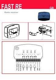
6.1 - Connecting a radio receiver<br />
The control unit has a connector for fitting a 4 channel radio card complete with<br />
SM slot. This remote control device functions by means of transmitters which<br />
act on the inputs as per the following table:<br />
Output Receiver Control unit input<br />
N° 1 Step by step<br />
N° 2 AUX (reset value: Partially Open 1)<br />
N° 3 “Open only”<br />
N° 4 “Close only”<br />
6.2 - Connecting model PS124 buffer battery<br />
PS124 buffer batteries can be used to supply the control unit in case of network<br />
blackouts. To install and connect the battery, proceed as shown in fig. 8.<br />
6.3 - Connecting the Solemyo system<br />
The control unit is designed to be powered with the “Solemyo” photovoltaic<br />
system (photovoltaic panel and 24 V battery). To connect the Solemyo battery<br />
to the control unit, use the socket on the control unit that is normally used for<br />
the buffer battery (see paragraph 6.2).<br />
IMPORTANT!<br />
- When the automation is powered by the “Solemyo” system, it MUST<br />
NOT BE POWERED at the same time from the electrical mains.<br />
- The Solemyo system can be used only if the “Everything in stand by”<br />
function on the con trol unit is ON and the connections are as shown in the<br />
diagram in fig. 3a.<br />
7<br />
TROUBLESHOOTING<br />
(troubleshooting guide)<br />
No LEDs are on:<br />
• Check whether the control unit is powered (measure a voltage of about<br />
30Vdc at terminals 9-10 (or 24 Vdc with battery power).<br />
• Check the 2 fuses, if not even the P1 Led is on or flashing a serious fault has<br />
probably occurred and the control unit must therefore be replaced.<br />
the mechanical stops, therefore). This is considered as an obstacle and<br />
causes an inversion. To find out if the current sensitivity device has triggered,<br />
count how many times the Diagnostics LED flashes: 1 flash indicates that the<br />
current sensitivity device triggered on account of motor 1, 2 flashes indicate<br />
that this was caused by motor 2.<br />
8<br />
PRODUCT MAINTENANCE<br />
As the <strong>POA1</strong> control unit is electronic it requires no particular maintenance.<br />
However, at least every six months the efficiency of the entire system must be<br />
checked according to the information described in chapter 3.<br />
DISPOSAL OF THE PRODUCT<br />
This product is an integral part of the automation, and therefore, they<br />
must be disposed of together.<br />
As for the installation operations, at the end of the life of this product, the dismantling<br />
operations must be performed by qualified personnel.<br />
This product is made from different types of materials: some can be recycled,<br />
others must be disposed of. Please inform yourselves on the recycling or disposal<br />
systems provided for by the laws in force in your area, for this category of<br />
product.<br />
CAUTION! – some parts of the product can contain polluting or dangerous<br />
substances which, if dispersed in the environment, may cause serious harm to<br />
the environment and human health.<br />
As indicated by the symbol at the side, it is forbidden to<br />
throw this product into domestic refuse. Therefore, follow the<br />
“separated collection” instructions for disposal, according to<br />
the methods provided for by local regulations in force, or<br />
redeliver the product to the retailer at the moment of purchase<br />
of a new, equivalent product.<br />
CAUTION! – the regulations in force at local level may envisage heavy sanctions<br />
in case of abusive disposal of this product.<br />
EN<br />
The P1 LED flashes regularly but the input LED’s L1, L2...L5 do not reflect<br />
the state of the respective inputs<br />
• Switch the unit off for the moment in order to exit a possible programming<br />
phase.<br />
• Carefully check the connections on terminals 11 to 16.<br />
LED P1 flashes every 4 seconds<br />
• The control unit is in “Everything in stand by” status.<br />
The “Automatic search” procedure does not start up<br />
• The “Automatic search” procedure only starts if it has never been performed<br />
before or if the memory has been deleted. To check whether the memory is<br />
empty switch off the unit for a moment. When it is switched on again, all the<br />
Leds should flash rapidly for about 6 seconds. If they only flash for 3 seconds,<br />
the memory already contains valid values. If a new “Automatic search”<br />
is required, the memory must be completely deleted.<br />
The “Automatic search” procedure has never been performed but it either<br />
does not start or it behaves incorrectly<br />
• The system and all the safety devices must be operative in order to activate<br />
the “Automatic search” procedure.<br />
• Make sure that no device connected to the inputs cuts in during the “Automatic<br />
search” procedure.<br />
• In order for the “Automatic search” procedure to start correctly, the input<br />
Leds must be on as shown in fig. 9, the P1 Led must flash once a second.<br />
The “Automatic search” procedure was performed correctly but the<br />
manoeuvre does not start<br />
• Check that the safety device (STOP, PHOTO, PHOTO1 and, if installed,<br />
PHOTO2) Leds are on and that the relative command Led (STEP-BY-STEP<br />
or AUX) remains on for the entire duration of the command.<br />
• If the “Phototest” function is activated but the photocells do not function correctly,<br />
the DIAGNOSTICS LED indicates the fault by flashing four times.<br />
The gate inverts the direction while moving<br />
An inversion is caused by:<br />
• The photocells triggering (PHOTO2 during the opening manoeuvre, PHOTO<br />
or PHOTO1 during the closing manoeuvre). In this case, check the photocell<br />
connections and input LEDs.<br />
• The current sensitivity device triggers while the motors are moving (not near<br />
English – 9
EN<br />
TECHNICAL CHARACTERISTICS OF THE PRODUCT<br />
WARNINGS: • All technical characteristics stated refer to an ambient temperature of 20°C (±5°C). • Nice S.p.a reserves the right to modify the product at any<br />
timee, while maintaining the same functionalities and intended use.<br />
Mains power supply <strong>POA1</strong> Control units: 230 V ±10% 50 ÷ 60 Hz<br />
<strong>POA1</strong>/V1 Control units: 120 V ±10% 50 ÷ 60 Hz<br />
Max absorbed power<br />
Emergency power supply<br />
Maximum motor current:<br />
170 VA<br />
for PS124 buffer batteries and for Solemyo solar kit<br />
3A (with a “level 6” current sensitivity cut in)<br />
Service power output 24 V 200 mA maximum current (the voltage can vary from 16 to 33 V )<br />
Phototest Output 24 V 100 mA maximum current (the voltage can vary from 16 to 33 V )<br />
Flashing lamp output for flashing lamp 24 V , maximum power 25 W (the voltage can vary from 16 to 33 V )<br />
Gate open indicator output for indicator lamps at 24 V maximum power 5 W (the voltage can vary from 16 to 33 V )<br />
or electric locks 12 V 25 W<br />
STOP Input for NC contacts or constant resistance 8,2 KΩ +/- 25%<br />
Working time<br />
Pause time<br />
Discharge time<br />
Leaf delay in open cycle<br />
Leaf delay in close cycle<br />
automatic detection<br />
programmable at 5, 10, 20, 40, 80 seconds<br />
programmable to 0, 0.3, 0.7, 1.3, 2 seconds<br />
programmable at 5, 10, 20, 30 and 40 % of working time<br />
automatic detection<br />
2 nd motor output for motor POP (PP7224)<br />
Max. cable length 230 V power supply 30 m<br />
Solemyo solar power kit 3 m<br />
motor<br />
10 m<br />
other inputs/outputs<br />
30 m<br />
flashing light<br />
10 m<br />
SCA<br />
30 m<br />
electric lock<br />
10 m<br />
aerial 20 m (recommended less than 3 m)<br />
Radio receiver<br />
Temperatura di esercizio from - 20 to 50 °C<br />
“SM” type coupling for receivers SMXI, SMXIS, OXI (Mode I and Mode II)<br />
EC DECLARATION OF CONFORMITY<br />
Note - The contents of this declaration correspond to declarations in the last revision of the official document deposited at the registered offices of Nice Spa available before this<br />
manual was printed. The text herein has been re-edited for editorial purposes.<br />
Number: 173/PP7024 Revision: 3<br />
The undersigned, Luigi Paro, in the role of Managing Director, declares under his sole responsibility, that the product:<br />
Manufacturer’s Name: NICE s.p.a.<br />
Address:<br />
Via Pezza Alta 13, Z.I. Rustignè, 31046 Oderzo (TV) Italy<br />
Type:<br />
Electromechanical gearmotor with control unit<br />
Models:<br />
PP7024, PP7024/A<br />
Accessories:<br />
No accessory<br />
Conforms to the requirements of the EC directive:<br />
• 98/37/EC DIRECTIVE 98/37/EC OF THE EUROPEAN PARLIAMENT AND COUNCIL of 22 June 1998 regarding the approximation of member state legislation<br />
related to machinery<br />
As envisaged in the directive 98/37/EC, start-up of the product specified above is not admitted unless the machine, in which the product is incorporated,<br />
has been identified and declared as conforming to directive 98/37/EC.<br />
The product also conforms to the requirements of the following EC directives:<br />
• 2006/95/EEC DIRECTIVE 2006/95/EEC OF THE EUROPEAN PARLIAMENT AND COUNCIL of 12 December 2006 regarding the approximation of member<br />
state legislation related to electrical material destined for use within specific voltage limits<br />
According to the following harmonised standards: EN 60335-1:1994+A11:1995+A1:1996+A12:1996<br />
+A13:1998+A14:1998+A15:2000+A2:2000+A16:2001, EN 50366:2003+A1:2006<br />
• 2004/108/EEC DIRECTIVE 2004/108/EEC OF THE EUROPEAN PARLIAMENT AND COUNCIL of 15 December 2004 regarding the approximation of<br />
member state legislation related to electromagnetic compatibility, repealing directive 89/336/EEC<br />
According to the following harmonised standards: EN 61000-6-2:2005; EN 61000-6-3:2007<br />
The product also complies, within the constraints of applicable parts, with the following standards:<br />
EN 60335-1:2002+A1:2004+A11:2004+A12:2006+ A2:2006, EN 60335-2-103:2003,<br />
EN 13241-1:2003; EN 12453:2002; EN 12445:2002; EN 12978:2003<br />
Oderzo, 27.03.09<br />
Ing. Luigi Paro (Managing Director)<br />
10 – English
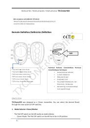
smxi - smixs radio receiver<br />
0682<br />
EN<br />
1<br />
PRODUCT DESCRIPTION<br />
SMXI and SMXIS are 4-channel radio receivers for control units equipped with<br />
SM-type connector. The peculiarity of compatible transmitters is that the identification<br />
code is different for each transmitter. Therefore, in order to allow the<br />
receiver to recognise a determined transmitter, the recognition code must be<br />
memorised. This operation must repeated for each transmitter required to communicate<br />
with the control unit.<br />
Notes:<br />
– Up to a maximum of 256 transmitters can be memorised in the receiver. No<br />
one transmitter can be cancelled; all the codes must be deleted<br />
– For more advanced functions use the appropriate programming unit.<br />
The receiver features 4 outputs, all available on the underlying connector. To<br />
find out which function is performed by each output, see chapter 6.1.<br />
During the transmitter code memorisation phase, one of these two options may<br />
be chosen:<br />
Mode I - Table B1: Each transmitter button activates the corresponding output<br />
in the receiver, that is, button 1 activates output 1, button 2 activates output<br />
2, and so on. In this case there is a single memorisation phase for each transmitter;<br />
during this phase, it doesn’t matter which button is pressed and just one<br />
memory sector is occupied.<br />
Mode II - Table B2: Each transmitter button can be associated with a particular<br />
output in the receiver, e.g., button 1 activates output 2, button 2 activates<br />
output 1, and so on. In this case, the transmitter must be memorised, pressing<br />
the required button, for each output to activate. Naturally, each button can activate<br />
just one output while the same output can be activated by more than one<br />
button. One memory section is occupied for each button.<br />
TABLE B1 - Mode I memorising (All buttons are memorised on the related receiver output)<br />
01. Press and hold down the receiver button for at least 3 seconds<br />
02. Release the button when the Led lights up<br />
03. Push, for at least 2 seconds, any of the buttons of the transmitter to be memorised within 10 seconds<br />
Note – If the procedure was memorised correctly, the Led on the receiver will flash 3 times. If there are other transmitters<br />
to memorise, repeat step 3 within another 10 seconds. The memorisation phase finishes if no new codes are received<br />
for 10 seconds.<br />
RX<br />
RX<br />
TX<br />
3s<br />
2s<br />
x3<br />
TABLE B2 - Mode II memorising (A specific receiver output can be associated to each button)<br />
01. Press and release the receiver button as many times as the number of the desired output (Once for output No. 1,<br />
twice for output No. 2)<br />
RX<br />
02. Check that the LED emits the same number of flashes as the desired output, repeated over 10 seconds in regular<br />
intervals (1 flash if output No. 1, 2 flashes if output No. 2)<br />
03. Within 10 seconds press the desired button on the transmitter to be memorised, holding it down for at least 2 seconds.<br />
Note – If the procedure was memorised correctly, the Led on the receiver will flash 3 times. If there are other transmitters<br />
to memorise, repeat step 3 within another 10 seconds. The memorisation phase finishes if no new codes are received<br />
for 10 seconds.<br />
TX<br />
2s<br />
x3<br />
2<br />
INSTALLING THE AERIAL<br />
The receiver requires an ABF or ABFKIT type aerial to work properly; without an<br />
aerial the range is limited to just a few metres. The aerial must be installed as<br />
high as possible; if there are metal or reinforced concrete structures nearby you<br />
can install the aerial on top. If the cable supplied with the aerial is too short, use<br />
a coaxial cable with 50-Ohm impedance (e.g. low dispersion RG58), the cable<br />
must be no longer than 10 m.<br />
If the aerial is installed in a place that is not connected to earth (masonry structures),<br />
the braid’s terminal can be earthed to provide a larger range of action.<br />
The earth point must, of course, be local and of good quality. If an ABF or<br />
ABFKIT aerial cannot be installed, you can get quite good results using the<br />
length of wire supplied with the receiver as the aerial, laying it flat.<br />
The procedures for memorising the remote controls must be performed within<br />
a certain time limit; please read and understand the whole procedure before<br />
starting.<br />
In order to carry out the following procedure, it is necessary to use the button<br />
located on the box of the radio receiver (reference A, Fig. 1a), and the corresponding<br />
LED (reference B, Fig. 1a) to the left of the button.<br />
1a<br />
3<br />
MEMORISING A REMOTE CONTROL<br />
WARNING – When the memorisation phase is activated, any tran s-<br />
mitter correctly recognised within the reception range of the radio<br />
is memorised. Consider this aspect with care and remove the aerial<br />
if necessary to reduce the capacity of the receiver.<br />
English – 11
EN<br />
Remote memorising<br />
It is possible to enter a new transmitter in the receiver memory without using<br />
the keypad. A previously memorised and operational remote control must be<br />
available. The new transmitter will “inherit” the characteristics of the previously<br />
memorised one. Therefore, if the first transmitter is memorised in mode I, the<br />
new one will also be memorised in mode I and any of the buttons of the transmitter<br />
can be pressed. If the first transmitter is memorised in mode II the new<br />
one will also be memorised in mode II but the button activating the required<br />
output must be pressed on the first transmitter as must the button required to<br />
be memorised on the second. You need to read all the instructions in advance<br />
so you can perform the operations in sequence without interruptions. Now, with<br />
the two remote controls (the NEW one requiring code memorisation and the<br />
OLD one that is already memorised), position yourself within the operating<br />
range of the radio controls (within maximum range) and carry out the instructions<br />
listed in the table.<br />
TABLE B3 - Remote Memorising<br />
01. Press the button on the NEW transmitter for at least 5 seconds and then release<br />
TX<br />
x5s<br />
TX<br />
02. Press the button on the OLD transmitter 3 times slowly<br />
03. Press the button on the NEW transmitter slowly and then release<br />
Note – If there are other transmitters to memorise, repeat the above steps for each new transmitter.<br />
1s<br />
TX TX TX<br />
TX<br />
1s<br />
1s<br />
x1<br />
4<br />
DELETING ALL TRANSMITTERS<br />
All the memorised codes can be deleted as follows:<br />
TABLE B4 - Deleting all transmitters<br />
01. Press the receiver button and hold it down<br />
RX<br />
02. Wait for the Led to light up, then wait for it to switch off and then wait for it to flash 3 times<br />
03. Release the button exactly during the third flash<br />
Note – if the procedure was performed correctly, the Led will flash 5 times after a few moments.<br />
RX<br />
x3<br />
3°<br />
x5<br />
TECHNICAL CHARACTERISTICS OF THE PRODUCT<br />
WARNINGS: • All technical characteristics stated refer to an ambient temperature of 20°C (±5°C). • Nice S.p.a reserves the right to modify the product at any<br />
timee, while maintaining the same functionalities and intended use. • The range of the transmitters and the reception capacity of the receivers may be subject to<br />
interference that may alter their performance. In the event of interference, Nice cannot guarantee the effective capacity of their devices.<br />
Receivers: SMXI SMXIS<br />
Decoding Rolling code 52 bit FLOR Rolling code 64 bit SMILO<br />
Transmitter compatibility FLOR, VERY VR, NICE WAY, ERGO, PLANO, NICE ONE SMILO<br />
Frequency 433.92 MHz 433.92 MHz<br />
Input impedance 52 KΩ 52 KΩ<br />
Outputs 4 (on SM connector) 4 (on SM connector)<br />
Sensitivity better than 0.5 µV better than 0.5 µV<br />
Working temp. from -10°C to + 55° C from -10°C to + 55° C<br />
Transmitters: FLO2R SMILO<br />
Buttons 1, 2 or 4 according to the versions 2 or 4<br />
Power input 12 V Batt. 23 A 12 V Batt. 23 A<br />
Absorption 10 mA 25 mA<br />
Transmission frequency 433.92 MHz 433.92 MHz<br />
Working temp. from -10°C to + 55° C from -10°C to + 55° C<br />
Radiated power estimated approximately 1 mW E.R.P. estimated approximately 1 mW E.R.P.<br />
Range estimated 200 m (outdoors); 35 m (indoors) estimated 200 m (outdoors); 35 m (indoors)<br />
Dimensions / Weight 69 x 39 x 15,5 mm / 31 g. Ø 48 mm x H 14 mm - 14 g<br />
Encoding digital (4.5 x10 15 combinations) digital (18 x 10 15 combinations)<br />
12 – English
IT<br />
EN<br />
EN - Images<br />
NL<br />
FR<br />
ES<br />
IT - Immagini<br />
DE<br />
FR - Images<br />
PL<br />
ES - Imágenes<br />
DE - Bilder<br />
PL - Zdjęcia<br />
NL - Afbeeldingen<br />
I
1<br />
3<br />
4<br />
7<br />
5<br />
5<br />
7<br />
1 2<br />
6 6<br />
2<br />
M1<br />
EN - E = Electric jumper<br />
DE - E = Brücke<br />
L<br />
N<br />
M2<br />
IT - E = Ponticello elettrico<br />
FR - E = Cavalier électrique<br />
ES - E = Conexión eléctrico<br />
PL - E = Mostek elektryczny<br />
NL - E = Elektrische<br />
geleidingsbrug<br />
E F G H I L M<br />
1 2 3<br />
4 5 6 7 8 9 10 111213 14 15 16<br />
L1...L5<br />
D<br />
P1<br />
P2<br />
C<br />
P3<br />
B<br />
A<br />
N<br />
O<br />
II
3a<br />
EN- Connection with “Everything in stand by” active (energy saving)<br />
IT - Collegamento con “Stand by tutto” attivo (risparmio energetico)<br />
TX<br />
RX<br />
FR- Connexion avec « Stand-by total » actif (économie d’énergie)<br />
ES- Conexión con “Stand by todo” activo (ahorro energético)<br />
DE- Anschluss mit aktivem “Stand by - alles” (Energieeinsparung)”<br />
PL - Połączenie z aktywną funkcją “Stand by całego urządzenia”<br />
(oszczędność energii)<br />
PHOTO2<br />
NL- Aansluiting met “Alles stand by” actief (energiebesparing)<br />
3b<br />
EN- Standard connection: without using “Everything in stand<br />
by” or “Phototest”<br />
IT - Collegamento standard: senza utilizzare “Stand by tutto” e<br />
senza “Fototest”<br />
FR- Connexion standard : sans utiliser « Stand-by total » et sans<br />
« Phototest »<br />
ES- Conexión estándar: sin utilizar “Stand by todo” y sin<br />
“Fototest”<br />
DE- Standardanschluss: ohne Nutzung des “Stand by - alles”<br />
und ohne “Fototest”<br />
PL - Połączenie standard: bez wykorzystywania funkcji “Stand<br />
by całego urządzenia” i bez “Fototestu”<br />
NL- Standaard aansluiting: zonder gebruik van “Alles stand by”<br />
en zonder "Fototest”<br />
TX<br />
RX<br />
III
3c<br />
EN- Connection without “Everything in stand by” with<br />
“Phototest”<br />
TX<br />
RX<br />
IT - Collegamento senza “Stand by tutto” con “Fototest”<br />
FR- Connexion sans “Stand by todo” et avec « phototest »<br />
ES- Conexión sin “Stand by todo” con “Fototest”<br />
DE- Ohne “Stand by - alles” und ohne “Phototest”<br />
PL - Połączenie bez funkcji “Stand by całego urządzenia” i z<br />
funkcją “Fototest”<br />
NL- Aansluiting zonder “Alles stand by” met “Fototest”<br />
4<br />
5a<br />
STEP BY STEP<br />
ALT<br />
EN- For the ALT connection with “Everything in stand by” active,<br />
connect terminal no. 8 and not no. 11<br />
IT - Per il collegamento ALT, con “Stand by tutto” attiva, collegare il<br />
morsetto n° 8 e non il n° 11<br />
NC NO C C NO NC<br />
FR- Pour la connexion HALTE, avec « Stand-by total » actif,<br />
connecter la borne n° 8 et pas la n° 11<br />
ES- Para la conexión ALT, con “Stand by todo” activo, conecte el<br />
borne n° 8 y no el n° 11<br />
DE- Für den Anschluss STOPP, bei aktivem “Stand by - alles”, die<br />
Klemme Nr. 8 und nicht 11 anschließen<br />
15<br />
11<br />
11<br />
12<br />
PL - Aby wykonać połączenie STOP z aktywną funkcją ““Stand by<br />
całego urządzenia”należy połączyć zacisk nr 8 a nie nr 11<br />
NL- Voor de aansluiting ALT, met actieve “Alles stand by”, sluit u de<br />
klem 8 aan en niet de klem 11<br />
IV
5b<br />
6<br />
STEP BY STEP<br />
AUX<br />
6<br />
7<br />
NC NO C C NO NC<br />
33 V<br />
max 5 W<br />
12 V~<br />
max 25 VA<br />
15<br />
11<br />
11<br />
16<br />
6<br />
7<br />
7a<br />
7b<br />
7c<br />
11<br />
11<br />
NC<br />
11<br />
NA<br />
NA<br />
NA<br />
8,2KΩ<br />
8,2KΩ<br />
NC<br />
NC<br />
8,2KΩ<br />
12<br />
12<br />
12<br />
EN- With “Everything in stand by” active connect terminal no. 8 and<br />
not no. 11<br />
DE- Bei aktivem “Stand by - alles”, die Klemme Nr. 8 und und nicht 11<br />
anschließen<br />
IT - Con “Stand by tutto” attiva collegare il morsetto n° 8 e non il<br />
n° 11<br />
PL - Z aktywną funkcją “Stand by całego urządzenia” należy<br />
połączyć zacisk nr 8 a nie nr 11<br />
FR- Avec « Stand-by total » actif connecter la borne n° 8 et pas la<br />
n° 11<br />
NL- Met actieve “Alles stand by” sluit u klem 8 aan en niet klem 11<br />
ES- Con “Stand by todo” activo, conecte el borne n° 8 y no el n° 11<br />
7d<br />
11<br />
12<br />
1 2 n 8,2KΩ<br />
Sensitive edge<br />
Sensitive edge<br />
Sensitive edge<br />
IT - Bordo sensibile<br />
FR - Bord sensible<br />
ES - Banda sensible<br />
DE - Schaltleiste<br />
PL - Listwa optyczna<br />
NL - Contactlijst<br />
IT - Bordo sensibile<br />
FR - Bord sensible<br />
ES - Banda sensible<br />
DE - Schaltleiste<br />
PL - Listwa optyczna<br />
NL - Contactlijst<br />
IT - Bordo sensibile<br />
FR - Bord sensible<br />
ES - Banda sensible<br />
DE - Schaltleiste<br />
PL - Listwa optyczna<br />
NL - Contactlijst<br />
V
8<br />
A<br />
B<br />
C<br />
D<br />
9<br />
VI
www.niceforyou.com<br />
Headquarters<br />
Nice SpA<br />
Oderzo TV Italia<br />
Ph. +39.0422.85.38.38<br />
Fax +39.0422.85.35.85<br />
info@niceforyou.com<br />
Nice in Italy<br />
Nice Padova<br />
Padova Italia<br />
Ph. +39.049.87.01.05.1<br />
Fax +39.049.87.07.63.8<br />
infopd@niceforyou.com<br />
Nice Roma<br />
Roma Italia<br />
Ph. +39.06.72.67.17.61<br />
Fax +39.06.72.67.55.20<br />
inforoma@niceforyou.com<br />
Nice Worldwide<br />
Nice France<br />
Buchelay France<br />
Ph. +33.(0)1.30.33.95.95<br />
Fax +33.(0)1.30.33.95.96<br />
info@fr.niceforyou.com<br />
Nice France Sud<br />
Aubagne France<br />
Ph. +33.(0)4.42.62.42.52<br />
Fax. +33.(0)4.42.62.42.50<br />
infomarseille@fr.niceforyou.com<br />
Nice France Rhône Alpes<br />
Decines Charpieu France<br />
Ph. +33.(0)4.78.26.56.53<br />
Fax +33.(0)4.78.26.57.53<br />
infolyon@fr.niceforyou.com<br />
Nice Belgium<br />
Leuven (Heverlee) Belgium<br />
Ph. +32.(0)16.38.69.00<br />
Fax +32.(0)16.38.69.01<br />
info@be.niceforyou.com<br />
Nice Deutschland<br />
Gelnhausen Deutschland<br />
Ph. +49.(0)6051.91.520<br />
Fax +49.(0)6051.91.52.119<br />
info@de.niceforyou.com<br />
Nice España Madrid<br />
Mostoles Madrid España<br />
Ph. +34.(0)9.16.16.33.00<br />
Fax +34.(0)9.16.16.30.10<br />
info@es.niceforyou.com<br />
Nice España Barcelona<br />
Sant Quirze del Valles<br />
Barcelona España<br />
Ph. +34.(0)9.37.84.77.75<br />
Fax +34.(0)9.37.84.77.72<br />
info@es.niceforyou.com<br />
Nice Australia<br />
Wetherill Park Australia<br />
Ph. +61.(0)2.96.04.25.70<br />
Fax +61.(0)2.96.04.25.73<br />
info@au.niceforyou.com<br />
Nice China<br />
Shanghai P. R. China<br />
Ph. +86.21.575.701.46<br />
Fax +86.21.575.701.44<br />
info@niceforyou.com.cn<br />
Nice USA<br />
San Antonio Texas USA<br />
info@us.niceforyou.com<br />
Nice Russia<br />
Odintsovo Moscow Region Russia<br />
Ph. +7.495.739.97.02<br />
Fax +7.495.739.97.02<br />
info@ru.niceforyou.com<br />
Nice South Africa<br />
Johannesburg South Africa<br />
info@co.za.niceforyou.com<br />
Nice Polska<br />
Pruszków Polska<br />
Ph. +48.(022).759.40.00<br />
Fax +48.(022).759.40.22<br />
info@pl.niceforyou.com<br />
Nice Portugal<br />
Mem Martins Portugal<br />
Ph. +351.21.922.82.10<br />
Fax +351.21.922.82.19<br />
info@pt.niceforyou.com<br />
Nice Romania<br />
Cluj Napoca Romania<br />
Ph./Fax +40.(0)264.453.127<br />
info@ro.niceforyou.com<br />
Nice Turkey<br />
Kadikoy Istanbul Turkey<br />
Ph. +90.216.456.34.97<br />
Fax +90.216.455.78.29<br />
info@tr.niceforyou.com<br />
Nice UK<br />
Sutton in Ashfield<br />
United Kingdom<br />
Ph. +44.16.23.55.80.86<br />
Fax +44.16.23.55.05.49<br />
info@uk.niceforyou.com<br />
<strong>IST311.4858</strong> – Rev. 00 – 21-09-2009