IST311.4858 Rev00-POA1:Layout 1 - Automatizari pentru porti
IST311.4858 Rev00-POA1:Layout 1 - Automatizari pentru porti
IST311.4858 Rev00-POA1:Layout 1 - Automatizari pentru porti

You also want an ePaper? Increase the reach of your titles
YUMPU automatically turns print PDFs into web optimized ePapers that Google loves.
When the “Everything in stand by” function is active, 1 minute after the end of a<br />
manoeuvre the control unit goes into “Everything in stand by”, turning off the Inputs<br />
and Outputs to reduce consumptions. The status is indicated by the “OK” LED<br />
which begins to flash more slowly. WARNING – If the control unit is powered from<br />
a photovoltaic panel (“Solemyo” system) or a buffer battery, the “Everything in<br />
stand by” function must be activated as shown in the electrical diagram in fig. 3a.<br />
When the “Everything in stand by” function is not required, the “Phototest” function<br />
may be activated. This verifies at the beginning of a manoeuvre that the connected<br />
photocells operate correctly. To use this function, first connect the photocells<br />
appropriately (see electrical diagram in fig. 3c) and then activate the function.<br />
Note – When the phototest is activated, the inputs subjected to the test<br />
procedure are PHOTO, PHOTO1 and PHOTO2. If one of these inputs is not used<br />
it must be connected to terminal no. 8.<br />
• Key switch connection<br />
Example 1 (fig. 5a): How to connect the switch in order to perform the STEP-<br />
BY-STEP and STOP functions<br />
Example 2 (fig. 5b): How to connect the switch in order to perform the STEP-<br />
BY-STEP and one of the auxiliary input functions (PARTIAL OPENING, OPEN<br />
ONLY, CLOSE ONLY …)<br />
Note – For electrical connections with the “Everything in stand by” function<br />
active, see “Everything in stand by/Phototest function” in this paragraph 2.4.1.<br />
• Connection for Gate Open Indicator / Electric lock (fig. 6)<br />
If the gate open indicator has been programmed, the output can be used as an<br />
open gate indicator light. The light, flashes slowly during opening and quickly<br />
during closing; If it is on but does not flash, this indicates that the gate is open.<br />
If the light is off, the gate is closed. Se the output has been programmed as an<br />
electric lock, it is activated for 3 seconds each time opening begins.<br />
2.3.2 - STOP type input<br />
The <strong>POA1</strong> control unit can be programmed for two types of STOP input:<br />
- NC type STOP for connecting up to NC type contacts.<br />
- Constant resistance STOP. It enables the user to connect up to the control<br />
unit of devices with 8.2kΩ constant resistance (e.g. sensitive edges). The<br />
input measures the value of the resistance and disables the manoeuvre when<br />
the resistance is outside the nominal value. Devices with normally open “NO”<br />
or normally closed “NC” contacts, or multiple devices, even of different types,<br />
can be connected to the constant resistance STOP input, provided that<br />
appropriate adjustments are made; see Table 1.<br />
WARNING! – If the constant resistance STOP input is used to connect<br />
devices with safety functions, only the devices with 8.2 KΩ constant will<br />
resistance output guarantee the fail-safe category 3.<br />
second device type:<br />
TABLE 1<br />
1st device type:<br />
NO NC 8,2 KΩ<br />
In parallel (note 1) (note 2) In parallel<br />
NC (note 2) In series (note 3) In series<br />
8,2 KΩ In parallel In series (note 4)<br />
Notes to Table 1:<br />
Note 1 – Any number of NO devices can be connected to each other in parallel,<br />
with an 8.2 KΩ termination resistance (fig. 7a). For electrical connections<br />
with the “Everything in stand by” function active, see “Everything in stand<br />
by/Phototest function” in this paragraph 2.4.1.<br />
Note 2 – The NO and NC combination can be obtained by placing the two contacts<br />
in parallel, and placing an 8.2 KΩ resistance in series with the NC contact.<br />
It is, therefore, possible to combine 3 devices: NO, NC and 8.2 KΩ (fig. 7b).<br />
Note 3 – Any number of NC devices can be connected in series to each other<br />
and to an 8.2 KΩ resistance (fig. 7c).<br />
Note 4 – Only one device with an 8.2 KΩ constant resistance output can be<br />
connected; multiple devices must be connected “in cascade” with a single 8.2<br />
KΩ termination resistance (fig. 7d).<br />
2.4 - Initial start-up and electrical connections<br />
IMPORTANT! – Connections must be made exclusively by qualified personnel.<br />
After powering up the control unit, check that all the LEDs flash rapidly for a few<br />
seconds, then perform the following checks:<br />
1. Check that there is a voltage of approximately 30Vdc on terminals 9-10. If<br />
not, unplug the unit immediately and carefully check the connections and<br />
input voltage.<br />
2. After initially flashing rapidly, the P1 LED will indicate the control unit is working<br />
correctly by flashing regularly at 1 second intervals. When there is a variation<br />
in the inputs, the “P1” led will rapidly flash twice to show that the input<br />
has been recognised.<br />
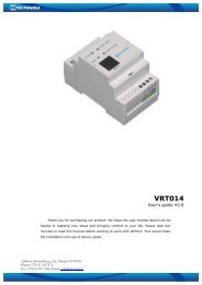
3. If the connections are correct, the LED for the “NC”-type inputs will be on,<br />
while those for the “NO” type inputs must be off. See fig. A and Table 2.<br />
A<br />
TABLE 2<br />
INPUT INPUT TYPE STATUS LED<br />
STOP STOP NC L1 On<br />
CONSTANT RESISTANCE L1 On<br />
STOP 8.2 KΩ<br />
PHOTO NC L2 On<br />
FOTO1 NC L3 On<br />
STEP-BY-STEP NO L4 Off<br />
AUX OPEN PARTIALLY type 1 - NO L5 Off<br />
OPEN PARTIALLY type 2 - NO L5 Off<br />
OPEN ONLY - NO<br />
L5 Off<br />
CLOSE ONLY - NO<br />
L5 Off<br />
FOTO2 - NC<br />
L5 On<br />
4.Check that the relative LEDs switch on and off when the devices connected<br />
to the inputs are operated.<br />
5.Check that by pressing P2 both motors perform a short opening manoeuvre,<br />
and the motor of the upper leaf starts first. Block the manoeuvre by pressing<br />
P2 again. If the motors do not start up for opening, invert the polarities of<br />
the motor cables. If, however, the first one to move is not the upper leaf,<br />
operate jumper E (fig. 2).<br />
2.5 - Automatic search system for the limit switches<br />
On the successful completion of the various controls, start the automatic<br />
search system phase for the limit switches. This work is necessary as the <strong>POA1</strong><br />
control unit must “measure” how long the opening and closing manoeuvres<br />
take This procedure is completely automatic and detects the mechanical opening<br />
and closing stops by measuring the load on the motors.<br />
Warning! – If this procedure has already been carried out, in order to<br />
reactivate it, the user must first delete the memory (see the “Memory de -<br />
letion” chapter). In order to check whether the memory contains any li mit<br />
switch parameters, turn the power supply to the control unit on and then<br />
off again. If all the LEDs flash rapidly for approximately 6 seconds, the<br />
me mory is empty. If, however, they only flash for 3 seconds, the memory<br />
already contains some limit switch parameters.<br />
Before starting limit switch searching, make sure that all the safety devices are<br />
enabled (STOP, PHOTO and PHOTO1). The procedure will be immediately<br />
interrupted if a safety device triggers or a command arrives. Ideally the doors<br />
should be half open, although they can be in any position.<br />
Procedure – Press the P2 button (fig. 2) to start begin searching which<br />
includes:<br />
- Both motors open briefly.<br />
- Motor closes the lower leaf until it reaches the mechanical closing stop.<br />
- The upper leaf motor closes until it reaches the mechanical closing stop.<br />
- The motor of the upper leaf begins to open.<br />
- After the programmed delay, opening of the lower leaf begins. If the delay is<br />
in sufficient, block the search by pressing P1 (fig. 2), then modify the time (see<br />
chapter 5).<br />
- The control unit measures the movement required for the motors to reach the<br />
opening mechanical stops.<br />
- Complete closing manoeuvre. The motors can start at different times, the aim<br />
is to prevent the leafs from shearing by maintaining a suitable delay.<br />
- End of the procedure with memorisation of all measurements.<br />
All these phases must take place one after the other without any interference<br />
from the operator. If the procedure does not continue correctly, it must be interrup<br />
ted with the P1 button. Repeat the procedure, modifying some parameters if<br />
necessary, for example the current sensitivity cut-in thresholds (see chapter 5).<br />
EN<br />
English – 3