torque limiters - safety couplings - Arten Freios e Embreagens ...
torque limiters - safety couplings - Arten Freios e Embreagens ...
torque limiters - safety couplings - Arten Freios e Embreagens ...

Create successful ePaper yourself
Turn your PDF publications into a flip-book with our unique Google optimized e-Paper software.
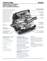
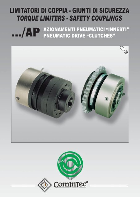
LIMITATORI DI COPPIA - GIUNTI DI SICUREZZA<br />
TORQUE LIMITERS - SAFETY COUPLINGS<br />
AZIONAMENTI PNEUMATICI “INNESTI”<br />
.../AP PNEUMATIC DRIVE “CLUTCHES”<br />
I GB<br />
OMC<br />
BOLOGNA<br />
R<br />
ITALY
OMC<br />
BOLOGNA<br />
ITALY<br />
LIMITATORI DI COPPIA - GIUNTI DI SICUREZZA<br />
TORQUE LIMITERS - SAFETY COUPLINGS<br />
INDICE - TABLE OF CONTENTS<br />
ESEMPI E APPLICAZIONI - EXAMPLES AND APPLICATIONS<br />
SCELTA DEL LIMITATORE<br />
SELECTING OF TORQUE LIMITER . . . . . . . . . . . . . . . . . . . . . . . . . . . . . . . . . . . . . . . . . . . . . . . . . . . . . . . . . . . . . . . . . . . . . . . . . . . p.03<br />
CARATTERISTICHE TECNICHE - VELOCITA' MASSIME DI ROTAZIONE - MODALITA' DI MONTAGGIO<br />
TECHNICAL SPECIFICATIONS - MAXIMUM ROTATION SPEEDS - FITTING INSTRUCTIONS<br />
. . . . . . . . . . . . . . . . . . . . . . . . p.04<br />
ESEMPI DI MONTAGGIO E APPLICAZIONI PER TRASMISSIONE DEL MOTO AD ALBERI PARALLELI E COASSIALI<br />
. . . . . . . . . . . . . . . p.05<br />
EXAMPLES OF FITTING AND APPLICATIONS TO PARALLEL AND SHAFTS-TO-SHAFT MOTION TRANSMISSION<br />
APPLICAZIONI SPECIALI<br />
. . . . . . . . . . . . . . . . . . . . . . . . . . . . . . . . . . . . . . . . . . . . . . . . . . . . . . . . . . . . . . . . . . . . . . . . . . . . . . . . . . p.06<br />
SPECIAL APPLICATIONS<br />
Linea / Line DSR/F/AP<br />
Dispositivo di sicurezza a rulli fase ad azionamento pneumatico<br />
Timing rollers pneumatic <strong>safety</strong> device<br />
DSR/F/AP Modello base - Base model . . . . . . . . . . . . . . . . . . . . . . . . . . . . . . . . . . . . . . . . . . . . . . . P.08 - 09<br />
Brevettato<br />
Patented<br />
Accoppiamenti GIUNTI con linea DSR/F/AP<br />
COUPLING connections DSR/F/AP line<br />
GEC Accoppiamento giunto GEC con DSR/F/AP - GEC coupling connection with DSR/F/AP<br />
Brevettato<br />
Patented<br />
Codifica - Codification . . . . . . . . . . . . . . . . . . . . . . . . . . . . . . . . p.10<br />
Caratteristiche tecniche - Technical characteristics . . . . . . . . p.10<br />
GTR Accoppiamento giunto GTR con DSR/F/AP - GTR coupling connection with DSR/F/AP<br />
Codifica - Codification . . . . . . . . . . . . . . . . . . . . . . . . . . . . . . . . p.11<br />
Caratteristiche tecniche - Technical characteristics . . . . . . . . p.11<br />
Dispositivo di sicurezza a scivolamento; tensionatore freno ad azionamento pneumatico<br />
Linea / Line DSF/TF/AP Sliding <strong>safety</strong> device; tension controlling brake pneumatic drive<br />
DSF/TF/AP Modello base - Base model. . . . . . . . . . . . . . . . . . . . . . . . . . . . . . . . . . . . . . . . . . . . . . . p.12 - 13<br />
Brevettato<br />
Patented<br />
Accoppiamenti GIUNTI con linea DSF/TF/AP<br />
COUPLING connections with DSF/TF/AP line<br />
TAC Accoppiamento giunto TAC con DSF/TF/AP - TAC coupling connection with DSF/TF/AP<br />
Codifica - Codification . . . . . . . . . . . . . . . . . . . . . . . . . . . . . . . . p.14<br />
Caratteristiche tecniche - Technical characteristics . . . . . . . . p.14<br />
2<br />
GEC Accoppiamento giunto GEC con DSF/TF/AP - GEC coupling connection with DSF/TF/AP<br />
Brevettato<br />
Patented<br />
Codifica - Codification . . . . . . . . . . . . . . . . . . . . . . . . . . . . . . . . p.15<br />
Caratteristiche tecniche - Technical characteristics . . . . . . . . p.15<br />
CARATTERISTICHE GENERALI - GENERAL CHARACTERISTICS<br />
DETERMINAZIONE DELLA BOCCOLA E SCELTA DELLA CORONA<br />
DIMENSIONING OF THE BUSHING AND CHOSEN OF THE PLATE WHEEL . . . . . . . . . . . . . . . . . . . . . . . . . . . . . . . . . . . . . . . . . . . . . . P.16<br />
DETERMINAZIONE E REGOLAZIONE DELLA COPPIA<br />
DETERMINATION AND ADJUSTMENT OF TORQUE . . . . . . . . . . . . . . . . . . . . . . . . . . . . . . . . . . . . . . . . . . . . . . . . . . . . . . . . . . . . . P.17
LIMITATORI DI COPPIA - GIUNTI DI SICUREZZA<br />
TORQUE LIMITERS - SAFETY COUPLINGS<br />
OMC<br />
BOLOGNA<br />
ITALY<br />
SCELTA DEL LIMITATORE / SELECTING OF TORQUE LIMITER<br />
In questa tabella sono elencate le principali caratteristiche dei vari limitatori<br />
di coppia pneumatici inseriti in questo catalogo.<br />
Queste indicazioni possono risultare utili per la scelta del giunto più<br />
appropriato in funzione dell'applicazione richiesta.<br />
In caso di particolari condizioni di utilizzo, non esitate a chiamare il<br />
nostro ufficio tecnico.<br />
This table shows the main characteristics of the various pneumatic <strong>torque</strong><br />
<strong>limiters</strong> included in this catalog.<br />
These indications may be useful for choosing the most appropriate coupling<br />
on the basis of the required application.<br />
In cases of particular utilization conditions, do not hesitate to call our<br />
technical office.<br />
Caratteristiche delle versioni ...<br />
Version characteristics...<br />
DSR/F/AP<br />
Versioni / Versions<br />
DSR/F/AP/CS<br />
DSF/TF/AP<br />
DSF/TF/AP/SI<br />
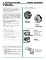
Possibilità di disinnesto completo della trasmissione anche per lunghi periodi<br />
Possibility of complete disengage of the transmission also for long period<br />
Trasmissione del moto per attrito con funzioni di tensionatore e freno<br />
Motion transmission for friction with tension controlling and brake function<br />
Trasmissione del moto per attrito con segnalazione e/o arresto dell’impianto al minimo scivolamento<br />
Motion transmission for friction with signalling and/or stop of the plant at the minimum sliding<br />
Segnalazione elettromeccanica del sovraccarico e reinnesto automatico della trasmissione<br />
con mantenimento della fase tra albero motore e albero condotto<br />
Electromechanical signalling of the overload and automatic re-engage of the transmission<br />
with timing keeping between the driving and the driven shaft<br />
<br />
<br />
<br />
<br />
®<br />
Alcuni suggerimenti sull’impiego dei giunti di sicurezza OMC (innesti pneumatici) suddivisi per settore<br />
Some suggestions on the use of OMC (pneumatic clutches) afety <strong>couplings</strong> divided by sector<br />
Macchine automatiche con cicli di lavorazione a coppia variabile<br />
e/o elevati spunti di partenza<br />
Automatic machines with cycle of production at variable couple<br />
and/or high start pick up.<br />
DSR/F/AP<br />
Macchine per avvolgimento/svolgimento di bobine<br />
(dove necessita una variazione costante della velocità e della coppia)<br />
Coil-winding / coil-unwinding machines (where it's necessary a costant<br />
speed variation and <strong>torque</strong>)<br />
DSF/TF/AP<br />
SIGNIFICATO DELLE SIGLE - ABBREVIATION MEANINGS<br />
DSR/F/AP:<br />
DSF/TF/AP:<br />
Dispositivo di sicurezza a rulli fase ad azionamento pneumatico<br />
Timing rollers pneumatic <strong>safety</strong> device<br />
Dispositivo di sicurezza a frizione, tensionatore freno, ad azionamento pneumatico<br />
Clutch <strong>safety</strong> device, tension controlling brake, pneumatic drive<br />
GTR/S:<br />
Giunto torsionalmente rigido semplice - Simply torsionally rigid coupling<br />
GTR/D: Giunto torsionalmente rigido doppio - Double torsionally rigid coupling<br />
TAC:<br />
Trasmissione assiale a catena - Chain axial transmission<br />
EM-1:<br />
microinterruttore elettromeccanico a leva regolabile a 1 contatto<br />
1 contact adjustable lever electromechanical switch<br />
EM-2:<br />
microinterruttore elettromeccanico a leva regolabile a 2 contatti<br />
2 contacts adjustable lever electromechanical switch<br />
... /SI/RA: segnalazione intervento reinnesto automatico - Automatic re-engagement intervention signalling<br />
PRX: s ensore induttivo di proximità - proximity inductive sensor<br />
La OMC (COMINTEC) si riserva il diritto di cessare la produzione di qualsiasi<br />
modello o di variarne specifiche o disegni in ogni momento senza preavviso e senza<br />
incorrere in obblighi.<br />
I dati riportati nel presente catalogo sono indicativi e non impegnativi.<br />
Il presente catalogo annulla e sostituisce i precedenti.<br />
OMC (COMINTEC) reserve the right to stop the production of any models or to<br />
change technical specification and dimensions in every moment without notice and<br />
without incur in obligations.<br />
All information given in this catalogue are only guideline information and cannot be<br />
regarded as binding.<br />
3
OMC<br />
BOLOGNA<br />
ITALY<br />
LIMITATORI DI COPPIA - GIUNTI DI SICUREZZA<br />
TORQUE LIMITERS - SAFETY COUPLINGS<br />
QUALITA’ DEL PRODOTTO / PRODUCT QUALITY<br />
L’elevata qualità dei prodotti illustrati in questo<br />
catalogo, sono il risultato di un processo che<br />
parte dal progetto strettamente basato su dati<br />
ricavati da prove sperimentali, si sviluppa con<br />
un'accurata scelta dei materiali e si avvale di<br />
procedure di controllo durante tutto il processo<br />
produttivo.<br />
La OMC allo scopo, oltre ad avvalersi dei<br />
laboratori del CERMET e dell'università Bologna,<br />
ha realizzato un banco prova interno (BP5000)<br />
sul quale vengono sistematicamente effettuati in<br />
tempo reale una serie di test sui principali<br />
componenti dei gruppi DSS-DSR e DSF.<br />
1) prove di durezza e di resistenza alla<br />
compressione dei rulli e delle sfere<br />
2) prove di tenuta e di carico delle<br />
piste di rotolamento per i rulli e le<br />
sfere;<br />
Il mantenimento di questi valori entro campi<br />
prestabiliti è condizione necessaria per<br />
garantire una buona durata del gruppo nel<br />
tempo per un considerevole numero di<br />
manovre.<br />
L'azienda certificata UNI EN ISO 9001-94 dal<br />
1996, e dal 2003 UNI EN ISO 9001-2000, opera<br />
con una finalità precisa: cercare la<br />
soddisfazione del cliente, personalizzando<br />
anche i vari prodotti affinché possano trovare<br />
sbocco nelle diverse aree applicative.<br />
The high quality of the products illustrated in this<br />
catalogue is the result of a process that starts<br />
from the design, strictly based on data obtained<br />
from experimental data, develops with a precise<br />
choice of materials, and makes use of control<br />
procedures throughout the entire production<br />
process.<br />
For this purpose OMC, in addition to making use<br />
of the CERMET laboratories and the University<br />
of Bologna, has also created an in-house test<br />
bench (BP5000) on which a series of tests on<br />
the main components of the DSS-DSR-DSF<br />
units are systematically carried out in real time:<br />
1) Hardness and compression tests<br />
on rollers and balls.<br />
2) Tightness and load tests on the rolling<br />
tracks for rollers and balls.<br />
It is necessary to keep these values within<br />
pre-set fields in order to guarantee a long<br />
life of the unit for a considerable number<br />
of operations.<br />
The company, certified UNI EN ISO 9001-94<br />
since 1996 and UNI EN ISO 9001-2000 since<br />
2003, operates with a specific aim: to seek<br />
customer satisfaction, even customizing its<br />
various products so that they can find an<br />
outlet in the different application areas.<br />
VELOCITA’ MASSIME DI ROTAZIONE / MAXIMUM ROTATION SPEEDS<br />
Poiché nei dispositivi di sicurezza OMC non avviene un disinnesto<br />
meccanico (radiale), la velocità di rotazione non ha una incidenza<br />
rilevante sul buon funzionamento degli stessi.<br />
E' opportuno invece tenere conto di altre variabili che combinate con la<br />
velocità stessa incidono maggiormente sulla durata del limitatore a<br />
frizione:<br />
1) il valore di coppia da trasmettere in rapporto al campo previsto del<br />
limitatore<br />
2) l'eventuale frequenza e durata degli slittamenti dovuti a sovraccarico.<br />
3) La possibilità di dissipare il calore generato dagli stessi slittamenti.<br />
Per queste ragioni le velocità massime indicate su questo catalogo, sono<br />
puramente indicative e da valutare dopo avere analizzato nella sua<br />
totalità tutte le variabili presenti nella catena cinematica.<br />
E' importante sottolineare che qualsiasi sia la velocità di rotazione in<br />
caso di slittamento dovuto a sovraccarico, è sempre indispensabile<br />
arrestare la trasmissione nel più breve tempo possibile, per ottenere<br />
una durata prolungata e una maggiore efficienza dei dispositivi di<br />
sicurezza.<br />
In the OMC's <strong>safety</strong> devices there is no mechanical (radial)<br />
disengagement. Thus, rotation speed has a minor incidence on the<br />
smooth operation of these devices.<br />
There are other variables which, if combined to the same speed, have a<br />
greater incidence on the life of the friction limiter:<br />
1. the <strong>torque</strong> to be transmitted in relation to the expected field of the<br />
limiter,<br />
2. the possible frequency and duration of the sliding due to overload,<br />
3. the possibility of loosing the heat generated by the same sliding.<br />
For these reasons the maximum speeds shown in this catalogue are a<br />
mere indication and must be evaluated after analyzing the overall<br />
variables in the kinematic chain.<br />
It is important to underline that whatever the rotation speed in the<br />
case of sliding due to overload, the transmission must be stopped<br />
as soon as possible, in order to obtain longer life and greater<br />
efficiency of the <strong>safety</strong> devices.<br />
MODALITA’ DI MONTAGGIO / FITTING INSTRUCTIONS<br />
E ' consigliabile montare il dispositivo di sicurezza preferibilmente<br />
sull 'albero lento della trasmissione da proteggere da sovraccarico.<br />
Il fissaggio del dispositivo può essere effettuato assialmente con vite e<br />
rondella e radialmente con grano sulla linguetta oppure mediante<br />
calettatori (vedi esempi di montaggio a pag.29).<br />
Il foro finito (a richiesta)è fornito con tolleranza H7 e cava per la linguetta<br />
secondo UNI 6604 con tolleranza H9.<br />
Se il dispositivo viene fornito con foro grezzo, sarà a carico<br />
dell 'utilizzatore la cura della tolleranza e centratura in fase di<br />
esecuzione del foro finito.<br />
L’assemblaggio non corretto del gruppo ed in particolare delle molle, ne<br />
pregiudica il corretto funzionamento.<br />
Il perno anti-rotante del gruppo cilindro non deve essere bloccato in<br />
modo rigido perché potrebbe essere causa di alcuni squilibri<br />
durante la rotazione dello stesso.<br />
The <strong>safety</strong> device should be assembled preferably on the slow<br />
transmission shaft to prevent overload.<br />
The device can be fixed axially by screw and washer and, radially by a<br />
dowel on the spline or by locking assemblies (see examples of fitting on<br />
page 29).<br />
The finished bore (upon request) is supplied in H7 tolerance and with a<br />
keyway for the spline in compliance with UNI 6604 (DIN6885) with H9<br />
tollerance. If the device is supplied with pilot bore, the user shall take care<br />
of both tolerance and centering when finishing the bore.<br />
The proper operation is prevented by the inappropriate assembly of the<br />
group, and especially of the springs.<br />
The rotation damper pin of the cylinder group not must to be locked<br />
in a rigid manner because it could be cause of some unbalances<br />
during the rotation of the same one.<br />
4
LIMITATORI DI COPPIA - GIUNTI DI SICUREZZA<br />
TORQUE LIMITERS - SAFETY COUPLINGS<br />
OMC<br />
BOLOGNA<br />
ITALY<br />
ESEMPI DI MONTAGGIO E APPLICAZIONE PER TRASMISSIONE DEL MOTO AD ALBERI PARALLELI<br />
EXAMPLES OF ASSEMBLY AND APPLICATIONS FOR MOTION TRANSMISSION TO PARALLEL SHAFT<br />
DSR/F/AP: modello base con puleggia dentata<br />
DSR/F/AP: base model with timing belt pulley<br />
DSF/TF/AP: modello base con corona doppia<br />
DSF/TF/AP: base model with double plate wheel<br />
( Vedi pagina 9 / See page 9 ) ( Vedi pagina 13 / See page 13 )<br />
ESEMPI DI MONTAGGIO E APPLICAZIONE PER TRASMISSIONE DEL MOTO AD ALBERI COASSIALI<br />
EXAMPLES OF ASSEMBLY AND APPLICATIONS FOR MOTION TRANSMISSION TO SHAFT TO SHAFT<br />
DSR/F/AP + GTR<br />
( Vedi pagina 11 / See page 11)<br />
DSF/TF/AP + TAC<br />
( Vedi pagina 14 / See page 14 )<br />
DSR/F/AP + GEC<br />
DSF/TF/AP + GEC<br />
( Vedi pagina 10 - See page 10 ) ( Vedi pagina 15 - See page 15 )<br />
5
OMC<br />
BOLOGNA<br />
ITALY<br />
LIMITATORI DI COPPIA - GIUNTI DI SICUREZZA<br />
TORQUE LIMITERS - SAFETY COUPLINGS<br />
DSR/F/AP<br />
APPLICAZIONI SPECIALI - SPECIAL APPLICATIONS<br />
DISPOSITIVO DI SICUREZZA AD AZIONAMENTO PNEUMATICO CON CUSCINETTI A SFERE (DSR/F/AP/CS)<br />
PNEUMATIC SAFETY DEVICE WITH BALL BEARINGS (DSR/F/AP/CS)<br />
la versione con cuscinetti a sfere in alternativa<br />
alle gabbie a rullini, consente una maggiore e<br />
migliore scorrevolezza delle parti scollegate ed è<br />
molto utile in particolari condizioni di lavoro, dove<br />
oltre alla funzione di limitatore di coppia è<br />
richiesto al dispositivo anche la funzione di<br />
innesto/disinnesto completo della trasmissione<br />
per lunghi periodi con conseguente rotazione<br />
libera di una parte dello stesso.<br />
The model with ball-bearings in alternative<br />
toroller cages, allows a higher and better<br />
smoothness of the disassembled parts and it is<br />
very useful under particular working conditions,<br />
where it is required together with the function of<br />
<strong>torque</strong> limiter, the function of complete<br />
clutch/disconnection of the transmission for long<br />
periods with following free rotation of a part of it.<br />
STAFFA PER PRX - BRACKET FOR PRX<br />
Tutti i modelli ad azionamento pneumatico sono<br />
predisposti per il montaggio di un apposita<br />
staffa (fornita a richiesta) dimensionata per il<br />
montaggio di sensori di prossimità PRX M8 in<br />
configurazione normalmente chiusa (N.C.) o<br />
normalmente aperta (N.O.).<br />
Per le caratteristiche tecniche del proximity vedi<br />
pag.20<br />
N.C.<br />
N.O.<br />
All versions with pneumatic operation are<br />
prearranged for the assemble of a suitable<br />
bracket (supplied on request) dimensioned for<br />
the assembly of sensors of PRX M8 proximity in a<br />
normally close (NC) or normally opened (NO)<br />
configuration.<br />
For the technical features about proximity see<br />
page.20<br />
SISTEMI DI BLOCCAGGIO ALTERNATIVI - ALTERNATIVE LOCKING SYSTEMS<br />
Bloccaggio con calettatore esterno<br />
Locking with external locking assemblies<br />
Bloccaggio a morsetto con CFBR - CFBR/2<br />
Locking with clamp collars CFBR - CFBR/2<br />
6
LIMITATORI DI COPPIA - GIUNTI DI SICUREZZA<br />
TORQUE LIMITERS - SAFETY COUPLINGS<br />
OMC<br />
BOLOGNA<br />
ITALY<br />
APPLICAZIONI SPECIALI - SPECIAL APPLICATIONS<br />
DSF/TF/AP<br />
MODELLO CON SEGNALAZIONE INTERVENTO REINNESTO AUTOMATICO (DSF/TF/AP/SI/RA)<br />
INTERVENTION SIGNALLING MODEL WITH AUTOMATIC REENGAGE (DSF/TF/AP/SI/RA)<br />
Fino a ieri i modelli a frizione con<br />
segnalazione intervento "SI"<br />
presentavano una notevole difficoltà nel<br />
ripristino del sistema dopo uno<br />
slittamento da sovraccarico, perché per<br />
effettuare il reinnesto era necessario<br />
liberare l'organo di trasmissione,<br />
riportarlo nella corretta posizione di<br />
reinnesto e successivamente<br />
ripristinare la taratura precedente.<br />
Queste operazioni comportano tempi<br />
lunghi di esecuzione, specialmente se il<br />
dispositivo si trova in posizioni poco<br />
accessibili.<br />
La OMC ha realizzato su questi gruppi<br />
un sistema innovativo dove non è<br />
necessario liberare l'organo per<br />
ripristinare la trasmissione, perché il<br />
reinnesto è automatico e dopo avere<br />
eliminato la causa del sovraccarico<br />
l'avvio dell'impianto è immediato,<br />
premendo semplicemente il pulsante<br />
start.<br />
N.B.: la particolarità che conferisce al<br />
gruppo questa caratteristica, consiste in<br />
una speciale lavorazione che viene<br />
effettuata sull'organo di trasmissione,<br />
pertanto è presente solo ed<br />
esclusivamente se il gruppo viene<br />
fornito completo di organo di<br />
trasmissione.<br />
Till yesterday, the friction models with<br />
intervention signalling SI, had a lot of<br />
difficulties to reset the system after a<br />
slipping caused by overload, in fact to<br />
carry out the re-engagement, it was<br />
necessary to release the transmission<br />
organ, bring it again in the right clutch<br />
position and reset the previous<br />
calibration.<br />
It is necessary a lot of time to carry out<br />
these procedures, especially if the<br />
device is in an uncomfortable place, not<br />
easy accessible.<br />
OMC has realised on these groups a<br />
new system where it is not necessary to<br />
release the organ to reset the<br />
transmission because the clutch is<br />
automatic and after having eliminated<br />
the cause of overload, the running of<br />
the plant is immediate, simply pressing<br />
start.<br />
N.B.: the particular detail of this group<br />
is a special working carried out on the<br />
transmission body, therefore it is<br />
possible only if the unit is supplied<br />
complete with transmission organ.<br />
STAFFA PER PRX - BRACKET FOR PRX<br />
Un prolungato slittamento dovuto a<br />
sovraccarico nel limitatore a frizione<br />
provoca surriscaldamento di tutti i suoi<br />
componenti, una maggiore usura degli<br />
anelli di attrito e una modifica del<br />
coefficiente di attrito limitandone la<br />
durata e la ripetitività.<br />
Per mantenere costante il rendimento<br />
del limitatore e garantirne la massima<br />
durata, è consigliabile fermare<br />
l'impianto al primo cenno di slittamento.<br />
In alternativa al modello<br />
DSF/TF/AP/SI/RA è possibile utilizzare<br />
il segnale elettrico di un sensore<br />
induttivo di prossimità che rileva una<br />
qualsiasi variazione anomala della<br />
velocità come indicato nell'esempio in<br />
A prolonged slipping caused by<br />
overload in the friction limiter causes an<br />
over warming of the components, a<br />
higher wear of the friction rings and a<br />
change of the friction coefficient,<br />
limiting the duration and repetitiveness.<br />
It is recommended to stop the plant at<br />
the first sliding signs to maintain the<br />
limiter performance constant and<br />
guarantee a long duration.<br />
In alternative to the model<br />
DSF/TF/AP/SI/RA it is possible to use<br />
an electric signal of a proximity<br />
inductive sensor which notes any<br />
abnormal variations of the speed as<br />
indicated in the example of the picture.<br />
7
OMC<br />
BOLOGNA<br />
ITALY<br />
DSR/F/AP<br />
LIMITATORI DI COPPIA - GIUNTI DI SICUREZZA<br />
TORQUE LIMITERS - SAFETY COUPLINGS<br />
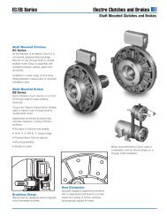
DISPOSITIVO DI SICUREZZA A RULLI FASE AD AZIONAMENTO PNEUMATICO<br />
TIMING ROLLER PNEUMATIC SAFETY DEVICE<br />
Questo prodotto, coperto da brevetto Italiano di utilità n°238.205 del 16/10/2000, viene attualmente<br />
realizzato in 7 grandezze e ricopre un campo di coppia variabile da 7 a 30000 Nm, con possibilità di<br />
alloggiare alberi da ø8 a ø120 mm. Mantiene la medesima tipologia di funzionamento e di<br />
montaggio dei limitatori a rulli fase tradizionali (DSR/F), innesto sincrono con distribuzione<br />
angolare dei rulli (BREVETTATA), che rappresenta la soluzione matematicamente ottimale<br />
per avere un sicuro appoggio equilibrato in tutte le posizioni possibili nell'arco dei 360°, sul<br />
quale vengono sostituite molle e ghiera di regolazione con un gruppo cilindrico ad<br />
azionamento pneumatico mantenendo invariati: valori di coppia; ingombri radiali;<br />
calettaggi ed interassi di collegamento.<br />
Inoltre l'utilizzo delle gabbie a rullini e del cuscinetto reggispinta garantiscono una<br />
perfetta scorrevolezza in quanto assorbono le forze radiali e le forze assiali<br />
indotte dal cilindro, con ingombri contenuti.<br />
Si possono distinguere due diversi principi di funzionamento:Limitatore<br />
di coppia ad azionamento pneumatico<br />
• possibilità di variazione della coppia anche durante il moto<br />
per vincere gli spunti di partenza agendo sul regolatore di<br />
pressione;<br />
• perfetto distacco delle parti durante il disinnesto per<br />
sovraccarico con rotazione libera ed assenza di<br />
coppia residua;<br />
• reinnesto con macchina in movimento.<br />
Giunto ad innesto / disinnesto ad azionamento<br />
pneumatico<br />
• stesse caratteristiche del punto precedente<br />
• la parte motrice e la parte<br />
condotta possono essere<br />
innestate e disinnestate<br />
pneumaticamente<br />
permettendo anche<br />
una rotazione<br />
libera folle per<br />
periodi di<br />
tempo<br />
prolungati.<br />
This<br />
product<br />
that has an<br />
utility Italian<br />
patent No.238.205<br />
dated 16/10/2000, is<br />
introduced and available<br />
in seven different sizes and<br />
include a variable <strong>torque</strong> field<br />
from 7Nm to 30000 Nm, with shaft<br />
diameters from ø8 mm to ø120 mm.<br />
It maintains the same typology of<br />
operation and assembly of traditional rollers<br />
device (DSR/F), synchronous clutch with the<br />
rollers angular distribution (PATENTED) whose<br />
represents the suitable solution to achieve an<br />
equilibrate good support in all possible positions within<br />
360°; in which springs and adjusting ring nuts have been<br />
replaced by a suitable pneumatic cylinder, while keeping the<br />
following parameters unchanged: <strong>torque</strong> values; radial overall<br />
dimensions; connection references. Moreover the utilization of<br />
the roller cages and the thrust bearings ensure utmost smoothness, as<br />
they absorb the radial forces and the axial forces originated by the cylinder,<br />
with reduced overall dimensions.<br />
Two various principles of operation can be distinguished:<br />
Pneumatic <strong>safety</strong> device<br />
- Possibility of changing the transmissible <strong>torque</strong> also during running in order to<br />
counteract take-offs by simply adjusting pressure.<br />
- Perfect detachment of the parts during the release due to overload with<br />
free rotation and absence of residual <strong>torque</strong>;<br />
- Reengage during machine running;<br />
CON S OLI 350 m m DI DIAMETRO TRASMETTIA MO FINO A 30000 N m D I COPPIA<br />
Pneumatic coupling with engagement /disengagement<br />
- Same characteristics of the point “1”<br />
- The part engine and the driven part can pneumatically be engaged and<br />
disengaged allowing also a free rotation for long periods.<br />
WI TH ONL Y A DIAM ETER OF 350 mm WE TRANSMIT UP TO 30000 Nm OF TORQUE<br />
8<br />
Grand.<br />
Size<br />
Standard<br />
Coppia - Torque<br />
(Nm)<br />
A richiesta<br />
On request<br />
1 - 6 bar 10 bar 15 bar<br />
0.56 7-29 45 70<br />
Caratteristiche tecniche - Technical characteristics<br />
Taratura<br />
Setting<br />
(Bar-Nm)<br />
Peso (ø grezzo)<br />
Weight (ø rough)<br />
(Kg)<br />
Inerzia (ømax) - Inertia (ømax)<br />
(Kgm 2 )<br />
Lato flangia<br />
flange side<br />
lato mozzo<br />
hub side<br />
Velocità max<br />
Max speed<br />
(Rpm)<br />
1,5 0,00015 0,00030 11000<br />
1.90 20-115 185 280 5,0 0,00179 0,00260 7000<br />
2.110 15-195 330 480 9,0 0,00512 0,00683 5000<br />
3.130 25-310 520 780 13,3 0,01092 0,01413 4300<br />
4.160 55-530 900 1335 vedi pag.18<br />
19,0 0,03088 0,03879 3600<br />
5.194 330-1600 2600 3970 see page 18<br />
35,8 0,05957 0,09306 3200<br />
6.240 CB 1100-5800 (Max 6 bar)<br />
6.240 CA 3400-15000 (Max 5 bar)<br />
7.280 CB 1500-7500 (Max 6 bar)<br />
7.280 CA 7000-30000 (Max 6 bar)<br />
A richiesta - On request
LIMITATORI DI COPPIA - GIUNTI DI SICUREZZA<br />
TORQUE LIMITERS - SAFETY COUPLINGS<br />
OMC<br />
BOLOGNA<br />
ITALY<br />
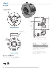
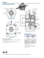
MODELLO BASE - BASE MODEL<br />
DSR/F/AP<br />
IN ACCIAIO UNI EN 10084/98 INTERAMENTE LAVORATO<br />
IN STEEL ACC.TO UNI EN 10083/98 FULL TURNED<br />
Dimensioni standard - Standard dimensions<br />
Grand.<br />
Size<br />
A<br />
A richiesta<br />
On request<br />
Flangia standard<br />
standard flange<br />
D H7<br />
B h7 G P T øMax<br />
F J M N U V Z X Y<br />
0.56 56 38 10 6xM5 48 18 56 56 97 45 11,5 1/8 Gas 7,5 6 63<br />
1.90 90 50 18 6xM5 70 25 90 67,5 128 60 16 1/4 Gas 12 6 80<br />
2.110 110 60 20 6xM6 89 38 110 85 148 70 18,5 1/4 Gas 13 8 105<br />
3.130 130 80 19 6xM8 105 45 130 90,5 160 100 20,5 1/4 Gas 14,5 8 115<br />
4.160 160 100 22 6xM10 125 55 160 109 192 115 25 1/4 Gas 17 10 146<br />
5.194 194 120 26 6xM12 155 65 215 125 202 145 30 1/4 Gas 18 12 184<br />
6.240 CB 240 6xM16 200 90 290 305<br />
A richiesta<br />
On request<br />
6.240 CA 240 6xM16 200 90 290 355<br />
7.280 CB 280 6xM20 230 120 345 320<br />
7.280 CA 280 6xM20 230 120 345 375<br />
A richiesta<br />
On request<br />
Tav.1 - Tab.1<br />
DSR/F<br />
0.56 153<br />
1.90 158<br />
2.110 163<br />
3.130 168<br />
4.160 173<br />
5.194 178<br />
6.240 183<br />
7.280 188<br />
Tavola 1a<br />
Table 1a<br />
modello standard<br />
standard model<br />
99<br />
6.240 e 7.280 "CB" 88<br />
6.240 e 7.280 "CA" 98<br />
Tavola 2<br />
Table 2<br />
Cilindro<br />
standard<br />
Standard<br />
cylinder<br />
Codifica DSR/F/AP code<br />
P<br />
Tavola 3<br />
Table 3<br />
flangia<br />
standard<br />
standard<br />
flange<br />
flange speciali<br />
a richiesta<br />
special flange<br />
on request<br />
2<br />
...<br />
Tavola 4<br />
Table 4<br />
nessuna applicazione<br />
no application<br />
00<br />
Tavola 5<br />
Table 5<br />
Foro finito<br />
Finished bore<br />
nnn<br />
Esempio di codifica<br />
Example of codification<br />
Codice / Code 163 99 P 2 00 030<br />
2.110 DSR/F/AP - foro finito ø30<br />
2.110 DSR/F/AP finished bore ø30<br />
NOTE - NOTES<br />
Per pressioni superiori ai 6 bar e coppie maggiori, consultare il nostro ufficio tecnico.<br />
For pressure over 6 bar and higher <strong>torque</strong>s, please contact our technical department.<br />
Prodotto disponibile esclusivamente con foro finito.<br />
This product is available only with finished bore.<br />
9
OMC<br />
BOLOGNA<br />
ITALY<br />
GEC<br />
LIMITATORI DI COPPIA - GIUNTI DI SICUREZZA<br />
TORQUE LIMITERS - SAFETY COUPLINGS<br />
ACCOPPIAMENTO GIUNTO “GEC” CON DSR/F/AP<br />
“GEC” COUPLING CONNECTION WITH DSR/F/AP<br />
IN ACCIAIO UNI EN 10084/98 INTERAMENTE LAVORATO<br />
IN STEEL ACC.TO UNI EN 10083/98 FULL TURNED<br />
Grand. / Size<br />
DSR/F/AP<br />
GEC<br />
Elem. elastico nero<br />
Black elastic element<br />
GEC + DSR/F/AP: dimensioni standard - standard dimensions<br />
Codice - Code<br />
Elem. elastico verde<br />
Green elastic element<br />
A3<br />
D3<br />
E3 H7<br />
Ø Grezzo<br />
Ø Rough<br />
M3 N3 Q3<br />
D H7<br />
F K R Y<br />
0.56 0 200661000000 200667000000 78 50 10 28 63,5 32 28 18 56 79 142 63<br />
1.90 1 200671000000 200677000000 108 70 12 38 89 49 44 25 90 79 189 80<br />
2.110 2 200681000000 200687000000 130 80 15 45 111 65 59 38 110 93 229 105<br />
3.130 3 200691000000 200697000000 161 100 15 60 140 85 77 45 130 82,5 268 115<br />
4.160 4 200701000000 200707000000 206 120 20 70 168 105 97 55 160 103 323 146<br />
5.194 5 200711000000 20071700000 239 135 30 80 201 130 120 65 194 86 361 184<br />
6.240 CB<br />
6.240 CA<br />
7.280 CB<br />
7.280 CA<br />
6<br />
7<br />
Ø Max<br />
A richiesta - On request<br />
Ø Max<br />
DSR/F/AP<br />
Grand. - Size<br />
Coppia Max<br />
Max <strong>torque</strong><br />
(Nm)<br />
Grand. - Size<br />
GEC<br />
Coppia Nom<br />
Nom <strong>torque</strong><br />
(Nm)<br />
Peso (øgrezzo) - Weight (ørough)<br />
(Kg)<br />
GEC + DSR/F/AP : caratteristiche tecniche - technical specifications<br />
Inerzia (ø max)<br />
Inertia (ø max)<br />
(Kgm 2<br />
)<br />
Velocità max<br />
Max speed<br />
(Rpm)<br />
Temp. max Durezza<br />
Max temp. Hardness<br />
(°C) (Sh-A)<br />
Elemento elastico NERO<br />
BLACK elastic coupling<br />
Elemento elastico VERDE<br />
GREEN elastic coupling<br />
Elemento elastico NERO<br />
BLACK elastic coupling<br />
Elemento elastico VERDE<br />
GREEN elastic coupling<br />
continuo<br />
continuos<br />
intermittente<br />
intermittent<br />
Disallineamenti - Misalignments<br />
continuo<br />
continuos<br />
servizio - operation<br />
intermittente<br />
intermittent<br />
continuo<br />
continuos<br />
intermittente<br />
intermittent<br />
continuo - intermittente<br />
continuos - intermittent<br />
0.56 70 0 70 0,6 0,00090 5500<br />
1° 1° 30' ± 0,7 ± 1,5 0,5 0,7 2°<br />
1.90 280 1 280 1,6 0,00434 5000 0° 48' 1° ± 0,7 ± 1,5 0,5 0,7 2°<br />
2.110 480 2 570 2,7 0,01035 4500 100<br />
0° 36' 0° 48' ± 0,7 ± 1,5 0,6 0,7 1° 45'<br />
80<br />
3.130 780 3 980 5,5 0,02779 4000 ±10<br />
0° 30' 0° 42' ± 0,8 ± 1,6 0,6 0,8 1° 15'<br />
4.160 1335 4 2340 15,9 0,08528 3100 170<br />
0° 24' 0° 30' ± 0,8 ± 1,6 0,6 0,8 1°<br />
80<br />
5.194 3970 5 3880 18,5 0,20231 2800 ±10<br />
0° 24' 0° 30' ± 0,8 ± 1,6 0,6 0,8 1°<br />
6.240 CB 5800<br />
6 15000<br />
0° 24' 0° 30' ± 0,8 ± 1,6 0,6 0,8 1°<br />
6.240 CA 15000<br />
a richiesta<br />
- -<br />
7.280 CB 7500<br />
on request<br />
7 30000 0° 24' 0° 30' ± 0,8 ± 1,6 0,6 0,8 1°<br />
7.280 CA 30000<br />
NOTE - NOTES<br />
il CODICE è riferito alla sola applicazione giunto con foro grezzo (per il limitatore vedi pag.9)<br />
The CODES refer only to the coupling application with pilot bore (about the <strong>torque</strong> limiter see you page 9)<br />
Tutti i dati riportati nella tabella CARATTERISTICHE TECNICHE sono riferiti alla sola applicazione (per il limitatore vedi pag.9)<br />
All details showed in table TECHNICAL SPECIFICATIONS refer only to the application (about the <strong>torque</strong> limiter see you page 9)<br />
10
LIMITATORI DI COPPIA - GIUNTI DI SICUREZZA<br />
TORQUE LIMITERS - SAFETY COUPLINGS<br />
OMC<br />
BOLOGNA<br />
ITALY<br />
ACCOPPIAMENTO GIUNTO “GTR” CON DSR/F/AP<br />
“GTR” COUPLING CONNECTION WITH DSR/F/AP<br />
GTR<br />
IN ACCIAIO UNI EN 10084/98 INTERAMENTE LAVORATO<br />
IN STEEL ACC.TO UNI EN 10083/98 FULL TURNED<br />
GTR/D<br />
GTR/S<br />
GTR + DSR/F/AP : dimensioni standard - standard dimensions<br />
Grand. / Size<br />
E3 H7 E1 H7<br />
D H7<br />
A3 D3 D1<br />
N3 P3 Q3 V3 Z3<br />
DSR/F/AP GTR ø max ø max ø max<br />
F R Y K K1 W W1<br />
0.56 0 78 35 45 25 32 29 7,5 50 M5 10 18 56 143 63 69 105,5 56,5 93<br />
1.90 2 92 42 53 30 38 42 8 50 M5 10 25 90 179,5 80 77,5 101,5 70 94<br />
2.110 3 112 53 65 38 45 46 10 59 M8 15 38 110 209,5 105 93,5 127,5 82 116<br />
3.130 4 136 63 75 45 52 56 12 75 M8 15 45 130 234,5 115 78,5 122,5 94 138<br />
4.160 5 162 72 92 52 65 66 13 95 M8 20 55 160 283,5 146 102,5 159,5 114 171<br />
5.194 7 206 101 130 60 72 92 15 101 M10 20 65 194 317,5 184 80,5 121,5 142 183<br />
6.240 CB<br />
6.240 CA<br />
7.280 CB<br />
A richiesta - On request<br />
7.280 CA<br />
DSR/F/AP<br />
Grand.<br />
Size<br />
Coppia max<br />
Max <strong>torque</strong><br />
(Kgm )<br />
Grand.<br />
Size<br />
GTR<br />
Coppia nom<br />
Nom <strong>torque</strong><br />
(Kgm )<br />
GTR + DSR/F/AP: caratteristiche tecniche - technical specifications<br />
Coppia max<br />
Max orque<br />
(Kgm )<br />
Peso (ø grezzo)<br />
Weight (ø rough)<br />
(Kg)<br />
Inerzia (ø max)<br />
Inertia (ø max)<br />
(Kgm 2 )<br />
Velocità max<br />
Max speed<br />
(Rpm)<br />
Coppia serraggio<br />
Tightenings <strong>torque</strong><br />
(Nm)<br />
Disallineamenti - Misalignments<br />
GTR/S GTR/D GTR/S GTR/D GTR/S GTR/D GTR/S GTR/D GTR/D GTR/S GTR/D<br />
0.56 70 0 60 120 1,2 1,6 0,00088 0,00251 11000 12<br />
± 0,70 ± 1,40 0,70 80 42<br />
1.90 280 2 150 300 2,1 3,0 0,00246 0,00334 7000 13 ± 0,95 ± 1,90 0,79 156 71<br />
2.110 480 3 300 600 3,6 5,2 0,00549 0,00897 5000 22 ± 1,25 ± 2,50 0,95 415 184<br />
0° 45' 1° 30'<br />
3.130 780 4 700 1400 5,2 3,4 0,01171 0,01955 4300 39 ± 1,45 ± 2,90 1,18 970 422<br />
4.160 1335 5 1100 2200 8,8 12,8 0,02015 0,02606 3600 85 ± 1,65 ± 3,30 1,45 1846 803<br />
5.194 3970 7 2600 5200 18,8 25,0 0,09250 0,14694 3200 127 ± 2,25 ± 4,50 1,57 3511 1596<br />
6.240 CB 5800<br />
6.240 CA 15000<br />
7.280 CB 7500<br />
A richiesta - On request<br />
7.280 CA 30000<br />
NOTE - NOTES<br />
Tutti i dati riportati nella tabella CARATTERISTICHE TECNICHE sono riferiti alla sola applicazione (per il limitatore vedi pag.9)<br />
All details showed in table TECHNICAL SPECIFICATIONS refer only to the application (about the <strong>torque</strong> limiter see you page 9)<br />
11
OMC<br />
BOLOGNA<br />
ITALY<br />
DSF/TF/AP<br />
LIMITATORI DI COPPIA - GIUNTI DI SICUREZZA<br />
TORQUE LIMITERS - SAFETY COUPLINGS<br />
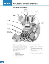
DISPOSITIVO DI SICUREZZA A FRIZIONE TENSIONATORE FRENO AD AZIONAMENTO PNEUMATICO<br />
FRICTION SAFETY DEVICE TENSION CONTROLLING BRAKE, PNEUMATIC DRIVE<br />
La OMC ha arricchito la sua gamma di dispositivi con il nuovo:<br />
DSF/TF/AP. Il dispositivo si compone di un limitatore di coppia a<br />
frizione al quale si e' sostituito il pacco di molle con un<br />
appropriato cilindro pneumatico.<br />
Le funzioni ottenibili da questa soluzione sono le seguenti:<br />
Limitatore di coppia<br />
• Assenza di manutenzione fino alla completa usura degli anelli di<br />
attrito.<br />
• Mantenimento costante della coppia in quanto la pressione sugli<br />
anelli rimane costante per l'autocompensazione della corsa in<br />
base all'usura.<br />
• Semplice taratura tramite regolazione della pressione (vedi<br />
figura sotto).<br />
• Variazione della coppia con macchina in movimento.<br />
Tensionatore e freno<br />
La funzione di tensionatore è importante quando si necessita<br />
mantenere costante la forza di tensionamento al variare del<br />
diametro di una bobina.<br />
Questo lo si ottiene variando la pressione in modo graduale<br />
all'interno del cilindro pneumatico, con valvola proporzionale<br />
tramite PLC.<br />
OMC has recently extended its range of devices with the new<br />
DSF/TF/AP. The device consists of a friction <strong>torque</strong> limiter whose<br />
axial spring have been replaced by a suitable pneumatic cylinder.<br />
The functions offered by this solution are as follows:<br />
Torque limiter device:<br />
• Maintenance free until complete friction rings wear;<br />
• Constant <strong>torque</strong> maintained since the pressure on the rings<br />
remains constant as a result of stroke self-compensation in<br />
accordance with wear.<br />
• Simple adjustment through pressure regulation (see picture<br />
below).<br />
• Torque adjustment whilst machine is running.<br />
Tension controlling and brake<br />
The tension controlling function is important when it's necessary<br />
to keep the tensioning force constant if changing reel diameter.<br />
This is obtained by altering gradually the internal pressure of the<br />
pneumatic cylinder, with proportional valve by PLC.<br />
For the brake function, the device is supplied with the maximum<br />
allowable pressure.<br />
Per la funzione freno si alimenta il dispositivo con la massima<br />
pressione ammessa.<br />
Grand.<br />
Size<br />
Coppia - Torque<br />
(Nm)<br />
0.50 2 - 20<br />
Caratteristiche tecniche - Technical characteristics<br />
Taratura - Setting<br />
(Bar-Nm)<br />
Peso (ø grezzo) - Weight (ø rough)<br />
(Kg)<br />
Velocità max - Max speed<br />
(Rpm)<br />
0,7 7600<br />
1.70 20 - 90 2,4 5450<br />
2.90 30 - 125 vedi pag.19<br />
4,3 4250<br />
3.115 40 - 220 see page 19<br />
7,0 3350<br />
4.140 50 - 350 11,9 2750<br />
5.170 200 - 805 19,8 2250<br />
12
LIMITATORI DI COPPIA - GIUNTI DI SICUREZZA<br />
TORQUE LIMITERS - SAFETY COUPLINGS<br />
OMC<br />
BOLOGNA<br />
ITALY<br />
MODELLO BASE - BASE MODEL<br />
DSF/TF/AP<br />
IN ACCIAIO UNI EN 10083/98 INTERAMENTE LAVORATO<br />
IN STEEL ACC.TO UNI EN 10083/98 FULL TURNED<br />
Grand.<br />
Size<br />
A<br />
B<br />
h7<br />
A richiesta<br />
Dimensioni standard - Standard dimensions<br />
On request<br />
D<br />
G<br />
Q<br />
F<br />
L M N S U V Z X Y<br />
ø max Min Max ømax<br />
0.50 50 36 19 56 3,5 6 11 62 10 3 11 1/8" 7 6 63 3,5 - M4<br />
1.70 70 45 25 90 5 10 15 85 15 4 15,5 1/4" 11,5 6 80 4,5 - M4<br />
2.90 90 60 38 110 7 12 16 95 17 4 16,5 1/4" 12,5 8 105 5 - M6<br />
3.115 115 72 45 130 9 16 18 112 21 4 16,5 1/4" 12,5 8 115 5 - M6<br />
4.140 140 85 55 160 11 19 20 128 25 5 24,5 1/4" 17 10 146 6 - M6<br />
5.170 170 98 65 215 15 22 22,5 140 28 5 26 1/4" 18 12 184 6,5 - M8<br />
Tavola 1<br />
Table 1<br />
Tavola 1a<br />
Table 1a<br />
Tavola 2<br />
Table 2<br />
Codifica DSF/TF/AP code<br />
Tavola 3<br />
Table 3<br />
Tavola 4<br />
Table 4<br />
Tavola 5<br />
Table 5<br />
0.50 101<br />
1.70<br />
2.90<br />
102<br />
3.115<br />
4.140 103<br />
DSF/TF/AP<br />
(1.70-3.115-5.170)<br />
DSF/TF/AP<br />
(0.50-2.90-4.140)<br />
01<br />
51<br />
Cilindro<br />
standard<br />
Standard<br />
cylinder<br />
9<br />
Nessuna<br />
applicazione<br />
No<br />
application<br />
K<br />
boccola standard<br />
standard bushing<br />
boccola + corona<br />
bushing + platewheel<br />
01<br />
vedi pag.16<br />
see pag.16<br />
Foro finito<br />
Finished bore<br />
nnn<br />
5.170 104<br />
Esempio di codifica<br />
Example of codification<br />
Codice / Code 102 01 9 K 01 020<br />
1.70 DSF/TF/AP - 1 boccola - foro finito ø20<br />
1.70 DSF/TF/AP - 1 bushing - finished bore ø20<br />
NOTE - NOTES<br />
Per pressioni superiori ai 6 bar e coppie maggiori, consultare il nostro ufficio tecnico.<br />
For pressure over 6 bar and higher <strong>torque</strong>s, please contact our technical department.<br />
NOTE - NOTES<br />
Prodotto disponibile esclusivamente con foro finito.<br />
Phis product is available only with finished bore.<br />
13
OMC<br />
BOLOGNA<br />
ITALY<br />
LIMITATORI DI COPPIA - GIUNTI DI SICUREZZA<br />
TORQUE LIMITERS - SAFETY COUPLINGS<br />
DSF/TF/AP/TAC<br />
MODELLO TRASMISSIONE ASSIALE A CATENA<br />
CHAIN AXIAL TRANSMISSION MODEL<br />
IN ACCIAIO UNI EN 10083/98 INTERAMENTE LAVORATO<br />
IN STEEL ACC.TO UNI EN 10083/98 FULL TURNED<br />
Grand.<br />
Size<br />
A3<br />
D3<br />
ø grezzo<br />
ø rough<br />
Dimensioni standard - Standard dimensions<br />
E3<br />
ø max<br />
N3<br />
D<br />
F R V Y<br />
0.50 75 20 12 24 19 19 56 84,5 1/8" 63<br />
1.70 101 70 16 30 29 25 90 117 1/4" 80<br />
2.90 126 89 20 42 38 38 110 139 1/4" 105<br />
3.115 159 112 20 50 56 45 130 176 1/4" 115<br />
4.140 184 130 28 60 59 55 160 197 1/4" 146<br />
5.170 216 130 30 68 88 65 215 207 1/4" 184<br />
ø max<br />
Grand.<br />
Size<br />
Coppia - Torque<br />
(Nm)<br />
0.50 2 - 20<br />
Caratteristiche tecniche - Technical characteristics<br />
Taratura - Setting<br />
(Bar-Nm)<br />
Peso (ø grezzo) - Weight (ø rough)<br />
(Kg)<br />
Velocità max - Max speed<br />
(Rpm)<br />
0,6 7600<br />
1.70 20 - 90 1,7 5450<br />
2.90 30 - 125 vedi pag.19<br />
4,1 4250<br />
3.115 40 - 220 see page 19<br />
7,1 3350<br />
4.140 50 - 350 14,1 2750<br />
5.170 200 - 805 19,2 2250<br />
Tavola 1<br />
Table 1<br />
Tavola 1a<br />
Table 1a<br />
Tavola 2<br />
Table 2<br />
Codifica DSF/TF/AP code<br />
Tavola 3<br />
Table 3<br />
Tavola 4<br />
Table 4<br />
Tavola 5<br />
Table 5<br />
0.50<br />
101<br />
1.70<br />
2.90<br />
3.115<br />
4.140<br />
102<br />
103<br />
DSF/TAC<br />
(1.70-3.115-5.170)<br />
DSF/TAC<br />
(0.50-2.90-4.140)<br />
07<br />
57<br />
Cilindro<br />
standard<br />
Standard<br />
cylinder<br />
9<br />
Nessuna<br />
applicazione<br />
No<br />
application<br />
K<br />
E3<br />
ø foro finito<br />
ø finished bore<br />
000 = grezzo<br />
000 = pilot<br />
NN<br />
D<br />
ø foro finito<br />
ø finished bore<br />
000 = grezzo<br />
000 = pilot<br />
nnn<br />
5.170<br />
104<br />
Esempio di codifica<br />
Example of codification<br />
Codice / Code 102 07 9 K 25 020<br />
1.70 DSF/TF/AP/TAC - 1 boccola - foro finito ø25 e ø20<br />
1.70 DSF/TF/AP/TAC - 1 bushing - finished bore ø25 e ø20<br />
14
LIMITATORI DI COPPIA - GIUNTI DI SICUREZZA<br />
TORQUE LIMITERS - SAFETY COUPLINGS<br />
OMC<br />
BOLOGNA<br />
ITALY<br />
ACCOPPIAMENTO GIUNTO “GEC” CON “DSF/TF/AP”<br />
“GEC” COUPLING CONNECTION WITH “DSF/TF/AP”<br />
GEC<br />
IN ACCIAIO UNI EN 10083/98 INTERAMENTE LAVORATO<br />
IN STEEL ACC.TO UNI EN 10083/98 FULL TURNED<br />
Grand. / Size<br />
GEC + DSF/TF/AP : dimensioni standard - standard dimensions<br />
Codice / Code<br />
E3<br />
D<br />
DSF<br />
TF/AP<br />
GEC<br />
Elem. elastico nero<br />
Black elastic element<br />
Elem. elastico verde<br />
Green elastic element<br />
A3<br />
D3<br />
Ø Grezzo<br />
Ø Pilot<br />
Ø Max<br />
M3 N3 Q3<br />
Ø Max<br />
F K R V Y<br />
0.50 0 200662000000 200666000000 78 50 10 28 63,5 32 28 19 56 2 96 1/8" 63<br />
1.70 1 200672000000 200676000000 108 70 12 38 89 49 44 25 90 2 136 1/4" 80<br />
2.90 2 200682000000 200686000000 130 80 15 45 111 65 59 38 110 3 163 1/4" 105<br />
3.115 3 200692000000 200696000000 161 100 15 60 140 85 77 45 130 3 200 1/4" 115<br />
4.140 4 200702000000 200706000000 206 120 20 70 168 105 97 55 160 4,5 237,5 1/4" 146<br />
5.170 5 200712000000 200716000000 239 135 30 80 201 130 120 65 215 4,5 274,5 1/4" 184<br />
DSF/TF/AP<br />
Grand.<br />
Size<br />
Coppia max<br />
Max orque<br />
(Nm)<br />
Grand.<br />
Size<br />
GEC<br />
Coppia nom<br />
Nom Torque<br />
(Nm)<br />
Peso (ø grezzo)<br />
Weight (ø rough) (Kg)<br />
GEC + DSF/TF/AP : caratteristiche tecniche - technical specifications<br />
Velocità max<br />
Max speed<br />
(Rpm)<br />
0.50 20 0 70 1,2 5500<br />
Temp. max<br />
Max temp.<br />
(°C)<br />
Elemento elastico NERO<br />
BLACK elastic coupling<br />
Elemento elastico VERDE<br />
GREEN elastic coupling<br />
Durezza<br />
Hardness<br />
(Sh-A)<br />
Elemento elastico NERO<br />
BLACK elastic coupling<br />
Elemento elastico VERDE<br />
GREEN elastic coupling<br />
Continuo<br />
Continuous<br />
Intermittente<br />
Intermittent<br />
Disallineamenti - Misalignments<br />
Continuo<br />
Continuous<br />
Servizio - Operation<br />
Intermittente<br />
Intermittent<br />
Continuo<br />
Continuous<br />
Intermittente<br />
Intermittent<br />
continuo - intermittente<br />
continuos - intermittent<br />
1° 1° 30' ± 0,7 ± 1,5 0,5 0,7 2°<br />
1.70 90 1 280 3,5 5000 0° 48' 1° ± 0,7 ± 1,5 0,5 0,7 2°<br />
2.90 125 2 570 6,2 4250 100 170<br />
0° 36' 0° 48' ± 0,7 ± 1,5 0,6 0,7 1° 45'<br />
80 80<br />
3.115 220 3 980 11,5 3350 ±10 ±10<br />
0° 30' 0° 42' ± 0,8 ± 1,6 0,6 0,8 1° 15'<br />
4.140 350 4 2340 20,8 2750 0° 24' 0° 30' ± 0,8 ± 1,6 0,6 0,8 1°<br />
5.170 805 5 3880 32,1 2250 0° 24' 0° 30' ± 0,8 ± 1,6 0,6 0,8 1°<br />
NOTE - NOTES<br />
il CODICE è riferito alla sola applicazione giunto con foro grezzo (per il limitatore vedi pag.13)<br />
The CODES refer only to the coupling application with pilot bore (about the <strong>torque</strong> limiter see you page 13)<br />
Tutti i dati riportati nella tabella CARATTERISTICHE TECNICHE sono riferiti alla sola applicazione (per il limitatore vedi pag.13)<br />
All details showed in table TECHNICAL SPECIFICATIONS refer only to the application (about the <strong>torque</strong> limiter see you page 13)<br />
15
OMC<br />
BOLOGNA<br />
ITALY<br />
LIMITATORI DI COPPIA - GIUNTI DI SICUREZZA<br />
TORQUE LIMITERS - SAFETY COUPLINGS<br />
DIMENSIONAMENTO DELLA BOCCOLA E SCELTA DELLA CORONA<br />
SIZING OF THE BUSHING AND CHOSEN OF THE PLATE WHEEL<br />
Gli organi di trasmissione (corone, pulegge, ingranaggi, ecc.) da inserire nel<br />
dispositivo, devono rispettare determinate caratteristiche ed essere compatibili<br />
con alcune dimensioni del limitatore stesso.<br />
Nella tabella sottostante, sono indicate le corone standard del programma di<br />
produzione OMC (fornite rettificate) che si possono montare sui limitatori; ed<br />
il passaggio catena minimo “V” (vedi fig.3), necessario per il dimensionamento<br />
della corona senza interferenza con il diametro esterno del limitatore. E’<br />
consentito il montaggio di qualsiasi tipologia di corona purché i piani<br />
siano lavorati con un ottimo grado di rugosità ( RA = 0,8 max) ed il<br />
passaggio della catena non sia inferiore a questo valore.<br />
Un altro dato da tener presente per un corretto dimensionamento del gruppo, è<br />
lo spessore dell’organo e della relativa boccola “N” (vedi fig.1).<br />
Si suggerisce di ottenere una quota “N” ugale a [ S + G +1 ].<br />
Confrontando il valore “N” ottenuto da tale somma, con il valore N<br />
std<br />
indicato in<br />
tabella, che corrisponde alla lunghezza standard delle boccole, si può avere:<br />
“N” < “N std” (fig.1 - es.A) abbassare la boccola fino a quota “N”;<br />
“N” > “N std” (fig.2 - es.B) ricavare una camera nell’organo di<br />
diametro uguale ad “A+1” e di profondità uguale a “x” (N - N std).<br />
The drive organ selected (plate wheel, pulleys, gears etc), to be incorporated<br />
into the friction device must adhere to predetermined characteristics to ensure<br />
compatibility with the chosen friction device.<br />
In the below table, there are the standard plate wheels of the production<br />
schedule OMC (supplied already grounded) that can be mounted on the<br />
<strong>limiters</strong>; and the minimal chain passage "V" (see you fig.3), necessary for the<br />
correct sizing of the plate wheel to avoid contact between the chain and outside<br />
diameter of the limiter. It is possible to assembly various types of plate<br />
wheels but the surfaces must to be worked and the passage of the chain<br />
is not smaller than this 'V' value.<br />
Another data to keep in mind for a correct dimensioning of the group, it is the<br />
thickness of the organ and the relative bushing "N" (see you fig.1).<br />
We suggest to obtain a quote “N” similar to [ S + G +1].<br />
Comparing the value “N” obtained from such sum, with the N std value indicated<br />
in the table, that corresponds to the standard value of bushing, it can be had:<br />
"N" < "N<br />
std" (fig.1 - es.A) to reduce the bushing until quote "N";<br />
“N" > "N<br />
std" (fig.2 - es.B) to obtain a chip-forming machining in the<br />
organ of equal diameter to "A+1" and of equal depth to "x" (N - N<br />
std).<br />
Fig.1<br />
Fig.2<br />
Fig.3<br />
Esempio “A” (vedi fig.1)<br />
1.70 con corona #7<br />
G = 7 mm<br />
S = 4 mm<br />
N = S + G + 1 = 4 + 7 + 1 = 12<br />
N std = 15<br />
Abbassare la boccola<br />
portandola a 12 mm.<br />
Esempio B (vedi fig.2)<br />
1.70 con corona #13<br />
G = 13 mm<br />
S = 4 mm<br />
N = S + G + 1 = 4 + 13 + 1 = 18<br />
N std = 15<br />
creare una camera ø71<br />
e profonda 3 (quota “x”=18-15=3)<br />
Example “A” (see you fig.1)<br />
1.70 with plate wheel #7<br />
G = 7 mm<br />
S = 4 mm<br />
N = S + G + 1 = 4 + 7 + 1 = 12<br />
N std = 15<br />
To reduce the bushing<br />
carrying it to 12 mm.<br />
Example B (see you fig.2)<br />
1.70 with plate wheel #13<br />
G = 13 mm<br />
S = 4 mm<br />
N = S + G + 1 = 4 + 13 + 1 = 18<br />
N std = 15<br />
To create a chip-forming machining ø71<br />
with deep 3 (quote “x”=18-15=3)<br />
Grand.<br />
Size<br />
0.50<br />
1.70<br />
2.90<br />
3.115<br />
P<br />
(in)<br />
G<br />
(mm)<br />
3/8 5,1<br />
Z<br />
dp<br />
(mm)<br />
20 60,89<br />
S<br />
(mm)<br />
N Std<br />
(mm)<br />
A<br />
(mm)<br />
V min<br />
(mm)<br />
DSF/TF/AP<br />
Codici - Codes<br />
DSF/TF/AP/SI/RA<br />
Codice di tavola 4<br />
Code of Table 4<br />
580406400P05 - 11<br />
22 66,93 3 10 50 53 580406500P05 - 13<br />
1/2 7,0 16 65,10 580406700P05 - 12<br />
3/8 5,1 28 85,07<br />
580404000P05 - 15<br />
1/2 7,0 22 89,24 4 15 70 73 580403700P05 580407700P20 16<br />
5/8 8,9 19 96,45 580404200P05 - 17<br />
1/2 7,0 26 105,36<br />
580404700P05 - 20<br />
5/8 8,9 22 111,55 4 17 90 94 580404600P05 - 21<br />
3/4 10,9 18 109,71 580440100P05 580442100P20 23<br />
5/8 8,9 38 192,24<br />
580404800P05 - 25<br />
3/4 10,9 23 139,90 4 21 115 119 580404900P05 - 26<br />
1" 16,0 17 138,22 580440200P05 580442200P20 28<br />
4.140 1" 16,0 20 162,38 5 25 140 144 580440300P05 580442300P20 32<br />
5.170<br />
1" 16,0 24 194,59<br />
580440400P05 580442400P20 37<br />
5 28 170 175<br />
1" 1/4 18,3 20 202,98 580417200P05 - 36<br />
p passo - pitch<br />
G spessore organo rettificato - thickness of grounded organ<br />
Z numero di denti - number of teeth<br />
dp diametro primitivo - primitive diameter<br />
Sspessore anello d’attrito - thickness of friction ring<br />
N<br />
std<br />
LEGENDA - CLASSIFICATION<br />
spessore boccola standard - thickness of standard bushing<br />
N spessore boccola calcolata S + G+ 1)<br />
A<br />
thickness of calculate bushing (S + G + 1)<br />
diametro esterno del limitatore - external diameter of the limiter<br />
V<br />
min<br />
diametro interno della catena - internal diameter of the chain<br />
x profondità camera ricavata (N - N std)<br />
depth of obtained chip-forming machining (N - Nstd)<br />
16
LIMITATORI DI COPPIA - GIUNTI DI SICUREZZA<br />
TORQUE LIMITERS - SAFETY COUPLINGS<br />
DETERMINAZIONE DELLA COPPIA<br />
DETERMINATION OF THE TORQUE<br />
OMC<br />
BOLOGNA<br />
ITALY<br />
La scelta di un dispositivo di sicurezza OMC e la sua taratura si effettuano<br />
considerando la coppia massima da trasmettere. La determinazione di<br />
quest’ultima, deve tener conto, oltre che delle condizioni nominali di<br />
funzionamento, anche dei sovraccarichi inerziali all’avviamento e/o negli<br />
arresti improvvisi. Al fine di considerare questi effetti inerziali, i valori<br />
nominali di coppia vengono corretti con un fattore di servizio ricavabile dal<br />
diagramma sottostante.<br />
The choice of an OMC <strong>safety</strong> device and its calibration must be made<br />
taking into account the maximum <strong>torque</strong> to be transmitted. The<br />
determination of this last one must be kept in mind, as well as the normal<br />
functioning conditions also of inertial overloads at the start up and /or in<br />
the sudden halts. To be able to consider these inertial effects, the rated<br />
<strong>torque</strong> values are corrected by a service factor obtainable from the<br />
following diagram.<br />
Azionamento con / Operation with Avviamento / Starting up Carico / Load<br />
Leggero e raro<br />
Light and rare<br />
Medio<br />
Avarage<br />
Brusco e frequente<br />
Sudden and frequent<br />
Di rado a pieno carico<br />
Rarely with full load<br />
A pieno carico ma<br />
senza sovraccarichi<br />
With full load but<br />
without overloadings<br />
A pieno carico con<br />
leggeri sovraccarichi<br />
Full load with slight<br />
Overloadings<br />
A pieno carico con<br />
forti sovraccarichi<br />
Full load with heavy<br />
Overloadings<br />
3.5<br />
3.0<br />
MOTORE ENDOTERMICO / ENDOTHERMIC MOTOR<br />
1 o 3 Cilindri 1 or 3 cylinders<br />
(regime molto irregolare) (very irregular state)<br />
2 Cilindri 2 Cylinders<br />
(regime quasi regolare) (almost steady state)<br />
2.5<br />
2.0<br />
1.5<br />
Fattore di servizio “f”<br />
Service factor “f”<br />
4 Cilindri 4 Cylinders<br />
(regime regolare)<br />
(steady state)<br />
MACCHINE A VAPORE<br />
TURBINA IDRAULICA<br />
TURBINA A GAS<br />
MOTORE ELETTRICO<br />
STEAM ENGINE<br />
HYDRAULIC TURBINE<br />
GAS TURBINE<br />
ELECTRIC MOTOR<br />
1.0<br />
0.9<br />
0.8<br />
ESEMPIO: azionamento con un motore elettrico, avviamento medio<br />
(nè brusco nè dolce) e servizio normale a pieno carico ma senza<br />
sovraccarichi.<br />
Pertanto la coppia massima vale:<br />
f=1,5<br />
C = (9550 * f * P) / n<br />
EXAMPLE: operation with an electric motor, average start up, (neither<br />
sudden nor gradual) and a normal operation at full load but without<br />
overloads<br />
f= 1,5<br />
Therefore the maximum <strong>torque</strong> to be considered is:<br />
C = (9550 * f * P) / n<br />
Dove:<br />
C=coppia massima [Nm]<br />
f=fattore di servizio<br />
P=potenza nominale della trasmissione [Kw]<br />
n=velocità di rotazione a regime [giri/min]<br />
Where: C=maximum <strong>torque</strong> [Nm]<br />
F=service factor<br />
P=rated transmission power [Kw]<br />
n=steady rotation speed [Rpm]<br />
Fra tutti i modelli in grado di soddisfare questo requisito,<br />
si scelgono quelli che presentano le caratteristiche più adatte al tipo di<br />
trasmissione nella quale si deve inserire il dispositivo di sicurezza in<br />
esame.<br />
Amongst all the models able to satisfy this requirement, we choose the<br />
ones with the most appropriate characteristics for the type of<br />
transmission in which the said <strong>safety</strong> device is to be inserted.<br />
17
OMC<br />
BOLOGNA<br />
ITALY<br />
LIMITATORI DI COPPIA - GIUNTI DI SICUREZZA<br />
TORQUE LIMITERS - SAFETY COUPLINGS<br />
VALORI DI RIFERIMENTO PER LA TARATURA A PRESSIONE, LINEA DSR/F/AP<br />
REFERENCE VALUES FOR PRESSURE SETTING, DSR/F/AP LINE<br />
35<br />
0.56 DSR/F/AP<br />
140<br />
1.90 DSR/F/AP<br />
Nm<br />
30<br />
25<br />
20<br />
15<br />
10<br />
5<br />
0<br />
7<br />
11<br />
16<br />
1 2 3 Bar 4 5 6<br />
20<br />
24<br />
A richiesta / On request<br />
10 bar 45 Nm<br />
15 bar 70 Nm<br />
29<br />
120<br />
100<br />
Nm<br />
80<br />
60<br />
40<br />
20<br />
0<br />
20<br />
35<br />
55<br />
1 2 3 Bar 4 5 6<br />
75<br />
95<br />
A richiesta / On request<br />
10 bar 185 Nm<br />
15 bar 280 Nm<br />
115<br />
Nm<br />
250<br />
200<br />
150<br />
100<br />
50<br />
0<br />
15<br />
50<br />
2.110 DSR/F/AP<br />
85<br />
1 2 3 Bar 4 5 6<br />
125<br />
160<br />
A richiesta / On request<br />
10 bar 330 Nm<br />
15 bar 480 Nm<br />
195<br />
Nm<br />
350<br />
300<br />
250<br />
200<br />
150<br />
100<br />
50<br />
0<br />
25<br />
80<br />
3.130 DSR/F/AP<br />
135<br />
1 2 3 Bar 4 5 6<br />
195<br />
250<br />
A richiesta / On request<br />
10 bar 520 Nm<br />
15 bar 780 Nm<br />
310<br />
Nm<br />
600<br />
500<br />
400<br />
300<br />
200<br />
100<br />
0<br />
55<br />
150<br />
4.160 DSR/F/AP<br />
245<br />
1 2 3 Bar 4 5 6<br />
340<br />
435<br />
A richiesta / On request<br />
10 bar 900 Nm<br />
15 bar 1335 Nm<br />
530<br />
Nm<br />
1800<br />
1600<br />
1400<br />
1200<br />
1000<br />
800<br />
600<br />
400<br />
200<br />
330<br />
550<br />
5.194 DSR/F/AP<br />
830<br />
1085<br />
1340<br />
A richiesta / On request<br />
10 bar 2600 Nm<br />
15 bar 3970 Nm<br />
1600<br />
1 2 3 Bar 4 5 6<br />
Nm<br />
16000<br />
14000<br />
12000<br />
10000<br />
8000<br />
6000<br />
4000<br />
2000<br />
3400<br />
1100<br />
6200<br />
2000<br />
6.240 DSR/F/AP<br />
9040<br />
3000<br />
11760<br />
Coppi a al ta / Hig h <strong>torque</strong> “CA”<br />
Coppia bassa / L ow torqu e “ CB”<br />
3900<br />
15000<br />
4800<br />
5800<br />
1 2 3 Bar 4 5 6<br />
Nm<br />
35000<br />
30000<br />
25000<br />
20000<br />
15000<br />
10000<br />
5000<br />
0<br />
5000<br />
1500<br />
10000<br />
2500<br />
7.280 DSR/F/AP<br />
15000<br />
3700<br />
20000<br />
Co ppia alta / High <strong>torque</strong> “ CA”<br />
Coppia bassa / Lo w <strong>torque</strong> “C B”<br />
5000<br />
25000<br />
6200<br />
30000<br />
7500<br />
1 2 3 Bar 4 5 6<br />
18
LIMITATORI DI COPPIA - GIUNTI DI SICUREZZA<br />
TORQUE LIMITERS - SAFETY COUPLINGS<br />
VALORI DI RIFERIMENTO PER LA TARATURA A PRESSIONE, LINEA DSF/TF/AP<br />
REFERENCE VALUES FOR PRESSURE SETTING, DSF/TF/AP LINE<br />
OMC<br />
BOLOGNA<br />
ITALY<br />
Nm<br />
15<br />
10<br />
5<br />
0<br />
1,7<br />
4,7<br />
0.50 DSF/TF/AP<br />
7,2<br />
A richiesta / On request<br />
10 bar 20 Nm<br />
1 2 3 4 5 6<br />
Bar<br />
10,1<br />
12,3<br />
14,3<br />
Nm<br />
60<br />
50<br />
40<br />
30<br />
20<br />
10<br />
0<br />
20<br />
27<br />
1.70 DSF/TF/AP<br />
35<br />
A richiesta / On request<br />
10 bar 91 Nm<br />
1 2 3 4 5 6<br />
Bar<br />
43<br />
51<br />
59<br />
Nm<br />
100<br />
80<br />
60<br />
40<br />
20<br />
0<br />
30<br />
40<br />
2.90 DSF/TF/AP<br />
51<br />
A richiesta / On request<br />
10 bar 124 Nm<br />
1 2 3 4 5 6<br />
Bar<br />
61<br />
72<br />
82<br />
Nm<br />
140<br />
120<br />
100<br />
80<br />
60<br />
40<br />
20<br />
0<br />
41<br />
61<br />
3.115 DSF/TF/AP<br />
81<br />
A richiesta / On request<br />
10 bar 218 Nm<br />
1 2 3 4 5 6<br />
Bar<br />
100<br />
120<br />
139<br />
Nm<br />
250<br />
200<br />
150<br />
100<br />
82<br />
4.140 DSF/TF/AP<br />
115<br />
50<br />
A richiesta / On request<br />
48<br />
10 bar 348 Nm<br />
0<br />
1 2 3 4 5 6<br />
Bar<br />
148<br />
181<br />
215<br />
600<br />
550<br />
500<br />
450<br />
400<br />
350<br />
300<br />
250<br />
200<br />
199<br />
150<br />
100<br />
50<br />
Nm<br />
266 333<br />
5.170 DSF/TF/AP<br />
401 468<br />
A richiesta / On request<br />
10 bar 804 Nm<br />
0<br />
1 2 3 4 5 6<br />
Bar<br />
535<br />
ALCUNI SUGGERIMENTI PER IL COLLEGAMENTO ALL'IMPIANTO PNEUMATICO / IDRAULICO<br />
SOME SUGGESTION TO CONNECT TO THE PNEUMATIC / HIDRAULIC SYSTEM<br />
SOLUZIONE A:<br />
pressione regolabile<br />
con regolatore di<br />
pressione manuale.<br />
SOLUTION A:<br />
adjustable pressure<br />
with manual pressure<br />
regulator.<br />
SOLUZIONE B:<br />
controllo delle due<br />
pressioni mediante<br />
elettrovalvola con<br />
temporizzatore.<br />
SOLUTION B:<br />
control of both<br />
pressures using<br />
solenoid valve<br />
with timer.<br />
SOLUZIONE C:<br />
controllo di pressione<br />
variabile all’infinito<br />
tramite PLC.<br />
A<br />
B<br />
C<br />
SOLUTION C:<br />
unlimited pressure<br />
control by PLC.<br />
19
OMC<br />
BOLOGNA<br />
ITALY<br />
LIMITATORI DI COPPIA - GIUNTI DI SICUREZZA<br />
TORQUE LIMITERS - SAFETY COUPLINGS<br />
SISTEMA DI SEGNALAZIONE INTERVENTO - INTERVENTION SIGNALLING SYSTEM<br />
INTERRUTTORE ELETTROMECCANICO A LEVA REGOLABILE EM1 - EM2<br />
EM1 - EM2 ADJUSTABLE LEVER ELECTROMECHANICAL SWITCH<br />
Esempio di applicazione micro interruttore a un contratto<br />
Application example for single contact switch<br />
EM-1<br />
Memoria relè<br />
Relay memory<br />
Lampada allarme / Alarm light<br />
Esempio di applicazione micro interruttore a due contatti<br />
Application example for double contact switch<br />
EM-2<br />
Circuito intervento<br />
Intervention circuit<br />
Relè d’intervento<br />
Intervention relay<br />
Circuito allarme separato<br />
Separate alarm circuit<br />
• CONTATTO ELETTRICO<br />
15 A - 250 VCA; 5 A - 24 VCC; 0,2 A - 250 VCC<br />
• TIPO DI USCITA<br />
1 o 2 contatti<br />
• TEMPERATURA D’ESERCIZIO<br />
-10 ÷ +85°C<br />
• ESECUZIONE STANDARD<br />
custodia in alluminio pressofuso con protezione IP 67 DIN 40050<br />
• DISTANZA DI INTERVENTO<br />
precorsa: 0,5 mm (prima del contatto)<br />
extracorsa: 4 ÷ 8 mm a seconda della regolazione<br />
(regolazione possibile in un campo di 6 mm)<br />
Codici - Codes<br />
EM-1 cod.200500700000<br />
EM-2 cod.200500600000<br />
• ELECTRICAL CONTACT<br />
15 A - 250 VCA; 5 A - 24 VCC; 0,2 A - 250 VCC<br />
• OUTPUT TYPE<br />
1 or 2 contact<br />
• OPERATING TEMPERATURE<br />
-10 ÷ +85°C<br />
• STANDARD EXECUTION<br />
diecast aluminium case with mechanical protection IP 67 DIN 40050<br />
• OPERATION DISTANCE<br />
pre-stroke: 0.5 mm (before contact)<br />
over-stroke: 4 - 8 mm depending on the adjustment<br />
(adjustment possible in a range of 6 mm)<br />
SENSORE INDUTTIVO DI PROSSIMITÁ (PRX)<br />
PROXIMITY INDUCTIVE SENSOR (PRX)<br />
Codici - Codes<br />
PRX M 8 NPN NC cod.761600500P00<br />
PRX M 8 PNP NC cod.761600400P00<br />
• CONTATTO ELETTRICO<br />
5 ÷ 24 VCC<br />
• FREQUENZA DI LAVORO<br />
2000 Hz<br />
• TIPO DI USCITA<br />
NPN (N.O.-N.C.) - PNP (N.O.-N.C.)<br />
• ESECUZIONE STANDARD<br />
custodia in ottone con protezione IP 67 DIN 40050<br />
• DISTANZA DI INTERVENTO<br />
max 1 mm<br />
• LUNGHEZZA CAVO<br />
2 metri (3x0,2)<br />
• ELECTRICAL CONTACT<br />
5 ÷ 24 VDC<br />
• WORKING FREQUENCY<br />
2000 Hz<br />
• OUTPUT TYPE<br />
NPN (N.O.-N.C.) - PNP (N.O.-N.C.)<br />
• STANDARD ESECUTION<br />
case in brass with protection IP 67 DIN 40050<br />
• OPERATION DISTANCE<br />
1 mm max<br />
• CABLE LENGHT<br />
2 meter (3x0,2)<br />
20
LIMITATORI DI COPPIA - GIUNTI DI SICUREZZA<br />
TORQUE LIMITERS - SAFETY COUPLINGS<br />
CODICI PER RICAMBI ACCOPPIAMENTO GIUNTI<br />
CODES FOR SPARE PARTS OF COUPLING CONNECTIONS<br />
Grand. - Size Codice - Code Descrizione - Description Quantità - Quantity<br />
GTR 0 310030151P02 Pacco lamellare-viti-bulloni / plate set-screws-bolts 1 - 2<br />
GTR 2 310030300P02 Pacco lamellare-viti-bulloni / plate set-screws-bolts 1 - 2<br />
GTR 3 310030400P02 Pacco lamellare-viti-bulloni / plate set-screws-bolts 1 - 2<br />
GTR 4 310030500P02 Pacco lamellare-viti-bulloni / plate set-screws-bolts 1 - 2<br />
GTR 5 310030600P02 Pacco lamellare-viti-bulloni / plate set-screws-bolts 1 - 2<br />
GTR 7 310030600P02 Pacco lamellare-viti-bulloni / plate set-screws-bolts 1 - 2<br />
GEC 0<br />
GEC 1<br />
GEC 2<br />
GEC 3<br />
GEC 4<br />
GEC 5<br />
GEC 6<br />
GEC 7<br />
572001000P02 Elemento elastico nero / Black elastic element 6<br />
572000300P02 Elemento elastico verde / Green elastic element 6<br />
513180100P15 Perno di collegamento / Connection pin 6<br />
572001100P02 Elemento elastico nero / Black elastic element 6<br />
572000400P02 Elemento elastico verde / Green elastic element 6<br />
513180200P15 Perno di collegamento / Connection pin 6<br />
572001200P02 Elemento elastico nero / Black elastic element 6<br />
572000600P02 Elemento elastico verde / Green elastic element 6<br />
513180300P15 Perno di collegamento / Connection pin 6<br />
572001300P02 Elemento elastico nero / Black elastic element 6<br />
572000700P02 Elemento elastico verde / Green elastic element 6<br />
513180400P15 Perno di collegamento / Connection pin 6<br />
572001400P02 Elemento elastico nero / Black elastic element 8<br />
572000800P02 Elemento elastico verde / Green elastic element 8<br />
513180500P15 Perno di collegamento / Connection pin 8<br />
572001500P02 Elemento elastico nero / Black elastic element 8<br />
572000900P02 Elemento elastico verde / Green elastic element 8<br />
513180600P15 Perno di collegamento / Connection pin 8<br />
572001600P02 Elemento elastico verde / Green elastic element 8<br />
513180700P15 Perno di collegamento / Connection pin 8<br />
572001700P02 Elemento elastico verde / Green elastic element 12<br />
513180800P15 Perno di collegamento / Connection pin 12<br />
21
LIMITATORI DI COPPIA - GIUNTI DI SICUREZZA<br />
TORQUE LIMITERS - SAFETY COUPLINGS<br />
DATI TECNICI / TECHNICAL DATA<br />
COPPIA / TORQUE<br />
N cm N m Kp cm Kp m Lbs in Lbs ft<br />
N cm 1 10-2 1,01972 x 10⁻¹ 1,01972 x 10⁻³ 8,85075 x 10⁻² 7,37562 x 10⁻³<br />
N m 100 1 10,1972 1,01972 x 10⁻¹ 8,85075 7,37562 x 10⁻¹<br />
Kp cm 9,80665 9,80665 x 10⁻² 1 10-2 8,67962 x 10⁻¹ 7,23301 x 10⁻²<br />
Kp m 980,665 9,80665 100 1 86,7962 7,23301<br />
Lbs in 11,2985 1,12985 1,15212 1,15212 x 10⁻² 1 8,33333 x 10⁻²<br />
Lbs ft 135,582 1,35582 13,8225 1,38225 x 10⁻¹ 12 1<br />
POTENZA / POWER<br />
W kW CV HP<br />
W 1 10-3 1,36x10⁻³ 1,34x10⁻³<br />
kW 10+3 1 1,36 1,341<br />
CV 735,5 0,735 1 0,986<br />
HP 745,7 0,745 1,013 1<br />
FORZA / FORCE<br />
N Kgf lb oz<br />
N 1 0,102 2,25x10⁻¹ 3,61<br />
Kgf 9,81 1 2,2 35,33<br />
lb 4,439 0,453 1 16<br />
oz 2,77x10⁻¹ 2,83x10⁻² 6,25x10⁻² 1<br />
FORI E CHIAVETTE (secondo UNI 6604) / BORES AND KEYWAYS (according to UNI 6604)<br />
D<br />
>10<br />
12<br />
>12<br />
17<br />
>17<br />
22<br />
>22<br />
30<br />
>30<br />
38<br />
>38<br />
44<br />
>44<br />
50<br />
>50<br />
58<br />
B H9 4 5 6 8 10 12 14 16 18 20 22 25 28 32 36 40<br />
H 4 5 6 7 8 8 9 10 11 12 14 14 16 18 20 22<br />
T1 2,5 3 3,5 4 5 5 5,5 6 7 7,5 9 9 10 11 12 13<br />
T2<br />
1,8 2,3 2,8 3,3 3,3 3,3 3,8 4,3 4,4 4,9 5,4 5,4 6,4 7,4 8,4 9,4<br />
+ 0,1<br />
0<br />
>58<br />
65<br />
+ 0,2<br />
0<br />
>65<br />
75<br />
>75<br />
85<br />
>85<br />
95<br />
>95<br />
110<br />
>110<br />
130<br />
>130<br />
150<br />
+ 0,3<br />
0<br />
>150<br />
170<br />
Materiale<br />
Material<br />
Acciaio / Steel<br />
R = 35000 KN/m<br />
Acciaio / Steel<br />
R = 45000 KN/m<br />
Acciaio / Steel<br />
R = 60000 KN/m<br />
2<br />
2<br />
2<br />
COPPIA ALBERO / SHAFT TORQUE ( Nm )<br />
Diametro albero / Shaft diameter (mm)<br />
Ø 6 Ø 10 Ø 12 Ø 15 Ø 17 Ø 20 Ø 25 Ø 30 Ø 40 Ø 50 Ø 75 Ø 100<br />
1,50 6,60 11,50 23 34 55 105 180 440 840 2800 6600<br />
1,90 8,50 15 28 43 70 135 230 550 100 3600 8500<br />
2,50 12 20 39 56 95 180 310 750 1500 4800 12000<br />
22
LIMITATORI DI COPPIA - GIUNTI DI SICUREZZA<br />
TORQUE LIMITERS - SAFETY COUPLINGS<br />
OMC<br />
BOLOGNA<br />
ITALY<br />
Il nostro<br />
ufficio tecnico e la nostra<br />
flessibilità produttiva sono sempre a disposizione<br />
per qualsiasi esigenza e/o personalizzazione<br />
del prodotto<br />
Our technical office and our flexible production capacity<br />
are always at your disposal for any product and/or<br />
customisation needs<br />
COME RAGGIUNGERCI<br />
HOW TO REACH US<br />
PADOVA<br />
A13<br />
FERRARA<br />
GRANAROLO<br />
QUARTO INFERIORE<br />
V. DEL FRULLO CASTENASO<br />
AEROPORTO<br />
G.MARCONI<br />
MILANO<br />
V. EMILIA PONENTE<br />
A1<br />
1<br />
3<br />
2<br />
A1<br />
4<br />
FIUME RENO<br />
5<br />
BOLOGNA<br />
FIERA<br />
8<br />
9<br />
11<br />
10<br />
12<br />
V. DELL’INDUSTRIA<br />
V.LE MATTEI<br />
V. EMILIA LEVANTE<br />
INSEDIAMENTO<br />
ARTIGIANALE<br />
ROVERI<br />
13<br />
V. VILLANOVA<br />
V. DI VITTORIO<br />
S.LAZZARO DI S.<br />
V. CÁ DELL’ORBO<br />
A14<br />
RAVENNA<br />
ANCONA<br />
® ®<br />
OMC - ComInTec<br />
Stabilimento produttivo<br />
Manufacturing factory<br />
via Dell’Artigiano, 9<br />
Villanova di Castenaso<br />
(BO)<br />
FIRENZE<br />
23
PROGRAMMA DI PRODUZIONE<br />
PRODUCTION PROGRAM<br />
OMC - Edizione 09/2006<br />
Distribuidor Autorizado<br />
e Importador<br />
<strong>Arten</strong> <strong>Freios</strong> e <strong>Embreagens</strong> Ltda.<br />
Fone: (11) 5594-8333<br />
Fax (11) 5589-2422<br />
E-mail: arten@arten.com.br<br />
Site: www.arten.com.br<br />
ComInTec srl<br />
Via Dell’Artigiano, 9<br />
40050 Villanova di Castenaso<br />
BOLOGNA ( ITALY )<br />
TEL. ++39 051 780216 r.a.<br />
FAX ++39 051 782256<br />
e-mail: info@comintec.it<br />
http:// www.comintec.it<br />
OMC<br />
R<br />
BOLOGNA<br />
ITALY