Electro Module EM Series - Arten Freios e Embreagens Industriais
Electro Module EM Series - Arten Freios e Embreagens Industriais
Electro Module EM Series - Arten Freios e Embreagens Industriais

You also want an ePaper? Increase the reach of your titles
YUMPU automatically turns print PDFs into web optimized ePapers that Google loves.
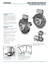
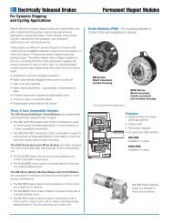
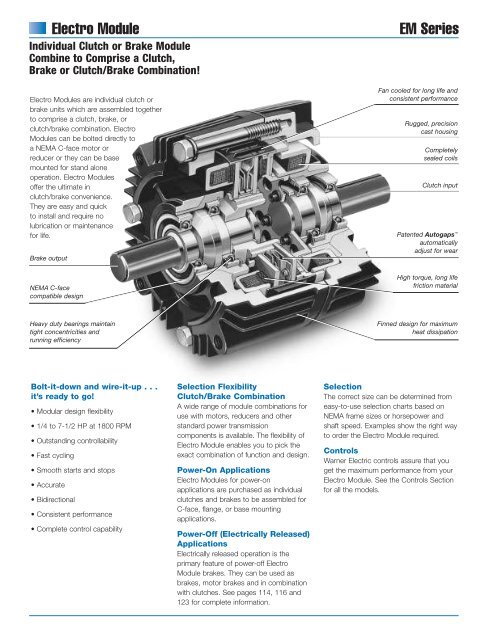
<strong>Electro</strong> <strong>Module</strong>Individual Clutch or Brake <strong>Module</strong>Combine to Comprise a Clutch,Brake or Clutch/Brake Combination!<strong>Electro</strong> <strong>Module</strong>s are individual clutch orbrake units which are assembled togetherto comprise a clutch, brake, orclutch/brake combination. <strong>Electro</strong><strong>Module</strong>s can be bolted directly toa N<strong>EM</strong>A C-face motor orreducer or they can be basemounted for stand aloneoperation. <strong>Electro</strong> <strong>Module</strong>soffer the ultimate inclutch/brake convenience.They are easy and quickto install and require nolubrication or maintenancefor life.Brake output<strong>EM</strong> <strong>Series</strong>Fan cooled for long life andconsistent performanceRugged, precisioncast housingCompletelysealed coilsClutch inputPatented Autogaps automaticallyadjust for wearN<strong>EM</strong>A C-facecompatible designHigh torque, long lifefriction materialHeavy duty bearings maintaintight concentricities andrunning efficiencyFinned design for maximumheat dissipationBolt-it-down and wire-it-up . . .it’s ready to go!• Modular design flexibility• 1/4 to 7-1/2 HP at 1800 RPM• Outstanding controllability• Fast cycling• Smooth starts and stops• Accurate• Bidirectional• Consistent performance• Complete control capabilitySelection FlexibilityClutch/Brake CombinationA wide range of module combinations foruse with motors, reducers and otherstandard power transmissioncomponents is available. The flexibility of<strong>Electro</strong> <strong>Module</strong> enables you to pick theexact combination of function and design.Power-On Applications<strong>Electro</strong> <strong>Module</strong>s for power-onapplications are purchased as individualclutches and brakes to be assembled forC-face, flange, or base mountingapplications.Power-Off (Electrically Released)ApplicationsElectrically released operation is theprimary feature of power-off <strong>Electro</strong><strong>Module</strong> brakes. They can be used asbrakes, motor brakes and in combinationwith clutches. See pages 114, 116 and123 for complete information.SelectionThe correct size can be determined fromeasy-to-use selection charts based onN<strong>EM</strong>A frame sizes or horsepower andshaft speed. Examples show the right wayto order the <strong>Electro</strong> <strong>Module</strong> required.ControlsWarner Electric controls assure that youget the maximum performance from your<strong>Electro</strong> <strong>Module</strong>. See the Controls Sectionfor all the models.
<strong>EM</strong> <strong>Series</strong>Clutch <strong>Module</strong>sClutch Combinations<strong>Electro</strong> <strong>Module</strong>Modular ComponentsClutch/Brake Combinations10 Motor ClutchFan cooled for longlife and consistentperformance.See page 14.30 Input ClutchFan cooled. Sealedcoils. Twin bearingmounted shaftmaintains tightconcentricities.See page 16.40 Output ClutchAutogaps automatically adjust armaturefor wear. Does not have a coil–use in combination with a 10 MotorClutch or 30 Input Clutch module.See page 17.10/40Motor Clutch/Output ClutchUse for clutch only applications. Hashollow bore input for mounting directly toC-face motors. Shaft and C-face onoutput side of unit accommodatesreducer, parallel drive or coupling. Basiccomponents are field, rotor and armature.See page 19.10/20Motor Clutch/BrakeUse for clutch/brake applications. Hollowbore input. Shaft on output side. Basiccomponents are field, rotor, 2 armaturesand power-on magnet. See page 18.10/20-FBCMotor Clutch/Electrically ReleasedBrakeUse for clutch/electrically released brakeapplications. Basic components are field,rotor, 2 armatures and power-off magnet.See page 135.Brake <strong>Module</strong>s20 BrakeBolts directly to C-face components.See page 15.20-FBB Electrically Released BrakeUse for brake alone applications. Has onearmature. See page 134.20-FBC Electrically Released BrakeUse in combination with a 10 MotorClutch or 30 Input Clutch module. Hasdual armatures. See page 135.20MB Motor BrakeDoes not have a shaft. Has end cap.See page 15.20MBFB Electrically ReleasedMotor BrakeAutomatically engages when power goesoff. Requires no power to stop or hold aload. See page 136.30/40Input Clutch/Output ClutchUse for clutch only applications. Featuresdual C-faces and shafts. Unit input fromparallel drive or coupling. Output toreducer. Basic components are field, rotorand armature. See page 21.30/40-BInput Clutch/OutputClutch–Base MountedBase mounting allows the clutch units tobe utilized as a separate drive unit. Attachwith pulleys, sprockets, etc. See page 21.20/30Brake/Input ClutchUse for clutch/brake applications. Featuresdual C-faces and shafts. Input fromparallel drive or coupling. Output toreducer. Basic components are field, rotor,2 armatures and power-on magnet.See page 20.20/30-FBCElectrically Released Brake/InputClutchUse for clutch/electrically released brakeapplications. Basic components are field,rotor, 2 armatures and power-off magnet.See page 122.20/30-BBrake/Input Clutch–Base MountedStand alone units attach with pulleys,sprockets, etc. See page 20.20/30-FBC-BElectrically Released Brake/InputClutch–Base MountedStand alone units attach with pulleys,sprockets, etc. See page 122.
Selection<strong>Electro</strong> <strong>Module</strong><strong>Electro</strong> <strong>Module</strong> clutch or brake units maybe mounted directly to N<strong>EM</strong>A C-facemotors and reducers, or can be basemounted.1. Select Configuration11/15/99a. N<strong>EM</strong>A C-face Mountingpage 183<strong>EM</strong> HP/Shaft Speed ChartBased on the N<strong>EM</strong>A C-face frame sizeof the prime mover, select the correctclutch or brake module size from theFrame Size Selection chart. Size 100houses the components of the size 180in a size 50 frame, while size 215incorporates size 210 components.b. Base Mounting<strong>Electro</strong> <strong>Module</strong> assemblies may bemounted as separate drive units drivenfrom the prime mover by V-belts, chainand sprockets, couplings, timing beltsand other standard power transmissioncomponents.Select the correct size module from theHorsepower vs. Shaft Speed chart bydetermining the motor horsepower andRPM at the module location. Thecorrect size <strong>Electro</strong> <strong>Module</strong> is shown atthe intersection of the HP and operatingspeed.For additional sizing information, refer tothe technical sizing procedure (step 2).<strong>EM</strong> <strong>Series</strong>2. Determine TechnicalRequirementsTechnical considerations for sizing andselection are torque and heat dissipation.Each merits careful consideration,especially heat dissipation as over time,use in excessive temperatureenvironments will have an adverse effecton bearing life and coil wire insulationintegrity.Compare the calculated torquerequirement with the average dynamictorque ratings. Select a unit with adequatetorque. If the unit selected on torque isdifferent than the unit selected based onheat, select the larger size unit.Frame Size SelectionN<strong>EM</strong>AFrame Size56C/48Y182C/143TC184C/145TC213C/182TC215C/184TC213TC/215TC<strong>Electro</strong> <strong>Module</strong>Size<strong>EM</strong>-50*<strong>EM</strong>-100**<strong>EM</strong>-180<strong>EM</strong>-210<strong>EM</strong>-215*For 56C/48Y C-frame motors 3/4 HP andsmaller, the <strong>EM</strong>-100 size may be used whereextended life is desirable.**The <strong>EM</strong>-100 size is recommended for motors1 HP and larger.Horsepower vs. vs. Shaft Shaft Speed SpeedHPSHAFT SPEED AT CLUTCH (IN RPM)100 200 300 400 500 600 700 800 900 1000 1100 1200 1500 1800 2000 2400 3000 36001/4<strong>EM</strong>-501/23/41<strong>EM</strong>-100 or <strong>EM</strong>-1801-1/223<strong>EM</strong>-210 or <strong>EM</strong>-21557-1/2
<strong>EM</strong> <strong>Series</strong><strong>Electro</strong> <strong>Module</strong>a. Heat Dissipation SizingFriction surfaces slip during the initialperiod of engagement and, as a result,heat is generated. The clutch/brakeselected must have a heat dissipationrating greater than the heat generatedby the application. Therefore, in highinertia or high cycle rate applications, itis necessary to check the heatdissipation carefully. Inertia, speed andcycle rate are the required parameters.Heat Dissipation CurvesHeat dissipation requirement iscalculated as follows:E = 1.7 x WR 2 x (N/100) 2 x Fwhere:E = Heat (lb. ft./min.)WR 2 = Total reflected inertia at theclutch/brake shaft. Include theclutch/brake output inertia. (lb.ft. 2 )N = Speed in revolutions per minute.(RPM)F = Cycle rate in cycles per minute(CPM)Compare the calculated heat generatedin the application to the unit ratingsusing the heat dissipation curves. Selectthe appropriate unit that has adequateheat dissipation ability.Heat Dissipation (ft. lbs./min.)Size 50Size 50Size Size 100/180 Size 100/180 100/180Size Size 210/215 Size 210/215 210/215Maximum Maximum Maximum Speed Speed 3600 Speed RPM3600 RPM12000 12000 12000Heat Dissipation (ft. lbs./min.)Heat Dissipation (ft. lbs./min.)10000 10000 100008000 8000 80006000 6000 60004000 4000 40002000 2000 2000250° F250° F 250° F200° F200° F 200° F0 0 00 0 900 0 900 900 1800 1800 1800 2700 2700 2700 3600 3600 3600Heat Dissipation (ft. lbs./min.)Maximum Maximum Maximum Speed Speed 3600 Speed RPM3600 RPM18000 18000 18000Heat Dissipation (ft. lbs./min.)Heat Dissipation (ft. lbs./min.)15000 15000 1500012000 12000 120009000 9000 90006000 6000 60003000 3000 3000250° F250° F 250° F200° F200° F 200° F0 0 00 0 900 0 900 900 1800 1800 1800 2700 2700 2700 3600 3600 3600Heat Dissipation (ft. lbs./min.)Maximum Maximum Maximum Speed Speed 3600 Speed RPM3600 RPM36000 36000 3600030000 30000 3000024000 24000 2400018000 18000 1800012000 12000 120006000 6000 6000250° F250° F 250° F200° F200° F 200° F0 0 00 0 900 0 900 900 1800 1800 1800 2700 2700 2700 3600 3600 3600Speed Speed (RPM) Speed (RPM) (RPM)Speed Speed (RPM) Speed (RPM) (RPM)Speed Speed (RPM) Speed (RPM) (RPM)Heat Dissipation (ft. lbs./min.)Heat Dissipation (ft. lbs./min.)b. Torque SizingFor most applications, the correct sizeclutch/brake can be selected from theHorsepower vs. Shaft Speed chart.Determine the motor horsepower andthe RPM at the clutch/brake. Thecorrect size unit is shown at theintersection of horsepower and shaftspeed.If the static torque requirements areknown, refer to the Specifications Tableto select a unit.For some applications, the torquerequirement is determined by the timeallowed to accelerate and decelerate theload. (This time is generally specified inmilliseconds.) For these applications, itis necessary to determine the torquerequirement based on load inertia andthe time allowed for engagement.The torque requirements are calculatedas follows:T = (WR 2 x N) / (308 x t)where:T = Average Dynamic Torque (lb. ft.)WR 2 = Total reflected inertia at theclutch/brake shaft. Include theclutch/brake output inertia. (lb. ft. 2 )N = Speed in revolutions per minute.(RPM)t = Time allowed for the engagement(sec)C-face Clutch/Power-on Brake Dynamic Torque CurvesSize 50Size 50Maximum Maximum Maximum Speed Speed Speed3600 3600 RPM 3600 RPM Static RPM Static Torque Static Torque 16 Torque lb.ft. 16 lb.ft. 16 lb.ft.161412Dynamic Torque (lb.ft.)Dynamic Torque (lb.ft.)10864161412Dynamic Torque (lb.ft.)1086416141210864100% 100% Current Current 100% Current50% Current 50% Current 50% Current2 2 20 0 00 0 900 0 900 900 1800 1800 1800 2700 2700 2700 3600 3600 3600Speed Speed Difference Speed Difference in Difference RPM in RPMin RPMDynamic Torque (lb.ft.)Size Size 100/180 Size 100/180 100/180 Maximum Maximum Maximum Speed Speed Speed3600 3600 RPM 3600 RPM Static RPM Static Torque Static Torque 30 Torque lb.ft. 30 lb.ft. 30 lb.ft.Dynamic Torque (lb.ft.)32 32 3228 28 2824 24 2420 20 2016 16 16100% 100% Current Current 100% Current12 12 128 8 850% Current 50% Current 50% Current4 4 40 0 00 0 9000900 900 1800 1800 1800 2700 2700 2700 3600 3600 3600Dynamic Torque (lb.ft.)Speed Speed Difference Speed Difference in Difference RPM in RPMin RPMDynamic Torque (lb.ft.)Size Size 210/215 Size 210/215 210/215 Maximum Maximum Maximum Speed Speed Speed3600 3600 RPM 3600 RPM Static RPM Static Torque Static Torque 95 Torque lb.ft. 95 lb.ft. 95 lb.ft.96 96 9684 84 8472 72 7260 60 6048 48 4836 36 36100% 100% Current Current 100% Current24 24 2450% Current 50% Current 50% Current12 12 120 0 00 0 9000900 900 1800 1800 1800 2700 2700 2700 3600 3600 3600Dynamic Torque (lb.ft.)Dynamic Torque (lb.ft.)Speed Speed Difference Speed Difference in Difference RPM in RPMin RPM
<strong>Electro</strong> <strong>Module</strong><strong>EM</strong> <strong>Series</strong>Specifications<strong>EM</strong> Size Static Torque lb. ft. Maximum RPM Voltage D.C.50 16 3600 6, 24, or 90100 30 3600 6, 24, or 90180 30 3600 6, 24, or 90210 95 3600 6, 24, or 90215 95 3600 903. AccessoriesWarner Electric <strong>Electro</strong> <strong>Module</strong>s can befitted with several accessories to extendtheir capacity and ease of mounting.a. Conduit BoxN<strong>EM</strong>A 4 and UL listed, available instandard and washdown versions.4. Select ControlWarner Electric manufactures clutch/brakecontrols to meet several system functionsincluding:• On/Off• Torque adjust• Over excitation• Position loopMany requirements beyond function canimpact control selection. See the ControlsSection on page 141 for completeinformation.a. Mounting BracketsTwo styles of mounting brackets areavailable for simplified installation.The base mount is used with the 20/30and 30/40 configurations. A motormount is also available and providessturdy support for 10/20 and 10/40units and motor.
<strong>EM</strong> <strong>Series</strong><strong>Electro</strong> <strong>Module</strong>Ordering InformationPart NumbersDescription Model No. Voltage DC Part No.10 <strong>EM</strong>-50-10 6 5370-270-020Motor Clutch <strong>EM</strong>-50-10 24 5370-270-030<strong>Module</strong> <strong>EM</strong>-50-10 90 5370-270-015<strong>EM</strong>-100-10 6 5370-270-045<strong>EM</strong>-100-10 24 5370-270-056<strong>EM</strong>-100-10 90 5370-270-046<strong>EM</strong>-180-10 6 5370-270-021<strong>EM</strong>-180-10 24 5370-270-055<strong>EM</strong>-180-10 90 5370-270-017<strong>EM</strong>-210-10 6 5371-270-011<strong>EM</strong>-210-10 24 5371-270-027<strong>EM</strong>-210-10 90 5371-270-00920 <strong>EM</strong>-50-20 6 5370-169-043Brake <strong>EM</strong>-50-20 24 5370-169-045<strong>Module</strong> <strong>EM</strong>-50-20 90 5370-169-042<strong>EM</strong>-100-20 6 5370-169-040<strong>EM</strong>-100-20 24 5370-169-072<strong>EM</strong>-100-20 90 5370-169-041<strong>EM</strong>-180-20 6 5370-169-050<strong>EM</strong>-180-20 24 5370-169-071<strong>EM</strong>-180-20 90 5370-169-051<strong>EM</strong>-210-20 6 5371-169-022<strong>EM</strong>-210-20 24 5371-169-034<strong>EM</strong>-210-20 90 5371-169-023<strong>EM</strong>-215-20 90 5371-169-07620MB <strong>EM</strong>-50-20MB 6 5370-169-047Motor <strong>EM</strong>-50-20MB 24 5370-169-062Brake <strong>EM</strong>-50-20MB 90 5370-169-048<strong>EM</strong>-180-20MB 6 5370-169-053<strong>EM</strong>-180-20MB 24 5370-169-073<strong>EM</strong>-180-20MB 90 5370-169-054<strong>EM</strong>-210-20MB 6 5371-169-025<strong>EM</strong>-210-20MB 24 5371-169-035<strong>EM</strong>-210-20MB 90 5371-169-02630 <strong>EM</strong>-50-30 6 5370-270-019Input Clutch <strong>EM</strong>-50-30 24 5370-270-052<strong>Module</strong> <strong>EM</strong>-50-30 90 5370-270-016<strong>EM</strong>-100-30 6 5370-270-047<strong>EM</strong>-100-30 24 5370-270-054<strong>EM</strong>-100-30 90 5370-270-048<strong>EM</strong>-180-30 6 5370-270-049<strong>EM</strong>-180-30 24 5370-270-053<strong>EM</strong>-180-30 90 5370-270-050<strong>EM</strong>-210-30 6 5371-270-023<strong>EM</strong>-210-30 24 5371-270-026<strong>EM</strong>-210-30 90 5371-270-02440 <strong>EM</strong>-50-40 5370-536-008Output <strong>EM</strong>-100-40 5370-536-007Clutch <strong>EM</strong>-180-40 5370-536-009<strong>Module</strong> <strong>EM</strong>-210-40 5371-536-005AccessoriesDescription <strong>EM</strong> Size Part No.Conduit BoxBase Mount Kitfor 2030, 3040Motor Mount Kitfor 20, 1020, 1040How to OrderExample<strong>EM</strong> seriesAll sizes<strong>EM</strong>-180 20 – 30 90 Volt5370-101-04250/100 5370-101-004180 5370-101-002210/215 5371-101-00150/100 5370-101-010180 5370-101-012210/215 5371-101-012Motor or Reducer MountedSimply combine the size number with the configuration of themodular combination from page 9.Specify voltage and whether 20 brake module is power-on (20)or electrically released (20FBB). See chart for specific partnumbers. See pages 130-133 for electrically released models.Order optional conduit box if desired.Input ClutchBrakeBase MountedSimply combine the size number with the configuration of themodular combination from page 9.SizeSpecify voltage and whether 20 brake module is power-on (20)or electrically released (20FBB). See chart for specific partnumbers. Order optional conduit box if desired.Example<strong>EM</strong>-180 20 – 30 - B 90 VoltBaseInput ClutchBrakeSizeSelect Appropriate Power Supply/Control. See the ControlsSection beginning on page 141.
<strong>Electro</strong> <strong>Module</strong>10 Motor Clutch <strong>Module</strong><strong>EM</strong> <strong>Series</strong>AAEF1/2" NPTBBDDBDA1/2" NPTCElectricalConnectionTypical End ViewCCAll dimensions are nominal, unless otherwise noted.Size A Pilot Dia. B Dia. C D Dia. E Max. F Max. AA BB Min. CC DD Key50 4.500 .625 .813 6.750 .599 1.563 30° 36 45° 3/16 x 3/16100 4.500 .625 .813 6.750 .599 1.563 30° 36 45° 3/16 x 3/16180 4.500 .875 .813 6.750 .599 1.563 30° 36 45° 3/16 x 3/16210 8.500 1.125 .703 9.250 .625 1.313 25° 36 45° 1/4 x 1/4SpecificationsModel Size Voltage DC Static Torque lb. ft. Max. RPM Inertia–WR 2 (lb.ft. 2 ) Weight (lbs) N<strong>EM</strong>A Frame Size50 6, 24, 90 16 3600 .020 3.4 56C/48Y*100 6, 24, 90 30 3600 .046 5.1 56C/48Y**180 6, 24, 90 30 3600 .046 5.1210 6, 24, 90 95 3600 .188 9.1* For 56C/48Y Frame motors 3/4 HP and smaller the <strong>EM</strong>-100 sizemay be used where extended life is desirable.** <strong>EM</strong>-100 size is recommended for motors 1 HP and larger.182C/143TC184C/145TC213C/182TC215C/184TCFor N<strong>EM</strong>A Standard frame sizes, see page 137.
<strong>EM</strong> <strong>Series</strong>ABC ElectricalConnectionD E<strong>Electro</strong> <strong>Module</strong>20 Brake <strong>Module</strong>20MB Brake <strong>Module</strong>AA1/2" NPTBBFDDJIHLGSee Note AKSeeNote BNotes:A. Same overall dimensions apply toMotor Brakes. 20MB <strong>Module</strong> doesnot have an output shaft.B. Clutch armature only applies to <strong>EM</strong>-20.Typical End ViewCCAll dimensions are nominal, unless otherwise noted.Size A B C D E F G H I J K L BB DDMax. Max. Max. Dia. Dia. Keyway Min. Pilot Dia. Dia. AA Min. CC Key3/8-16 UNC-2A 3/16 X50 5.188 3.125 .500 1.000 .156 Equally Spaced 6.688 .625 3/16 x 1.813 4.500 .625 30° 36 45° 3/16 x 3/16(4) on 5.875 D. 1-3/83/8-16 UNC-2A 3/16 X100 5.188 3.125 .500 1.000 .156 Equally Spaced 6.688 .625 3/16 x 1.813 4.500 .625 30° 36 45° 3/16 x 3/16(4) on 5.875 D. 1-3/83/8-16 UNC-2A 3/16 X180 5.266 3.125 .500 1.000 .156 Equally Spaced 6.688 .875 3/16 x 1.891 4.500 .875 30° 36 45° 3/16 x 3/16(4) on 5.875 D. 1-3/81/2-16 UNC-2A 1/4 X210 7.578 4.609 .594 1.500 .313 Equally Spaced 9.344 1.125 1/4 x 2.500 8.500 1.125 25° 36 45° 1/4 x 1/4(4) on 7.250 D. 21/2-16 UNC-2A 1/4 X215 8.078 4.609 .594 1.500 .313 Equally Spaced 9.344 1.375 1/4 x 3.000 8.500 1.375 25° 36 45° 5/16 x 5/16(4) on 7.250 D. 2SpecificationsModel Size Voltage DC Static Torque lb. ft. Max. RPM Armatures Inertia–WR 2 Arm. Hub Shaft Weight (lbs) N<strong>EM</strong>A Frame Size50 6, 24, 90 16 3600 .014 .002 .001 6.6 56C/48Y*100 6, 24, 90 30 3600 .036 .003 .002 8.1 56C/48Y**180 6, 24, 90 30 3600 .036 .003 .002 8.1210 6, 24, 90 95 3600 .162 .021 .017 21.5182C/143TC184C/145TC213C/182TC215C/184TC215 90 95 3600 .162 .021 .019 22 213TC/215TC**** For 56C/48Y Frame motors 3/4 HP and smaller the <strong>EM</strong>-100 sizemay be used where extended life is desirable.** <strong>EM</strong>-100 size is recommended for motors 1 HP and larger.*** For 7-1/2 HP max.For N<strong>EM</strong>A standard frame sizes, see page 137.
<strong>Electro</strong> <strong>Module</strong>30 Input Clutch <strong>Module</strong><strong>EM</strong> <strong>Series</strong>GBAHElectrical ConnectionAA1/2" NPTBBDDDFIECCCTypical End ViewAll dimensions are nominal, unless otherwise noted.Size A B C D E F G I AA BB CC DD`Max. Min. Pilot Dia. Dia. Max. H Dia. Min. Key50 1.000 1.56100 1.000 1.56180 1.000 1.563/16 x3/16 x 1-3/83/16 x3/16 x 1-3/83/16 x3/16 x 1-3/81.813 4.500 .625 4.328 2.266 6.688 30° 36 45° 3/16 x 3/161.813 4.500 .625 4.328 2.266 6.688 30° 36 45° 3/16 x 3/161.891 4.500 .875 4.391 2.266 6.688 30° 36 45° 3/16 x 3/16210 1.500 .312 1/4 x 1/4 2.500 8.500 1.125 5.391 2.438 9.219 25° 36 45° 1/4 x 1/4SpecificationsInertia–WR 2Model Size Voltage DC Static Torque lb. ft. Max. RPM Rotor Shaft Weight (lbs) N<strong>EM</strong>A Frame Size50 6, 24, 90 16 3600 .020 .001 6.4 56C/48Y*100 6, 24, 90 30 3600 .046 .002 8.4 56C/48Y**180 6, 24, 90 30 3600 .046 .002 8.4210 6, 24, 90 95 3600 .188 .017 19.8182C/143TC184C/145TC213C/182TC215C/184TC* For 56C/48Y Frame motors 3/4 HP and smaller the <strong>EM</strong>-100 sizemay be used where extended life is desirable.** <strong>EM</strong>-100 size is recommended for motors 1 HP and larger.For N<strong>EM</strong>A standard frame sizes, see page 137.
<strong>EM</strong> <strong>Series</strong><strong>Electro</strong> <strong>Module</strong>40 Output Clutch <strong>Module</strong>BACAA1/2" NPTBBDDFDHEGCCTypical End ViewAll dimensions are nominal, unless otherwise noted.Size A B C D E F G H AA BB CC DDMax. Max. Dia. Min. Pilot Dia. Dia. Min. Key50 5.188 3.125 .156 6.687100 5.188 3.125 .156 6.687180 5.266 3.125 .313 6.687210 7.578 4.609 .313 9.3443/16 x3/16 x 1-3/83/16 x3/16 x 1-3/83/16 x3/16 x 1-3/81/4 x1/4 x 21.813 4.500 .625 30° 36 45° 3/16 x 3/161.813 4.500 .625 30° 36 45° 3/16 x 3/161.891 4.500 .875 30° 36 45° 3/16 x 3/162.500 8.500 1.125 25° 36 45° 1/4 x 1/4SpecificationsInertia–WR 2Model Size Voltage DC Static Torque lb. ft. Max. RPM Armatures Arm. Hub Shaft Weight (lbs) N<strong>EM</strong>A Frame Size50 6, 24, 90 16 3600 .007 .002 .001 4.9 56C/48Y*100 6, 24, 90 30 3600 .018 .003 .002 5.2 56C/48Y**180 6, 24, 90 30 3600 .018 .003 .002 5.2210 6, 24, 90 95 3600 .181 .021 .017 15.2182C/143TC184C/145TC213C/182TC215C/184TC* For 56C/48Y Frame motors 3/4 HP and smaller the <strong>EM</strong>-100 sizemay be used where extended life is desirable.** <strong>EM</strong>-100 size is recommended for motors 1 HP and larger.For N<strong>EM</strong>A standard frame sizes, see page 137.
<strong>Electro</strong> <strong>Module</strong><strong>EM</strong>-10/20 Clutch/Brake Combination<strong>EM</strong> <strong>Series</strong>BAAICCCD30Input Clutch<strong>Module</strong>D20Brake<strong>Module</strong>DENEED REF.JKL10MotorHClutch<strong>Module</strong>FBGEF20BrakeH<strong>Module</strong>NOMNNote: Mounting base is optional and is ordered separately.Motor Clutch (10) and Output Clutch (20) are ordered separately.All dimensions are nominal, unless otherwise noted.Size A B C D E I J K L M N O N<strong>EM</strong>A Frame Size50 6.750 4.844 1.813 6.750 .625 6.688 3.500 6.844 2.000 6.000 .500 5.000 56C/48Y*100 6.750 4.844 1.813 6.750 .625 6.688 3.500 6.844 2.000 6.000 .500 5.000 56C/48Y**180 6.828 4.844 1.891 6.750 .875 6.688 4.500 7.844 3.000 6.625 .813 5.000210 8.891 5.922 2.500 9.250 1.125 9.688 5.250 9.906 3.375 9.000 .625 7.750182C/143TC184C/145TC213C/182TC215C/184TC* For 56C/48Y Frame motors 3/4 HP and smaller the <strong>EM</strong>-100 sizemay be used where extended life is desirable.** <strong>EM</strong>-100 size is recommended for motors 1 HP and larger.For N<strong>EM</strong>A standard frame sizes, see page 137.Motor Mount (M)F (4) slotsEBFor use with 1020, 1040, 20, 20 FBB and 1020 FBC Combinations.ADCSize A B C D E F Part No.50/100 9.25 8.25 11.00 8.000 3.50 .797 x .406 5370-101-010180 9.25 8.25 11.00 8.000 4.50 .797 x .406 5370-101-012/5370-101-047210/215 11.50 10.50 12.00 9.000 5.25 .750 x .406 5371-101-012/5371-101-025
<strong>EM</strong> <strong>Series</strong><strong>Electro</strong> <strong>Module</strong><strong>EM</strong>-10/40 Motor Clutch/Output Clutch CombinationBAAICCDDD ENEED REF.K30Input Clutch<strong>Module</strong>20Brake<strong>Module</strong>JL10Motor Clutch<strong>Module</strong> HFBGEF40Output Clutch<strong>Module</strong> HNOMNNote: Mounting base is optional and is ordered separately.Motor Clutch (10) and Output Clutch (40) are orderedseparately.All dimensions are nominal, unless otherwise noted.Size A B C D E I J K L M N O N<strong>EM</strong>A Frame Size50 6.750 4.844 1.813 6.750 .625 6.688 3.500 6.844 2.000 6.000 .500 5.000 56C/48Y*100 6.750 4.844 1.813 6.750 .625 6.688 3.500 6.844 2.000 6.000 .500 5.000 56C/48Y**180 6.828 4.844 1.891 6.750 .875 6.688 4.500 7.844 3.000 6.625 .813 5.000210 8.891 5.922 2.500 9.250 1.125 9.688 5.250 9.906 3.375 9.000 .625 7.750182C/143TC184C/145TC213C/182TC215C/184TC* For 56C/48Y Frame motors 3/4 HP and smaller the <strong>EM</strong>-100 sizemay be used where extended life is desirable.** <strong>EM</strong>-100 size is recommended for motors 1 HP and larger.For N<strong>EM</strong>A standard frame sizes, see page 137.Motor Mount (M)F (4) slotsEBFor use with 1020, 1040, 20, 20 FBB and 1020 FBC Combinations.ADCSize A B C D E F Part No.50/100 9.25 8.25 11.00 8.000 3.50 .797 x .406 5370-101-010180 9.25 8.25 11.00 8.000 4.50 .797 x .406 5370-101-012/5370-101-047210/215 11.50 10.50 12.00 9.000 5.25 .750 x .406 5371-101-012/5371-101-025
<strong>Electro</strong> <strong>Module</strong><strong>EM</strong>-20/30 Brake/Input Clutch Combination<strong>EM</strong>-20/30-B Brake/Input Clutch Combination – Base Mounted<strong>EM</strong> <strong>Series</strong>BAICCDDK30Input Clutch<strong>Module</strong>20Brake<strong>Module</strong>JLHFGEFHNOMNNote: Mounting base is optional and is ordered separately.Input Clutch (30) module and Brake <strong>Module</strong> (20) areordered separately.All dimensions are nominal, unless otherwise noted.Size A B C Min. D E F G H I J K L M N O50 5.719 9.516 1.813 .625 5.672 .844 4.000 .344 6.688 3.500 6.844 2.000 6.000 .500 5.000100 5.719 9.516 1.813 .625 5.672 .844 4.000 .344 6.688 3.500 6.844 2.000 6.000 .500 5.000180 5.719 9.656 1.891 .875 5.672 .844 4.000 .344 6.688 4.500 7.844 3.000 6.625 .813 5.000210 7.719 12.969 2.500 1.125 8.203 1.094 6.000 .438 9.688 5.250 9.906 3.375 9.000 .625 7.750Base (B)F (4) SlotsEGAD CBFor use with 2030 and 3040 units.Size A B C D F E G Part No.50/100 6.000 5.000 5.672 4.000 .750 X .406 3.500 2.000 5370-101-004180 6.625 5.000 5.672 4.000 .750 X .406 4.500 3.000 5370-101-002/5370-101-049210/215 9.000 7.750 8.203 6.000 .750 X .531 5.250 3.385 5371-101-001/5371-101-026
<strong>EM</strong> <strong>Series</strong><strong>Electro</strong> <strong>Module</strong><strong>EM</strong>-30/40 Input Clutch/Output Clutch Combination<strong>EM</strong>-30/40 Input Clutch/Output Clutch Combination – Base MountedBAICCDDK30Input Clutch<strong>Module</strong>40OutputClutchLJtHFGEFHNOMNNote: Mounting base is optional and is ordered separately.Input Clutch (30) module and Output Clutch (40) are orderedseparately.All dimensions are nominal, unless otherwise noted.Size A B C Min. D E F G H I J K L M N O50 5.719 9.516 1.813 .625 5.672 .844 4.000 .344 6.688 3.500 6.844 2.000 6.000 .500 5.000100 5.719 9.516 1.813 .625 5.672 .844 4.000 .344 6.688 3.500 6.844 2.000 6.000 .500 5.000180 5.719 9.656 1.891 .875 5.672 .844 4.000 .344 6.688 4.500 7.844 3.000 6.625 .813 5.000210 7.719 12.969 2.500 1.125 8.203 1.094 6.000 .438 9.688 5.250 9.906 3.375 9.000 .625 7.750Base (B)F (4) SlotsEGBFor use with 2030 and 3040 units.Size A B C D F E G Part No.50/100 6.000 5.000 5.672 4.000 .750 X .406 3.500 2.000 5370-101-004AD C180 6.625 5.000 5.672 4.000 .750 X .406 4.500 3.000 5370-101-002/5370-101-049210/215 9.000 7.750 8.203 6.000 .750 X .531 5.250 3.385 5371-101-001/5371-101-026Distribuidor Autorizado e Importador - <strong>Arten</strong> <strong>Freios</strong> e <strong>Embreagens</strong> Ltda.Fone: (11) 5594-8333 • Fax (11) 5589-2422 - arten@arten.com.br • www.arten.com.br