MOOVI 30-50 UL CSA - BFT
MOOVI 30-50 UL CSA - BFT
MOOVI 30-50 UL CSA - BFT

Create successful ePaper yourself
Turn your PDF publications into a flip-book with our unique Google optimized e-Paper software.
D811489_01<br />
3) TECHNICAL SPECIFICATIONS<br />
Power supply: ......................................................... 120Va.c.±10% 60Hz (*)<br />
Absorbed power: ................................................................................ <strong>30</strong>0W<br />
Motor: ............................................................................ 1400 min -1 , 4 poles<br />
Capacitor: ..........................................8µF 4<strong>50</strong>V (2<strong>30</strong>V) :32µF 2<strong>50</strong>V (120V)<br />
Absorption: ................................................................................1.4 A: 2.8 A<br />
Insulation class: ......................................................................................... F<br />
Ventilation intervention temperature: ..................................110°C (winding)<br />
Circuit-breaker intervention temperature: .................. 1<strong>30</strong>°C (self-resetting)<br />
Reduction gear lubrication: .............................................Permanent grease<br />
Max torque: ....................................... <strong>MOOVI</strong>-<strong>30</strong> 85Nm: <strong>MOOVI</strong>-<strong>50</strong> 2<strong>50</strong>Nm<br />
Opening time: ................................................ <strong>MOOVI</strong>-<strong>30</strong> 4s : <strong>MOOVI</strong>-<strong>50</strong> 8s<br />
(Aluminium) bar length: .............. <strong>MOOVI</strong>-<strong>30</strong> 3m max : <strong>MOOVI</strong>-<strong>50</strong> 5m max.<br />
Impact reaction (electric edge): ............................ Stop or stop and reverse<br />
Limiting devices: ................................ Electric, incorporated and adjustable<br />
Manual manoeuvre: ......................................................... Quick key release<br />
No. manoeuvres in 24 hour: .................1200 (<strong>MOOVI</strong>-<strong>30</strong>) :600 (<strong>MOOVI</strong>-<strong>50</strong>)<br />
Working temperature: ...........................................................-10°C ÷ +55°C<br />
Degree of protection: ............................................................................ IP24<br />
Actuator weight (without bar): .............................................356N (~35.6 kg)<br />
Dimensions: ................................................................................... See fig.1<br />
Control unit on request: .........................................................Mod. RIGEL 4<br />
(*) Special power voltages available on request.<br />
4) OPTIONAL ACCESSORIES (Fig.16)<br />
- CBO. Foundation base<br />
- <strong>MOOVI</strong> PRM. Antishearing Kit<br />
- <strong>MOOVI</strong> 1<strong>30</strong>. Kit for Cellula 1<strong>30</strong> fixing post<br />
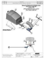
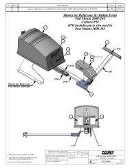
- FAF. Fixed fork for boom rest<br />
- <strong>MOOVI</strong> GA. Movable rod for boom rest (Only for <strong>MOOVI</strong> <strong>50</strong>)<br />
- <strong>MOOVI</strong> GAMA. Movable cushioned rod for boom rest<br />
- SB. Skirt already assembled to the boom<br />
- Safety edge BIR<br />
- <strong>MOOVI</strong> LIGHT. Light kit for booms from 3m to 4.5m<br />
- <strong>MOOVI</strong> LIGHT 1. Light kit for booms from 5m to 6m<br />
- <strong>MOOVI</strong> PCA. Lower or upper boom covering contour<br />
For further information about installation and use of the accessories, make<br />
reference to their respective instruction manuals.<br />
5) FOUNDATION PLATE (Fig.2)<br />
- Prepare a foundation hole suitable for the particular kind of ground.<br />
- Layout several raceways for the electric cables to pass through.<br />
- Position the screws supplied with the CBO mod. base into the 4 fixing<br />
holes with the thread facing upwards. Weld the 4 screw heads to the<br />
base and protect the welds with rust preventer. Position the base so that<br />
it protrudes about 20mm from the floor (fig.2).<br />
- Fill the hole with concrete, checking the position of the base in both<br />
directions by means of a level, and let the cement harden.<br />
6) FITTING OF THE ACTUATOR<br />
WARNING! The barrier must be exclusively used for vehicles to<br />
drive through. Pedestrians must not walk within the operator<br />
manoeuvring area. An appropriate pedestrian passageway must be<br />
provided for. The passageway must be suitably indicated by means of<br />
the warning signs illustrated in Fig.10.<br />
INSTALLATION MANUAL<br />
ENGLISH<br />
- Position the cover closing element (fig.3 ref.10) on the boom, as indicated<br />
in fig. 3. After positioning, drill part 10 and boom using a 2 mm bit. Insert<br />
the screw supplied.<br />
- Fix the boom using the bracket (fig.3 ref.4) and the screws and washers<br />
supplied as standard, then fix the protection cover (fig.3 ref.8) and finally<br />
the screw cover (fig.3 ref.9). Close the protection cover by making the<br />
closing element slide over the boom (fig.3 ref.10).<br />
WARNING! The boom must be positioned so as to have the double<br />
contour facing down (fig.3 ref.11).<br />
- Balance the boom as described in relevant paragraph 7.<br />
6.2) Right-hand fitting<br />
Some internal members need to be moved, with reference to fig. 4 and the<br />
following procedure:<br />
A) Fix the box to the foundation base and lock it in position using M12<br />
nuts.<br />
B) Ensure that the balancing spring is in the opening position (stretched<br />
spring - fig.5).<br />
C) Completely slacken the spring stretcher (fig.4/ref. 2) until the screw (fig.<br />
4/ref.3) anchoring it to the bottom of the box can be removed.<br />
D) Remove the bar locking bracket (fig.4/ref.4) and slacken the screw (fig.<br />
4/ref.5) by means of a CH19 socket spanner until the lever can be rotated<br />
(fig.4/ref.6).<br />
E) Rotate the lever (fig.4/ref.6) by 180° and fasten it into the correct position.<br />
F) Tighten the tie rod (fig. 4/ref.5) blocking the lever (fig.4/ref.6) by means<br />
of a torque wrench set at about 80 N/m.<br />
G) Bring the release key (fig.6) to the manual operation position and manually<br />
rotate the lever (fig.4/ref.6) downwards by 90° (fig.7) so as to bring the<br />
barrier to the right-hand opening position.<br />
H) Lock the spring stretcher (fig.4/ref.2) into position (fig.4/ref.Dx) with the<br />
screw and self-locking nut.<br />
I) Adjust the spring stretcher (fig.4/ref.2) until the spring comes under tension.<br />
L) Refit and partially fix the U bolt (fig.4/ref.4) holding the bar to the actua-tor<br />
in the opening position.<br />
M) The installation of the <strong>MOOVI</strong> PRM antishearing Kit (optional) is easier<br />
when carried out before fitting the boom to the operator.<br />
Make reference to Fig.17 and paragraph 6.3 for correct fitting of the<br />
<strong>MOOVI</strong> PRM Kit, then proceed to fit the boom. Fit the boom in its opening<br />
position (vertical) as indicated in fig.3, ref.7. The operator balancing is<br />
pre-calibrated for the nominal boom in the opening position (balancing<br />
spring stretched).<br />
Position the cover closing element (fig.3 ref.10) on the boom, as indicated<br />
in fig. 3. After positioning, drill part 10 and boom using a 2 mm bit. Insert<br />
the screw supplied.<br />
Fix the boom using the bracket (fig.3 ref.4) and the screws and washers<br />
supplied as standard, then fix the protection cover (fig.3 ref.8) and finally<br />
the screw cover (fig.3 ref.9). Close the protection cover by making the<br />
closing element slide over the boom (fig.3 ref.10).<br />
WARNING! The boom must be positioned so as to have the double<br />
contour facing down (fig.3 ref.11).<br />
N) Carry out bar balancing as described in paragraph 7.<br />
O) Invert the limit switch connections and the motor drive connections insi-de<br />
the control unit (fig.15), with reference to the instructions regar-ding the<br />
existing control unit. Fig.8 shows a diagram highlighting the connections<br />
to be inverted.<br />
WARNING: before opening the door, make sure that the spring has<br />
been unloaded (rod at 43°). The door of the box must face the inside of<br />
the property. When standing in the middle of the passageway, if the box<br />
is on the left the barrier opens to the left, and if the box is on the right the<br />
barrier opens to the right.<br />
The barrier is available with the operator fitted either to the left (looking from<br />
the door side) or to the right.<br />
The actuator is always supplied for left-hand side fitting.<br />
6.1) Left-hand fitting<br />
- Fix the operator to the foundation base and secure it by means of nuts<br />
M12 (fig.4 ref.1). The door of the box must face towards the inside of the<br />
property<br />
- The upper surface of the operator is slightly tilted so as to prevent any<br />
rain water from being trapped there. Therefore use a side surface to check<br />
correct positioning by means of a level (fig.2).<br />
- The installation of the <strong>MOOVI</strong> PRM antishearing Kit (optional) is easier<br />
when carried out before fitting the boom to the operator.<br />
Make reference to Fig.17 and paragraph 6.3 for correct fitting of the<br />
<strong>MOOVI</strong> PRM Kit, then proceed to fit the boom.<br />
- Fit the boom in its opening position (vertical) as indicated in fig.3, ref.7.<br />
The operator balancing is pre-calibrated for the nominal boom in the<br />
opening position (balancing spring stretched).<br />
6.3) Fitting of <strong>MOOVI</strong> PRM antishearing Kit (Fig.17)<br />
1) Remove the rubber plugs.<br />
2) Join two pivots “P” to antishearing plate “L” so as to obtain a single<br />
body.<br />
3) Fix the plate to the box by putting screw M6x20 through the central<br />
threaded hole in the box.<br />
4) Fix rotation lock screw M6x10 through the side threaded hole in the<br />
box.<br />
5) The antishearing plate is to be positioned on the boom opening, the lock<br />
screw through the remaining hole.<br />
6) During subsequent fitting of the cover, the plate must be inserted between<br />
two guide pivots “D” fixed by means of screws C.<br />
Having completed the fitting procedure, check that the antishearing plate<br />
operates correctly. When the barrier is lifted, it must be in the position indicated<br />
in Fig.17, ref.7; when the barrier is being closed, the plate must follow<br />
the boom movement until it reaches the position indicated in Fig.17, ref.8.<br />
6.4) LAMPO/LAMPO-PA blinker fitting (Fig. 18)<br />
Blinker installation is carried using one of the two upper fittings on the<br />
<strong>MOOVI</strong> barrier. It is indispensable to use the SLM2 fixing bracket. It is also<br />
recommended to install the blinker on the side of the barrier opposite to the<br />
boom opening direction.<br />
<strong>MOOVI</strong> <strong>30</strong>-<strong>50</strong> <strong>UL</strong> <strong>CSA</strong> Ver. 01 - 11