istruzioni d'uso e di installazione installation and user's manual - BFT
istruzioni d'uso e di installazione installation and user's manual - BFT
istruzioni d'uso e di installazione installation and user's manual - BFT

Create successful ePaper yourself
Turn your PDF publications into a flip-book with our unique Google optimized e-Paper software.
D811304 ver. 01 15-04-01<br />
I<br />
GB<br />
AUTOMAZIONI A PISTONE PER CANCELLI A BATTENTE<br />
PISTON AUTOMATIONS FOR SWING GATES<br />
8 027908<br />
175687<br />
LUX<br />
ISTRUZIONI D'USO E DI INSTALLAZIONE<br />
INSTALLATION AND USER'S MANUAL<br />
Via Lago <strong>di</strong> Vico, 44<br />
36015 Schio (VI)<br />
Tel.naz. 0445 696511<br />
Tel.int. +39 0445 696533<br />
Fax 0445 696522<br />
Internet: www.bft.it<br />
E-mail: sales@bft.it<br />
LUX Ver. 01 - 1
2 - LUX Ver. 01
MANUALE D’USO<br />
ITALIANO<br />
Nel ringraziarVi per la preferenza accordata a questo prodotto, la <strong>di</strong>tta è<br />
certa che da esso otterrete le prestazioni necessarie al Vostro uso.<br />
Leggete attentamente l’opuscolo “Avvertenze” ed il “Libretto <strong>istruzioni</strong>”<br />
che accompagnano questo prodotto in quanto forniscono importanti in<strong>di</strong>cazioni<br />
riguardanti la sicurezza, l’<strong>installazione</strong>, l’uso e la manutenzione.<br />
Questo prodotto risponde alle norme riconosciute della tecnica e della<br />
<strong>di</strong>sposizioni relative alla sicurezza. Confermiamo che è conforme alle<br />
seguenti norme: CAN/CSA-C22.2 No. 247-92 UL Std. No. 325 (Certificato<br />
100400-1 in data 28 marzo 1994).<br />
2) GENERALITA'<br />
Pistone oleo<strong>di</strong>namico compatto e robusto, <strong>di</strong>sponibile in svariate versioni<br />
a seconda delle esigenze e del campo <strong>di</strong> utilizzo. Ci sono modelli con<br />
blocchi idraulici e modelli senza blocchi (reversibili) che, per mantenere il<br />
blocco , necessitano <strong>di</strong> elettroserratura. Lo sblocco <strong>di</strong> emergenza si attiva<br />
utilizz<strong>and</strong>o l'apposita chiave.<br />
La forza <strong>di</strong> spinta si regola con estrema precisione me<strong>di</strong>ante due valvole bypass<br />
che costituiscono la sicurezza antischiacciamento. Il funzionamento<br />
a fine corsa è regolato elettronicamente nel quadro <strong>di</strong> com<strong>and</strong>o me<strong>di</strong>ante<br />
temporizzatore.<br />
Sono <strong>di</strong>sponibili versioni speciali con rallentamento in fase <strong>di</strong> chiusura<br />
(LUX R) ed il mod. LUX FC ideale per zone innevate o qu<strong>and</strong>o manca la<br />
battuta d'arresto centrale delle ante del cancello (Vedere specifico <strong>manual</strong>e<br />
<strong>istruzioni</strong>).<br />
2) SICUREZZA<br />
L’automazione, se installata ed utilizzata correttamente, sod<strong>di</strong>sfa il grado<br />
<strong>di</strong> sicurezza richiesto.<br />
Tuttavia è opportuno osservare alcune regole <strong>di</strong> comportamento per<br />
evitare inconvenienti accidentali.<br />
• Prima <strong>di</strong> usare l’automazione, leggere attentamente le <strong>istruzioni</strong> d’uso e<br />
conservarle per consultazioni future.<br />
• Tenere bambini, persone e cose fuori dal raggio d’azione dell’automazione,in<br />
particolare durante il funzionamento.<br />
• Non lasciare ra<strong>di</strong>ocoman<strong>di</strong> o altri <strong>di</strong>spositivi <strong>di</strong> com<strong>and</strong>o alla portata dei<br />
bambini onde evitare azionamenti involontari dell’automazione.<br />
• Non contrastare volontariamente il movimento dell’anta.<br />
• Non tentare <strong>di</strong> aprire <strong>manual</strong>mente il cancello se:<br />
Nel modello LUX-LUXL-LUXG-LUXGV non è stata sbloccata<br />
l’elettroserratura con l’apposita chiave.<br />
Nel modello LUXB-LUX2B non è stato azionato lo sblocco con l’apposita<br />
chiave (Fig.1).<br />
• Non mo<strong>di</strong>ficare i componenti dell’automazione.<br />
• In caso <strong>di</strong> malfunzionamento, togliere l’alimentazione, attivare lo sblocco<br />
<strong>di</strong> emergenza per consentire l’accesso e richiedere l’intervento <strong>di</strong> un<br />
tecnico qualificato (installatore).<br />
• Per ogni operazione <strong>di</strong> pulizia esterna, togliere l’alimentazione <strong>di</strong> rete.<br />
• Tenere pulite le ottiche delle fotocellule ed i <strong>di</strong>spositivi <strong>di</strong> segnalazione<br />
luminosa. Controllare che rami ed arbusti non <strong>di</strong>sturbino i <strong>di</strong>spositivi <strong>di</strong><br />
sicurezza (fotocellule).<br />
• Per qualsiasi intervento <strong>di</strong>retto all’automazione, avvalersi <strong>di</strong> personale<br />
qualificato (installatore).<br />
• Annualmente far controllare l’automazione da personale qualificato.<br />
AVVERTENZE<br />
Il buon funzionamento dell’operatore è garantito solo se vengono<br />
rispettate i dati riportati in questo <strong>manual</strong>e. La <strong>di</strong>tta non risponde dei<br />
danni causati dall’inosservanza delle norme <strong>di</strong> <strong>installazione</strong> e delle<br />
in<strong>di</strong>cazioni riportate in questo <strong>manual</strong>e.<br />
Le descrizioni e le illustrazioni del presente <strong>manual</strong>e non sono<br />
impegnative. Lasci<strong>and</strong>o inalterate le caratteristiche essenziali del<br />
prodotto, la Ditta si riserva <strong>di</strong> apportare in qualunque momento le<br />
mo<strong>di</strong>fiche che essa ritiene convenienti per migliorare tecnicamente,<br />
costruttivamente e commercialmente il prodotto, senza impegnarsi<br />
ad aggiornare la presente pubblicazione.<br />
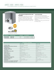
Fig. 1<br />
3) APERTURA MANUALE<br />
Versioni con blocco idraulico (LUXB-LUX2B)<br />
Nei casi <strong>di</strong> emergenza, per esempio in mancanza <strong>di</strong> energia elettrica, per<br />
sbloccare il cancello, infilare la stessa chiave "C" usata per la regolazione<br />
delle valvole by-pass nel perno "P" triangolare situato sotto l'attuatore (fig.<br />
1) e ruotarla in senso antiorario. Il cancello è così apribile <strong>manual</strong>mente<br />
imprimendo una velocità <strong>di</strong> spinta uguale a quella <strong>di</strong> apertura automatica.<br />
Per ripristinare il funzionamento elettrico dell'attuatore, girare la chiave in<br />
senso orario fino al completo bloccaggio del perno "P".<br />
Versione senza blocco idraulico (LUX-LUXL-LUXG-LUXGV)<br />
É sufficiente aprire l'elettroserratura con la relativa chiave e spingere<br />
<strong>manual</strong>mente l'anta.<br />
4) MANUTENZIONE E DEMOLIZIONE<br />
La manutenzione dell’impianto va fatta eseguire regolarmente da<br />
parte <strong>di</strong> personale qualificato. I materiali costituenti l’apparecchiatura e<br />
il suo imballo vanno smaltiti secondo le norme vigenti.<br />
LUX Ver. 01 - 3
ENGLISH<br />
USER’S MANUAL<br />
Thank you for buying this product, our company is sure that you will be more<br />
than satisfied with the product’s performance. The product is supplied with<br />
a “Warnings” leaflet <strong>and</strong> an “Instruction booklet”. These should both be<br />
read carefully as they provide important information about safety, <strong>installation</strong>,<br />
operation <strong>and</strong> maintenance. This product complies with the recognised<br />
technical st<strong>and</strong>ards <strong>and</strong> safety regulations.We declare that this product is<br />
in conformity with the following <strong>di</strong>rectives: CAN/CSA-C22.2 No. 247-92 UL<br />
Std. No. 325 (Certificate: 100400-1 Date Issued: March 28, 1994).<br />
2) GENERAL OUTLINE<br />
A compact, sturdy oleodynamic piston, available in a wide range of models<br />
to fit any need <strong>and</strong> field of operation. It is available in versions both with or<br />
without (reversible) hydraulic lock, that need to be equipped with an electric<br />
lock to hold the gate both closed <strong>and</strong> open.<br />
The emergency release is obtained with the special key provided.<br />
The adjustment of the pushing force is extremely precise <strong>and</strong> is performed<br />
by means of two by-pass valves that act as an antisquash safety. The<br />
operation at the end of the stroke is controlled electronically by a timer in<br />
the control panel.<br />
The LUX series includes special versions with slowdown in the closing<br />
phase (LUX R) while the LUX FC series is especially suited to areas prone<br />
to heavy snowfalls or where the central gate stop cannot be provided (see<br />
specific instruction <strong>manual</strong>).<br />
2) SAFETY<br />
If correctly installed <strong>and</strong> used, this automation device satisfies the required<br />
safety level st<strong>and</strong>ards.<br />
However, it is advisable to observe some practical rules in order to avoid<br />
accidental problems.<br />
• Before using the automation device, carefully read the operation<br />
instructions <strong>and</strong> keep them for future reference.<br />
• Keep children, people <strong>and</strong> things outside the automation working area,<br />
particularly during its operation.<br />
• Keep ra<strong>di</strong>o control or other control devices out of children’s reach, in<br />
order to avoid any unintentional automation activation.<br />
• Do not intentionally oppose the leaf movement.<br />
• Do not attempt to open the gate <strong>manual</strong>ly if:<br />
- In mod. LUX-LUXL-LUXG-LUXGV the electric lock has not been<br />
released by means of the appropriate key.<br />
- In mod. LUXB-LUX2B the release has not been activated by means of<br />
the appropriate key (fig.1).<br />
• Do not mo<strong>di</strong>fy the automation components.<br />
• In case of malfunction, <strong>di</strong>sconnect the power supply, activate the<br />
emergency release to have access to the automation <strong>and</strong> request the<br />
assistance of a qualified technician (installer).<br />
• Before procee<strong>di</strong>ng to any outside cleaning operation, <strong>di</strong>sconnect the<br />
power supply.<br />
• Keep the photocell optical components <strong>and</strong> light signal devices clean.<br />
• Check that the safety devices (photocells) are not obscured by branches<br />
or shrubs.<br />
• For any <strong>di</strong>rect assistance to the automation system, request the help of<br />
a qualified technician (installer).<br />
• Have qualified personnel check the automation system once a year.<br />
WARNINGS<br />
Correct controller operation is only ensured when the data contained<br />
in the present <strong>manual</strong> are observed. The company is not to be held<br />
responsible for any damage resulting from failure to observe the<br />
<strong>installation</strong> st<strong>and</strong>ards <strong>and</strong> the instructions contained in the<br />
present <strong>manual</strong>.<br />
The descriptions <strong>and</strong> illustrations contained in the present <strong>manual</strong><br />
are not bin<strong>di</strong>ng. The Company reserves the right to make any alterations<br />
deemed appropriate for the technical, manufacturing <strong>and</strong> commercial<br />
improvement of the product, while leaving the essential product<br />
features unchanged, at any time <strong>and</strong> without undertaking to update<br />
the present publication.<br />
Fig. 1<br />
3) MANUAL OPENING<br />
Versions with hydraulic lock (LUXB-LUX2B)<br />
In case of emergency, for example during a power cut, the gate can be<br />
released by inserting the same key “C” used to adjust the bypass valve into<br />
the triangular pivot “P” found under the actuator (fig. 1) <strong>and</strong> turning it anticlockwise.<br />
The gate can then be opened <strong>manual</strong>ly following the same<br />
speed as an automatic opening.<br />
To restore the actuator to electrical operation, turn the key clockwise until<br />
pivot “P” is locked.<br />
Versions without hydraulic lock (LUX-LUXL-LUXG-LUXGV)<br />
It is sufficient to open the electric lock with its key <strong>and</strong> move the<br />
leaf <strong>manual</strong>ly.<br />
4) MAINTENANCE AND DEMOLITION<br />
The maintenance of the system should only be carried out by qualified<br />
personnel regularly. The materials making up the set <strong>and</strong> its packing must<br />
be <strong>di</strong>sposed of accor<strong>di</strong>ng to the regulations in force.<br />
4 - LUX Ver. 01
MANUALE PER L’INSTALLAZIONE<br />
ITALIANO<br />
Nel ringraziarVi per la preferenza accordata a questo prodotto, la <strong>di</strong>tta è certa che da<br />
esso otterrete le prestazioni necessarie al Vostro uso.<br />
Leggete attentamente l’opuscolo “Avvertenze” ed il “Libretto <strong>istruzioni</strong>” che accompagnano<br />
questo prodotto in quanto forniscono importanti in<strong>di</strong>cazioni riguardanti la<br />
sicurezza, l’<strong>installazione</strong>, l’uso e la manutenzione. Questo prodotto risponde alle<br />
norme riconosciute della tecnica e della <strong>di</strong>sposizioni relative alla sicurezza. Confermiamo<br />
che è conforme alle seguenti norme: CAN/CSA-C22.2 No. 247-92 UL Std. No. 325<br />
(Certificato 100400-1 in data 28 marzo 1994).<br />
1) SICUREZZA GENERALE<br />
ATTENZIONE! Una <strong>installazione</strong> errata o un uso improprio del prodot-to, può<br />
creare danni a persone, animali o cose.<br />
• Leggete attentamente l’opuscolo ”Avvertenze” ed il ”Libretto istruzio-ni” che<br />
accompagnano questo prodotto, in quanto forniscono Importanti in<strong>di</strong>cazioni<br />
riguardanti la sicurezza, l’<strong>installazione</strong>, l’uso e la manutenzione.<br />
• Smaltire i materiali <strong>di</strong> imballo (plastica, cartone, polistirolo, ecc.) secon-do quanto<br />
previsto dalle norme vigenti. Non lasciare buste <strong>di</strong> nylon e<br />
polistirolo a portata dei bambini.<br />
• Conservare le <strong>istruzioni</strong> per allegarle al fascicolo tecnico e per consul-tazioni future.<br />
• Questo prodotto è stato progettato e costruito esclusivamente per l’utilizzo in<strong>di</strong>cato<br />
in questa documentazione.<br />
Usi non in<strong>di</strong>cati in questa documentazione potrebbero essere fonte <strong>di</strong> danni al<br />
prodotto e fonte <strong>di</strong> pericolo.<br />
• La Ditta declina qualsiasi responsabilità derivante dall’uso improprio o <strong>di</strong>verso da<br />
quello per cui è destinato ed in<strong>di</strong>cato nella presente docu-mentazione.<br />
• Non installare il prodotto in atmosfera esplosiva.<br />
• La Ditta declina qualsiasi responsabilità dall’inosservanza della Buona<br />
Tecnica nella costruzione delle chiusure (porte, cancelli, ecc.), nonché<br />
dalle deformazioni che potrebbero verificarsi durante l’uso.<br />
• Togliere l’alimentazione elettrica, prima <strong>di</strong> qualsiasi intervento sull’im-pianto.<br />
Scollegare anche eventuali batterie tampone se presenti.<br />
• Prevedere sulla rete <strong>di</strong> alimentazione dell’automazione, un interruttore<br />
o un magnetotermico onnipolare con <strong>di</strong>stanza <strong>di</strong> apertura dei contatti uguale o<br />
superiore a 3mm.<br />
• Verificare che a monte della rete <strong>di</strong> alimentazione, vi sia un interruttore<br />
<strong>di</strong>fferenziale con soglia da 0.03A.<br />
• Verificare se l’impianto <strong>di</strong> terra è realizzato correttamente: collegare tutte le parti<br />
metalliche della chiusura (porte, cancelli, ecc.) e tutti i componenti dell’impianto<br />
provvisti <strong>di</strong> morsetto <strong>di</strong> terra.<br />
• Applicare tutti i <strong>di</strong>spositivi <strong>di</strong> sicurezza (fotocellule, coste sensibili, ecc.)<br />
necessari a proteggere l’area da pericoli <strong>di</strong> schiacciamento, convogliamento,<br />
cesoiamento.<br />
• Applicare almeno un <strong>di</strong>spositivo <strong>di</strong> segnalazione luminosa (lampeggiante) in posizione<br />
visibile, fissare alla struttura un cartello <strong>di</strong> Attenzione.<br />
• La Ditta declina ogni responsabilità ai fini della sicurezza e del buon funzionamento<br />
dell’automazione se vengono impiegati componenti <strong>di</strong> altri produttori.<br />
• Usare esclusivamente parti originali per qualsiasi manutenzione o riparazione.<br />
• Non eseguire alcuna mo<strong>di</strong>fica ai componenti dell’automazione se non<br />
espressamente autorizzata dalla Ditta.<br />
• Istruire l’utilizzatore dell’impianto per quanto riguarda i sistemi <strong>di</strong> coman-do<br />
applicati e l’esecuzione dell’apertura <strong>manual</strong>e in caso <strong>di</strong> emergenza.<br />
• Non permettere a persone e bambini <strong>di</strong> sostare nell’area d’azione dell’automazione.<br />
• Non lasciare ra<strong>di</strong>ocoman<strong>di</strong> o altri <strong>di</strong>spositivi <strong>di</strong> com<strong>and</strong>o alla portata dei<br />
bambini onde evitare azionamenti involontari dell’automazione.<br />
• L’utilizzatore deve evitare qualsiasi tentativo <strong>di</strong> intervento o riparazione<br />
dell’automazione e rivolgersi solo a personale qualificato.<br />
• Tutto quello che non è espressamente previsto in queste <strong>istruzioni</strong>, non<br />
è permesso.<br />
INSTALLARE L’APRICANCELLO SOLO QUANDO:<br />
• L’attuatore risulta idoneo per la tipologia costruttiva del cancello e per la classe <strong>di</strong><br />
utilizzo del cancello.<br />
• Tutti i punti <strong>di</strong> schiacciamento evidenti sono protetti o schermati.<br />
• L’apricancello è concepito per essere installato solo su cancelli utilizzati per il<br />
passaggio <strong>di</strong> veicoli. Per i pedoni devono essere previsti accessi separati.<br />
• Il cancello deve essere installato in una posizione tale da garantire una <strong>di</strong>stanza<br />
sufficiente tra il cancello e le strutture a<strong>di</strong>acenti durante l’apertura e la chiusura,<br />
al fine <strong>di</strong> ridurre il rischio <strong>di</strong> intrappolamento.<br />
I cancelli a battente non potranno essere aperti in aree <strong>di</strong> pubblico accesso.<br />
• Il cancello deve essere installato correttamente e deve funzionare<br />
liberamente in entrambe le <strong>di</strong>rezioni prima dell’<strong>installazione</strong> dell’apricancello. Non<br />
serrare eccessivamente la frizione dell’attuatore o la valvola <strong>di</strong> sfiato della pressione<br />
per rime<strong>di</strong>are ad un cancello danneggiato.<br />
IN CASO DI APRICANCELLI CON COMANDO UOMO PRESENTE:<br />
• I coman<strong>di</strong> dell’apricancello devono essere posizionati in modo tale che l’utilizzatore<br />
abbia una visuale completa dell’area del cancello qu<strong>and</strong>o il cancello è in movimento.<br />
• Dovrà essere posizionato vicino ai coman<strong>di</strong> un cartello recante la scritta “AVVER-<br />
TENZA” dalle lettere alte almeno 6,4 mm. e la seguente <strong>di</strong>chiarazione: “ Il cancello<br />
in movimento è in grado <strong>di</strong> causare lesionii o morte - non azionate il cancello qu<strong>and</strong>o<br />
il percorso non è libero”.<br />
• Non dovranno essere utilizzati <strong>di</strong>spositivi <strong>di</strong> chiusura automatici (quali temporizzatori,<br />
rilevatori <strong>di</strong> spira o <strong>di</strong>spositivi similari).<br />
• Non dovrà essere collegato nessun altro <strong>di</strong>spositivo <strong>di</strong> attivazione.<br />
I coman<strong>di</strong> devono essere sufficientemente lontani dal cancello in modo che l’utente non<br />
possa venire a contatto con il cancello qu<strong>and</strong>o utilizza tali coman<strong>di</strong>. I coman<strong>di</strong> previsti<br />
per il resettaggio dell’attuatore dopo due attivazioni successive del <strong>di</strong>spositivo/i contro<br />
l’intrappolamento devono essere posizionati sulla linea visiva del cancello. I coman<strong>di</strong><br />
esterni o facilmente accessibili dovranno essere dotati <strong>di</strong> protezione al fine <strong>di</strong> impe<strong>di</strong>rne<br />
l’utilizzo non autorizzato.<br />
I segnali <strong>di</strong> avvertenza e i cartelli devono essere installati in una posizione visibile<br />
nell’area del cancello.<br />
IN CASO DI ATTUATORI CHE UTILIZZANO UN SENSORE CON RILEVAMENTO<br />
SENZA CONTATTO:<br />
• Leggere le <strong>istruzioni</strong> sul posizionamento dei sensori senza contatto per ogni tipo <strong>di</strong><br />
applicazione.<br />
• Provvedere affinché venga ridotto al minimo il rischio <strong>di</strong> intervento <strong>di</strong> <strong>di</strong>sturbi come<br />
qu<strong>and</strong>o, ad esempio, il veicolo fa scattare il sensore mentre il cancello è ancora in<br />
movimento.<br />
• Posizionare uno o più sensori senza contatto dove esiste il rischio <strong>di</strong> intrappolamento<br />
o ostruzione, ad esempio lungo il perimetro raggiunto dal cancello in movimento.<br />
IN CASO DI ATTUATORI CHE UTILIZZANO UN SENSORE CON RILEVAMENTO<br />
A CONTATTO (COSTA SENSIBILE O EQUIVALENTE):<br />
• Dovranno essere installati uno o più sensori <strong>di</strong> contatto sul punto <strong>di</strong> serraggio <strong>di</strong><br />
cancelli verticali a car<strong>di</strong>ne per passaggio veicolare.<br />
• Dovrà essere installato un sensore con contatto a circuito permanente i cui cablaggi<br />
dovranno essere <strong>di</strong>sposti in modo tale che la comunicazione tra il sensore e<br />
l’apricancello non sia soggetta a danni meccanici.<br />
• Dovrà essere installato un sensore con contatto senza fili quale ad esempio un<br />
sensore che trasmette segnali <strong>di</strong> frequenze ra<strong>di</strong>o (RF) all’apricancello per le<br />
funzioni <strong>di</strong> protezione contro l’intrappolamento nei casi in cui la trasmissione dei<br />
segnali non sia ostacolata o impe<strong>di</strong>ta dalla struttura dell’e<strong>di</strong>ficio, dal paesaggio<br />
naturale o da ostacoli similari. Il sensore con contatto senza fili dovrà funzionare<br />
conformemente alle con<strong>di</strong>zioni per l’utilizzo finale previste.<br />
IMPORTANTI PRESCRIZIONI DI SICUREZZA<br />
ATTENZIONE: al fine <strong>di</strong> ridurre il rischio <strong>di</strong> danni fisici o morte:<br />
TABELLA 1<br />
MOD<br />
LUX<br />
LUX B<br />
LUX 2B<br />
LUX L<br />
LUX G<br />
LUX GV<br />
TIPO DI BLOCCO<br />
ANTA MAX<br />
C ORSA<br />
( mm)<br />
MANOVRE<br />
POMPA TEMPO CORSA<br />
(in)<br />
l/min<br />
UTILE m) (kg)<br />
util<br />
e totale<br />
24 H<br />
gal/min<br />
(ft) (lb)<br />
elettroserratura<br />
1.<br />
2<br />
17<br />
2 300<br />
0,317<br />
6.56 661.4<br />
270<br />
10.62<br />
290<br />
11.41 500<br />
idraulico<br />
chiusura<br />
1.<br />
2<br />
17<br />
2 300<br />
0,317<br />
6.56 661.4<br />
270<br />
10.62<br />
290<br />
11.41<br />
500<br />
idraulico<br />
chius.-aperto<br />
1.<br />
2<br />
17<br />
2 300<br />
0,158<br />
6.56 661.4<br />
270<br />
10.62<br />
290<br />
11.41<br />
500<br />
elettroserratura<br />
0.<br />
6<br />
33<br />
2-4<br />
6.56 300 661.4<br />
0,158<br />
13.12 500 1102.3<br />
270<br />
10.62<br />
290<br />
11.41<br />
350<br />
elettroserratura<br />
0.<br />
6<br />
48<br />
5-2<br />
16.40 300 661.4<br />
0,158<br />
6.56 500 1102.3<br />
390<br />
15.35<br />
410<br />
16.14<br />
250<br />
elettroserratura<br />
1.<br />
2<br />
28<br />
3-5<br />
9.84 300<br />
0,317<br />
16.40 661.4<br />
390<br />
15.35<br />
410<br />
16.14<br />
500<br />
LUX Ver. 01 - 5
ITALIANO<br />
MANUALE PER L’INSTALLAZIONE<br />
• Leggere e osservare tutte le <strong>istruzioni</strong>.<br />
• Non permettere ai bambini <strong>di</strong> utilizzare o giocare con i coman<strong>di</strong> del<br />
cancello. Tenere il telecom<strong>and</strong>o fuori dalla portata dei bambini.<br />
• Tenere lontani oggetti e persone dal cancello. NON E’ PERMESSO<br />
ATTRAVERSARE IL PERCORSO ESEGUITO DAL CANCELLO IN<br />
MOVIMENTO.<br />
• Controllare mensilmente il corretto funzionamento del cancello. Il cancello DEVE<br />
invertire marcia in caso <strong>di</strong> contatto con oggetti rigi<strong>di</strong> e deve fermarsi qu<strong>and</strong>o un<br />
oggetto attiva i sensori senza contatto. Dopo aver regolato la forza o il finecorsa,<br />
ricontrollare l’apricancello.<br />
La mancata regolazione e l’omissione del successivo controllo dell’apricancello<br />
possono aumentare il rischio <strong>di</strong> danni fisici e <strong>di</strong> morte.<br />
• Utilizzare lo sblocco <strong>di</strong> emergenza solo a cancello fermo.<br />
• ESEGUIRE UNA MANUTENZIONE REGOLARE DEL CANCELLO.Leggere il<br />
<strong>manual</strong>e dell’utilizzatore. Eventuali riparazioni alle parti meccaniche del cancello<br />
devono essere eseguite da personale qualificato.<br />
• L’entrata è riservata ai veicoli. Prevedere un’entrata separata per i pedoni.<br />
• Conservare le presenti <strong>istruzioni</strong>.<br />
2) GENERALITA'<br />
Pistone oleo<strong>di</strong>namico compatto e robusto, <strong>di</strong>sponibile in svariate versioni a seconda<br />
delle esigenze e del campo <strong>di</strong> utilizzo. Ci sono modelli con blocchi idraulici e modelli<br />
senza blocchi (reversibili) che, per mantenere il blocco , necessitano <strong>di</strong> elettroserratura.<br />
Lo sblocco <strong>di</strong> emergenza si attiva utilizz<strong>and</strong>o l'apposita chiave.<br />
La forza <strong>di</strong> spinta si regola con estrema precisione me<strong>di</strong>ante due valvole by-pass che<br />
costituiscono la sicurezza antischiacciamento. Il funzionamento a fine corsa è regolato<br />
elettronicamente nel quadro <strong>di</strong> com<strong>and</strong>o me<strong>di</strong>ante temporizzatore.<br />
Sono <strong>di</strong>sponibili versioni speciali con rallentamento in fase <strong>di</strong> chiusura (LUX R) ed il<br />
mod. LUX FC ideale per zone innevate o qu<strong>and</strong>o manca la battuta d'arresto centrale<br />
delle ante del cancello (Vedere specifico <strong>manual</strong>e <strong>istruzioni</strong>).<br />
3) PARTI PRINCIPALI DELL'AUTOMAZIONE (fig. 1)<br />
M) Motore monofase 2 poli protetto da <strong>di</strong>sgiuntore termico<br />
P) Pompa idraulica a lobi<br />
D) Distributore con valvole <strong>di</strong> regolazione<br />
C) Cilindro con pistone<br />
Componenti in dotazione: attacchi al pilastro e al cancello - chiave <strong>di</strong> sblocco e<br />
regolazione bypass - condensatore <strong>di</strong> marcia - <strong>manual</strong>e istruzione<br />
4) DATI TECNICI<br />
Alimentazione: ................................................................... 110Vac ±10% - 60 Hz (*)<br />
Motore: ..................................................................................................... 2800 min -1<br />
Potenza assorbita: ........................................................................................... 250W<br />
Condensatore: ................................................................................................ 6,3 µF<br />
Corrente assorbita: ............................................................................................ 1,4A<br />
Max pressione: ...................................................... 30 bar........................62656 lb/ft 2<br />
Portata pompa: .............................................................................. Vedere Tabella 1<br />
Forza <strong>di</strong> spinta: ..................................................... 3000 N..........................674.42 lbf<br />
Forza <strong>di</strong> trazione: .................................................. 2600 N..........................584.50 lbf<br />
Corsa utile: .................................................................................... Vedere Tabella 1<br />
Reazione all'urto: ............................................................................. frizione idraulica<br />
Manovra <strong>manual</strong>e: ......................................................................... chiave <strong>di</strong> sblocco<br />
Max N° manovre in 24h: ................................................................ Vedere Tabella 1<br />
Protezione termica: ................................................ 160° C................................320°F<br />
Ccon<strong>di</strong>zioni ambientali: ............................. -10° C ÷ 60° C...........................14-140°F<br />
Grado <strong>di</strong> protezione: ......................................................................................... IP 57<br />
Peso operatore: ....................................................... 8,7 kg............................19.18 lb<br />
Dimensioni: ................................................................................................ ve<strong>di</strong> fig. 2<br />
Olio: ............................................................................................................... Idrolux<br />
(*) Tensioni speciali a richiesta<br />
5) INSTALLAZIONE DELL'ATTUATORE<br />
5.1) Verifiche preliminari<br />
Controllare:<br />
• Che la struttura del cancello sia sufficientemente robusta.In ogni caso, l'attuatore<br />
deve spingere l’anta in un punto rinforzato.<br />
• Che le ante si muovano <strong>manual</strong>mente e senza sforzo per tutta la corsa.<br />
• Che siano installate le battute d'arresto delle ante.<br />
• Se il cancello non è <strong>di</strong> nuova <strong>installazione</strong>, controllare lo stato <strong>di</strong> usura <strong>di</strong> tutti i<br />
componenti.<br />
Sistemare o sostituire le parti <strong>di</strong>fettose o usurate.<br />
L’affidabilità e la sicurezza dell’automazione è <strong>di</strong>rettamente influenzato dallo stato della<br />
struttura del cancello.<br />
5.2) Quote <strong>di</strong> <strong>installazione</strong><br />
Le quote <strong>di</strong> <strong>installazione</strong> si ricavano dalla tabella del rispettivo modello (fig.3-4) e<br />
facendo riferimento allo schema <strong>di</strong> fig.5 .<br />
Lo schema <strong>di</strong> fig.5 utilizza le seguenti convenzioni:<br />
P staffa posteriore <strong>di</strong> fissaggio al pilastro<br />
F forcella anteriore <strong>di</strong> fissaggio dell'anta<br />
a-b quote per determinare il punto <strong>di</strong> fissaggio della staffa "P"<br />
C valore dell'interasse <strong>di</strong> fissaggio (ve<strong>di</strong> fig. 2)<br />
D lunghezza del cancello<br />
X <strong>di</strong>stanza dall'asse del cancello allo spigolo del pilastro<br />
Z valore sempre superiore a 45 mm (b - X)<br />
kg peso max dell'anta (Tabella 1)<br />
α° angolo d'apertura dell'anta<br />
5.3) Come interpretare le misure d'<strong>installazione</strong> (fig.3-4)<br />
Dalle tabelle (fig.3-4) è possibile scegliere valori <strong>di</strong> "a" e "b" in funzione dei gra<strong>di</strong> α° <strong>di</strong><br />
apertura che si desiderano ottenere. In ogni tabella, sono evidenziati valori <strong>di</strong> "a" e "b"<br />
ottimali per una apertura <strong>di</strong> α° =90° a velocità costante; in questa con<strong>di</strong>zione, la somma<br />
<strong>di</strong> "a" e "b" è uguale al valore della corsa utile "Cu" (fig.2).<br />
Se si utilizzano valori <strong>di</strong> "a" e "b" troppo <strong>di</strong>versi tra loro, il movimento dell'anta non è<br />
costante e la forza <strong>di</strong> trazione-spinta e la velocità <strong>di</strong> movimento, variano durante la<br />
manovra.<br />
Per valori massimi <strong>di</strong> "a" e "b", è massima la forza sviluppata dal pistone; questa<br />
con<strong>di</strong>zione è utile in particore per cancelli pesanti ed ante lunghe.<br />
ATTENZIONE! Le versioni LUX con stelo dotato <strong>di</strong> occhiello <strong>di</strong> regolazione, consentono<br />
<strong>di</strong> allungare o accorciare lo stelo <strong>di</strong> circa 6mm solo se prima dell'<strong>installazione</strong> lo<br />
si è fissato alle quote in<strong>di</strong>cate in fig.9; ad <strong>installazione</strong> ultimata, questa regolazione,<br />
consente <strong>di</strong> correggere la corsa dello stelo; in fig.10, è in<strong>di</strong>cata l'oscillazione rispetto<br />
all'asse orizzontale, che possono assumere i mod.LUX dotati <strong>di</strong> snodo anteriore e<br />
posteriore.<br />
5.4) Accorgimenti per installazioni particolari<br />
Fig.6 - Necessita realizzare una nicchia per accogliere l'operatore qu<strong>and</strong>o l'anta è<br />
completamente aperta; in fig.6 sono riportate le misure <strong>di</strong> nicchia per i vari modelli LUX.<br />
Fig.7 - Se la quota "a" risulta superiore ai valori riportati nelle tabelle <strong>di</strong> <strong>installazione</strong>,<br />
è necessario spostare il car<strong>di</strong>ne dell'anta, oppure ricavare una nicchia nel pilastro come<br />
in fig.8.<br />
5.5) Ancoraggio degli attacchi al pilastro ed all'anta del cancello.<br />
Fissare l'attacco "P" fig.11 al pilastro con una robusta saldatura; allo stesso modo<br />
saldare all'anta la forcella "F" all'interasse "C" in<strong>di</strong>cato in fig.5 e facendo attenzione che<br />
l'attuatore risulti perfettamente orizzontale (livella "L" fig.11) rispetto al piano <strong>di</strong><br />
movimento del cancello.<br />
• Se il pilastro è in muratura, la piastra "PF" dovrà essere saldata ad una base <strong>di</strong><br />
metallo (mod.PLE) e ancorata in profon<strong>di</strong>tà me<strong>di</strong>ante idonee zanche "Z" saldate sul<br />
retro della stessa (fig. 12).<br />
• Se il pilastro è <strong>di</strong> pietra, la piastra "PF", saldata ad una base <strong>di</strong> metallo (mod.PLE)<br />
può essere fissata con quattro tasselli metallici ad espansione "T" (fig. 13); se il<br />
cancello è gr<strong>and</strong>e, si consiglia <strong>di</strong> saldare la piastra "PF" in una base <strong>di</strong> forma<br />
angolare (fig. 14).<br />
6) BATTUTE D'ARRESTO DELLE ANTE AL SUOLO<br />
Per il corretto funzionamento dell'attuatore è obbligatorio utilizzare delle battute <strong>di</strong><br />
arresto "F" sia in apertura che in chiusura come in<strong>di</strong>cato in fig.15.<br />
Le battute d'arresto delle ante, devono evitare che lo stelo dell'attuatore vada a<br />
finecorsa. In fig.16, sono riportate le quote per verificare la corretta <strong>installazione</strong> con<br />
attuatore in spinta o trazione.Devono essere posizionate in modo da mantenere un<br />
margine <strong>di</strong> corsa dello stelo <strong>di</strong> circa 5-10mm; ciò evita possibili anomalie <strong>di</strong> funzionamento<br />
7) APPLICAZIONE DELL'ELETTROSERRATURA<br />
É necessaria solo nei modelli senza blocco idraulico in chiusura.<br />
L'elettroserratura mod. EBP (fig.17) è costutuita da un elettromagnete a servizio<br />
continuo con aggancio al suolo. In questo <strong>di</strong>spositivo l'eccitazione rimane per tutto il<br />
tempo <strong>di</strong> lavoro del motoriduttore consentendo al dente <strong>di</strong> aggancio "D" <strong>di</strong> arrivare in<br />
battuta <strong>di</strong> chiusura sollevato senza opporre la minima resistenza; tale proprietà<br />
permette <strong>di</strong> <strong>di</strong>minuire il carica <strong>di</strong> spinta in chiusura miglior<strong>and</strong>o la sicurezza<br />
antischiacciamento.<br />
8) MONTAGGIO DEL PRESSACAVO (fig.18)<br />
ATTENZIONE: Fissare la basetta "B" al fondello "F" con le viti "V" in dotazione.<br />
Posizionare il gommino "G" nell'apposita sede nella basetta "B". Infilare il dado "D" nel<br />
cavo <strong>di</strong> alimentazione e poi nella basetta "B", come a <strong>di</strong>segno. Fissare il dado "D" fino<br />
a bloccare il cavo <strong>di</strong> alimentazione.<br />
N.B. La basetta "B" può essere montata sul fondello "F", sia a sinistra che a destra a<br />
seconda della necessità, come a <strong>di</strong>segno.Nella parte inferiore della basetta "B" è<br />
ricavata una spirale per l'eventuale aplicazione <strong>di</strong> una guaina spiralata "GS" in pvc (Ø<br />
= 12).<br />
9) PREDISPOSIZIONE DELL' IMPIANTO ELETTRICO<br />
Pre<strong>di</strong>sporre l’impianto elettrico (fig.19) facendo riferimento alle norme vigenti per gli<br />
impianti elettrici. Tenere nettamente separati i collegamenti <strong>di</strong> alimentazione <strong>di</strong> rete dai<br />
collegamenti <strong>di</strong> servizio (fotocellule, coste sensibili, <strong>di</strong>spositivi <strong>di</strong> com<strong>and</strong>o ecc.).<br />
Attenzione! Per il collegamento alla rete, utilizzare cavo multipolare <strong>di</strong> sezione<br />
minima 3x1.5mm 2 (16AWG) e del tipo previsto dalle normative precedentemente<br />
citate (UL1015).<br />
Realizzare i collegamenti dei <strong>di</strong>spositivi <strong>di</strong> com<strong>and</strong>o e <strong>di</strong> sicurezza in armonia con le<br />
norme per l’impiantistica precedentemente citate. In fig.19 è riportato il numero <strong>di</strong><br />
collegamenti e la sezione per una lunghezza dei cavi <strong>di</strong> alimentazione fino a 328 ft (100<br />
metri); per lunghezze superiori, calcolare la sezione per il carico reale dell’automazione.<br />
Qu<strong>and</strong>o le lunghezze dei collegamenti ausiliari superano i 164 ft (50 metri) o<br />
6 - LUX Ver. 01
MANUALE PER L’INSTALLAZIONE<br />
ITALIANO<br />
passano in zone critiche per i <strong>di</strong>sturbi, è consigliato <strong>di</strong>saccoppiare i <strong>di</strong>spositivi <strong>di</strong><br />
com<strong>and</strong>o e <strong>di</strong> sicurezza con opportuni relè.<br />
Le scatole <strong>di</strong> derivazione dell’alimentazione devono essere pre<strong>di</strong>sposte ad<br />
un’altezza superiore a quella degli operatori, per evitare fuoriuscite <strong>di</strong> olio (Fig.<br />
19).<br />
9.1) Componenti principali per una automazione sono (fig.19):<br />
I Interruttore onnipolare omologato con apertura contati <strong>di</strong> almeno<br />
3mm provvisto <strong>di</strong> protezione contro i sovraccarichi ed i corto circuiti, atto a<br />
sezionare l’automazione dalla rete. Se non presente, prevedere a monte del<br />
l’automazione un interruttore <strong>di</strong>fferenziale omologato <strong>di</strong> adeguata portata e<br />
soglia da 0,03A.<br />
Qr) Quadro com<strong>and</strong>o e ricevente incorporata.<br />
SPL) Scheda <strong>di</strong> preriscaldamento per funzionamento a temperature inferiori ai 5°C<br />
(opzionale).<br />
S) Selettore a chiave.<br />
AL) Lampeggiante con antenna accordata e cavo RG58.<br />
M) Attuatore<br />
E) Elettroserratura.<br />
Fte) Coppia fotocellule esterne (parte emittente)<br />
Fre) Coppia fotocellule esterne (parte ricevente)<br />
Fti) Coppia fotocellule interne con colonnine CF (parte emittente)<br />
Fri) Coppia fotocellule interne con colonnine CF (parte ricevente)<br />
T) Trasmittente 1-2-4 canali<br />
IMPORTANTE: Prima <strong>di</strong> far funzionare elettricamente l'attuatore togliere la vite <strong>di</strong><br />
sfiato "S" (fig.20) posta sotto il blocco snodo e conservarla per eventuale riutilizzo.<br />
Togliere la vite <strong>di</strong> sfiato "S" solo qu<strong>and</strong>o l'attuatore è installato.<br />
10) REGOLAZIONE DELLA FORZA DI SPINTA<br />
E' regolata da due valvole contrad<strong>di</strong>stinte dalla scritta "close" e "open" rispettivamente<br />
per la regolazione della forza <strong>di</strong> spinta in chiusura ed in apertura.<br />
Ruot<strong>and</strong>o le valvole verso il segno"+", aumenta la forza trasmessa; ruot<strong>and</strong>o le valvole<br />
verso il segno"-", <strong>di</strong>minuisce<br />
Per una buona sicurezza antischiacciamento, la forza <strong>di</strong> spinta deve essere <strong>di</strong> poco<br />
superiore a quella necessaria per muovere l'anta sia in chiusura che in apertura; la<br />
forza, misurata in punta all'anta, non deve comunque superare i limiti previsti dalle<br />
norme nazionali vigenti. In nessun caso comunque si devono chiudere completamente<br />
le valvole dei by-pass. L'attuatore non è provvisto <strong>di</strong> finecorsa elettrici. Pertanto i motori<br />
si spengono qu<strong>and</strong>o è terminato il tempo <strong>di</strong> lavoro impostato nella centralina <strong>di</strong><br />
com<strong>and</strong>o. Tale tempo <strong>di</strong> lavoro, deve essere <strong>di</strong> circa 2-3 secon<strong>di</strong> superiore al momento<br />
in cui le ante incontrano le battute d'arresto al suolo.<br />
11) APERTURA MANUALE<br />
11.1) Versioni con blocco idraulico<br />
Nei casi <strong>di</strong> emergenza, per esempio in mancanza <strong>di</strong> energia elettrica, per sbloccare il<br />
cancello, infilare la stessa chiave "C" usata per la regolazione delle valvole by-pass nel<br />
perno "P" triangolare situato sotto l'attuatore (fig. 21) e ruotarla in senso antiorario. Il<br />
cancello è così apribile <strong>manual</strong>mente imprimendo una velocità <strong>di</strong> spinta uguale a quella<br />
<strong>di</strong> apertura automatica.<br />
Per ripristinare il funzionamento elettrico dell'attuatore, girare la chiave in senso orario<br />
fino al completo bloccaggio del perno "P".<br />
11.2) Versione senza blocco idraulico<br />
É sufficiente aprire l'elettroserratura con la relativa chiave e spingere <strong>manual</strong>mente<br />
l'anta.<br />
12) POSIZIONAMENTO COPERTURE<br />
ATTENZIONE: Nei modelli LUX G, può essere necessario aggiungere uno spessore<br />
<strong>di</strong> circa 25mm sotto la forcella "F" (fig.23) per evitare possibili collisioni durante il<br />
movimento.<br />
La copertura "C" <strong>di</strong> tutti i modelli LUX <strong>di</strong>venta destra o sinistra invertendo la posizione<br />
del tappo "T" (fig.24).<br />
La protezione dei BY-pass (fig.25), va messa in posizione e poi incastrata sotto il<br />
copristelo "C".<br />
13) VERIFICA DELL'AUTOMAZIONE<br />
Prima <strong>di</strong> rendere definitivamente operativa l'automazione, controllare scrupolosamente<br />
quanto segue:<br />
• Verificare che tutti i componenti siano fissati saldamente.<br />
• Controllare il corretto funzionamento <strong>di</strong> tutti i <strong>di</strong>spositivi <strong>di</strong> sicurezza (fotocellule,<br />
costa pneumatica, ecc).<br />
• Verificare il com<strong>and</strong>o della manovra <strong>di</strong> emergenza.<br />
• Verificare l'operazione <strong>di</strong> apertura e chiusura con i <strong>di</strong>spositivi <strong>di</strong> com<strong>and</strong>o applicati.<br />
• Verificare la logica elettronica <strong>di</strong> funzionamento normale (o personalizzata) nella<br />
centralina <strong>di</strong> com<strong>and</strong>o.<br />
14) USO DELL'AUTOMAZIONE<br />
Poichè l'automazione può essere com<strong>and</strong>ata a <strong>di</strong>stanza me<strong>di</strong>ante ra<strong>di</strong>ocom<strong>and</strong>o o<br />
pulsante <strong>di</strong> Start, è in<strong>di</strong>spensabile controllare frequentemente la perfetta efficienza <strong>di</strong><br />
tutti i <strong>di</strong>spositivi <strong>di</strong> sicurezza.<br />
Per qualsiasi anomalia <strong>di</strong> funzionamento, intervenire rapidamente avvalendosi <strong>di</strong><br />
personale qualificato.<br />
Si raccom<strong>and</strong>a <strong>di</strong> tenere i bambini a debita <strong>di</strong>stanza dal raggio d'azione dell'automazione.<br />
15) COMANDO<br />
Il com<strong>and</strong>o può essere <strong>di</strong> <strong>di</strong>verso tipo (<strong>manual</strong>e, con ra<strong>di</strong>ocom<strong>and</strong>o, controllo accessi<br />
con badge magnetico, ecc.) secondo le necessità e le caratteristiche dell'<strong>installazione</strong>.<br />
Per i vari sistemi <strong>di</strong> com<strong>and</strong>o, vedere le relative <strong>istruzioni</strong>.<br />
Gli utilizzatori dell'automazione devono essere istruiti al com<strong>and</strong>o e all'uso.<br />
16) MANUTENZIONE<br />
Per qualsiasi manutenzione all'operatore, togliere alimentazione al sistema.<br />
• Verificare perio<strong>di</strong>camente se ci sono per<strong>di</strong>te d'olio.<br />
Per effettuare il rabbocco olio procedere come segue:<br />
a) Avvitare la vite <strong>di</strong> sfiato (fig.20) e smontare l'operatore dal cancello.<br />
b) Far rientrare completamente lo stelo.<br />
c) Mettere l'operatore in posizione verticale e svitare il tappo "O" (fig.18).<br />
d) Rabboccare con olio <strong>di</strong> uguale tipo fino a sommergere il cuscinetto del<br />
motore che si intravede sotto il tappo "O".<br />
e) Chiudere il tappo "O" e rimontare l'operatore nel cancello.<br />
f) Togliere la vite <strong>di</strong> sfiasto.<br />
g) Eseguire 2 manovre complete recuper<strong>and</strong>o l'olio in eccedenza che esce<br />
dallo sfiato.<br />
• Verificare i <strong>di</strong>spositivi <strong>di</strong> sicurezza del cancello e della motorizzazione.<br />
• Per qualsiasi anomalia <strong>di</strong> funzionamento non risolta, togliere alimentazione al<br />
sistema e chiedere l'intervento <strong>di</strong> personale qualificato (installatore).<br />
Nel periodo <strong>di</strong> fuori servizio, attivare lo sblocco <strong>manual</strong>e per consentire<br />
l'apertura e la chiusura <strong>manual</strong>e.<br />
17) INCONVENIENTI E RIMEDI<br />
17.1) Funzionamento <strong>di</strong>fettoso del motoriduttore<br />
• Verificare con apposito strumento la presenza <strong>di</strong> tensione ai capi del motoriduttore<br />
dopo il com<strong>and</strong>o <strong>di</strong> apertura o chiusura.<br />
Se il motore vibra ma non gira, può essere:<br />
• sbagliato il collegamento del filo comune C, (in ogni caso è <strong>di</strong> colore celeste).<br />
• non è collegato il condensatore <strong>di</strong> marcia ai due morsetti <strong>di</strong> marcia.<br />
• se il movimento dell'anta, è contrario a quello che dovrebbe essere, invertire i<br />
collegamenti <strong>di</strong> marcia del motore nella centralina.<br />
ARRESTI ANTE; qu<strong>and</strong>o il tempo <strong>di</strong> lavoro impostato nella centralina, è insufficente,<br />
può succedere che le ante non completino la loro corsa. Alzare legermente il tempo<br />
<strong>di</strong> lavoro nella centralina.<br />
17.2) Funzionamento <strong>di</strong>fettoso degli accessori elettrici<br />
Tutti i <strong>di</strong>spositivi <strong>di</strong> com<strong>and</strong>o e <strong>di</strong> sicurezza, in caso <strong>di</strong> guasto, possono causare<br />
anomalie <strong>di</strong> funzionamento o blocco dell'automazione stessa.<br />
Se la centralina <strong>di</strong> com<strong>and</strong>o è dotata <strong>di</strong> auto<strong>di</strong>agnostica, in<strong>di</strong>viduare il <strong>di</strong>ffetto. In caso<br />
<strong>di</strong> guasto, è opportuno scollegare uno ad uno tutti i <strong>di</strong>spositivi dell'automazione, fino ad<br />
in<strong>di</strong>viduare quello che causa il <strong>di</strong>ffetto. Dopo averlo sostituito o riparato, ripristinare tutti<br />
i <strong>di</strong>spositivi precedentemente scollegati. Per tutti i <strong>di</strong>spositivi installati, fare riferimento<br />
al rispettivo <strong>manual</strong>e istruzione.<br />
ATTENZIONE: L'intervento deve essere eseguito da personale qualificato. Durante<br />
le operazioni <strong>di</strong> manutenzione, la zona operativa del cancello deve essere opportunamente<br />
segnalata e transennata in modo da evitare pericoli per persone, animali, cose.<br />
AVVERTENZE:<br />
Il buon funzionamento dell'operatore è garantito solo se vengono rispettate i dati<br />
riportati in questo <strong>manual</strong>e.<br />
La <strong>di</strong>tta non risponde dei danni causati dall'innosservanza delle norme <strong>di</strong> sicurezza, <strong>di</strong><br />
<strong>installazione</strong>, <strong>di</strong> buona tecnica, delle in<strong>di</strong>cazioni riportate in questo <strong>manual</strong>e.<br />
18) DEMOLIZIONE<br />
Attenzione: Avvalersi esclusivamente <strong>di</strong> personale qualificato.<br />
L’eliminazione dei materiali va fatta rispett<strong>and</strong>o le norme vigenti.<br />
Nel caso <strong>di</strong> demolizione dell’automazione non esistono particolari pericoli<br />
o rischi derivanti dall’automazione stessa.<br />
È opportuno, in caso <strong>di</strong> recupero dei materiali, che vengano separati per<br />
tipologia (parti elettriche - rame - alluminio - plastica - ecc.).<br />
19) SMANTELLAMENTO<br />
Attenzione: Avvalersi esclusivamente <strong>di</strong> personale qualificato.<br />
Nel caso l’automazione venga smontata per essere poi rimontata in altro<br />
sito bisogna:<br />
• Togliere l’alimentazione e scollegare tutto l’impianto elettrico esterno.<br />
• Nel caso alcuni componenti non possano essere rimossi o risultino danneggiati,<br />
provvedere alla loro sostituzione.<br />
Le descrizioni e le illustrazioni del presente <strong>manual</strong>e non sono impegnative.<br />
Lasci<strong>and</strong>o inalterate le caratteristiche essenziali del prodotto, la Ditta si riserva<br />
<strong>di</strong> apportare in qualunque momento le mo<strong>di</strong>fiche che essa ritiene convenienti<br />
per migliorare tecnicamente,<br />
costruttivamente e commercialmente il prodotto, senza impegnarsi ad aggiornare<br />
la presente pubblicazione.<br />
LUX Ver. 01 - 7
ENGLISH<br />
INSTALLATION MANUAL<br />
Thank you for buying this product, our company is sure that you will be more than<br />
satisfied with the product’s performance. The product is supplied with a “Warnings”<br />
leaflet <strong>and</strong> an “Instruction booklet”. These should both be read carefully as they<br />
provide important information about safety, <strong>installation</strong>, operation <strong>and</strong> maintenance.<br />
This product complies with the recognised technical st<strong>and</strong>ards <strong>and</strong> safety<br />
regulations.We declare that this product is in conformity with the following <strong>di</strong>rectives:<br />
CAN/CSA-C22.2 No. 247-92 UL Std. No. 325 (Certificate: 100400-1 Date Issued:<br />
March 28, 1994).<br />
1) GENERAL SAFETY<br />
WARNING! An incorrect <strong>installation</strong> or improper use of the product can<br />
cause damage to persons, animals or things.<br />
• The “Warnings” leaflet <strong>and</strong> “Instruction booklet” supplied with this product<br />
should be read carefully as they provide important information about safety,<br />
<strong>installation</strong>, use <strong>and</strong> maintenance.<br />
• Scrap packing materials (plastic, cardboard, polystyrene etc) accor<strong>di</strong>ng to the<br />
provisions set out by current st<strong>and</strong>ards. Keep nylon or polystyrene bags out of<br />
children’s reach.<br />
• Keep the instructions together with the technical brochure for future reference.<br />
• This product was exclusively designed <strong>and</strong> manufactured for the use specified in<br />
the present documentation. Any other use not specified in this documentation<br />
could damage the product <strong>and</strong> be dangerous.<br />
• The Company declines all responsibility for any consequences resulting from<br />
improper use of the product, or use which is <strong>di</strong>fferent from that expected <strong>and</strong><br />
specified in the present documentation.<br />
• Do not install the product in explosive atmosphere.<br />
• The Company declines all responsibility for any consequences resulting from<br />
failure to observe Good Technical Practice when constructing closing structures<br />
(door, gates etc.), as well as from any deformation which might occur during use.<br />
• Disconnect the electrical power supply before carrying out any work on the<br />
<strong>installation</strong>. Also <strong>di</strong>sconnect any buffer batteries, if fitted.<br />
• Fit an omnipolar or magnetothermal switch on the mains power supply, having a<br />
contact opening <strong>di</strong>stance equal to or greater than 3mm.<br />
• Check that a <strong>di</strong>fferential switch with a 0.03A threshold is fitted just before the power<br />
supply mains.<br />
• Check that earthing is carried out correctly: connect all metal parts for closure<br />
(doors, gates etc.) <strong>and</strong> all system components provided with an earth terminal.<br />
• Fit all the safety devices (photocells, electric edges etc.) which are needed to<br />
protect the area from any danger caused by squashing, conveying <strong>and</strong> shearing.<br />
• Position at least one luminous signal in<strong>di</strong>cation device (blinker) where it can be<br />
easily seen, <strong>and</strong> fix a Warning sign to the structure.<br />
• The Company declines all responsibility with respect to the automation<br />
safety <strong>and</strong> correct operation when other manufacturers’ components are<br />
used.<br />
• Only use original parts for any maintenance or repair operation.<br />
• Do not mo<strong>di</strong>fy the automation components, unless explicitly authorised by the<br />
company.<br />
• Instruct the product user about the control systems provided <strong>and</strong> the <strong>manual</strong><br />
opening operation in case of emergency.<br />
• Do not allow persons or children to remain in the automation operation area.<br />
• Keep ra<strong>di</strong>o control or other control devices out of children’s reach, in order to avoid<br />
unintentional automation activation.<br />
• The user must avoid any attempt to carry out work or repair on the automation<br />
system, <strong>and</strong> always request the assistance of qualified personnel.<br />
• Anything which is not expressly provided for in the present instructions, is not<br />
allowed.<br />
INSTALL THE GATE OPERATOR ONLY WHEN:<br />
• The operator is appropriate for the construction of the gate <strong>and</strong> the usage Class<br />
of the gate,<br />
• All exposed pinch points are eliminated or guarded,<br />
• The operator is intended for <strong>installation</strong> only on gates used for vehicles. Pedestrians<br />
must supplied with a separate access opening,<br />
• The gate must be installed in a location so that enough clearance is supplied<br />
between the gate <strong>and</strong> adjacent structures when opening <strong>and</strong> closing to reduce the<br />
risk of entrapment. Swinging gates shall not open into public access areas,<br />
• The gate must be properly installed <strong>and</strong> work freely in both <strong>di</strong>rections prior to the<br />
<strong>installation</strong> of the gate operator. Do not over-tighten the operator clutch or presure<br />
relief valve to compensate for a damaged gate.<br />
FOR GATE OPENERS WITH HOLD-TO-RUN CONTROL:<br />
• The gate operator controls must be placed so that the user has full view of the gate<br />
area when the gate is moving,<br />
• A sign with the message “WARNING” must be positioned near the controls. The<br />
characters for the writing should be at least 6.4 mm high. The following statement<br />
should also be in<strong>di</strong>cated: “Moving Gate Has the Potential of Inflicting Injury or<br />
Death - Do Not Start Gate Unless Path is Clear”.<br />
• An automatic closing device (such as a timer, loop sensor, or similare device) shall<br />
not be employed<br />
• No other activation device shall be connected.<br />
Controls must be far enough from the gate so that the user is prevented from coming<br />
in contact with the gate while operating the controls. controls intended to be used to<br />
reset an operator after 2 sequential activations of the entrapment protection device<br />
or devices must be located in the line-of-sight of the gate. Outdoor or easly accesible<br />
controls shall have a security feature to prevent unauthorized use.<br />
All warnings signs <strong>and</strong> placards must be installed where visible in the area of the gate.<br />
FOR GATE OPENERS PROVIDED WITH SENSOR FOR CONTACT-FREE<br />
DETECTION:<br />
• See instructions on the placement of non contact sensor for each type of<br />
application,<br />
• Care shall be exercised to reduce the risk of nuisance tripping, such as when a<br />
vheicle, trips the sensor while the gate is still moving, <strong>and</strong><br />
• One or more non-contact sensor shall be located where the risk of entrapment or<br />
obstruction exist, such as the perimeter reachable by a moving gate.<br />
FOR GATE OPENERS PROVIDED WITH CONTACT DETECTION (RUBBER<br />
EDGE OR SIMILAR):<br />
• On or more contact sensor shall be located at the pinch point of a vehicular vertical<br />
pivot gate.<br />
• A hardwired contact sensor shall be located <strong>and</strong> its wiring arranged so that the<br />
communication between the sensor <strong>and</strong> the gate operator is not subjected to<br />
mechanical damage.<br />
• A wireless contact sensor such as one that transimts ra<strong>di</strong>o frequency (RF) signals<br />
the gate operator for entrapment protection functions shall be located where the<br />
transimission of the signals are not obscrtucted or impeded y buil<strong>di</strong>ng structure,<br />
natural l<strong>and</strong>scaping or similar obstruction. A wireless contact sensor shall function<br />
under the intended end-use con<strong>di</strong>tions.<br />
IMPORTANT SAFETY INSTRUCTIONS<br />
WARNINGS: to reduce the risk of injury or death:<br />
• Read <strong>and</strong> follow all instructions.<br />
• Never let children operate or play with gate control. Keep the remote control away<br />
TABLE 1<br />
MOD<br />
LUX<br />
LUX B<br />
LUX 2B<br />
LUX L<br />
LUX G<br />
LUX GV<br />
PUMP<br />
WORKING<br />
TIME (S)<br />
MAX WING<br />
STROKE<br />
MANOEUVRES<br />
TYPE OF BLOCK<br />
l/min<br />
( m) (kg)<br />
gal/min<br />
(ft) (lb)<br />
working<br />
tot<br />
24 H<br />
electric<br />
lock<br />
1.2<br />
17<br />
2 300<br />
0,317<br />
6.56 661.4<br />
270<br />
10.62"<br />
290<br />
11.41"<br />
500<br />
hydraulic<br />
closing<br />
hydraulic<br />
clos. - open<br />
1.2<br />
17<br />
2 300<br />
0,317<br />
6.56 661.4<br />
1.2<br />
17<br />
2 300<br />
0,158<br />
6.56 661.4<br />
270<br />
270<br />
290<br />
10.62"<br />
290<br />
10.62"<br />
11.41"<br />
11.41"<br />
500<br />
500<br />
electric<br />
lock<br />
0.6<br />
33<br />
2-4 6.56 300 661.4<br />
0,158<br />
13.12 500 1102.3<br />
270<br />
290<br />
10.62" 11.41"<br />
350<br />
electric<br />
lock<br />
0.6<br />
48<br />
5-2 16.40 300 661.4<br />
0,158<br />
6.56 500 1102.3<br />
390<br />
15.35"<br />
410<br />
16.14"<br />
250<br />
electric<br />
lock<br />
1.2<br />
28<br />
3-5 9.84 300<br />
0,317<br />
16.40 661.4<br />
390<br />
410<br />
15.35" 16.14"<br />
500<br />
(mm)<br />
(in)<br />
8 - LUX Ver. 01
INSTALLATION MANUAL<br />
ENGLISH<br />
from children.<br />
• Always keep people <strong>and</strong> objects away from the gate. NO ONE SHOULD<br />
CROSS THE PATH OF THE MOVING GATE.<br />
• Test the gate operator montly. The gate MUST reverse on contact with a rigid<br />
object activates the non-contact sensor. After adjusting the force or the limit of<br />
travel, reset the gate operator. Failure to adjust <strong>and</strong> retest the gate operator<br />
properly can increase the risk of injury or death.<br />
• Use the emergency realease only when the gate is not moving.<br />
• KEEP GATES PROPERLY MAINTAINED. Read the owners <strong>manual</strong>. Have a<br />
qualified service person make repairs to gate hardware.<br />
• The entrance is for veichles only. Pedestrians must use separate entrance.<br />
• Save these instructions.<br />
2) GENERAL OUTLINE<br />
A compact, sturdy oleodynamic piston, available in a wide range of models to fit any<br />
need <strong>and</strong> field of operation. It is available in versions both with or without (reversible)<br />
hydraulic lock, that need to be equipped with an electric lock to hold the gate both<br />
closed <strong>and</strong> open.<br />
The emergency release is obtained with the special key provided.<br />
The adjustment of the pushing force is extremely precise <strong>and</strong> is performed by means<br />
of two by-pass valves that act as an antisquash safety. The operation at the end of<br />
the stroke is controlled electronically by a timer in the control panel.<br />
The LUX series includes special versions with slowdown in the closing phase (LUX<br />
R) while the LUX FC series is especially suited to areas prone to heavy snowfalls or<br />
where the central gate stop cannot be provided (see specific instruction <strong>manual</strong>).<br />
3) THE MAIN PARTS IN THE AUTOMATION (fig. 1)<br />
M) Single phase 2 pole motor protected by thermal circuit breaker<br />
P) Hydraulic lobe pump<br />
D) Fluid <strong>di</strong>stributor with adjustment valves<br />
C) Cylinder with piston<br />
St<strong>and</strong>ard components:<br />
• gate post <strong>and</strong> gate brackets - release key <strong>and</strong> bypass adjustment<br />
• drive capacitor - instruction booklet.<br />
4) TECHNICAL SPECIFICATIONS<br />
Power supply: ................................................................. 110Vac ±10% - 60 Hz (*)<br />
Motor: .................................................................................................... 2800 min -1<br />
Power absorption: ......................................................................................... 250W<br />
Capacitor: .................................................................................................... 6.3 µF<br />
Current absorption ......................................................................................... :1.4A<br />
Max. pressure: .................................................... 30 bar........................62656 lb/ft 2<br />
Pump delivery: .................................................................................... See Table 1<br />
Pushing force: ................................................... 3000 N..........................674.42 lbf<br />
Pulling force: ...................................................... 2600 N..........................584.50 lbf<br />
Working stroke: .................................................................................. See Table 1<br />
Impact reaction: ............................................................................. hydraulic clutch<br />
Manual manoeuvres: ...................................................................... by release key<br />
Max. no. manoeuvres in 24: ................................................................ See table 1<br />
Thermal protection: ............................................. 160° C................................320°F<br />
Ambient temperature: ............................. -10° C ÷ 60° C...........................14-140°F<br />
Protection: ..................................................................................................... IP 57<br />
Controller weight: .................................................. 8,7 kg............................19.18 lb<br />
Dimensions ............................................................................................. :see fig. 2<br />
Circuit oiI .................................................................................................... :idrolux<br />
(*) Special voltages on request<br />
5) INSTALLATION OF THE ACTUATOR<br />
5.1) Preliminary checks<br />
Check:<br />
• that the structure of the gate is rigid <strong>and</strong> strong enough. In any case, the actuator<br />
must push against a reinforced point in the leaf<br />
• that the leaves move <strong>manual</strong>ly without excessive effort for the whole of their stroke<br />
• that the door stops are mounted on the leaves<br />
• If the gate being installed is not new, check whether its components are<br />
worn.<br />
Repair or replace any worn or damaged parts.<br />
Automation reliability <strong>and</strong> safety are <strong>di</strong>rectly influenced by the con<strong>di</strong>tion of the gate’s<br />
structure.<br />
5.2) Installation values<br />
The values to be known for <strong>installation</strong> can be found in the table related to the model being<br />
installed (fig. 3-4), with reference also to the <strong>di</strong>agram in fig. 5.<br />
The <strong>di</strong>agram in fig. 5 uses the following legend:<br />
P Gate-post fastening rear bracket<br />
F Leaf fastening front fork<br />
a-b “P” bracket <strong>installation</strong> values<br />
C Distance between fixing points (see fig. 2)<br />
D Gate length<br />
X Distance from gate axis to the edge of the post<br />
Z always over 45 mm (b - X)<br />
kg max. weight of leaf (Table 1)<br />
α° leaf opening in degrees<br />
5.3) How to read the <strong>installation</strong> <strong>di</strong>mensions (fig- 3-4)<br />
From the tables (fig. 3-4), select “a” <strong>and</strong> “b” accor<strong>di</strong>ng to the angle in degrees α° that<br />
the gate has to open. Each table shows the ideal value for “a” <strong>and</strong> “b” for an opening<br />
of α° = 90° at constant speed.<br />
In this con<strong>di</strong>tion, the sum of “a” plus “b” gives the value of the working stroke “Cu” (fig.<br />
2).<br />
If there is too large a <strong>di</strong>fference between “a” <strong>and</strong> “b”, the leaf will not travel smoothly<br />
<strong>and</strong> the pushing or pulling force will fluctuate during its stroke.<br />
When “a” <strong>and</strong> “b” are at their maximum, the piston develops the maximum force. This<br />
con<strong>di</strong>tion is particularly useful for heavy gates or gates with very long leaves.<br />
WARNING! The LUX models having a rod with adjustment ball joint enable the rod<br />
to be lengthened or shortened by about 6 mm., but only if it is set in the position shown<br />
in fig. 9 before being installed. When installed, this adjustment will allow for correcting<br />
the stroke of the rod. Fig. 10 shows the oscillation to which the LUX models with front<br />
<strong>and</strong> rear joint are subject with respect to the horizontal axis.<br />
5.4) Off-st<strong>and</strong>ard <strong>installation</strong>s<br />
Fig. 6 - need for a recess to house the controller when the leaf is completely<br />
opened;Fig. 6 gives the size of the recess for the <strong>di</strong>fferent LUX models.<br />
Fig. 7 - if the “a” value is higher than the values listed in the <strong>installation</strong> tables, the leaf’s<br />
hinge pivot should be shifted, or a recess be made in the gate-post (fig. 8).<br />
5.5) Mounting the brackets to the gate-post <strong>and</strong> to the gate-leaf.<br />
Fix the bracket “P” (fig. 10) to the gate-post with a good wel<strong>di</strong>ng.<br />
The fork “F” should be welded in the same way to the gate leaf along the <strong>di</strong>stance “C”<br />
as shown in fig. 5, taking care that the actuator is perfectly horizontal (level “L” fig. 10)<br />
to the line of travel of the gate.<br />
• If the gate-post is in brick, the plate “PF” must be welded to a metal base (mod.<br />
PLE) <strong>and</strong> set soundly into the post using adequately sized cramps “Z” welded to<br />
the back of the plate (fig. 12).<br />
• If the gate-post is in stone, the plate “PF” welded to a metal base (mod. PLE) can<br />
be fixed with four metal expansion plugs “T” (fig. 13). If a larger gate is being<br />
installed it would be better to weld the plate “PF” to an angular base (fig. 14).<br />
6) GROUND GATE STOPS<br />
For the controller to operate correctly the gate stops “F” must be used both in opening<br />
<strong>and</strong> closing, as shown in fig. 15.<br />
The gate stops should prevent the rod of the actuator from reaching its end of stroke<br />
. Fig. 16 gives the values which ensure a perfect <strong>installation</strong> when the actuator is<br />
performing the pushing or pulling function. They must be placed so that about a 5-10<br />
mm margin of travel is maintained in the rod. This margin prevents any malfunctions.<br />
7) FITTING THE ELECTRIC LOCK<br />
This is only necessary on models without a hydraulic lock at closing end of<br />
stroke.<br />
The electric lock mod. EBP (fig. 17) consists of a continuous electromagnet with<br />
ground catch. As long as the gearmotor is operating, this device features a non-stop<br />
excitation <strong>and</strong> maintains the bolt “D” lifted until it reaches the closing end of stroke<br />
without creating any friction. This characteristic enables the pushing force to be<br />
reduced in closing which will improve the antisquash safety level.<br />
7) MOUNTING THE CABLE-CLAMP (fig. 18)<br />
WARNING! Fix the board “B” to the base “F” with the screws “V” provided. Place the<br />
rubber “G” in its seat in the board “B”. Slide the nut “D” onto the power cable <strong>and</strong> pass<br />
the cable over board “B” as shown in the picture Tighten nut “D” until the power cable<br />
is clamped.<br />
N.B. The board “B” can be fitted onto both the right <strong>and</strong> left of the base “F”, as required<br />
(see picture).<br />
The bottom of board “B” has a spiralled recess to eventually receive a spiralled sheath<br />
“GS” in PVC (Ø = 12).<br />
9) THE ELECTRICAL PLANT SET-UP<br />
Set up the electrical <strong>installation</strong> as shown in fig.19, making reference to the current<br />
st<strong>and</strong>ards for electrical <strong>installation</strong>s. The mains power supply connections must be<br />
kept totally separate from the service connections (photocells, electric edges, control<br />
devices etc.).<br />
Warning! For connection to the mains, use a multipolar cable having minimum<br />
3x1.5mm 2 (16AWG) cross section <strong>and</strong> complying with the previously mentioned<br />
regulations (UL1015).<br />
Connect the control <strong>and</strong> safety devices in compliance with the previously<br />
mentioned electrical <strong>installation</strong> st<strong>and</strong>ards. Fig.16 shows the number of connections<br />
<strong>and</strong> the cross section for power supply cables having a length of approximately 328<br />
ft (100 metres); in case of longer cables, calculate the cross section for the true<br />
automation load. When the auxiliary connections exceed 164 ft (50-metre) lengths or<br />
LUX Ver. 01 - 9
ENGLISH<br />
INSTALLATION MANUAL<br />
go through critical <strong>di</strong>sturbance areas, it is recommended to decouple the control <strong>and</strong><br />
safety devices by means of suitable relays.<br />
The connector blocks for the power supply must be placed at a height greater<br />
than that of the actuators so as to avoid oil leakages (Fig. 19).<br />
9.1) Automation main components (fig. 19)<br />
I) Type approved omnipolar switch with 3 mm min. contact opening.<br />
provided with overload <strong>and</strong> short-circuit protection, used to break the<br />
automation connection from the mains. If not present, provide the<br />
automation with a type approved <strong>di</strong>fferential switch with adequate<br />
capacity <strong>and</strong> a 0.03 A threshold.<br />
Qr) Control unit with built-in receiver<br />
SPL) Pre-heating board for operation at temperatures below 5° C (optional)<br />
S) Key selector<br />
AL) Blinker tuned in with antenna <strong>and</strong> RG58 cable<br />
M) Actuator<br />
Fte) Pair of outside photocells (transmitters)<br />
Fre) Pair of outside photocells (receivers)<br />
Fti) Pair of inside photocells with CF column (transmitters)<br />
Fri) Pair of inside photocells with CF column (receivers)<br />
T) 1-2-4 channel transmitter<br />
IMPORTANT: Before operating the actuator electrically, unscrew the bleeder<br />
screw “S” (fig. 20)found under the joint block <strong>and</strong> keep it for future uses. Remove<br />
the bleeder screw “S” only after having installed the actuator.<br />
10) ADJUSTING THE PUSHING FORCE<br />
The adjustment is made by two valves marked “close” <strong>and</strong> “open” which control the<br />
pushing force during closing <strong>and</strong> opening respectively.<br />
By turning the valves towards “+”, the force is increased, while by turning them<br />
towards “-” it is reduced.<br />
To ensure an adequate antisquash safety, the pushing force must be adjusted to just<br />
over the push needed to move the leaf, both in closing <strong>and</strong> opening. In any event, the<br />
pushing force at the end of the leaf, must not exceed the limits prescribed by current<br />
national regulations. For no reason should the adjustment valves (bypass) be fully<br />
closed.<br />
The actuator does not have electric limit switches. Therefore the motors stop when<br />
the working time set in the control unit has expired. The time set must be increased<br />
by 2-3 sec.’s with respect to the time in which the leaves reach the ground gate stops.<br />
11) MANUAL OPENING<br />
11.1) Versions with hydraulic lock<br />
In case of emergency, for example during a power cut, the gate can be released by<br />
inserting the same key “C” used to adjust the bypass valve into the triangular pivot “P”<br />
found under the actuator (fig. 21) <strong>and</strong> turning it anti-clockwise. The gate can then be<br />
opened <strong>manual</strong>ly following the same speed as an automatic opening.<br />
To restore the actuator to electrical operation, turn the key clockwise until pivot “P” is<br />
locked.<br />
11.2) Versions without hydraulic lock<br />
It is sufficient to open the electric lock with its key <strong>and</strong> move the leaf<br />
<strong>manual</strong>ly.<br />
12) COVER POSITIONS<br />
WARNING: In the LUX G models, it may be necessary to add a 25 mm lining under<br />
the fork “F” (fig. 23) to avoid any collision during the movement, The “C” cover of all<br />
LUX models can be changed from right to left by inverting the position of the cap “T”<br />
(fig. 24).<br />
To fit the bypass guard (fig. 25), place it in position <strong>and</strong> insert it under the rod cover<br />
“C”.<br />
13) CHECKING THE AUTOMATION<br />
Before considering the automation completely operational, the following checks must<br />
be made with great care:<br />
• Check that all the components are firmly anchored.<br />
• Control that all the safety means work properly (i.e. photocells, pneumatic<br />
skirt, etc.).<br />
• Check the emergency manoeuvre control.<br />
• Check the opening <strong>and</strong> closing manoeuvres using the controls.<br />
• Check the control unit’s electronic logic in normal<br />
(orcustomised) operation.<br />
14) USE OF THE AUTOMATION<br />
Since the automation may be remote controlled either by ra<strong>di</strong>o or a Start button, it is<br />
essential that all safeties are checked frequently.<br />
Any malfunction should be corrected imme<strong>di</strong>ately by a qualified specialist.<br />
Keep children at a safe <strong>di</strong>stance from the field of action of the automation.<br />
15) THE CONTROLS<br />
The controls can come in various forms (i.e. <strong>manual</strong>, remote controlled, limited access<br />
by magnetic badge, etc.) depen<strong>di</strong>ng on needs <strong>and</strong> <strong>installation</strong> characteristics. For<br />
details on the various comm<strong>and</strong> systems, consult the specific instruction booklets.<br />
Anyone using the automation must be instructed in its operation <strong>and</strong> controls.<br />
16) MAINTENANCE<br />
All maintenance on the controller must be performed with the system’s power supply<br />
shut off.<br />
- Check perio<strong>di</strong>cally for oil leaks. To top-up the oil proceed as follows:<br />
a) Screw in the bleeder screw (fig. 20) <strong>and</strong> remove the controller from the gate.<br />
b) Push the rod right back.<br />
c) Set the controller upright <strong>and</strong> unscrew the cap O (fig. 18).<br />
d) Use the same type of oil to top up the level until the motor bearing under<br />
the cap “O” is covered.<br />
e) Close the cap “O” <strong>and</strong> mount the controller back onto the gate.<br />
f) Remove the bleeder screw.<br />
g) Run through 2 complete manoeuvres collecting the excess oil from the<br />
bleeder.<br />
• Check the safety elements on the gate <strong>and</strong> drive unit.<br />
• For any malfunction that remains unsolved, shut off the power to the system <strong>and</strong><br />
call a qualified specialist (the installer). During a breakdown, use the <strong>manual</strong><br />
release to allow the gate to be opened <strong>and</strong> closed by h<strong>and</strong>.<br />
17) TROUBLE SHOOTING<br />
17.1) Faulty operation of the gearmotor<br />
• Use a suitable instrument to check if there is a voltage across the gearmotor<br />
terminals when an open or close comm<strong>and</strong> has been given<br />
• If the motor vibrates but does not turn, this may be due to:<br />
• the common wire C is wrongly connected (it is always light blue)<br />
• the drive capacitor is not connected to the two drive terminals<br />
• if the leaf moves in the wrong <strong>di</strong>rection, invert the drive connections of the motor<br />
in the control unit<br />
LEAF STOP: when the operating time set in the control unit is too short, the leaves<br />
may not have time to complete their stroke. Slightly raise the operating time in the<br />
control unit.<br />
17.2) Faulty operation of the electrical accessories<br />
If any of the control <strong>and</strong> safety components are faulty, this can cause malfunctions or<br />
a breakdown of the whole automation.<br />
If the control unit is equipped with a self-<strong>di</strong>agnostics system, identify the fault.<br />
In case of a fault, it is wise to <strong>di</strong>sconnect each of the components in the automation<br />
one at a time, until the one that is causing the fault is found.<br />
After having repaired or replaced it, restore all the components that were<br />
<strong>di</strong>sconnected. For details on each component, refer to its specific instruction<br />
<strong>manual</strong>.<br />
WARNING: Any malfunction should be corrected imme<strong>di</strong>ately by a qualified<br />
specialist. When carrying out maintenance operations, the area around the gate<br />
should be well marked <strong>and</strong> barred in order to prevent accidents to people, animals <strong>and</strong><br />
objects.<br />
WARNINGS:<br />
Trouble-free operation of the controller can only be guaranteed if the data given<br />
in this <strong>manual</strong> is respected.<br />
The manufacturer is not liable for damages caused by the failure to respect safety<br />
rules, <strong>installation</strong> recommendations <strong>and</strong> instructions given in this <strong>manual</strong>.<br />
18) SCRAPPING<br />
Warning: This operation should only be carried out by qualified personnel.<br />
Materials must be <strong>di</strong>sposed of in conformity with the current regulations.<br />
In case of scrapping, the automation devices do not entail any particular risks or<br />
danger. In case of recovered materials, these should be sorted out by type (electrical<br />
components, copper, aluminium, plastic etc.).<br />
19) DISMANTLING<br />
Warning: This operation should only be carried out by qualified personnel.<br />
When the automation system is <strong>di</strong>sassembled to be reassembled on another site,<br />
proceed as follows:<br />
• Disconnect the power supply <strong>and</strong> the entire external electrical instal lation.<br />
• In the case where some of the components cannot be removed or are damaged,<br />
they must be replaced.<br />
The descriptions <strong>and</strong> illustrations contained in the present <strong>manual</strong> are not<br />
bin<strong>di</strong>ng. The Company reserves the right to make any alterations deemed<br />
appropriate for the technical, manufacturing <strong>and</strong> commercial improvement of<br />
the product, while leaving the essential product features unchanged, at any<br />
time <strong>and</strong> without undertaking to update the present publication.<br />
10 - LUX Ver. 01
Fig. 1<br />
Fig. 2<br />
L2<br />
Cu<br />
L1<br />
(83x83)<br />
3.26x3.26"<br />
(69x69)<br />
2.71x2.71"<br />
(in) L1 Cu L2<br />
LUX 28.14 10.62 40.35<br />
LUXG 33.46 15.35 51.18<br />
(mm) L1<br />
LUX 715<br />
LUXG 850<br />
Cu<br />
270<br />
390<br />
L2<br />
1025<br />
1300<br />
Fig. 3<br />
Fig. 4<br />
a<br />
b<br />
(mm) (in)<br />
105 4.13<br />
115 4.52<br />
125 4.92<br />
135 5.31<br />
145 5.70<br />
155 6.10<br />
mod. LUX<br />
(mm)<br />
(in)<br />
105 115 125 135 145 155<br />
4.13 4.52 4.92 5.31 5.70 6.10<br />
113 104 99 94<br />
120 106 99 94<br />
109 100 94 90<br />
116 101 94 90<br />
102 95 90 α°<br />
95 89<br />
mod. LUX G - LUX GV<br />
a (mm) 95 115 135 155 175 195 215 235 255 275 295<br />
b<br />
(mm) (in)<br />
(in) 3.74 4.52 5.31 6.10 6.88 7.67 8.46 9.25 10.03 10.82 11.61<br />
95 3.74<br />
128 115 107 102 97 94<br />
115<br />
135<br />
155<br />
175<br />
195<br />
4.52<br />
5.31<br />
6.10<br />
6.88<br />
7.67<br />
119 109 102 97 93<br />
111 102 97 93<br />
115 103 97 92<br />
104 97 91<br />
106 96 90°<br />
215 8.46<br />
89 α°<br />
235 9.25<br />
96 88<br />
255 10.03<br />
87<br />
275 10.82 95<br />
295 11.62 82<br />
Fig. 5<br />
Z=b-X >(45mm) 1.77"<br />
D<br />
F<br />
b<br />
X<br />
P<br />
a<br />
C LUX= (985mm) 38.77"<br />
LUX G= (1240mm) 48.81"<br />
α°<br />
Kg<br />
LUX Ver. 01 - 11
Fig. 6<br />
Fig. 7<br />
(50) 1.96"<br />
a<br />
b<br />
Fig. 8 Fig. 9<br />
b<br />
LUX (1100mm) 43.30"<br />
LUX G (1350mm) 53.14"<br />
b<br />
b<br />
+ 6<br />
+ 0.23"<br />
- 6<br />
- 0.23"<br />
(29) 1.14"<br />
Fig. 10<br />
7°<br />
12 - LUX Ver. 01
Fig. 11<br />
Fig. 12 13 14<br />
P<br />
Z<br />
T<br />
PF<br />
PF<br />
Fig. 15<br />
F<br />
F<br />
SX<br />
DX<br />
F<br />
Fig. 16<br />
CLOSE<br />
LUX (276 mm)10.86"<br />
LUX (6 mm) 0.236"<br />
LUX G (10mm) 0.393<br />
LUX (42 mm) 1.65"<br />
OPEN<br />
LUXG (400 mm) 15.74"<br />
LUX (312 mm) 12.28"<br />
LUX Ver. 01 - 13
3x16AWG<br />
Fig. 17 Fig. 18<br />
O<br />
GS<br />
F<br />
D<br />
G<br />
B<br />
EBP<br />
V<br />
Fig. 19<br />
18 AWG = 1 mm 2<br />
16 AWG = 1.5 mm 2<br />
M<br />
Fre<br />
AL<br />
S<br />
CF<br />
Fti<br />
2x18AWG<br />
4x16AWG<br />
4x18AWG<br />
E<br />
M<br />
Fte<br />
3X18AWG<br />
RG58<br />
2X16AWG<br />
R<br />
Q<br />
2x18AWG<br />
I<br />
T<br />
Fri<br />
4x18AWG<br />
4x16AWG<br />
2x16AWG<br />
CF<br />
14 - LUX Ver. 01
Fig. 20<br />
Fig. 21<br />
Fig. 22 Fig. 23 4<br />
S<br />
(25mm) 0.984"<br />
F<br />
Fig. 24 Fig. 25<br />
LUX Ver. 01 - 15
<strong>BFT</strong> FRANCE <strong>BFT</strong> S.p.a. ITALIA<br />
Parc Club des Aygalades<br />
35 bd capitaine GEZE<br />
13333 MARSEILLE Cedex 14<br />
Tel. 0491101860<br />
Fax 0491101866<br />
<strong>BFT</strong><br />
DEUTSCHLAND<br />
Vertretung und Lager<br />
Johannisstr. 14,D-90763 Fürth<br />
Tel. 0049 911 773323<br />
Fax 0049 911 773324<br />
Via Lago <strong>di</strong> Vico, 44<br />
36015 Schio (VI)<br />
Tel.naz. 0445 696511<br />
Tel.int. +39 0445 696533<br />
Fax 0445 696522<br />
Internet: www.bft.it<br />
E-mail: sales@bft.it<br />
16 - LUX Ver. 01