Presse Idrauliche Portatili Berco Berco Hydraulic ... - Berco S.p.A
Presse Idrauliche Portatili Berco Berco Hydraulic ... - Berco S.p.A
Presse Idrauliche Portatili Berco Berco Hydraulic ... - Berco S.p.A

You also want an ePaper? Increase the reach of your titles
YUMPU automatically turns print PDFs into web optimized ePapers that Google loves.
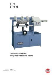
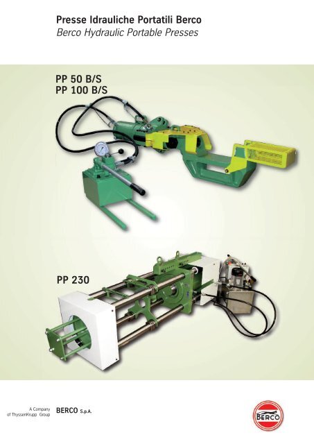
<strong>Presse</strong> <strong>Idrauliche</strong> <strong>Portatili</strong> <strong>Berco</strong><br />
<strong>Berco</strong> <strong>Hydraulic</strong> Portable <strong>Presse</strong>s<br />
PP 50 B/S<br />
PP 100 B/S<br />
PP 230<br />
A Company<br />
of ThyssenKrupp Group<br />
BERCO S.p.A.
Montaggio e smontaggio cingoli - Equipaggiamenti completi<br />
Servicing track chains - Complete equipment<br />
Nel settore delle macchine<br />
movimento terra, è particolarmente<br />
sentita l’esigenza di<br />
attrezzature potenti e versatili,<br />
per poter eseguire rapidamente,<br />
con minimo sforzo da parte<br />
dell’operatore, lavori di montaggio<br />
e smontaggio cingoli.<br />
Con le presse idrauliche portatili<br />
della serie “PP” e relativi<br />
equipaggiamenti, appositamente<br />
studiati per lo smontaggio<br />
e montaggio dei perni e<br />
delle boccole, <strong>Berco</strong> mette<br />
a disposizione una vasta<br />
gamma di specifiche attrezzature<br />
e componenti intercambiabili<br />
per i vari modelli di<br />
mezzi cingolati nazionali ed<br />
esteri. Gli equipaggiamenti<br />
completi della seri e “PP”, per<br />
interventi su cingoli, sono<br />
costituiti dalle presse idrauliche<br />
PP 50 B, PP 100 B e PP<br />
230, unitamente alle attrezzature<br />
base (S50 B e S100 B).<br />
The earth moving machinery<br />
sector keenly needs powerful<br />
and versatile equipment allowing<br />
fast, safe and easy removal and<br />
installation of track parts.<br />
<strong>Berco</strong> has introduced a new line<br />
of portable hydraulic track presses<br />
of the “PP” series, special tooling<br />
and interchangeable components<br />
to service both national and<br />
foreign crawler tractors. The<br />
complete equipment o f the “PP”<br />
series for servicing track chains<br />
comprises the PP 50 B, the PP<br />
100 B and the PP 230 hydraulic<br />
presses plus the basic tooling<br />
(S50 B and S100 B).<br />
All products shown in this document originate from <strong>Berco</strong> exclusively. Any references to Caterpillar (the Caterpillar word signs) are mentioned to communicate that the aforemenioned<br />
products are only suitable for Caterpillar machines with the corresponding model designation.
PP 50 B/S e PP 100 B/S - <strong>Presse</strong> <strong>Idrauliche</strong> <strong>Portatili</strong><br />
PP 50 B/S and PP 100 B/S - <strong>Hydraulic</strong> Portable <strong>Presse</strong>s<br />
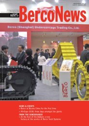
Pressa idraulica portatile PP 50 B/S<br />
<strong>Hydraulic</strong> portable press PP 50 B/S<br />
PP 50 B/S<br />
Equipaggiamento completo per<br />
montaggio e smontaggio perni<br />
e boccole, normali e di giunzione,<br />
composto da:<br />
• Pressa idraulica PP 50 B<br />
• Attrezzatura base S 50 B, con<br />
supporto a “C”.<br />
PP 100 B/S<br />
Equipaggiamento completo per<br />
montaggio e smontaggio perni<br />
e boccole, normali e di giunzione,<br />
composto da:<br />
• Pressa idraulica PP 100 B<br />
• Attrezzatura base S 100 B, con<br />
supporto a “C”.<br />
PP 50 B/S<br />
Complete equipment for removal<br />
and installation of track pins,<br />
master pins, bushings and<br />
master bushings, comprising:<br />
• <strong>Hydraulic</strong> press PP 50 B<br />
• Basic tooling set S 50 B, plus<br />
the “C” frame.<br />
PP 100 B/S<br />
Complete equipment for removal<br />
and installation of track pins,<br />
master pins, bushings and<br />
master bushings, comprising:<br />
• <strong>Hydraulic</strong> press PP 100 B<br />
• Basic tooling set S 100 B, plus<br />
the “C” frame.
Attrezzature base S 50 B e S 100 B (per PP 50 B e PP 100 B)<br />
Basic tooling sets S 50 B and S 100 B (for PP 50 B and PP 100 B)<br />
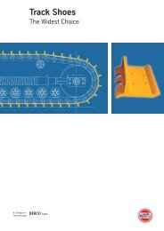
(Fig. 1)<br />
S 50 B<br />
Attrezzatura composta da un<br />
robusto supporto a “C”, da due<br />
tiranti, da un manicotto da due<br />
dadi e protezioni. La particolare<br />
struttura del supporto consente<br />
di effettuare interventi di<br />
estrazione e di introduzione<br />
perni e boccole in modo rapido<br />
e sicuro, in ogni condizione di<br />
impiego. Può essere utilizzata<br />
fino a 50 tonnellate di spinta.<br />
Massa approssimata 70 kg<br />
(155 lb).<br />
(Fig. 2)<br />
S 100 B<br />
Attrezzatura composta da un<br />
robusto supporto a “C”, da due<br />
tiranti, da un manicotto, da due<br />
dadi e protezioni. La particolare<br />
struttura del supporto consente<br />
di effettuare interventi di<br />
estrazione e di introduzione perni<br />
e boccole in modo rapido e<br />
sicuro, in ogni condizione di<br />
impiego. Può essere utilizzata<br />
fino a 93 tonnellate di spinta.<br />
Massa approssimata: kg 154<br />
(340 lb).<br />
(Fig. 3)<br />
Intervento su cingolo<br />
A seconda del tipo d’intervento<br />
da effettuare sul cingolo e del<br />
modello di trattrice, i vari<br />
equipaggiamenti dovranno essere<br />
integrati da specifici attrezzi<br />
ausiliari quali boccole, distanziali,<br />
punzoni ecc...<br />
Lo schema a lato mostra la tipica<br />
disposizione delle attrezzature<br />
occorrenti per l’estrazione del<br />
perno di un cingolo.<br />
In maniera analoga si procederà,<br />
con gli altri appositi attrezzi<br />
ausiliari, all’estrazione e<br />
all’introduzione delle boccole.<br />
(Fig. 1)<br />
S 50 B<br />
It consists of a robust “C” frame,<br />
two tie rods, a sleeve, two nuts<br />
and safety guards. The particular<br />
structure of the “C” frame allows<br />
safe and fast removal and<br />
installation of track pins and<br />
bushings, in all conditions of<br />
use. Up to 50 tonnes of ram<br />
thrust can be used. Approximate<br />
weight 70 kg (155 lb).<br />
(Fig. 2)<br />
S 100 B<br />
It consists of a robust “C” frame,<br />
two tie rods, a sleeve, two nuts<br />
and safety guards. The particular<br />
structure of the “C” frame allows<br />
safe and fast removal and<br />
installation of track pins and<br />
bushings, in all conditions of<br />
use. Up to 93 tonnes of ram<br />
thrust can be used. Approximate<br />
weight: 154 kg (340 lb).<br />
(Fig. 3)<br />
Servicing a track chain<br />
Depending on the kind of work<br />
to do on the track and the tractor<br />
model, the different basic sets<br />
shall be completed by adding<br />
specific auxiliary tools such as<br />
bushings, spacers, punches,<br />
etc.<br />
The illustration shows a typical<br />
set-up of the tooling necessary<br />
for removing a track pin.<br />
The same procedure, with other<br />
servicing tools, will be followed<br />
for removal and installation of<br />
track bushings.<br />
360<br />
Fig.1<br />
Fig. 2<br />
Fig. 3<br />
264
Cilindri<br />
Cylinders<br />
Fig. 4 Fig. 5<br />
CILINDRI<br />
I cilindri, a doppio effetto, che<br />
compongono le presse PP 50<br />
B e PP 100 B sono stati realizzati<br />
secondo le più moderne<br />
tecniche costruttive. L’elevato<br />
valore della corsa permette di<br />
effettuare, senza interruzione,<br />
le operazioni di montaggio e<br />
smontaggio dei cingoli. Le<br />
testate dei cilindri e le estremità<br />
degli steli sono predisposti<br />
per l’applicazione delle<br />
attrezzature necessarie per i<br />
vari interventi. I due seminnesti<br />
rapidi lato cilindro, vengono<br />
forniti solo se richiesti.<br />
CYLINDERS<br />
The double-acting cylinders<br />
equipping the PP 50 B and PP<br />
100 B presses have been built<br />
according to the latest techniques.<br />
The remarkable stroke length<br />
makes it possible to assemble<br />
and disassemble the track chains<br />
without any stoppages. Provisions<br />
on cylinder heads and piston<br />
rod ends allow fitting tooling for<br />
the different servicing operations.<br />
The two quick half couplers,<br />
cylinder side, are supplied only<br />
upon request.<br />
(Fig. 4)<br />
CP 50 B<br />
• Pressione max. bar 680<br />
(psi 9717)<br />
• Spinta max. tf 50<br />
(sh tonf 54.7)<br />
• Trazione max. tf 33<br />
(sh tonf 36.3)<br />
• Corsa mm 280 (11”)<br />
• Contenuto d’olio dm 3 2<br />
(in 3 122)<br />
• Massa approssimata Kg 50<br />
(lb 110.5)<br />
(Fig. 5)<br />
CP 100 B<br />
• Pressione max. bar 680<br />
(psi 9717)<br />
• Spinta max. tf 93<br />
(sh tonf 102.4)<br />
• Trazione max. tf 73<br />
(sh tonf 80.6)<br />
• Corsa mm 350 (13 3 /4”)<br />
• Contenuto d’olio dm 3 4,64<br />
(in 3 283)<br />
• Massa approssimata Kg<br />
100 (lb 221)<br />
1460<br />
1175<br />
(Fig. 4)<br />
CP 50 B<br />
• Max. pressure 680 bar<br />
(9717 psi)<br />
• Max. push 50 tf<br />
(54.7 sh tonf)<br />
• Max. pull 33 tf<br />
(36.3 sh tonf)<br />
• Stroke 280 mm (11”)<br />
• Oil capacity 2 dm 3<br />
(122 in 3 )<br />
• Approximate weight 50 kg<br />
(110.5 lb)<br />
(Fig. 5)<br />
CP 100 B<br />
• Max. pressure 680 bar<br />
(9717 psi)<br />
• Max. push 93 tf<br />
(102.4 sh tonf)<br />
• Max. pull 73 tf<br />
(80.6 sh tonf)<br />
• Stroke 350 mm (13 3 /4”)<br />
• Oil capacity 4.64 dm 3<br />
(283 in 3 )<br />
• Approximate weight 100 kg<br />
(221 lb)
Pompe<br />
Pumps<br />
Fig. 6 Fig. 7<br />
POMPE<br />
Con le sigle PM 2 A e PE 1 A si<br />
identificano solamente le pompe,<br />
con l’esclusione quindi dei tubi<br />
flessibili e dei seminnesti rapidi<br />
lato tubo che nelle immagini<br />
risultano montati sulla pompa:<br />
tubi e seminnesti verranno forniti<br />
solo se richiesti.<br />
(Fig.6)<br />
PM 2 A - pompa manuale<br />
Impiegabile in entrambe le<br />
presse idrauliche da 50 e da<br />
100 tonnellate. Funzionamento<br />
a due stadi di pressione con<br />
passaggio automatico dal primo<br />
al secondo stadio. È dotata di<br />
valvola manuale a quattro vie con<br />
leva a tre posizioni e manometro.<br />
PUMPS<br />
Designations PM 2 A and PE 1<br />
A refer only to pumps less hoses<br />
and less the quick half couplers,<br />
hose side, which in the<br />
photographs are shown mounted<br />
on the pump; hoses and half<br />
couplers will be supplied<br />
only if requested.<br />
(Fig.6)<br />
PM 2 A - hand pump<br />
It is used on both the 50 and 100<br />
tonne hydraulic presses. It is a<br />
two-stage pump, with automatic<br />
switching from the first to the<br />
second stage. It is equipped<br />
with a four-way manual control<br />
valve with a three-position lever<br />
and pressure gauge.<br />
(Fig. 7)<br />
PE 1 A - pompa elettrica<br />
Impiegabile in alternativa alla<br />
pompa manuale; in tal caso le<br />
presse idrauliche vanno richieste<br />
con le sigle PPE 50 B e PPE<br />
100 B. Funzionamento a due<br />
stadi di pressione con passaggio<br />
automatico dal primo al secondo<br />
stadio. È dotata di distributore<br />
manuale a quattro vie con leva<br />
a tre posizioni di manometro,<br />
di valvola interna di 1460 sicurezza<br />
tarata al montaggio 1175 per la<br />
massima pressione di esercizio<br />
e di valvola registrabile all’esterno<br />
per tutte le pressioni intermedie<br />
a seconda delle esigenze di<br />
impiego. Possibilità di operare<br />
a ciclo continuo con pressioni fino<br />
a bar 500 (psi 7140) e a cicli<br />
intermittenti di sei minuti alla<br />
massima pressione di esercizio.<br />
Possibilità di effettuare<br />
l’avviamento del motore anche<br />
con circuito idraulico in pressione.<br />
(Fig. 7)<br />
PE 1 A - power-driven pump<br />
An alternative to the hand pump.<br />
In this case, type designation for<br />
the hydraulic presses is PPE 50<br />
B and PPE 100 B. It is a twostage<br />
pump with automatic<br />
switching from the first to the<br />
second stage. It is equipped<br />
with a four-way manual control<br />
valve with a three-position lever<br />
and pressure gauge, a safety<br />
relief valve (inner), which has<br />
been factory-set for maximum<br />
pressure and an adjustable<br />
valve (outer) for all intermediate<br />
pressure values depending on<br />
job requirements. It can be<br />
either run continuously up to<br />
500 bar (7140 psi) or jogged<br />
at intervals of six minutes at<br />
the maximum working pressure.<br />
It is possible to switch on the<br />
electric motor even if the<br />
hydraulic circuit is under<br />
pressure.
Attrezzature specifiche<br />
Montaggio - smontaggio perni e boccole<br />
Specific tooling sets<br />
Pins and bushings installation - removal<br />
Fig. 8<br />
Montaggio - smontaggio perno<br />
Fig. 8<br />
Pin installation - removal<br />
S<br />
•Attrezzature in dotazione con la pressa<br />
Equipment supplied with the press<br />
•Attrezzature fornite su richiesta<br />
Equipment supplied on request<br />
Fig. 9<br />
Montaggio - smontaggio boccola<br />
Fig. 9<br />
Bushing installation - removal<br />
Denominazione Denominazione<br />
A Tiranti B Supporto a “C”<br />
C Dadi D Vite<br />
F Manicotto G Adattatore (per perno)<br />
H Riduzione I Punzone<br />
L Boccola M Perno<br />
P<br />
S<br />
Incudine (solo per<br />
boccole giunzione)<br />
Incudine<br />
(smontaggio boccole)<br />
W Adattatore<br />
R Incudine (perni)<br />
V Incudine (boccole)<br />
Description Description<br />
A Tie-rods B “C” frame<br />
C Nuts D Screw<br />
F Sleeve G Adapter (for pin)<br />
H Reduction I Punch<br />
L Bushing M Pin<br />
P<br />
S<br />
Anvil<br />
(master bushings only)<br />
Anvil<br />
(bushing removal)<br />
W Adapter<br />
R Anvil (pins)<br />
V Anvil (bushings)
A<br />
B<br />
D<br />
C<br />
Dati tecnici<br />
Technical data<br />
Dimensioni e peso Dimensions and weight PP50 B/S PP100 B/S<br />
Lunghezza con protezione (A) Length with safety guard (A) mm 1460 57 1 /2” mm 1707 67 7 /32”<br />
Lunghezza senza protezione (B) Length without safety guard (B) mm 1175 46 1 /4” mm 1432 56 3 /8”<br />
Larghezza (C) Width (C) mm 264 10 7 /16” mm 325 12 13 /16”<br />
Altezza (D) Height (D) mm 360 14 3 /16” mm 435 17 1 /8”<br />
Massa approssimata Approximate weight Kg 133 lb 296 Kg 255 lb 566<br />
Cilindri<br />
Cylinders<br />
Capacità di lavoro Operating specifications CP50 B CP100 B<br />
Spinta max. Max. ram force tf 50 sh tons 54.7 tf 93 sh tons 102.4<br />
Trazione max. Max. traction of rams tf 33 sh tons 36.3 tf 73 sh tons 80.6<br />
Pressione massima Maximum pressure bar 680 psi 9717 bar 680 psi9717<br />
Corsa Stroke mm 280 11” mm 350 13 3 /4”<br />
Contenuto olio Oil capacity dm 3 2 in 3 122 dm 3 4.64 in 3 283<br />
Massa approssimata Approximate weight Kg 50 lb 110.5 Kg 100 lb 221<br />
Pompa Manuale PM 2 A<br />
Hand Pump PM 2 A<br />
Capacità di lavoro<br />
Operating specifications<br />
Portata per colpo:<br />
Capacity per stroke:<br />
1° stadio 1st. stage dm 3 0.125 a bar 22 in 3 7.75 at psi 310<br />
2° stadio 2nd. stage dm 3 0.005 a bar 680 in 3 0.30 at psi 9717<br />
Sforzo sulla leva Handle lever effort Kg 40 Ib 89<br />
Capacità serbatoio Tank capacity litri 7.5 in 3 458<br />
Massa approssimata (senza olio) Approximate weight (less oil) Kg 20.5 Ib 46<br />
Pompa Elettrica PE 1 A<br />
Power-Driven Pump PE 1 A<br />
Capacità di lavoro<br />
Operating specifications<br />
Motore elettrico Electric motor KW 1,5 Hp 2<br />
Portata bassa pressione Low pressure delivery dm 3 /min 10.6 a bar 80 in 3 /min 646 at psi 1140<br />
Portata alta pressione High pressure delivery dm 3 /min 1.1 a bar 680 in 3 /min 67 at psi 9717<br />
Valvola manuale Manual valve a 4 vie 3 posizioni 4 way 3 positions<br />
Capacità serbatoio Tank capacity litri 20 in 3 1220<br />
Massa approssimata (senza olio) Approximate weight (less oil) Kg. 70 Ib 155
PP 230 - Pressa Idraulica Portatile<br />
PP 230 - <strong>Hydraulic</strong> Portable Press<br />
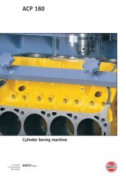
Fig. 10<br />
Pressa portatile PP 230 con pompa elettrica<br />
Fig. 10<br />
Portable press PP 230 with power-driven pump<br />
Per venire incontro alle nuove<br />
necessità di intervento su<br />
escavatori del settore<br />
“mining” e dozer di notevole<br />
dimensione (classe D9 in<br />
poi), <strong>Berco</strong> propone una pressa<br />
portatile oleodinamica di<br />
notevole potenza di spinta per<br />
lo smontaggio ed il montaggio<br />
dei perni di giunzione delle<br />
catene direttamente sul<br />
campo.<br />
La pressa, dotata delle specifiche<br />
attrezzature (da richiedere<br />
espressamente) per il tipo<br />
di catena da servire, permette<br />
di dividerla in modo di agevolare<br />
il successivo intervento<br />
di riparazione o revisione.<br />
Dotata di un sistema per il<br />
sollevamento ed il bilanciamento,<br />
permette di lavorare<br />
in condizioni ottimali per l’intervento<br />
sul mezzo cingolato.<br />
La centralina oleodinamica,<br />
dotata di un motore elettrico,<br />
risulta maneggevole per lo<br />
spostamento. I tubi flessibili<br />
di collegamento alla pressa,<br />
grazie alla lunghezza adeguata<br />
permettono di lavorare ad<br />
una corretta distanza dal<br />
punto d’intervento, avendo<br />
sotto controllo i movimenti<br />
della pressa.<br />
To meet the new needs of<br />
servicing excavators in the<br />
mining sector and dozers of<br />
considerable size (class D9<br />
upwards), <strong>Berco</strong> offers a<br />
portable hydraulic press of<br />
considerable power for<br />
removing and installing the<br />
master pins of chains directly<br />
in the field.<br />
The press, fitted out with the<br />
specific equipment (to be<br />
expressly requested) for the<br />
type of chain to service,<br />
enables splitting the chain so<br />
as to facilitate the subsequent<br />
work of repair or overhaul.<br />
Equipped with a system for<br />
lifting and balancing, it<br />
enables working in optimal<br />
conditions for servicing<br />
crawler tractors.<br />
The hydraulic power pack,<br />
equipped with an electric<br />
motor, is easy to handle for<br />
moving. The hoses for<br />
connecting to the press,<br />
thanks to their adequate<br />
length, allow working at a<br />
correct distance from the<br />
point of servicing, keeping the<br />
movements of the press<br />
under control.
Fig. 11 e 12<br />
Smontaggio perno con pressa<br />
PP 230<br />
Fig. 11 and 12<br />
Removing pin with press PP 230<br />
Fig. 11<br />
Fig. 12<br />
La pressa è composta da un<br />
cilindro con due testate nelle<br />
quali trovano alloggiamento e<br />
scorrono quattro tiranti, che,<br />
assieme alla piastra di estremità,<br />
costituiscono il telaio.<br />
I tiranti vengono tolti o fatti<br />
scorrere nelle loro sedi al fine<br />
di poter accedere agevolmente<br />
alla sezione di catena su cui<br />
intervenire e poi mediante dadi<br />
e distanziatori vengono fissati<br />
alla piastra di estremità che<br />
porta l’incudine di contrasto al<br />
cilindro di spinta.<br />
Una piastra intermedia rimovibile,<br />
bloccata nella posizione voluta<br />
sui tiranti, porta l’attrezzatura di<br />
guida del punzone o del perno<br />
durante le operazioni di<br />
smontaggio/montaggio.<br />
Nei cingolati più grossi le<br />
operazioni si dovranno eseguire<br />
in due fasi, data la lunghezza<br />
dei perni su cui intervenire.<br />
Sul cilindro sono montati due<br />
seminnesti per il collegamento<br />
rapido ai tubi della centrale<br />
oleodinamica.<br />
Detta centrale è provvista<br />
di un distributore manuale<br />
a tre posizioni per il controllo<br />
della direzione di lavoro del<br />
pistone, di un manomentro per<br />
la visualizzazione della pressione<br />
di lavoro che è regolata tramite<br />
una valvola posizionata sul<br />
coperchio della centrale.<br />
Una valvola di sicurezza interna<br />
viene tarata in fase di collaudo<br />
e garantisce di non superare la<br />
pressione massima d’esercizio<br />
a cui deve lavorare la pressa.<br />
The press is composed of a<br />
cylinder with two heads in which<br />
are housed and run four<br />
tie-rods that, together with the<br />
end plate, comprise the frame.<br />
The tie-rods are removed or<br />
made to run in their seats in<br />
order to be able to gain easy<br />
access to the section of chain on<br />
which to work and then nuts<br />
and spacers are used to secure<br />
them to the end plate that carries<br />
the anvil to the ram.<br />
A removable intermediate plate,<br />
locked in the desired position<br />
on the tie-rods, carries the<br />
equipment guiding the punch<br />
or pin during disassembly/<br />
assembly.<br />
On larger crawler tractors, this<br />
work must be performed in two<br />
phases given the length of the<br />
pins on which to work.<br />
Two half-couplers are fitted on<br />
the cylinder for rapid connection<br />
to the hoses of the hydraulic<br />
power pack.<br />
This power pack is equipped<br />
with a manual three-position<br />
control valve to control the<br />
working direction of the piston<br />
and a pressure gauge for viewing<br />
the working pressure that is<br />
regulated by a valve located on<br />
the cover of the power pack.<br />
An internal safety valve is<br />
calibrated in the phase of testing<br />
and ensures the press’s<br />
maximum working pressure is<br />
not exceeded.
A<br />
C<br />
A<br />
B<br />
A<br />
B<br />
C<br />
C<br />
C<br />
C<br />
B<br />
B<br />
B<br />
Dati tecnici<br />
Technical data<br />
Capacità di lavoro<br />
Operating specifications<br />
Spinta max. Max. ram force tf 215 sh tons 236<br />
Corsa max. Max. stroke mm 320 12 1 /2”<br />
Diametro dello stelo Rod diameter mm 140 5 1 /2”<br />
Pressione max. Max. pressure bar 520 psi 7400<br />
Pressione di accostamento Low pressure bar 80 psi 1150<br />
Portata bassa pressione Low pressure delivey l/min 10.6 in 3 /min 646<br />
Portata alta pressione High pressure delivery l/min 1.1 in 3 /min 67<br />
Capacità del serbatoio Tank capacity litri 20 in 3 1220<br />
Motore elettrico Electric motor Kw 1.5 HP 2<br />
Dimensioni e peso<br />
Dimensions and weight<br />
Lunghezza (A) Lenght (A) mm 2300 90 1 /2”<br />
Larghezza (B) Width (B) mm 530 20 7 /8”<br />
Altezza (C) Height (C) mm 700 27 1 /2”<br />
Massa centralina oleodinamica Weight of hydraulic power pack Kg 70 lb 155<br />
Massa pressa (cilindro + telaio) Press weight (cylinder + frame) Kg 1200 lb 2660
BERCO S.p.A.<br />
Via 1° Maggio, 237<br />
44034 Copparo (FE) Italy<br />
Phone +39 0532 864 111<br />
Fax +39 0532 864 163<br />
www.berco.com<br />
specialdevices@berco.com<br />
01203.WA194IG000<br />
Published by <strong>Berco</strong> Communications Dept.<br />
ISO 9001 Cert. n. 0029/6<br />
ISO 14001 Cert. n. 0009A/4<br />
All manufacturers’s names, numbers, symbols and descriptions are used for reference purposes only. All parts listed are of <strong>Berco</strong> original<br />
production.The specifications and processes described in this brochure are subject to change without notice