P7 - P 4.5 - BFT
P7 - P 4.5 - BFT
P7 - P 4.5 - BFT

Create successful ePaper yourself
Turn your PDF publications into a flip-book with our unique Google optimized e-Paper software.
D811293 ver. 02 14-02-03<br />
I<br />
GB<br />
AUTOMAZIONI A PISTONE PER CANCELLI A BATTENTE<br />
PISTON AUTOMATION FOR SWING GATES<br />
8 027908 171559<br />
<strong>P7</strong> - P <strong>4.5</strong><br />
ISTRUZIONI D'USO E DI INSTALLAZIONE<br />
INSTALLATION AND USER'S MANUAL<br />
Via Lago di Vico, 44<br />
36015 Schio (VI)<br />
Tel.naz. 0445 696511<br />
Tel.int. +39 0445 696533<br />
Fax 0445 696522<br />
Internet: www.bft.it<br />
E-mail: sales@bft.it
2 - <strong>P7</strong> - P<strong>4.5</strong> Ver. 02<br />
D811293_02
CLOSE<br />
D811293_02<br />
MANUALE D’USO<br />
ITALIANO<br />
Nel ringraziarVi per la preferenza accordata a questo prodotto, la ditta è certa che da esso otterrete le prestazioni necessarie al Vostro uso.<br />
Leggete attentamente l’opuscolo “Avvertenze” ed il “Libretto istruzioni” che accompagnano questo prodotto in quanto forniscono importanti indicazioni<br />
riguardanti la sicurezza, l’installazione, l’uso e la manutenzione. Questo prodotto risponde alle norme riconosciute della tecnica e della disposizioni relative<br />
alla sicurezza. Confermiamo che è conforme alle seguenti norme: CAN/CSA-C22.2 No. 247-92 UL Std. No. 325 (Certificato 1002906 in data 16 ottobre<br />
2000).<br />
1) GENERALITÀ<br />
Pistone oleodinamico compatto e robusto, disponibile in diverse versioni a seconda delle esigenze e del campo di utilizzo. Tutti i modelli sono senza blocchi<br />
(reversibili) e, per mantenere il blocco, necessitano di elettroserratura. Per rendere più agevole la manovra manuale, si può attivare lo sblocco tramite<br />
il pomello, al quale si ha l’accesso con l’apposita chiave. La forza di spinta si regola con estrema precisione mediante due valvole by-pass che costituiscono<br />
la sicurezza antischiacciamento. Il funzionamento a fine corsa è regolato elettronicamente nel quadro di comando mediante temporizzatore. Tutti i modelli<br />
sono disponibili con rallentamento in fase di chiusura.<br />
2) SICUREZZA<br />
L’automazione, se installata ed utilizzata correttamente, soddisfa il grado di sicurezza richiesto. Tuttavia è opportuno osservare alcune regole di<br />
comportamento per evitare inconvenienti accidentali. Prima di usare l’automazione, leggere attentamente le istruzioni d’uso e conservarle per<br />
consultazioni future.<br />
• Tenere bambini, persone e cose fuori dal raggio d’azione dell’automazione, in particolare durante il funzionamento.<br />
• Non lasciare radiocomandi o altri dispositivi di comando alla portata dei bambini onde evitare azionamenti involontari dell’automazione.<br />
• Non contrastare volontariamente il movimento dell’anta.<br />
• Non tentare di aprire manualmente il cancello se non è stata sbloccata l’elettroserratura con l’apposita chiave.<br />
• Non modificare i componenti dell’automazione.<br />
• In caso di malfunzionamento, togliere l’alimentazione, attivare lo sblocco di emergenza per consentire l’accesso e richiedere l’intervento di un tecnico<br />
qualificato (installatore).<br />
• Per ogni operazione di pulizia esterna, togliere l’alimentazione di rete.<br />
• Tenere pulite le ottiche delle fotocellule ed i dispositivi di segnalazione luminosa. Controllare che rami ed arbusti non disturbino i dispositivi di sicurezza<br />
(fotocellule).<br />
• Per qualsiasi intervento diretto all’automazione, avvalersi di personale qualificato (installatore).<br />
• Annualmente far controllare l’automazione da personale qualificato.<br />
3) MANOVRA DI EMERGENZA<br />
Nei casi di emergenza, per esempio in mancanza di energia elettrica, per sbloccare il cancello, bisogna aprire l’elettroserratura con l’apposita chiave e<br />
aprire manualmente l’anta, eventualmente accedere al pomello di sblocco per agevolare la manovra. Per avere l’accesso al pomello di sblocco si deve<br />
spostare il coperchietto nel senso indicato dalla freccia (fig.1) fino a scoprire la serratura, inserire la chiave, ruotare in senso orario di 90° e alzare l’intero<br />
coprisblocco tirando per la medesima. Il pomello deve essere ruotato per quanto è consentito nel senso indicato dalle frecce.<br />
OPEN per sbloccare: il cancello è così apribile manualmente con facilità. CLOSE per bloccare: girare il pomello in senso orario fino al completo bloccaggio<br />
ripristinando il funzionamento elettrico dell’attuatore. Anche in caso di malfunzionamento dell’attuatore o di mancanza di corrente si può far uso<br />
dell’elettroserratura per chiudere il cancello.<br />
Fig. 1<br />
OPEN<br />
<strong>P7</strong> - P<strong>4.5</strong> Ver. 02 - 3
CLOSE<br />
ENGLISH<br />
USER’S MANUAL<br />
Thank you for buying this product, our company is sure that you will be more than satisfied with the product’s performance. The product is supplied with<br />
a “Warnings” leaflet and an “Instruction booklet”. These should both be read carefully as they provide important information about safety, installation,<br />
operation and maintenance. This product complies with the recognised technical standards and safety regulations.We declare that this product is in<br />
conformity with the following directives: CAN/CSA-C22.2 No. 247-92 UL Std. No. 325 (Certificate: 1002906 Date Issued: October 16, 2000).<br />
D811293_02<br />
1) GENERAL OUTLINE<br />
A compact sturdy hydraulic piston, available in various versions according to the user’s requirements and type of operating. All models are supplied without<br />
locks (reversible), and an electric lock is required to keep them blocked. To make the manual manoeuvre easier, the lock can be released by means of<br />
a knob which can be reached using the appropriate key. The pushing force is adjusted with extreme precision by means of two by-pass valves which<br />
provide antisquash safety. The end-of-stroke operation is electronically set in the control panel by means of a timer. All models are available with slowdown<br />
function during the closing .<br />
2) SAFETY<br />
If correctly installed and used, this automation device satisfies the required safety level standars. However, it is advisable to observe some practical rules<br />
in order to avoid accidental problems. Before using the automation device, carefully read the operation instructions and keep them for future reference.<br />
• Keep children, persons and things outside the automation working area, particularly during its operation.<br />
• Keep radio control or other control devices out of children’s reach, in order to avoid any unintentional automation activation.<br />
• Do not intentionally oppose the leaf movement.<br />
• Do not attempt to open the gate manually, if the electric lock has not been released by means of the appropriate key.<br />
• Do not modify the automation components.<br />
• In case of malfunction, disconnect the power supply, activate the emergency release to have access t the automation and request the assistance of<br />
qualified technician (installer).<br />
• Before proceeding to any outside cleaning operation, disconnect the mains power supply.<br />
• Keep the photocell optical components and light signal devices clean. Check that the safety devices (photocells) are not obscured by branches or shrubs.<br />
• For any direct assistance to the automation system, request the help of a qualified technician (installer).<br />
• Have qualified personnel check the automation system once a year.<br />
3) EMERGENCY MANOEUVRE<br />
In case of emergency, for example when the electrical power is disconnected, open the electric lock by means of the appropriate key to release the gate,<br />
and open the leaf manually; you may also reach the release knob to facilitate the manoeuvre. In order to get access to the release knob, move the small<br />
cap in the direction indicated by the arrow (fig.1) to reveal the lock, insert the key, turn it clockwise by 90° and lift the entire release cover by pulling with<br />
the key. The knob must be allowed to turn as far as possible in the direction indicated by the arrows. OPEN to release: the gate can be opened manually<br />
with ease. CLOSE to lock : turn the knob clockwise until it is completely locked, and so restore the actuator electrical operation. The electric lock can also<br />
be used to keep the block of the gate in case of actuator malfunction or current failure.<br />
Fig. 1<br />
OPEN<br />
4 - <strong>P7</strong> - P<strong>4.5</strong> Ver. 02
D811293_02<br />
Nel ringraziarVi per la preferenza accordata a questo prodotto, la ditta è<br />
certa che da esso otterrete le prestazioni necessarie al Vostro uso.<br />
Leggete attentamente l’opuscolo “Avvertenze” ed il “Libretto istruzioni”<br />
che accompagnano questo prodotto in quanto forniscono importanti indicazioni<br />
riguardanti la sicurezza, l’installazione, l’uso e la manutenzione.<br />
Questo prodotto risponde alle norme riconosciute della tecnica e della<br />
disposizioni relative alla sicurezza. Confermiamo che è conforme alle<br />
seguenti norme: CAN/CSA-C22.2 No. 247-92 UL Std. No. 325 (Certificato<br />
1002906 in data 16 ottobre 2000).<br />
<br />
1) SICUREZZA GENERALE<br />
ATTENZIONE! Una installazione errata o un uso improprio del prodotto,<br />
può creare danni a persone, animali o cose.<br />
Leggete attentamente l’opuscolo ”Avvertenze” ed il ”Libretto istruzioni” che<br />
accompagnano questo prodotto, in quanto forniscono importanti indicazioni<br />
riguardanti la sicurezza, l’installazione, l’uso e la manutenzione.<br />
• Smaltire i materiali di imballo (plastica, cartone, polistirolo, ecc.) secondo<br />
quanto previsto dalle norme vigenti. Non lasciare buste di nylon e<br />
polistirolo a portata dei bambini.<br />
• Conservare le istruzioni per allegarle al fascicolo tecnico e per consultazioni<br />
future.<br />
• Questo prodotto è stato progettato e costruito esclusivamente per<br />
l’utilizzo indicato in questa documentazione. Usi non indicati in questa<br />
documentazione potrebbero essere fonte di danni al prodotto e fonte di<br />
pericolo.<br />
• La Ditta declina qualsiasi responsabilità derivante dall’uso improprio o<br />
diverso da quello per cui è destinato ed indicato nella presente documentazione.<br />
• Non installare il prodotto in atmosfera esplosiva.<br />
• La Ditta declina qualsiasi responsabilità dall’inosservanza della Buona<br />
Tecnica nella costruzione delle chiusure (porte, cancelli, ecc.), nonchè<br />
dalle deformazioni che potrebbero verificarsi durante l’uso.<br />
• Togliere l’alimentazione elettrica, prima di qualsiasi intervento sull’impianto.<br />
Scollegare anche eventuali batterie tampone se presenti.<br />
• Prevedere sulla rete di alimentazione dell’automazione, un interruttore<br />
o un magnetotermico onnipolare con distanza di apertura dei contatti<br />
uguale o superiore a 0.11 in (3mm).<br />
• Verificare che a monte della rete di alimentazione, vi sia un interruttore<br />
differenziale con soglia da 0.03A.<br />
• Verificare se l’impianto di terra è realizzato correttamente: collegare<br />
tutte le parti metalliche della chiusura (porte, cancelli, ecc.) e tutti i<br />
componenti dell’impianto provvisti di morsetto di terra.<br />
• Applicare tutti i dispositivi di sicurezza (fotocellule, coste sensibili, ecc.)<br />
necessari a proteggere l’area da pericoli di schiacciamento,<br />
convogliamento, cesoiamento.<br />
• Applicare almeno un dispositivo di segnalazione luminosa (lampeggiante)<br />
in posizione visibile, fissare alla struttura un cartello di Attenzione.<br />
• La Ditta declina ogni responsabilità ai fini della sicurezza e del buon<br />
funzionamento dell’automazione se vengono impiegati componenti di<br />
altri produttori.<br />
• Usare esclusivamente parti originali per qualsiasi manutenzione o<br />
riparazione.<br />
• Non eseguire alcuna modifica ai componenti dell’automazione se non<br />
espressamente autorizzata dalla Ditta.<br />
• Istruire l’utilizzatore dell’impianto per quanto riguarda i sistemi di comando<br />
applicati e l’esecuzione dell’apertura manuale in caso di emergenza.<br />
• Non permettere a persone e bambini di sostare nell’area d’azione<br />
dell’automazione.<br />
• Non lasciare radiocomandi o altri dispositivi di comando alla portata dei<br />
bambini onde evitare azionamenti involontari dell’automazione.<br />
• L’utilizzatore deve evitare qualsiasi tentativo di intervento o riparazione<br />
dell’automazione e rivolgersi solo a personale qualificato.<br />
• Tutto quello che non è espressamente previsto in queste istruzioni, non<br />
è permesso.<br />
<br />
INSTALLARE L’APRICANCELLO SOLO QUANDO:<br />
• L’attuatore risulta idoneo per la tipologia costruttiva del cancello e per<br />
la classe di utilizzo del cancello.<br />
• Tutti i punti di schiacciamento evidenti sono protetti o schermati.<br />
• L’apricancello è concepito per essere installato solo su cancelli utilizzati<br />
per il passaggio di veicoli. Per i pedoni devono essere previsti accessi<br />
separati.<br />
• Il cancello deve essere installato in una posizione tale da garantire una<br />
distanza sufficiente tra il cancello e le strutture adiacenti durante<br />
MANUALE PER L’INSTALLAZIONE<br />
ITALIANO<br />
l’apertura e la chiusura, al fine di ridurre il rischio di intrappolamento.<br />
I cancelli a battente non potranno essere aperti in aree di pubblico<br />
accesso.<br />
• Il cancello deve essere installato correttamente e deve funzionare liberamente<br />
in entrambe le direzioni prima dell’installazione<br />
dell’apricancello. Non serrare eccessivamente la frizione dell’attuatore<br />
o la valvola di sfiato della pressione per rimediare ad un cancello<br />
danneggiato.<br />
IN CASO DI APRICANCELLI CON COMANDO UOMO PRESENTE:<br />
• I comandi dell’apricancello devono essere posizionati in modo tale che<br />
l’utilizzatore abbia una visuale completa dell’area del cancello quando<br />
il cancello è in movimento.<br />
• Dovrà essere posizionato vicino ai comandi un cartello recante la scritta<br />
“AVVERTENZA” dalle lettere alte almeno 6,4 mm. e la seguente<br />
dichiarazione: “ Il cancello in movimento è in grado di causare lesioni<br />
o morte - non azionate il cancello quando il percorso non è libero”.<br />
• Non dovranno essere utilizzati dispositivi di chiusura automatici (quali<br />
temporizzatori, rilevatori di spira o dispositivi similari).<br />
• Non dovrà essere collegato nessun altro dispositivo di attivazione.<br />
I comandi devono essere sufficientemente lontani dal cancello in modo che<br />
l’utente non possa venire a contatto con il cancello quando utilizza tali<br />
comandi. I comandi previsti per il resettaggio dell’attuatore dopo due<br />
attivazioni successive del dispositivo/i contro l’intrappolamento devono<br />
essere posizionati sulla linea visiva del cancello. I comandi esterni o<br />
facilmente accessibili dovranno essere dotati di protezione al fine di<br />
impedirne l’utilizzo non autorizzato.<br />
I segnali di avvertenza e i cartelli devono essere installati in una posizione<br />
visibile nell’area del cancello.<br />
IN CASO DI ATTUATORI CHE UTILIZZANO UN SENSORE CON RILE-<br />
VAMENTO SENZA CONTATTO:<br />
• Leggere le istruzioni sul posizionamento dei sensori senza contatto per<br />
ogni tipo di applicazione.<br />
• Provvedere affinché venga ridotto al minimo il rischio di intervento di<br />
disturbi come quando, ad esempio, il veicolo fa scattare il sensore<br />
mentre il cancello è ancora in movimento.<br />
• Posizionare uno o più sensori senza contatto dove esiste il rischio di<br />
intrappolamento o ostruzione, ad esempio lungo il perimetro raggiunto<br />
dal cancello in movimento.<br />
IN CASO DI ATTUATORI CHE UTILIZZANO UN SENSORE CON RILE-<br />
VAMENTO A CONTATTO (COSTA SENSIBILE O EQUIVALENTE):<br />
• Dovranno essere installati uno o più sensori di contatto sul punto di<br />
serraggio di cancelli verticali a cardine per passaggio veicolare.<br />
• Dovrà essere installato un sensore con contatto a circuito permanente<br />
i cui cablaggi dovranno essere disposti in modo tale che la comunicazione<br />
tra il sensore e l’apricancello non sia soggetta a danni meccanici.<br />
• Dovrà essere installato un sensore con contatto senza fili quale ad<br />
esempio un sensore che trasmette segnali di frequenze radio (RF)<br />
all’apricancello per le funzioni di protezione contro l’intrappolamento nei<br />
casi in cui la trasmissione dei segnali non sia ostacolata o impedita dalla<br />
struttura dell’edificio, dal paesaggio naturale o da ostacoli similari. Il<br />
sensore con contatto senza fili dovrà funzionare conformemente alle<br />
condizioni per l’utilizzo finale previste.<br />
<br />
IMPORTANTI PRESCRIZIONI DI SICUREZZA<br />
ATTENZIONE: al fine di ridurre il rischio di danni fisici o morte:<br />
• Leggere e osservare tutte le istruzioni.<br />
• Non permettere ai bambini di utilizzare o giocare con i comandi del<br />
cancello. Tenere il telecomando fuori dalla portata dei bambini.<br />
• Tenere lontani oggetti e persone dal cancello. NON E’ PERMESSO<br />
ATTRAVERSARE IL PERCORSO ESEGUITO DAL CANCELLO IN<br />
MOVIMENTO.<br />
• Controllare mensilmente il corretto funzionamento del cancello. Il cancello<br />
DEVE invertire marcia in caso di contatto con oggetti rigidi e deve<br />
fermarsi quando un oggetto attiva i sensori senza contatto. Dopo aver<br />
regolato la forza o il finecorsa, ricontrollare l’apricancello.<br />
La mancata regolazione e l’omissione del successivo controllo<br />
dell’apricancello possono aumentare il rischio di danni fisici e di morte.<br />
• Utilizzare lo sblocco di emergenza solo a cancello fermo.<br />
• ESEGUIRE UNA MANUTENZIONE REGOLARE DEL CANCELLO.<br />
Leggere il manuale dell’utilizzatore. Eventuali riparazioni alle parti<br />
meccaniche del cancello devono essere eseguite da personale qualifi-<br />
<strong>P7</strong> - P<strong>4.5</strong> Ver. 02 - 5
ITALIANO<br />
cato.<br />
• L’entrata è riservata ai veicoli. Prevedere un’entrata separata per i<br />
pedoni.<br />
• Conservare le presenti istruzioni.<br />
2) GENERALITÀ<br />
Pistone oleodinamico compatto e robusto, disponibile in diverse versioni a<br />
seconda delle esigenze e del campo di utilizzo.<br />
Tutti i modelli sono senza blocchi (reversibili) e, per mantenere il blocco,<br />
necessitano di elettroserratura.<br />
Per rendere più agevole la manovra manuale, si può attivare lo sblocco<br />
tramite il pomello, al quale si ha l’accesso con l’apposita chiave.<br />
La forza di spinta si regola con estrema precisione mediante due valvole bypass<br />
che costituiscono la sicurezza antischiacciamento. Il funzionamento<br />
a fine corsa è regolato elettronicamente nel quadro di comando mediante<br />
temporizzatore. Tutti i modelli sono disponibili con rallentamento in fase<br />
di chiusura.<br />
3) PARTI PRINCIPALI DELL’AUTOMAZIONE (Fig.1)<br />
M) Motore monofase 2 poli protetto da disgiuntore termico.<br />
P) Pompa idraulica a lobi.<br />
D) Distributore con valvole di regolazione.<br />
C) Cilindro con pistone.<br />
CS) Copristelo.<br />
S) Serbatoio.<br />
SB) Sblocco.<br />
T) Testata con valvola regolazione rallentamento.<br />
F) Fondello con snodo.<br />
Componenti in dotazione: attacchi al pilastro e al cancello - chiave di<br />
sblocco personalizzata - condensatore di marcia - manuale istruzione.<br />
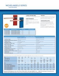
4) DATI TECNICI<br />
Mod. <strong>P7</strong> - Mod. P<strong>4.5</strong><br />
Alimentazione .......................................................120Vac±10% - 50Hz (*)<br />
Motore ......................................................................................... 2800min -1<br />
Potenza assorbita ............................................................................. 250W<br />
Condensatore ....................................................................................... 8µF<br />
Corrente assorbita ...............................................................................1.1A<br />
Pressione max 5MPa (50bar) - 4MPa (40bar).....104472.2 - 83541.7 lb/ft 2<br />
Portata pompa ................... 0.6l/min - 0.9l/min.............0.16 - 0.24 gal/min<br />
Forza di spinta ....................... 8000N - 6500N ............1798.5 - 1461.3 lbf<br />
Forza di trazione .................... 6500N - 5200N.............1461.3 - 1169.0 lbf<br />
Tempo apertura (corsa utile) ....................................................... 45s - 30s<br />
Tempo chiusura (corsa utile) ..... 42s+rallentamento - 28s+rallentamento<br />
Tipo di blocco .................................................................... Elettroserratura<br />
Lunghezza anta max. ................ (7m - <strong>4.5</strong>m)................. 22.96 ft - 14.76 ft<br />
Peso anta max ................... 5000N (~500kg) ........1.124 lbf.....(~1.102 lb)<br />
Corsa utile......................................... 390mm ...............................15.35 in<br />
Corsa rallentamento ........................... 20mm ................................. 0.78in<br />
Rallentamento meccanico ........................................................ In chiusura<br />
Manovre in 24 ore ................................................................................ 500<br />
Reazione all’urto ............................................................. Frizione idraulica<br />
Manovra manuale .......................................................... Chiave di sblocco<br />
Protezione termica .......................................................... 160°C ....320° F<br />
Condizioni ambiental ............... -10°C÷/+60°C ........................14÷/140° F<br />
Grado di protezione .............................................................................IP55<br />
Peso attuatore ................. 122,5N (~12,25kg) ...............27.53 lbf..(27 lb)<br />
Dimensioni ................................................................................... vedi fig.2<br />
Olio ............................................ Idrolux (3 litri)..................Idrolux 0.79 gal<br />
(*) (tensioni speciali a richiesta)<br />
5) INSTALLAZIONE DELL’ATTUATORE<br />
5.1) Verifiche preliminari<br />
Controllare:<br />
• Che la struttura del cancello sia sufficientemente robusta.<br />
In ogni caso, l’attuatore deve spingere l’anta in un punto rinforzato.<br />
• Che le ante si muovano manualmente e senza sforzo per tutta la corsa.<br />
• Che siano installate le battute d’arresto delle ante sia in apertura che<br />
in chiusura.<br />
• Se il cancello non è di nuova installazione, controllare lo stato di usura<br />
di tutti i componenti. Sistemare o sostituire le parti difettose o usurate.<br />
L’affidabilità e la sicurezza dell’automazione è direttamente influenzata<br />
dallo stato della struttura del cancello.<br />
5.2) QUOTE DI INSTALLAZIONE<br />
Le quote di installazione si ricavano dalla tabella del rispettivo modello<br />
(fig.3) e facendo riferimento allo schema di fig.4. Lo schema di fig.4 utilizza<br />
le seguenti convenzioni:<br />
P Staffa posteriore di fissaggio al pilastro.<br />
MANUALE PER L’INSTALLAZIONE<br />
F Forcella anteriore di fissaggio dell’anta.<br />
a-b Quote per determinare il punto di fissaggio della staffa ”P”.<br />
C Valore dell’interasse di fissaggio.<br />
D Lunghezza dell’anta.<br />
x Distanza dall’asse dell’anta allo spigolo del pilastro.<br />
Z Valore sempre superiore a 1.96 in (50mm) (b-x).<br />
kg Peso max. dell’anta (vedi Dati tecnici).<br />
a° Angolo d’apertura dell’anta.<br />
5.3) Come interpretare le misure d’installazione (Fig.3)<br />
Dalla tabella (fig.3) è possibile scegliere valori di ”a” e ”b” in funzione dei<br />
gradi a° di apertura che si desiderano ottenere. Nella tabella, sono<br />
evidenziati valori di ”a” e ”b” ottimali per una apertura di a°=90° a velocità<br />
costante; in questa condizione, la somma di ”a” e ”b” è uguale al valore della<br />
corsa utile ”Cu” (fig.2). Se si utilizzano valori di ”a” e ”b” troppo diversi tra<br />
loro, il movimento dell’anta non è costante e la forza di trazione-spinta e la<br />
velocità di movimento, variano durante la manovra.<br />
Per valori massimi di ”a” e ”b”, è massima la forza sviluppata dal pistone.<br />
ATTENZIONE! Tutte le versioni sono dotate di snodo sferico, che consente<br />
di allungare o accorciare lo stelo di circa 0.19 in (5mm) solo se prima<br />
dell’installazione lo si è fissato alle quote indicate in fig.8; ad installazione<br />
ultimata, questa regolazione, permette di correggere la corsa dello stelo.<br />
In fig.9, è indicata l’oscillazione rispetto all’asse orizzontale, che possono<br />
assumere gli attuatori. Per l’installazione, seguire scrupolosamente le fasi<br />
sotto descritte avendo cura di proteggere durante tutte le operazioni lo stelo<br />
cromato dell’attuatore al fine di impedirne il danneggiamento da urti o da<br />
eventuali scorie di saldatura.<br />
1) Individuare ”a - b - a° ” nella tabella di fig.3<br />
2) Fissare la staffa ”P” (fig.10) al pilastro.<br />
3) Montare il pistone nella staffa ”P”.<br />
4) Allentare la vite di rallentamento (fig.21) con chiave esagonale da<br />
3mm in dotazione.<br />
5) Estrarre completamente lo stelo dopo aver attivato lo sblocco di emergenza<br />
(fig.18).<br />
6) Manualmente, far rientrare lo stelo di 0.39 in (10mm) massimo e serrare<br />
lo sblocco di emergenza (fig.18).<br />
7) Montare la forcella ”F” (fig.8) allo stelo.<br />
8) Chiudere completamente l’anta del cancello in battuta nell’arresto centrale.<br />
9) Tenendo livellato il pistone, segnare la posizione di attacco della forcella<br />
”F” (fig.10) all’anta.<br />
10)Togliere la forcella ”F” dallo stelo, spostare lateralmente il pistone.<br />
11)Fissare la forcella ”F” (fig.10) all’anta con viti o saldatura.<br />
12)Ricollegare lo stelo alla forcella ”F” e dare alimentazione all’attuatore<br />
per regolare il rallentamento.<br />
13)Mandare il cancello in apertura.<br />
14)Chiudere completamente la vite di rallentamento ruotando verso il<br />
segno ”+” (fig.21) e comandare la chiusura dell’anta.<br />
L’anta si dovrebbe fermare prima di arrivare in chiusura.<br />
15)Allentare la vite di regolazione verso il segno ”-” fino ad ottenere una<br />
velocità di rallentamento che eviti il fastidioso rumore di sbattimento<br />
dell’anta. Tenere presente che il rallentamento si ottiene solamente in<br />
chiusura e per gli ultimi 1.18 in (30mm) di corsa dello stelo, di cui 0.39<br />
in (10mm) sono di extracorsa di sicurezza: pertanto, il rallentamento si<br />
ottiene negli ultimi 0.78 in (20mm) di corsa utile.<br />
5.4) Accorgimenti per installazioni particolari<br />
Fig.5 :Necessita realizzare una nicchia per accogliere l’attuatore quando<br />
l’anta è completamente aperta; in fig.5 sono riportate le misure della<br />
nicchia. Fig.7: Se la quota ”b” risulta superiore ai valori riportati nelle tabelle<br />
di installazione, è necessario spostare il cardine dell’anta, oppure ricavare<br />
una nicchia nel pilastro come in fig.6.<br />
5.5) Ancoraggio degli attacchi al pilastro<br />
Saldare o fissare la base staffa in dotazione al pilastro e, dopo le dovute<br />
misure per ”a” e ”b”, saldare su questa la piastra ”P” (fig.10).<br />
• Se il pilastro è in muratura, la piastra ”P” dovrà essere saldata alla base<br />
di metallo ”PF” e ancorata in profondità mediante idonee zanche ”Z”<br />
saldate sul retro di quest’ultima (fig.11a).<br />
• Se il pilastro è di pietra, la piastra ”P”, saldata alla base di metallo ”PF”<br />
può essere fissata con quattro tasselli metallici ad espansione ”T”<br />
(fig.11b); se il cancello è grande, si consiglia di saldare la piastra ”P” in<br />
una base di forma angolare (fig.11c).<br />
5.6) Ancoraggio degli attacchi all’anta<br />
Saldare o fissare all’anta la forcella ”F” all’interasse ”C” indicato in fig.4,<br />
facendo attenzione che l’attuatore risulti perfettamente orizzontale (livella<br />
”L” fig.10) rispetto al piano di movimento del cancello.<br />
• Se il cancello è in metallo, la forcella può essere saldata (fig.12a) o<br />
D811293_02<br />
6 - <strong>P7</strong> - P<strong>4.5</strong> Ver. 02
D811293_02<br />
fissata con viti adeguate (fig.12c).<br />
• Se il cancello è di legno, la forcella può essere fissata con viti adeguate<br />
(fig.12b).<br />
6) BATTUTE D’ARRESTO DELLE ANTE AL SUOLO<br />
Per il corretto funzionamento dell’attuatore è obbligatorio utilizzare delle<br />
battute d’arresto ”FA” sia in apertura che in chiusura come indicato in fig.13.<br />
Le battute d’arresto delle ante, devono evitare che lo stelo dell’attuatore<br />
vada a finecorsa. In fig.14, sono riportate le quote per verificare la corretta<br />
installazione con attuatore in spinta o trazione. Devono essere posizionate<br />
in modo da mantenere un margine di corsa dello stelo di circa 10mm; ciò<br />
evita possibili anomalie di funzionamento.<br />
7) APPLICAZIONE DELL’ELETTROSERRATURA<br />
È necessaria in tutti i modelli perchè senza blocco idraulico sia in apertura<br />
che in chiusura. L’elettroserratura mod. EBP (fig.15) è costituita da un<br />
elettromagnete a servizio continuo con aggancio al suolo. In questo<br />
dispositivo l’eccitazione rimane per tutto il tempo di lavoro dell’attuatore<br />
consentendo al dente di aggancio di arrivare in battuta di chiusura sollevato<br />
senza opporre la minima resistenza; tale proprietà permette di diminuire il<br />
carico di spinta in chiusura migliorando la sicurezza antischiacciamento.<br />
Anche in caso di malfunzionamento dell’attuatore o di mancanza di corrente<br />
si può far uso dell’elettroserratura per chiudere il cancello.<br />
8) PREDISPOSIZIONE DELL’IMPIANTO ELETTRICO<br />
Predisporre l’impianto elettrico (fig.16) facendo riferimento alle norme<br />
vigenti per gli impianti elettrici. Tenere nettamente separati i collegamenti<br />
di alimentazione di rete dai collegamenti di servizio (fotocellule, coste<br />
sensibili, dispositivi di comando ecc.). Attenzione! Per il collegamento alla<br />
rete, utilizzare cavo multipolare di sezione minima 3x1.5mm 2 (16AWG)e<br />
del tipo previsto dalle normative precedentemente citate (UL1015). Realizzare<br />
i collegamenti dei dispositivi di comando e di sicurezza in armonia con<br />
le norme per l’impiantistica precedentemente citate. In fig.16 è riportato il<br />
numero di collegamenti e la sezione per una lunghezza dei cavi di<br />
alimentazione fino a 328 ft (100 metri); per lunghezze superiori, calcolare<br />
la sezione per il carico reale dell’automazione. Quando le lunghezze dei<br />
collegamenti ausiliari superano i 164 ft (50 metri) o passano in zone critiche<br />
per i disturbi, è consigliato disaccoppiare i dispositivi di comando e di<br />
sicurezza con opportuni relè.<br />
8.1) Componenti principali per una automazione sono (Fig.16):<br />
I Interruttore onnipolare omologato con apertura contatti di almeno 0.118<br />
in (3mm) provvisto di protezione contro i sovraccarichi ed i cortocircuiti, atto<br />
a sezionare l’automazione dalla rete. Installare a monte dell'automazione,<br />
se non già presente, un interruttore onnipolare omologato con soglia 0,03A.<br />
Qr Quadro comando e ricevente incorporata.<br />
SPL Scheda di preriscaldamento per funzionamento a temperature infe<br />
riori ai 5°C (opzionale).<br />
S Selettore a chiave.<br />
AL Lampeggiante con antenna accordata e cavo RG58.<br />
M Attuatore.<br />
E Elettroserratura.<br />
Fte Coppia fotocellule esterne (parte emittente).<br />
Fre Coppia fotocellule esterne (parte ricevente).<br />
Fti Coppia fotocellule interne con colonnine CF (parte emittente).<br />
Fri Coppia fotocellule interne con colonnine CF (parte ricevente).<br />
T Trasmittente 1-2-4 canali.<br />
Importante: Prima di far funzionare elettricamente l’attuatore, togliere la<br />
vite di sfiato ”S” (fig.17) posta sotto il blocco snodo e conservarla per<br />
eventuale riutilizzo. Togliere la vite di sfiato ”S” solo quando l’attuatore è<br />
installato. Montare il gruppo coprisblocco in dotazione come illustrato a<br />
disegno (fig.18).<br />
Attenzione! Per il collegamento degli accessori riferirsi ai relativi manuali<br />
istruzione. I quadri di comando e gli accessori devono essere adatti<br />
all’utilizzo e conformi alle normative di sicurezza vigenti.<br />
9) APERTURA MANUALE<br />
Nei casi di emergenza, per esempio in mancanza di energia elettrica, per<br />
sbloccare il cancello, bisogna aprire l’elettroserratura con l’apposita chiave<br />
e aprire manualmente l’anta, eventualmente accedere al pomello di sblocco<br />
per agevolare la manovra. Per avere l’accesso al pomello di sblocco si<br />
deve spostare il coperchietto nel senso indicato dalla freccia (fig.18) fino a<br />
scoprire la serratura, inserire la chiave, ruotare in senso orario di 90° e<br />
alzare l’intero coprisblocco tirando per la medesima. Il pomello deve essere<br />
ruotato per quanto è consentito nel senso indicato dalle frecce.<br />
OPEN per sbloccare: il cancello è così apribile manualmente con facilità.<br />
CLOSE per bloccare: girare il pomello in senso orario fino al completo<br />
bloccaggio ripristinando il funzionamento elettrico dell’attuatore.<br />
MANUALE PER L’INSTALLAZIONE<br />
ITALIANO<br />
10) REGOLAZIONE DELLA FORZA DI SPINTA<br />
Per motivi di sicurezza per accedere alle valvole di regolazione bisogna<br />
agire come segue:<br />
• Spostare il coperchietto del gruppo coprisblocco nel senso indicato<br />
dalla freccia (fig.19) fino a scoprire la serratura.<br />
• Inserire la chiave, ruotare in senso orario di 90° e alzare l’intero gruppo<br />
tirando per la medesima.<br />
• Svitare le due viti di fissaggio e togliere l’intero sistema di sblocco.<br />
La regolazione della forza di spinta è regolata da due valvole<br />
contraddistinte dalla scritta ”Close” e ”Open” rispettivamente per la<br />
regolazione della forza di spinta in chiusura ed in apertura (fig.19).<br />
Ruotando le valvole verso il segno ”+”, aumenta la forza trasmessa;<br />
ruotando le valvole verso il segno ”-”, diminuisce.<br />
Per una buona sicurezza antischiacciamento, la forza di spinta deve<br />
essere di poco superiore a quella necessaria per muovere l’anta sia in<br />
chiusura che in apertura; la forza, misurata in punta all’anta, non deve<br />
comunque superare i limiti previsti dalle norme nazionali vigenti.<br />
In nessun caso comunque si devono chiudere completamente le<br />
valvole dei by-pass. Terminate le regolazioni ripristinare il sistema di<br />
sblocco prestando attenzione a rimontare correttamente gli anelli e le<br />
rondelle di tenuta. L’attuatore non è provvisto di finecorsa elettrici.<br />
Pertanto i motori si spengono quando è terminato il tempo di lavoro<br />
impostato nella centralina di comando. Tale tempo di lavoro, deve<br />
essere di circa 2-3 secondi superiore al momento in cui le ante<br />
incontrano le battute d’arresto al suolo.<br />
11) POSIZIONAMENTO COPERTURE<br />
La copertura ”C” di tutti i modelli diventa destra o sinistra invertendo la<br />
posizione del tappo ”T” (fig.22), con l’accorgimento di mantenere lo scarico<br />
acqua sempre in basso.<br />
12) VERIFICA DELL’AUTOMAZIONE<br />
Prima di rendere definitivamente operativa l’automazione, controllare<br />
scrupolosamente quanto segue:<br />
- Verificare che tutti i componenti siano fissati saldamente.<br />
- Controllare il corretto funzionamento di tutti i dispositivi di sicurezza<br />
(fotocellule, costa pneumatica, ecc.).<br />
- Verificare il comando della manovra di emergenza.<br />
- Verificare l’operazione di apertura e chiusura con i dispositivi di comando<br />
applicati.<br />
- Verificare la logica elettronica di funzionamento normale (o<br />
personalizzata) nella centralina di comando.<br />
13) USO DELL’AUTOMAZIONE<br />
Poichè l’automazione può essere comandata a distanza mediante<br />
radiocomando o pulsante di Start, è indispensabile controllare frequentemente<br />
la perfetta efficienza di tutti i dispositivi di sicurezza.<br />
Per qualsiasi anomalia di funzionamento, intervenire rapidamente<br />
avvalendosi di personale qualificato.<br />
Si raccomanda di tenere i bambini a debita distanza dal raggio di<br />
azione dell’automazione.<br />
14) COMANDO<br />
Il comando può essere di diverso tipo (manuale, con radiocomando,<br />
controllo accessi con scheda magnetica, ecc.) secondo le necessità e le<br />
caratteristiche dell’installazione. Per i vari sistemi di comando, vedere le<br />
relative istruzioni. L’installatore si impegna ad istruire l’utilizzatore<br />
sull’uso corretto dell’automazione, evidenziando le operazioni da<br />
effettuare in caso di emergenza.<br />
15) MANUTENZIONE<br />
Per qualsiasi manutenzione all’attuatore, togliere alimentazione al sistema.<br />
Verificare periodicamente se ci sono perdite d’olio. Per effettuare il<br />
rabbocco olio procedere come segue:<br />
a) Togliere il sistema di sblocco (vedi fig.19).<br />
b) Con cancello chiuso, rabboccare con olio prescritto fino a che il livello dello<br />
stesso superi il tubo del pistone (fig.20 rif.”P”). Per verificare, introdurre un<br />
cacciavite attraverso il foro di fissaggio del gruppo coprisblocco fino a<br />
toccare il tubo del pistone controllando che sia unto di olio.<br />
c) Rimontare il tutto con attenzione alle guarnizioni. Verificare i dispositivi<br />
di sicurezza dell’automazione.<br />
Per qualsiasi anomalia di funzionamento non risolta, togliere alimentazione<br />
al sistema e chiedere l’intervento di personale qualificato.<br />
Se il cavo di alimentazione è danneggiato, esso deve essere sostituito<br />
dal costruttore o dal suo servizio assistenza tecnica o comunque da<br />
persona con qualifica similare, in modo da prevenire ogni rischio.<br />
Nel periodo di fuori servizio, attivare lo sblocco manuale per consentire<br />
l’apertura e la chiusura manuale sbloccando l’elettroserratura.<br />
<strong>P7</strong> - P<strong>4.5</strong> Ver. 02 - 7
ITALIANO<br />
16) INCONVENIENTI E RIMEDI<br />
16.1) Funzionamento difettoso dell’attuatore<br />
Verificare con apposito strumento la presenza di tensione ai capi<br />
dell’attuatore dopo il comando di apertura o chiusura.<br />
Se il motore vibra ma non gira, può essere:<br />
• Sbagliato il collegamento del filo comune C, (in ogni caso è di<br />
colore celeste).<br />
• Non è collegato il condensatore di marcia ai due morsetti di marcia.<br />
• Se il movimento dell’anta è contrario a quello che dovrebbe essere,<br />
invertire i collegamenti di marcia del motore nella centralina.<br />
Arresti ante: quando il tempo di lavoro, è insufficiente, può succedere che<br />
le ante non completino la loro corsa. Alzare leggermente il tempo di lavoro<br />
nella centralina.<br />
MANUALE PER L’INSTALLAZIONE<br />
D811293_02<br />
16.2) Funzionamento difettoso degli accessori elettrici<br />
Tutti i dispositivi di comando e di sicurezza, in caso di guasto, possono<br />
causare anomalie di funzionamento o blocco dell’automazione stessa.<br />
Se la centralina di comando è dotata di autodiagnostica, individuare il<br />
difetto. In caso di guasto, è opportuno scollegare e ponticellare, se<br />
necessario, uno ad uno tutti i dispositivi dell’automazione, fino ad individuare<br />
quello che causa il difetto. Dopo averlo sostituito o riparato, ripristinare<br />
tutti i dispositivi precedentemente scollegati o ponticellati. Per tutti i<br />
dispositivi installati, fare riferimento al rispettivo manuale istruzione.<br />
Attenzione: l’intervento deve essere eseguito da personale qualificato.<br />
Durante le operazioni di manutenzione, la zona operativa del cancello deve<br />
essere opportunamente segnalata e transennata in modo da evitare<br />
pericoli per persone, animali, cose.<br />
Avvertenze: Il buon funzionamento dell’attuatore è garantito solo se<br />
vengono rispettati i dati riportati in questo manuale. La ditta non risponde<br />
dei danni causati dall’inosservanza delle norme di sicurezza, di installazione,<br />
di buona tecnica, delle indicazioni riportate in questo manuale.<br />
17) DEMOLIZIONE<br />
Attenzione: Avvalersi esclusivamente di personale qualificato. L’eliminazione<br />
dei materiali va fatta rispettando le norme vigenti. Nel caso di<br />
demolizione dell’automazione non esistono particolari pericoli o rischi<br />
derivanti dall’automazione stessa. È opportuno, in caso di recupero dei<br />
materiali, che vengano separati per tipologia (parti elettriche - rame -<br />
alluminio - plastica - ecc.).<br />
18) SMANTELLAMENTO<br />
Attenzione: Avvalersi esclusivamente di personale qualificato. Nel caso<br />
l’automazione venga smontata per essere poi rimontata in altro sito<br />
bisogna:<br />
- Togliere l’alimentazione e scollegare tutto l’impianto elettrico esterno.<br />
- Nel caso alcuni componenti non possano essere rimossi o risultino<br />
danneggiati, provvedere alla loro sostituzione.<br />
Le descrizioni e le illustrazioni del presente manuale non sono<br />
impegnative. Lasciando inalterate le caratteristiche essenziali del<br />
prodotto, la Ditta si riserva di apportare in qualunque momento le<br />
modifiche che essa ritiene convenienti per migliorare tecnicamente,<br />
costruttivamente e commercialmente il prodotto, senza impegnarsi<br />
ad aggiornare la presente pubblicazione.<br />
8 - <strong>P7</strong> - P<strong>4.5</strong> Ver. 02
D811293_02<br />
Thank you for buying this product, our company is sure that you will be more<br />
than satisfied with the product’s performance. The product is supplied with<br />
a “Warnings” leaflet and an “Instruction booklet”. These should both be<br />
read carefully as they provide important information about safety, installation,<br />
operation and maintenance. This product complies with the recognised<br />
technical standards and safety regulations. We declare that this product is<br />
in conformity with the following directives: CAN/CSA-C22.2 No. 247-92 UL<br />
Std. No. 325 (Certificate: 1002906 Date Issued: October 16, 2000).<br />
<br />
1) GENERAL SAFETY<br />
WARNING! An incorrect installation or improper use of the product can<br />
cause damage to persons, animals or property.<br />
• The “Warnings” leaflet and the “Instruction booklet” supplied with this<br />
product should be read carefully as they provide important information<br />
about safety, installation, operation and maintenance.<br />
• Scrap packing materials (plastic, cardboard, polystyrene etc) according<br />
to the provisions set out by current standards. Keep nylon or polystyrene<br />
bags out of children’s reach.<br />
• Keep the instructions with the technical brochure for future reference.<br />
• This product was exclusively designed and manufactured for the use<br />
specified in the present documentation. Uses not specified in this<br />
documentation could cause damage to the product and be dangerous.<br />
• The Company declines all responsibility for any consequences resulting<br />
from the product being used improperly or differently from whatever is<br />
specified in the present documentation.<br />
• Do not install the product in an explosive environment.<br />
• The Company declines all responsibility for any consequences resulting<br />
from failure to observe Good Technical Practice when constructing<br />
closing structures (door, gates etc.), as well as from any deformation<br />
which might occur during use.<br />
• Disconnect the electrical power supply before carrying out any operations<br />
on the plant. Also disconnect any buffer batteries, if fitted.<br />
• Fit an omnipolar circuit breaker or thermal magnetic circuit breaker on<br />
the mains power supply, having a contact opening distance equal to or<br />
greater than 0.11 in (3 mm).<br />
• Check that a differential switch with a 0.03A threshold is fitted just before<br />
the power supply mains.<br />
• Check that earthing is carried out correctly: connect all metal parts for<br />
closure (doors, gates etc.) and all system components provided, with an<br />
earth terminal.<br />
• Fit all the safety devices (photocells, electric edges etc.) which are<br />
needed to protect the area from any danger caused by squashing,<br />
conveying and shearing.<br />
• Position at least one light signal device (blinker) where it can be easily<br />
seen, and fix a Warning sign to the structure.<br />
• The Company declines all responsibility with respect to the automation safety<br />
and good operation when other manufacturers’ components are used.<br />
• Only use original parts for any maintenance or repair operation.<br />
• Do not modify the automation components, unless explicitly authorised<br />
by the Company.<br />
• Instruct the product user about the control systems provided and the<br />
manual opening operation in case of emergency.<br />
• Do not allow persons or children to remain in the automation operation area.<br />
• Keep radio control or other control devices out of children’s reach, in<br />
order to avoid unintentional automation activation.<br />
• The user must avoid any attempt to carry out work or repair on the<br />
automation system, but only request assistance from qualified personnel.<br />
• Anything which is not expressly provided for in the present instructions,<br />
is not allowed.<br />
<br />
INSTALL THE GATE OPERATOR ONLY WHEN:<br />
• The operator is appropriate for the construction of the gate and the<br />
usage Class of the gate,<br />
• All exposed pinch points are eliminated or guarded,<br />
• The operator is intended for installation only on gates used for vehicles.<br />
Pedestrians must supplied with a separate access opening,<br />
• The gate must be installed in a location so that enough clearance is<br />
supplied between the gate and adjacent structures when opening and<br />
closing to reduce the risk of entrapment. Swinging gates shall not open<br />
into public access areas,<br />
• The gate must be properly installed and work freely in both directions<br />
prior to the installation of the gate operator. Do not over-tighten the<br />
operator clutch or presure relief valve to compensate for a damaged<br />
gate.<br />
INSTALLATION MANUAL<br />
ENGLISH<br />
FOR GATE OPENERS WITH HOLD-TO-RUN CONTROL:<br />
• The gate operator controls must be placed so that the user has full view<br />
of the gate area when the gate is moving,<br />
• A sign with the message “WARNING” must be positioned near the<br />
controls. The characters for the writing should be at least 6.4 mm high.<br />
The following statement should also be indicated: “Moving Gate Has the<br />
Potential of Inflicting Injury or Death - Do Not Start Gate Unless Path is<br />
Clear”.<br />
• An automatic closing device (such as a timer, loop sensor, or similare<br />
device) shall not be employed<br />
• No other activation device shall be connected.<br />
Controls must be far enough from the gate so that the user is prevented from<br />
coming in contact with the gate while operating the controls. controls<br />
intended to be used to reset an operator after 2 sequential activations of the<br />
entrapment protection device or devices must be located in the line-of-sight<br />
of the gate. Outdoor or easly accesible controls shall have a security feature<br />
to prevent unauthorized use.<br />
All warnings signs and placards must be installed where visible in the area<br />
of the gate.<br />
FOR GATE OPENERS PROVIDED WITH SENSOR FOR CONTACT-<br />
FREE DETECTION:<br />
• See instructions on the placement of non contact sensor for each type<br />
of application,<br />
• Care shall be exercised to reduce the risk of nuisance tripping, such as<br />
when a vheicle, trips the sensor while the gate is still moving, and<br />
• One or more non-contact sensor shall be located where the risk of<br />
entrapment or obstruction exist, such as the perimeter reachable by a<br />
moving gate.<br />
FOR GATE OPENERS PROVIDED WITH CONTACT DETECTION<br />
(RUBBER EDGE OR SIMILAR):<br />
• On or more contact sensor shall be located at the pinch point of a<br />
vehicular vertical pivot gate.<br />
• A hardwired contact sensor shall be located and its wiring arranged so<br />
that the communication between the sensor and the gate operator is not<br />
subjected to mechanical damage.<br />
• A wireless contact sensor such as one that transimts radio frequency<br />
(RF) signals the gate operator for entrapment protection functions shall<br />
be located where the transimission of the signals are not obscrtucted or<br />
impeded y building structure, natural landscaping or similar obstruction.<br />
A wireless contact sensor shall function under the intended end-use<br />
conditions.<br />
<br />
IMPORTANT SAFETY INSTRUCTIONS<br />
WARNINGS: to reduce the risk of injury or death:<br />
• Read and follow all instructions.<br />
• Never let children operate or play with gate control. Keep the remote<br />
control away from children.<br />
• Always keep people and objects away from the gate. NO ONE SHOULD<br />
CROSS THE PATH OF THE MOVING GATE.<br />
• Test the gate operator montly. The gate MUST reverse on contact with<br />
a rigid object activates the non-contact sensor. After adjusting the force<br />
or the limit of travel, reset the gate operator. Failure to adjust and retest<br />
the gate operator properly can increase the risk of injury or death.<br />
• Use the emergency realease only when the gate is not moving.<br />
• KEEP GATES PROPERLY MAINTAINED. Read the owners manual.<br />
Have a qualified service person make repairs to gate hardware.<br />
• The entrance is for veichles only. Pedestrians must use separate<br />
entrance.<br />
• Save these instructions.<br />
2) GENERAL OUTLINE<br />
A compact sturdy hydraulic piston, available in various versions according<br />
to the user’s requirements and type of operation. All models are supplied<br />
without locks (reversible), and an electric lock is required to keep them<br />
blocked. To make the manual manoeuvre easier, the lock can be released<br />
by means of a knob which can be reached using the appropriate key.<br />
The pushing force is adjusted with extreme precision by means of two bypass<br />
valves which provide antisquash safety. The end-of-stroke operation<br />
is electronically set in the control panel by means of a timer.<br />
All models are available with slow-down function during the closing phase.<br />
<strong>P7</strong> - P<strong>4.5</strong> Ver. 02 - 9
ENGLISH<br />
3) MAIN AUTOMATION PARTS (Fig.1)<br />
M) 2-pole single-phase motor, protected by thermal circuit-breaker.<br />
N) Hydraulic lobe pump.<br />
O) Distributor with adjustment valves.<br />
P) Cylinder with piston.<br />
CS) Rod cover.<br />
S) Tank.<br />
SB) Release.<br />
T) Head with slow-down adjustment valve.<br />
U) Base with articulated joint.<br />
Components supplied: Attachments for pillars and gate - personalised<br />
release key - drive capacitor - instruction manual.<br />
4) TECHNICAL SPECIFICATIONS<br />
Mod. <strong>P7</strong> - Mod. P<strong>4.5</strong><br />
Power supply ...................................................... 120Vac±10% - 50 Hz (*)<br />
Motor ........................................................................................... 2800min -1<br />
Absorbed power ............................................................................... 250W<br />
Capacitor .............................................................................................. 8µF<br />
Absorbed current .................................................................................1.1A<br />
Max. pressure ........ (50bar) - 4MPa (40bar).......104472.2 - 83541.7 lb/ft 2<br />
Pump capacity .............. 0.6l/min - 0.9l/min.................0.16 - 0.24 gal/min<br />
Pushing force ........... ..........8000N - 6500N ................1798.5 - 1461.3 lbf<br />
Towing force ....... .............. 6500N - 5200N.................1461.3 - 1169.0 lbf<br />
Opening time (working stroke) ................................................... 45s - 30s<br />
Closing time (working stroke) ............ 42s+slow-down - s 28s+slow-down<br />
Type of lock ............................................................................ Electric lock<br />
Max leaf length ........................ (7m - <strong>4.5</strong>m).................. 22.96 ft - 14.76 ft<br />
Max. leaf weight............... 5000N (~500kg) .........1.124 lbf.....(~1.102 lb)<br />
Working stroke ................................. 390mm.................................15.35 in<br />
Slow-down stroke .............................. 20mm.................................0.78 éin<br />
Mechanical slow-down .............................................................. On closing<br />
Manoeuvres in 24 hours ...................................................................... 500<br />
Impact reaction ................................................................. Hydraulic clutch<br />
Manual manoeuvre ................................................................. Release key<br />
Thermal protection ............................................................ 160°C....320° F<br />
Environmental conditions .. --10°C÷/+60°C.............................14÷/140° F<br />
Degree of protection ............................................................................IP55<br />
Controller weight .......... 122,5N (~12,25kg).............27.53 lbf (~27.00 lb)<br />
Dimensions ...................................................................................See fig.2<br />
Oil ........................................... Idrolux (3 litri)....................Idrolux 0.79 gal<br />
(*) (Special voltage on request).<br />
INSTALLATION MANUAL<br />
during manoeuvring. Maximum “a” and “b” values develop maximum piston<br />
force. Warning! All versions are provided with a ball joint which allows the<br />
rod to be lengthened or shortened by approximately 0.19 in (5 mm), but only<br />
if it was fixed using the dimensions shown in fig. 8 before installation; after<br />
installation, this adjustment allows the rod stroke to be corrected. Fig.9<br />
illustrates the oscillation that the controllers may show with respect to their<br />
horizontal axis. During installation, scrupulously follow all the phases described<br />
below, taking care to protect the actuator’s chromium-plated rod at all times,<br />
in order to prevent it from being damaged by impact or any welding slag.<br />
1) Identify “a - b - a° ” in the table in fig.3.<br />
2) Fix bracket “P” (fig.10) to the pillar.<br />
3) Fit the piston in bracket “P”.<br />
4) Slacken the slow-down screw (fig.21) using the 0.11in (3mm) Allen<br />
wrench provided.<br />
5) Pull the rod out completely after activating the emergency release (fig.18).<br />
6) Push the rod back in manually by a maximum of 0.39in (10 mm) and<br />
tighten the emergency release (fig.18).<br />
7) Fit fork “F” (fig.8) to the rod.<br />
8) Fully close the gate leaf against the centre stop plate.<br />
9) Keeping the piston level, mark the position for attaching fork (fig.10 ref.<br />
“F”) to the leaf.<br />
10) Remove fork “F” from the rod and move the piston sideways.<br />
11) Fix fork (fig.10 ref. “F”) to the leaf by means of screws or welding.<br />
12) Reconnect the rod to fork “F” and supply the actuator with power to<br />
adjust the slow-down function.<br />
13) Activate the gate to open.<br />
14) Completely close the slow-down screw by turning it towards the “+”sign<br />
(fig.21) and activate the leaf closing operation. The leaf should stop<br />
before arriving at the closing position.<br />
15) Slacken the adjustment screw towards the “-” sign until obtaining a<br />
slow-down speed which avoids unpleasant slamming noise. Keep in<br />
mind that slowing down can only be obtained during closing, precisely<br />
for the last 1.18 in (30mm) of rod stroke, 0.39 in (10mm) of which account<br />
for safety extra-stroke; therefore, slowing down takes place during the<br />
last 0.78 in (20mm) of working stroke.<br />
5.4) Suggestions for particular installations<br />
Fig.5 A recess must be made to house the controller when the leaf is<br />
completely open; the recess measurements are shown in fig. 5.<br />
Fig.7 When the ”b” dimension is greater than the values shown in the<br />
installation tables, it is necessary to move the leaf hinge-pivot or make a<br />
recess in the pillar, as in fig.6.<br />
D811293_02<br />
5) ACTUATOR INSTALLATION<br />
5.1) Preliminary checks<br />
Check that:<br />
• The gate structure is sufficiently sturdy. Also make sure that the actuator<br />
pushes against the leaf reinforced section.<br />
• The leaves move manually and without effort all along their stroke.<br />
• The door stop plates are fitted at the end of both closing and<br />
opening strokes.<br />
• If the gate has not been recently installed, check the wear condition of<br />
all components. Repair or replace faulty or worn parts.<br />
The automation reliability and safety are directly influenced by the state<br />
of the gate structure.<br />
5.2) Installation dimensions<br />
The installation dimensions can be worked out from the table concerning<br />
the respective model (fig. 3) and with reference to the diagram in fig.4.<br />
The diagram in fig. 4 uses the following conventional references:<br />
P Rear bracket fixed to pillar.<br />
F Leaf fixing front fork.<br />
a-b Dimensions used to determine the fixing point for bracket “P”.<br />
C Value of fixing distance between centres.<br />
D Leaf length.<br />
x Distance from the leaf axis to the pillar edge.<br />
Z Value always greater than 1.96 in (50 mm) (b - x).<br />
kg Max leaf weight (see Technical specifications).<br />
a° Leaf opening angle.<br />
5.3) How to interpret the installation measurements (Fig.3)<br />
The “a” and “b” values can be chosen from the table (fig. 3) depending on<br />
the a° opening degrees which are to be obtained. The table highlights the<br />
optimum “a” and “b” values for an opening of a°=90° at constant speed; in<br />
this condition, the sum of the “a” and “b” values is equal to the value of the<br />
working stroke “Cu” (fig.2).<br />
If the “a” and “b” values used are too different, the leaf movement is not<br />
constant, and the towing-pushing force and movement speed may vary<br />
5.5) Anchoring of attachments to the pillar<br />
Weld or fix the bracket base supplied to the pillar, check the “a” and “b”<br />
measurements and then weld plate “P” to the said base. (fig.10).<br />
• If the pillar is made of masonry, plate “P” must be welded to the metal<br />
base “PF” and deeply anchored by means of suitable hooks “Z” which<br />
are to be welded on the back of the said base (fig. 11a).<br />
• If the pillar is made of stone, plate “P” is welded to the metal base “PF”<br />
and can be fixed by means of four metal screw anchors “T” (fig.11b);<br />
if the gate is large, it is advisable to weld plate “P” to an angle-shaped<br />
base (fig.11c).<br />
5.6) Anchoring of attachments to the leaf<br />
Weld or fix fork “F” to the leaf at distance between centres “C” shown in fig.<br />
4, making sure that the actuator is perfectly level (level “L”, fig.10) with<br />
respect to the gate movement plane.<br />
• If the gate is made of metal, the fork can be welded (fig.12a) or fixed<br />
using appropriate screws (fig.12c).<br />
• If the gate is made of wood, the fork can be fixed using appropriate<br />
screws (fig.12b).<br />
6) Ground leaf stop plates<br />
For the actuator to operate correctly, stop plates “FA” must be used during<br />
both opening and closing manoeuvres, as shown in fig.13. The leaf stop<br />
plates must prevent the actuator rod from going to the end-of- stroke<br />
position. Fig. 14 specifies the dimensions needed to check the correct<br />
actuator installation both for pushing and towing. The plates must be<br />
positioned in such a way as to maintain a rod stroke margin of approximately<br />
0.393 in (10mm); this is to avoid possible operation anomalies (suchas a<br />
lock-up).<br />
7) ELECTRIC LOCK FITTING<br />
This is needed on all models, as no hydraulic lock is provided either for<br />
opening or closing manoeuvres. The EBP model electric lock (fig.15)<br />
consists of a continuous service electromagnet being anchored to the<br />
ground. This device remains energised throughout the actuator operation<br />
10 - <strong>P7</strong> - P<strong>4.5</strong> Ver. 02
D811293_02<br />
time, and allows the catch to stay lifted when it reaches the closing position,<br />
without opposing any resistance; the catch will drop into position when the<br />
gate has completed the closing cycle. The electric lock can also be used to<br />
keep the block of the gate in case of actuator malfunction or current failure.<br />
8) ELECTRICAL INSTALLATION SET-UP<br />
Set up the electrical installation as shown in fig.16, making reference to the<br />
current standards for electrical installations. The mains power supply<br />
connections must be kept totally separate from the service connections<br />
(photocells, electric edges, control devices etc.).<br />
Warning! For connection to the mains, use a multipolar cable having<br />
minimum 3x1.5mm 2 (16AWG) cross section and complying with the<br />
previously mentioned regulations (UL1015).<br />
Connect the control and safety devices in compliance with the previously<br />
mentioned electrical installation standards. Fig.16 shows the number of<br />
connections and the cross section for power supply cables having a length<br />
of approximately 328 ft (100 metres); in case of longer cables, calculate the<br />
cross section for the true automation load. When the auxiliary connections<br />
exceed 164 ft (50-metre) lengths or go through critical disturbance areas,<br />
it is recommended to decouple the control and safety devices by means of<br />
suitable relays.<br />
8.1) The main automation components are (Fig.16):<br />
I Type-approved omnipolar circuit breaker with at least 0.118 in (3mm)<br />
contact opening, provided with protection against overloads and short<br />
circuits, suitable for cutting out automation from the mains. Place, if not al<br />
ready installed, a type-approved differential switch with a 0.03A threshold just<br />
before the automation system.<br />
Qr Control panel and incorporated receiver.<br />
SPL Preheating board for operation with temperature lower than 5°C<br />
(optional).<br />
S Key selector.<br />
AL Blinker with tuned antenna and RG58 cable.<br />
M Actuator.<br />
E Electric lock.<br />
Fte Pair of external photocells (emitter section).<br />
Fre Pair of external photocells (receiver section).<br />
Fti Pair of internal photocells with CF posts (emitter section).<br />
Fri Pair of internal photocells with CF posts (receiver section).<br />
T 1-2-4 channel transmitter.<br />
Important: Before electrically activating the actuator, remove bleed screw<br />
“S” (fig. 17) which is positioned under the articulated joint block and keep<br />
it for any later reuse. Only remove bleed screw “S” when the actuator is<br />
installed. Fit the release cover block provided, as illustrated in the drawing<br />
(fig.18). “Warning! For the connection of the accessories, please refer to<br />
the relevant instruction manuals. The type of control boards and accessories<br />
must be suitable for the intended use and in compliance with the current<br />
safety standards”<br />
9) MANUAL OPENING<br />
In case of emergency, for example when the electrical power is disconnected,<br />
open the electric lock by means of the appropriate key to release<br />
the gate, and open the leaf manually; you may also reach the release knob<br />
to facilitate the manoeuvre. In order to get access to the release knob, move<br />
the small cap in the direction indicated by the arrow (fig.18) to reveal the<br />
lock, insert the key, turn it clockwise by 90° and lift the entire release cover<br />
by pulling with the key. The knob must be allowed to turn as far as possible<br />
in the direction indicated by the arrows.<br />
OPEN to release: the gate can be opened manually with ease.<br />
CLOSE to lock: turn the knob clockwise until it is completely locked, and<br />
so restore the actuator electrical operation.<br />
10) PUSHING FORCE ADJUSTMENT<br />
For safety reasons, proceed as follows in order to get access to the<br />
adjustment valves:<br />
• Move the release cover block cap in the direction indicated by the arrow<br />
(fig.19) to reveal the lock.<br />
• Insert the key, turn it clockwise by 90° and lift the entire block by pulling<br />
with the key. Unscrew the two fixing screws and remove the entire<br />
release system.<br />
• The pushing force is adjusted by two valves marked with the writing<br />
“Close” and “Open” respectively, which are used to adjust the closing<br />
and opening pushing force (fig.19).<br />
Turn the valves towards the “+” sign to increase the force transmitted;<br />
turn the valves towards the “-” sign to reduce the force. To achieve<br />
proper antisquash safety, the pushing force must be slightly higher than<br />
that needed to move the leaf during both closing and opening<br />
manoeuvres; the strength, which is measured on the leaf edge, must<br />
INSTALLATION MANUAL<br />
ENGLISH<br />
never exceed the limits set out by the current national standards. Under<br />
no circumstances whatsoever must the by-pass valves be fully<br />
closed. Complete the adjustments and restore the release system,<br />
taking care to refit the packing rings and washers. The actuator is not<br />
provided with electrical limit switches. Therefore the motors switch off at<br />
the end of the operation time set by the control unit. The said operation<br />
time must last approximately 2-3 seconds after the moment when the<br />
leaves meet the ground stop plates.<br />
11) COVERING ELEMENT POSITIONING<br />
Covering element “C” for all models can become left or right-handed by<br />
reversing the position of cap “T” (fig.22), taking care to keep the water<br />
drainage channel always at the bottom.<br />
12) AUTOMATION CHECK<br />
Before the automation device finally becomes operational, scrupulously<br />
check the following conditions:<br />
• Check that all components are tightly fixed.<br />
• Check that all control devices (photocells, pneumatic edge etc) operate<br />
correctly.<br />
• Check the emergency manoeuvre command.<br />
• Check the opening and closing operations using the control devices<br />
provided.<br />
• Check the normal (or personalised) function control logic in the control unit.<br />
13) AUTOMATION OPERATION<br />
Since the automation system can be remotely controlled by means of a<br />
radio control device or a Start button, all safety devices must be frequently<br />
checked in order to ensure their perfect efficiency. In the event of any<br />
irregular operation, request immediate assistance from qualified personnel.<br />
Children must be kept at a safe distance from the automation<br />
operation area.<br />
14) CONTROL<br />
Various types of control are provided (manual, radio control, magnetic card<br />
access control etc.) depending on the installation requirements and<br />
characteristics. (See the specific instructions for the various control systems).<br />
The installer undertakes to instruct the user about the correct<br />
automation operation, and also point out the operations required in<br />
case of emergency.<br />
15) MAINTENANCE<br />
Before carrying out any maintenance to the controller, disconnect the<br />
system power supply. Periodically check the system for oil leaks.<br />
Topping up should be carried out as follows:<br />
a) Remove the release system (see fig.19).<br />
b) Keeping the gate closed, top up using the prescribed oil until its level<br />
reaches above the piston pipe (fig.20 ref. ”P”). To check this, insert a<br />
screwdriver through the release cover block fixing hole, so as to reach<br />
the piston pipe and make sure it is oiled.<br />
c) Refit all the component paying attention to the seals. Check all automation<br />
safety devices.<br />
When any operational malfunction if found, and not resolved, disconnect<br />
the system power supply and request the assistance of a qualified<br />
technician (installer).<br />
If the power supply cable is damaged, it must be replaced directly by<br />
our company or our technical service department or by a technician<br />
having similar qualification so as to avoid any risks. When automation<br />
is out of order, activate the manual release knob to allow the manual opening<br />
and closing operations to be carried out by means of the electric lock.<br />
16) MALFUNCTIONS AND REMEDIES<br />
16.1) Faulty operation of the actuator<br />
Using an appropriate instrument, check that the ends of the actuator are<br />
supplied with voltage after the opening or closing command is given. If the<br />
motor vibrates but does not turn, the causes could be as follows:<br />
• Wrong connection of common wire C (always light blue).<br />
• No connection between the drive capacitor and the two drive terminals.<br />
• If the leaf movement is opposite to what it should be, reverse the motor<br />
drive connections in the control unit.<br />
Leaf stops: when the operation time is insufficient, the leaves may not<br />
complete their strokes. In that case, slightly increase the operation time<br />
setting in the control unit.<br />
16.2) Faulty operation of the electrical accessories<br />
All faulty control and safety devices can cause abnormal operation or<br />
automation block. If the control unit is provided with a self-diagnosing<br />
system, identify the fault. In case of malfunction, it is advisable to disconnect<br />
<strong>P7</strong> - P<strong>4.5</strong> Ver. 02 - 11
ENGLISH<br />
and bridge all the automation devices one by one, if necessary, until the<br />
faulty device is identified. After replacing or repairing it, restore all the<br />
devices which were previously disconnected or bridged. For all devices<br />
installed, refer to their respective instruction manual.<br />
Warning: the above operation must be carried out by qualified personnel.<br />
During maintenance, the gate operational area must be appropriately<br />
indicated and closed off, in order to avoid any danger to persons, animals<br />
and property. Warnings: Correct controller operation is only guaranteed<br />
when the data specified in this manual are respected. The company cannot<br />
be held responsible for any damage caused by failure to observe the<br />
standards on safety, installation and good technical practice, as well as the<br />
directives specified in the present manual.<br />
INSTALLATION MANUAL<br />
D811293_02<br />
17) SCRAPPING<br />
Warning: This operation should only be carried out by qualified personnel.<br />
Materials must be disposed of in conformity with the current regulations.<br />
In case of scrapping, the automation devices do not entail any particular<br />
risks or danger. In case of recovered materials, these should be sorted out<br />
by type (electrical components, copper, aluminium, plastic etc.).<br />
18) DISMANTLING<br />
Warning: This operation should only be carried out by qualified personnel.<br />
When the automation system is disassembled to be reassembled on<br />
another site, proceed as follows:<br />
• Disconnect the power supply and the entire external electrical instal lation.<br />
• Replace the bleed screw (fig.17) under the articulated joint block.<br />
• In the case where some of the components cannot be removed or are<br />
damaged, they must be replaced.<br />
The descriptions and illustrations contained in the present manual<br />
are not binding. The Company reserves the right to make any alterations<br />
deemed appropriate for the technical, manufacturing and commercial<br />
improvement of the product, while leaving the essential product<br />
features unchanged, at any time and without undertaking to update<br />
the present publication.<br />
12 - <strong>P7</strong> - P<strong>4.5</strong> Ver. 02
D811293_02<br />
Fig. 1<br />
F S CS<br />
SB<br />
M P D C T<br />
Fig. 2<br />
55.82" (1418)<br />
52.55" (1335)<br />
36.41" (925)<br />
16.14" (410) Ct<br />
0.39"<br />
(10)<br />
15.35" (390) Cu<br />
3.54"<br />
(90)<br />
3.93"<br />
(100)<br />
4.68"<br />
(119)<br />
3.54"<br />
(90)<br />
0.39"<br />
(10)<br />
Ct = Corsa totale<br />
Total stroke<br />
Cu = Corsa utile<br />
Working stroke<br />
Cr = Corsa rallentamento<br />
Slow-down stroke<br />
0.78" Cr<br />
(20) Cr<br />
The values between brackets are expressed in millimetres<br />
Fig. 3<br />
a (mm)<br />
b (mm)<br />
4.72"<br />
(120)<br />
5.31"<br />
(135)<br />
5.90"<br />
(150)<br />
6.49"<br />
(165)<br />
7.08"<br />
(180)<br />
7.67"<br />
(195)<br />
8.26"<br />
(210)<br />
8.85"<br />
(225)<br />
9.44"<br />
(240)<br />
10.03"<br />
(255)<br />
10.62"<br />
(270)<br />
11.22"<br />
(285)<br />
4.72" 5.31" 5.90" 6.49" 7.08" 7.67" 8.26" 8.85" 9.44" 10.03" 10.62" 11.22"<br />
(120) (135) (150) (165) (180) (195) (210) (225) (240) (255) (270) (285)<br />
4.60"<br />
(117)<br />
4.29"<br />
(109)<br />
4.05"<br />
(103)<br />
3.89"<br />
(99)<br />
3.74"<br />
(95)<br />
3.62"<br />
(92)<br />
4.84"<br />
(123)<br />
4.37"<br />
(111)<br />
4.09"<br />
(104)<br />
3.89"<br />
(99)<br />
3.74"<br />
(95)<br />
3.62"<br />
(92)<br />
4.48"<br />
(114)<br />
4.13"<br />
(105)<br />
3.89"<br />
(99)<br />
3.74"<br />
(95)<br />
3.62"<br />
(92)<br />
4.84"<br />
(123)<br />
4.21"<br />
(107)<br />
3.93"<br />
(100)<br />
3.74"<br />
(95)<br />
3.58"<br />
(91)<br />
4.29"<br />
(109)<br />
3.93"<br />
(100)<br />
3.74"<br />
(95)<br />
3.58"<br />
(91)<br />
4.64"<br />
(118)<br />
3.97"<br />
(101)<br />
3.74"<br />
(95)<br />
3.54"<br />
(90)<br />
4.05"<br />
(103)<br />
3.74"<br />
(95)<br />
3.54"<br />
(90)<br />
4.17"<br />
106<br />
3.74"<br />
(95)<br />
3.50"<br />
(89)<br />
3.74"<br />
(95)<br />
3.50"<br />
(89)<br />
3.74"<br />
(95)<br />
3.46"<br />
(88)<br />
3.46"<br />
(88)<br />
α<br />
<strong>P7</strong> - P<strong>4.5</strong> Ver. 02 - 13
Fig. 4<br />
D<br />
D811293_02<br />
Z=b-x >1.96"<br />
Z=b-x >50mm<br />
x<br />
F<br />
P<br />
a<br />
C<br />
Max. 52.16" (1325)<br />
αϒ<br />
kg<br />
Fig. 5<br />
Fig. 6<br />
2.16" (55)<br />
a<br />
Min. 55.11" (1400)<br />
b<br />
Fig. 7<br />
Fig. 8<br />
b<br />
b<br />
b<br />
b<br />
F<br />
-0.19"<br />
(-5)<br />
+0.19"<br />
(+5)<br />
14 - <strong>P7</strong> - P<strong>4.5</strong> Ver. 02
D811293_02<br />
Fig. 9<br />
P<br />
Fig. 10<br />
7ϒ<br />
F<br />
L<br />
Fig. 11<br />
Z<br />
T<br />
PF<br />
PF<br />
a) b) c)<br />
Fig. 12<br />
F F<br />
a) b) c)<br />
F<br />
<strong>P7</strong> - P<strong>4.5</strong> Ver. 02 - 15
Fig. 13<br />
FA<br />
D811293_02<br />
FA<br />
FA<br />
Sx<br />
Dx<br />
Fig. 14<br />
Close<br />
15.74" (400)<br />
15.74" (400) max.<br />
0.39"<br />
(10)<br />
Open<br />
Fig. 15<br />
Fig. 16<br />
AL<br />
18 AWG = 1 mm 2<br />
16 AWG = 1.5 mm 2<br />
Fre<br />
S<br />
2x18AWG<br />
Fti<br />
4x18AWG<br />
E<br />
M<br />
3x18AWG<br />
RG58<br />
2x16AWG<br />
Qr<br />
SPL<br />
CF<br />
Fte<br />
2x18AWG<br />
2x16AWG<br />
I<br />
4x16AWG<br />
3x16AWG<br />
EBP<br />
T<br />
Fri<br />
4x18AWG<br />
CF<br />
16 - <strong>P7</strong> - P<strong>4.5</strong> Ver. 02
CLOSE<br />
D811293_02<br />
Fig. 17<br />
Fig. 18<br />
OPEN<br />
S<br />
Fig. 19<br />
a)<br />
CLOSE<br />
b)<br />
OPEN<br />
c)<br />
<strong>P7</strong> - P<strong>4.5</strong> Ver. 02 - 17
Fig. 20<br />
D811293_02<br />
P<br />
Fig. 21<br />
Fig. 22<br />
C<br />
T<br />
18 - <strong>P7</strong> - P<strong>4.5</strong> Ver. 02
D811293_02<br />
<strong>P7</strong> - P<strong>4.5</strong> Ver. 02 - 19
<strong>BFT</strong> S.p.a.<br />
ITALIA<br />
Via Lago di Vico, 44<br />
36015 Schio (VI)<br />
Tel.naz. 0445 696511<br />
Tel.int. +39 0445 696533<br />
Fax+39 0445 696522<br />
Internet: www.bft.it<br />
E-mail: sales@bft.it