Manuel d'installation - jet multiple coaxial - Maddalena
Manuel d'installation - jet multiple coaxial - Maddalena
Manuel d'installation - jet multiple coaxial - Maddalena

You also want an ePaper? Increase the reach of your titles
YUMPU automatically turns print PDFs into web optimized ePapers that Google loves.
2 Scope of Delivery<br />
• Heat meter, consisting of a calculator, fl ow sensor and two<br />
temperature sensors, all permanently connected to eacht other.<br />
• Installation kit<br />
• EAS label „EN14154 (2005)“<br />
• Installation kit wall support (only separable version):<br />
wall mounting support, double-sided sticker pad<br />
• Installation and Operating Instructions<br />
3 General Information<br />
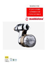
microCLIMA<br />
Compact <strong>coaxial</strong> heat meter<br />
DE-07-MI004-PTB001<br />
Installation and Operating Instructions<br />
1 Application and Function<br />
This compact <strong>coaxial</strong> multi-<strong>jet</strong> compact heat meter microCLIMA<br />
is designed for the metering of thermal energy in closed heating<br />
systems.<br />
• The valid standards for the application of heat meters are EN<br />
1434, parts 1 + 6, the Directive 2004/22/EC (‘MID’), in particular<br />
annex MI-004, and the relevant national verification regulations.<br />
• The regulations for electrical installations are to be observed.<br />
• The instrument identification and the seals must not be damaged<br />
or removed – otherwise the guarantee and the approved<br />
application of the instrument no longer apply.<br />
• The measurement stability of the heat meters is only guaranteed<br />
when the quality of the water meets the conditions as specifi ed in<br />
the AGFW Recommendation FW-510.<br />
• The heat meter left the factory in conformance with all applicable<br />
safety regulations. All maintenance and repair work is to be carried<br />
out only by qualifi ed and authorized technical personnel.<br />
• The instrument must be stored and transported at above-freezing<br />
temperatures. The storage and/or ambient temperature must not<br />
fall below 5°C.<br />
• All details and specifi cations listed on the data sheet of the heat<br />
meter must be adhered to.<br />
• Instruments with a return-flow temperature sensor mounted directly<br />
in the flow sensor may only be mounted in the return flow.<br />
• The temperature sensor cables must not be kinked, rolled up,<br />
lengthened or shortened.<br />
• To clean the heat meter (only if necessary) use a slightly moist<br />
(not dripping wet!) cloth.<br />
• All electrical connections must be laid at a minimum distance<br />
of 50 cm to sources of electromagnetic interference (switches,<br />
controllers, pumps, etc.). All instrument connections must be laid<br />
at a minimum distance of 10 cm to other current-carrying wires.<br />
• To protect against damage and dirt the heat meter should only be<br />
removed from the packaging directly before installation.<br />
• Important: Instruments with activated radio function<br />
are not allowed on air freight!<br />
<strong>Maddalena</strong> S.p.A., Via G.B. <strong>Maddalena</strong>, 2/4, 33040 Povoletto (UD) - Italy<br />
Phone: +39 0432 634811, Fax.: +39 0432.679007, Fax Export.: +39 0432.679820 , www.maddalena.it<br />
Article-No. 1080100016 - 2012-07-25 - MSH<br />
Pagina/Page 8<br />
• If more than one heat meter is installed in one unit, care must be<br />
taken to ensure that all the meters have the same installation<br />
conditions.<br />
• Pay attention to the installation point of the heat meter:<br />
standard: in the return fl ow pipe<br />
optional: in the forward flow pipe (state when ordering)<br />
• The direct-mounted temperature sensor or the plug on the<br />
temperature sensor installation point may not be altered in any way,<br />
in particular the sealing wire must not be removed.<br />
• In the case of instruments with a temperature sensor mounted in<br />
the fl ow sensor (non-symmetrical installation) the limitation of the<br />
minimal flow (q ≥ 24 l/h or q ≥ 50 l/h) indicated on the<br />
identification plate must be observed.<br />
• Categorically, all temperature sensors which are not mounted in the<br />
flow sensor must be direct-mounted in the pipe.<br />
• The single pipe connection piece (EAS) should correspond to<br />
the following table: „Installation in Single Pipe Connection Pieces<br />
(EAS)“.<br />
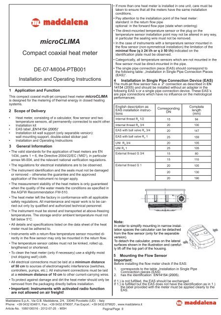
4 Installation in Single Pipe Connection Device (EAS)<br />
The multi-<strong>jet</strong> fl ow sensor has a 2“ connection as described in EN<br />
14154 (2005) and should be installed without an adapter in the<br />
following EAS´s or a single pipe connection device. These EAS´s<br />
are pipe connections which have no infl uence on the metrological<br />
performances:<br />
English description as<br />
EAS installation instructions<br />
Corresponding<br />
DN<br />
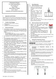
5 Mounting the Flow Sensor<br />
Important:<br />
Before installing the flow meter check if the EAS:<br />
Complete<br />
length<br />
(mm)<br />
Internal thread R p<br />
1/2 15 94<br />
Internal thread R P<br />
3/4 20 100<br />
EAS with ball valve R P<br />
3/4 20 147<br />
EAS with ball valve R P<br />
1 25 159<br />
UNI R P<br />
3/4 20 105<br />
UNI R P<br />
1 25 105<br />
External thread G 3/4 15 80<br />
15 110<br />
External thread G 1 20 105<br />
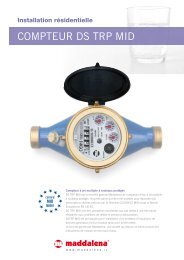
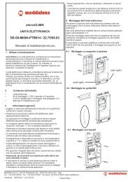
Note:<br />
In order to simplify mounting in narrow installation<br />
spaces the calculator can be detached<br />
from the fl ow sensor (only for the separable<br />
version).<br />
To detach the calculator, press on the lateral<br />
surfaces shown in the illustration and carefully<br />
lift off the top part of the housing.<br />
20 130<br />
20 190<br />
1. corresponds to the table „Installation in Single Pipe<br />
Conncection pieces (EAS)<br />
2. has the identifi cation EN14154 (2005).<br />
If 1.) is not fulfi lled, the EAS should be exchanged.<br />
If 1.) is fulfilled but the EAS does not have the identifi cation as in 1.)<br />
the label provided with the meter must be applied clearly to the<br />
EAS.