Manuel d'installation - jet multiple coaxial - Maddalena
Manuel d'installation - jet multiple coaxial - Maddalena
Manuel d'installation - jet multiple coaxial - Maddalena

You also want an ePaper? Increase the reach of your titles
YUMPU automatically turns print PDFs into web optimized ePapers that Google loves.
2 Contenuto dell’imballo<br />
3 Informazioni generali<br />
microCLIMA<br />
Misuratore di calorie<br />
compatto coassiale<br />
DE-07-MI004-PTB001<br />
Manuale di installazione e uso<br />
1 Utilizzo e funzionamento<br />
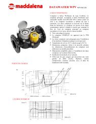
Il calorimetro compatto coassiale a getto multiplo microCLIMA è<br />
concepito per la misurazione del consumo dell’energia termica negli<br />
impianti di riscaldamento a circuito chiuso.<br />
• Calorimetro composto da: unità elettronica, misuratore<br />
di volume, due sensori di temperatura.<br />
• Kit per l‘installazione<br />
• Etichetta di conformità alla norma EN 14154 (2005)<br />
• Kit per il montaggio su parete (solo per la versione separabile):<br />
staffa ed etichetta biadesiva<br />
• Manuale di installazione e uso<br />
Leggere e osservare attentamente i punti e le specifi che di questo<br />
manuale.<br />
• Normative vigenti per l’utilizzo del calorimetro: norma EN 1434,<br />
parti 1 e 6; Direttiva 2004/22/CE, Allegati I e MI-004; relative<br />
normative metrologiche nazionali.<br />
• Osservare le prescrizioni relative all’installazione delle<br />
apparecchiature elettriche.<br />
• Per garantire la durata e il corretto funzionamento dello<br />
strumento, la composizione dell’acqua deve essere conforme alla<br />
direttiva FW-510 emanata dall’associazione tedesca AGFW<br />
(Arbeitsgemeinschaft für Wärme und Heizkraftwirtschaft).<br />
• I sigilli dello strumento non devono essere danneggiati o rimossi.<br />
In caso contrario, decadono la garanzia e la validità della verifica<br />
prima.<br />
• Lo strumento esce dalla fabbrica funzionante, in perfetto stato e<br />
conforme alle normative sulla sicurezza.<br />
• Per garantire l’integrità dello strumento, estrarlo dal suo imballo<br />
solo al momento dell’installazione.<br />
• Le operazioni di montaggio, manutenzione e riparazione devono<br />
essere effettuate esclusivamente da personale specializzato.<br />
• Pulire lo strumento solo se necessario utilizzando un panno<br />
inumidito con acqua.<br />
• Immagazzinare e trasportare lo strumento a una temperatura<br />
superiore a 5 °C.<br />
• Rispettare le condizioni di montaggio. Lo standard prevede<br />
l’installazione sul circuito di ritorno; è disponibile una versione<br />
opzionale per l’installazione sul circuito di ingresso.<br />
• Se lo strumento è dotato di sensore temperatura di ritorno<br />
integrato deve essere installato sul circuito di ritorno.<br />
• Una volta installati (installazione bagnata), il sensore di<br />
temperatura e il dado di chiusura non devono essere alterati<br />
e il sigillo non deve essere rimosso.<br />
• Importante: gli strumenti con interfaccia radio attiva non<br />
sono ammessi in aereo.<br />
• Non attorcigliare, allungare o accorciare i cavi delle sonde di<br />
temperatura.<br />
• Nel caso di strumenti con sensore di temperatura integrato nel<br />
misuratore di volume, rispettare il valore minimo della portata<br />
indicato sull’etichetta dello strumento: q ≥ 24 l/h / q ≥ 50 l/h.<br />
Attenzione: per il sensore di temperatura è necessaria<br />
l’installazione diretta (bagnata) nel circuito di ingresso.<br />
• In caso di installazione di più contatori nella stessa unità<br />
assicurarsi che le condizioni di installazione siano le medesime<br />
per ciascuno strumento.<br />
• I cavi devono essere mantenuti a una distanza minima di<br />
50 cm da fonti di interferenza elettromagnetica (interruttori,<br />
regolatori, pompe, etc.) e a una distanza minima di 10 cm<br />
da altri cavi elettrici.<br />
• Il dispositivo di connessione (EAS) deve essere conforme ai<br />
parametri riportati nella seguente tabella.<br />
4 Installazione in dispositivo di connessione (EAS)<br />
Il misuratore di volume è dotato di una connessione da 2” come<br />
prescritto dalla norma EN 14154 (2005) e non necessita di alcun<br />
adattatore per l’installazione nelle seguenti versioni di dispositivi di<br />
connessione (EAS) o in altri dispositivi compatibili in termini<br />
metrologici. Le versioni riportate di seguito non influenzano le<br />
prestazioni metrologiche dello strumento.<br />
Descrizione<br />
DN<br />
corrispondente<br />
Lunghezza<br />
totale<br />
mm<br />
Filetto interno R p<br />
1/2 15 94<br />
Filetto interno R P<br />
3/4 20 100<br />
EAS con valvola a sfera<br />
R P<br />
3/4<br />
20 147<br />
EAS con valvola a sfera R P<br />
1 25 159<br />
UNI R P<br />
3/4 20 105<br />
UNI R P<br />
1 25 105<br />
Filetto esterno G 3/4 15 80<br />
15 110<br />
Filetto esterno G 1 20 105<br />
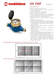
Attenzione:<br />
Per facilitare il montaggio in spazi ridotti o<br />
poco agevoli, l’unità elettronica può essere<br />
separata dal misuratore di volume (solo per<br />
la versione separabile).<br />
Per rimuovere l’unità elettronica premere<br />
ai lati come indicato in fi gura e sollevare la<br />
parte superiore.<br />
5 Montaggio del misuratore di volume<br />
20 130<br />
20 190<br />
Prima di procedere all’installazione verificare quanto segue:<br />
• il dispositivo di connessione deve essere certificato secondo<br />
quanto indicato nella tabella di pagina 2<br />
• il dispositivo deve riportare l’indicazione di conformità alla norma<br />
EN 14154 (2005)<br />
Se il dispositivo è certificato, ma non riporta l’indicazione di<br />
certificazione di conformità, è necessario apporvi l’etichetta inclusa<br />
nella confezione (vedi pag. 1 Contenuto dell’imballo). Se non è<br />
certificato, deve essere sostituito.<br />
<strong>Maddalena</strong> S.p.A., Via G.B. <strong>Maddalena</strong>, 2/4, 33040 Povoletto (UD) - Italy<br />
Phone: +39 0432 634811, Fax.: +39 0432.679007, Fax Export.: +39 0432.679820 , www.maddalena.it<br />
Article-No. 1080100016 - 2012-07-25 - MSH<br />
Pagina/Page 1
Per installare il misuratore di volume procedere come indicato di<br />
seguito:<br />
– Chiudere le valvole<br />
– Svuotare il tratto di tubo che è stato chiuso<br />
– In caso di sostituzione del misuratore, smontare i sensori di<br />
temperatura<br />
– Rimuovere il tappo di chiusura o il contatore da sostituire dal<br />
dispositivo di connessione<br />
– Rimuovere la guarnizione, verifi care l’integrità della superficie<br />
e, se necessario, pulirla.<br />
– Posizionare la nuova guarnizione<br />
sul dispositivo di connessione,<br />
mantenendo la superficie piana<br />
verso l’alto.<br />
– Utilizzare del grasso siliconico<br />
per lubrificare la fi lettatura del<br />
misuratore di volume.<br />
– Verifi care il corretto<br />
posizionamento dell’OR.<br />
– Avvitare il misuratore dapprima a mano e quindi avvitare fino al<br />
completo arresto con l’ausilio di una chiave.<br />
6 Montaggio dei sensori di temperatura<br />
Per le tubazioni con diametro inferiore a DN 25, la normativa<br />
prevede in caso di installazione di nuovi impianti o sostituzione di<br />
impianti obsoleti il montaggio dei sensori di temperatura in valvola<br />
portasonda.<br />
• Il sensore di temperatura con etichetta rossa deve essere<br />
installato sul circuito di ingresso.<br />
• Il sensore di temperatura con etichetta blu deve essere<br />
installato sul circuito di ritorno.<br />
Installazione in valvola a sfera e in raccordo TEE<br />
• Rimuovere i tappi/la sonda da sostituire e la<br />
guarnizione/il vecchio OR. Pulire le superfici per<br />
eliminare eventuali residui.<br />
• Rimuovere l’OR dalla sonda e posizionarlo nella<br />
fi lettatura della valvola a sfera/del raccordo TEE.<br />
• Regolare la profondità di immersione della sonda<br />
per mezzo dell’apposito nipplo.<br />
• Inserire la sonda nella valvola a sfera/nel raccordo<br />
TEE assicurandosi che non tocchi il fondo:<br />
la sonda deve raggiungere la mezzeria della<br />
tubazione.<br />
• Serrare fino all’arresto.<br />
7 Messa in funzione<br />
• Riaprire lentamente le valvole.<br />
• Verifi care la tenuta e il funzionamento.<br />
Dopo aver verificato il corretto funzionamento del sistema,<br />
applicare i sigilli ai sensori di temperatura e all’unità elettronica.<br />
In caso di sostituzione del contatore, annotarne la lettura e il<br />
numero di serie.<br />
Verificare inoltre che:<br />
• Il sistema di riscaldamento sia in funzione<br />
• Le valvole di chiusura siano aperte<br />
• Le tubazioni non siano intasate e il fi ltro sia pulito<br />
• Siano stati applicati i sigilli ai sensori di temperatura<br />
• La freccia sul misuratore di volume indichi la direzione corretta<br />
• Lo strumento visualizzi il volume istantaneo<br />
• Venga visualizzata una differenza di temperatura verosimile<br />
• Il sensore di temperatura con etichetta rossa sia installato nel<br />
circuito di ingresso.<br />
• Il sensore di temperatura con etichetta blu sia installato nel<br />
circuito di ritorno.<br />
• Negli strumenti con sensore di temperatura di ritorno integrato, il<br />
misuratore di volume deve essere installato sul circuito di ritorno.<br />
8 Unità elettronica<br />
L’unità elettronica è dotata di un display a cristalli liquidi a 8<br />
caratteri e alcuni simboli speciali.<br />
I dati sono organizzati su tre livelli e possono essere visualizzati<br />
per mezzo del tasto posizionato sotto al display. La visualizzazione<br />
standard propone il consumo totale di energia dalla messa in<br />
funzione dello strumento.<br />
Premendo brevemente il tasto si scorrono le informazioni di<br />
ciascuno livello.<br />
Il livello principale viene visualizzato automaticamente per primo.<br />
Premendo il tasto per più di 4 secondi, si scorrono i vari livelli.<br />
Per visualizzare il livello desiderato, rilasciare il tasto.<br />
Dopo un minuto di non utilizzo, ricompare la visualizzazione<br />
standard.<br />
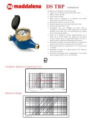
1. Livello principale<br />
1.) Consumo totale<br />
energia in MWh<br />
(visualizzazione<br />
standard)<br />
4). Volume totale<br />
in m 3<br />
6.) Portata istantanea<br />
in m 3 /h<br />
2.)Test di funzionamento<br />
del display. Tutti<br />
i segmenti devono<br />
essere visualizzati<br />
contemporaneamente<br />
5.) Potenza istantanea<br />
in kW<br />
7.) Data corrente<br />
Solo in strumenti con due ingressi impulsi!<br />
9. )Registro tariffa 1: valori alternati<br />
al registro e ai parametri 2)<br />
11.) Lettura istantanea del conteggio<br />
impulsi 1, alternata al valore<br />
impulsi. 2)<br />
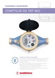
2. Livello tecnico<br />
1.) Potenza massima<br />
in kW<br />
4.) Temperatura in<br />
uscita in o C<br />
7.) Valore impulso/<br />
litro<br />
10.) Versione firmware/software<br />
2.) Portata massima<br />
in m 3 /h<br />
5.) Differenza di<br />
temperatura<br />
3.) Valore di lettura a<br />
una data prefissata. Il<br />
valore si alterna con<br />
la data stessa 1)<br />
8.) Messaggio di errore (visualizzazione<br />
binaria ed esadecimale<br />
alternata<br />
10.) Registro tariffa 2: valori<br />
alternati al registro e ai<br />
parametri 2)<br />
12.) Lettura istantanea del conteggio<br />
impulsi 2, alternata al valore<br />
impulsi. 2)<br />
3.)Temperatura in<br />
ingresso in o C<br />
6.) Giorni di funzionamento<br />
dalla<br />
taratura<br />
8.) Indirizzo M-bus 9.) Numero di<br />
matricola<br />
<strong>Maddalena</strong> S.p.A., Via G.B. <strong>Maddalena</strong>, 2/4, 33040 Povoletto (UD) - Italy<br />
Phone: +39 0432 634811, Fax.: +39 0432.679007, Fax Export.: +39 0432.679820 , www.maddalena.it<br />
Article-No. 1080100016 - 2012-07-25 - MSH<br />
Pagina/Page 2
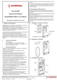
3. Livello statistico<br />
1) Data della lettura precedente<br />
alternata con il relativo valore.<br />
Se impostati, è possibile visualizzare<br />
il volume totale, i valori<br />
tariffari o i valori di<br />
ciascuno strumento collegato<br />
agli ingressi impulsi opzionali. 1)<br />
1)<br />
Fino alla fine del mese, il dato di consumo e la data sono visualizzati a 0.<br />
2)<br />
Può essere impostato con l’apposito software. E’ necessaria una password che<br />
può essere richiesta al fornitore.<br />
9 Interfacce e opzioni<br />
2-16) Letture mensili: data<br />
alternata al relativo valore. Se<br />
impostati, è possibile<br />
visualizzare il volume totale,<br />
i valori tariffari o i valori di<br />
ciascun contatore impulsi 1)<br />
9.1 Interfaccia ottica a infrarossi<br />
Per il trasferimento dei dati dal calorimetro al computer è<br />
necessaria una testina ottica che andrà collegata a quest’ultimo.<br />
La testina ottica e il software necessario vengono forniti su<br />
richiesta.<br />
L’interfaccia ottica (a infrarossi) si attiva premendo l’apposito<br />
tasto sullo strumento. Se dopo 60 secondi non viene ricevuto un<br />
“telegramma” valido o se il tasto non viene premuto nuovamente,<br />
l’interfaccia si disattiva. L’interfaccia ottica è alimentata da<br />
batteria.<br />
9.2. M-Bus (disponibile su richiesta)<br />
9.2.1 Versione con alimentazione da M-Bus<br />
In questa esecuzione, l’interfaccia M-bus fornisce l’alimentazione<br />
all’unità elettronica (versione senza separazione galvanica)<br />
rendendo illimitato il numero delle letture per ogni strumento.<br />
L’interfaccia è conforme ai requisiti del PTB sull’immunità alle<br />
interferenze, garantendo così la sicurezza dei dati trasmessi.<br />
9.2.2 Versione senza alimentazione da M-Bus<br />
(con separazione galvanica)<br />
Questa versione non è alimentata dall’interfaccia M-Bus, pertanto<br />
il numero di richieste che può essere inviato a uno strumento è<br />
limitato.<br />
In una rete M-bus con un massimo di 250 strumenti, è possibile<br />
effettuare 24 richieste al giorno per ciascuno strumento. Se il<br />
numero di letture effettuate e/o degli strumenti connessi è minore,<br />
le richieste inutilizzate verranno immagazzinate.<br />
9.2.3 Osservazioni generali sull’M-Bus<br />
• L’interfaccia ottica è alimentata dalla batteria e quindi il<br />
numero di letture giornaliere è limitato.<br />
• Durante la comunicazione via M-Bus, le altre interfacce (tasto<br />
e interfaccia ottica) dello strumento non sono utilizzabili.<br />
• Il protocollo M-Bus è conforme alle norme EN 13757-2, EN<br />
13757-3, EN 1434-3 e alla Raccomandazione sull’M-Bus<br />
(Versione 4.8 del novembre 1997) – protocollo IEC 870 parti<br />
1, 2 e 4.<br />
• Ogni unità elettronica non sopporta una tensione superiore<br />
a quella consentita dalla tensione bus (± 50 V). Utilizzare un<br />
level converter come ulteriore misura di protezione.<br />
• L’installazione degli strumenti in una rete M-Bus deve essere<br />
effettuata esclusivamente da personale specializzato.<br />
• Assicurarsi che la struttura della rete M-bus (lunghezza e<br />
diametro dei cavi) sia compatibile con la velocità di<br />
trasmissione (2400 Baud) dello strumento collegato.<br />
9.3 Uscita impulsi (contatto a potenziale libero)<br />
L’uscita impulsi a potenziale libero è disponibile su richiesta. Si<br />
tratta di un interruttore elettronico (classe OA, standard EN 1434)<br />
attraverso il quale vengono emessi gli impulsi. L’uscita impulsi si<br />
chiude, corrispondentemente al valore impulsi (si veda il valore<br />
indicato sullo strumento), per un periodo di 125 ms.<br />
Se nel corso di una misurazione vengono emessi più impulsi,<br />
l’intervallo tra due impulsi sarà comunque di 125 ms. L’utente può<br />
utilizzare liberamente il segnale nel rispetto dei valori massimi di<br />
carico previsti.<br />
Alle uscite impulsi possono essere collegati diversi strumenti.<br />
Valore impulsi:<br />
Calorie: 1kWh/imp. o altri valori su richiesta<br />
Volume: 100 l/imp.<br />
Uscita impulsi:<br />
Corrente massima di commutazione 300 mA ~/-<br />
Tensione massima di commutazione 35 V ~/-<br />
Potenza massima di commutazione<br />
Resistenza di isolamento<br />
Resistenza di contatto<br />
Capacitá<br />
Corrente massima<br />
300 mW<br />
> 10 09 Ohm<br />
max. 25 Ohm<br />
1.5 pF<br />
120 mA<br />
Rigiditá dielettrica (contatto aperto) 350 V ~/-<br />
Durata impulso<br />
Intervallo minimo tra impulsi<br />
9.4 Configurazione del data logger<br />
125 ms<br />
125 ms<br />
La funzione data logger viene fornita su richiesta.<br />
Il data logger memorizza il consumo e le singole letture a intervalli di<br />
tempo impostabili dall’utente.<br />
I dati possono essere salvati in diversi formati per poi essere utilizzati<br />
per l’analisi e la gestione dei consumi.<br />
La lettura dei dati può essere effettuata sia via interfaccia ottica sia<br />
via M-Bus.<br />
Il data logger funziona come memoria circolare, ovvero i valori<br />
correnti sono sempre disponibili e, quando non vi è più spazio nella<br />
memoria, il dato meno recente viene sovrascritto.<br />
La capacità della memoria è di ca. 10.589 stringhe dati.<br />
Il software effettua la lettura di un contatore alla volta che può essere<br />
interrogato attraverso l’indirizzo primario o secondario. Se nella<br />
rete è presente un solo contatore, si può utilizzare l’indirizzo 254.<br />
I seguenti valori possono essere impostati per mezzo del software<br />
(singolarmente o tutti):<br />
• Ora (viene sempre memorizzata)<br />
• Calorie<br />
• Frigorie<br />
• Volume<br />
• Potenza<br />
• Portata<br />
• Teperatura di andata<br />
• Temperatura di ritorno<br />
• Differenza di temperatura<br />
Cavo consigliato:<br />
cavo telefonico J-Y (ST) Y2 x 2 0,8 mm²<br />
<strong>Maddalena</strong> S.p.A., Via G.B. <strong>Maddalena</strong>, 2/4, 33040 Povoletto (UD) - Italy<br />
Phone: +39 0432 634811, Fax.: +39 0432.679007, Fax Export.: +39 0432.679820 , www.maddalena.it<br />
Article-No. 1080100016 - 2012-07-25 - MSH<br />
Pagina/Page 3
L’intervallo di tempo della lettura può essere impostato a scelta:<br />
• 1 minuto<br />
• 10 minuti<br />
• 15 minuti<br />
• 30 minuti<br />
• 60 minuti<br />
• 3 ore<br />
• 6 ore<br />
• 12 ore<br />
• 24 ore<br />
In relazione alla confi gurazione, il data logger memorizza da 2117 a<br />
10589 stringhe dati.<br />
Importante<br />
Qualora i parametri vengano reimpostati, i dati memorizzati<br />
andranno persi.<br />
9.5 Mini-Bus<br />
L’interfaccia Mini-Bus è un’interfaccia protettiva (non viene<br />
infl uenzata da segnali esterni) e viene fornita su richiesta.<br />
Consiste in un collegamento a due conduttori a un’interfaccia<br />
induttiva esterna con estensione massima di 50 m. La<br />
comunicazione è di tipo “punto a punto” secondo la norma<br />
EN 1434-3.<br />
Baudrate: 2400 Baud (anche per l’interfaccia ottica).<br />
9.6.1 Configurazione della funzione radio<br />
Lo strumento viene fornito con la funzione radio disattivata<br />
(v. cap. 9.6.2 Attivazione dell’interfaccia radio).<br />
Parametro Opzioni impostazioni Impostazioni<br />
standard<br />
Modalità<br />
S1/T1: unidirezionale<br />
S2/T2: bidirezionale<br />
T1 (unidirezionale)<br />
Trasmissione 00:00 – 24:00 7:00 – 19:00<br />
Intervallo di<br />
trasmissione<br />
Giorni della<br />
settimana<br />
Settimane di<br />
calendario<br />
120 secondi – 240 minuti;<br />
impostazione speciale:<br />
mensile<br />
Lunedì – domenica<br />
1 – 4 1 – 4<br />
120 secondi<br />
Mesi 1 – 12 1 – 12<br />
Data di<br />
accensione<br />
Crittografi a AES<br />
Tipo telegramma<br />
Lunedì - venerdì<br />
01.01 – 31.12 Non impostata<br />
Attivata/non attivata;<br />
stessa chiave per cliente o<br />
ordine/chiave casuale per<br />
contatore<br />
Telegramma breve/<br />
telegramma lungo (valori<br />
mensili);<br />
Attivata; chiave<br />
casuale per<br />
contatore<br />
Telegramma lungo<br />
(valori mensili)<br />
9.6.2 Attivazione dell’interfaccia radio<br />
Lo strumento esce dalla fabbrica con la funzione radio disattivata.<br />
L’attivazione può essere effettuata in due modi:<br />
9.6 Trasmissione via radio<br />
I calorimetri microCLIMA possono essere dotati, su richiesta, di<br />
un’interfaccia radio conforme alla Norma europea EN 13757-4 relativa<br />
alla comunicazione wireless M-Bus.<br />
Frequenza di funzionamento: 868 MHz<br />
Potenza di trasmissione: fino a 25 mW<br />
Protocollo: wireless M-Bus secondo la Norma EN 13757-4; modalità<br />
di funzionamento: T1, S1, T2, S2 a scelta.<br />
Telegramma breve per sistemi fissi di lettura.<br />
Telegramma lungo per lettura con sistema walk by.<br />
Lo strumento viene impostato in fabbrica con l’ora solare (GMT+1).<br />
Si prega di notare quanto segue:<br />
Ora di accensione di riferimento: 7:00<br />
Ora di spegnimento di riferimento: 19:00<br />
a) senza l’ausilio del software: mantenere premuto il tasto di<br />
selezione per più di tre secondi dalla voce “M-bus address”<br />
del Livello 2 – tecnico (v. cap. 8 Unità elettronica).<br />
Le impostazioni di fabbrica verranno quindi caricate:<br />
b) per mezzo del software Device Monitor (disponibile su<br />
richiesta).<br />
La procedura di attivazione della funzione radio per mezzo del<br />
software è descritta nel manuale di istruzioni.<br />
9.6.3 Come verificare che la funzione radio sia<br />
stata attivata<br />
Se la funzione radio è stata attivata correttamente, verrà<br />
visualizzato un triangolo nell’angolo in basso a sinistra del display.<br />
Impostazioni con l’ora solare in corso:<br />
Ora di accensione: 7:00<br />
Ora di spegnimento: 19:00<br />
Impostazioni con l’ora legale in corso:<br />
Ora di accensione: 8:00<br />
Ora di spegnimento: 20:00<br />
Nota:<br />
I calorimetri radio non devono essere installati dietro o tra le<br />
tubazioni del sistema di riscaldamento poiché il segnale potrebbe<br />
venire disturbato. La presenza di altri strumenti dotati di interfacce<br />
radio quali router WLAN, telecomandi etc. potrebbe creare<br />
interferenze. Infine, anche la struttura dell’edificio nel quale lo<br />
strumento è installato, potrebbe influenzarne il funzionamento.<br />
<strong>Maddalena</strong> S.p.A., Via G.B. <strong>Maddalena</strong>, 2/4, 33040 Povoletto (UD) - Italy<br />
Phone: +39 0432 634811, Fax.: +39 0432.679007, Fax Export.: +39 0432.679820 , www.maddalena.it<br />
Article-No. 1080100016 - 2012-07-25 - MSH<br />
Pagina/Page 4
9.7 Impostazione dei due ingressi impulsi aggiuntivi<br />
(solo con M-Bus o interfaccia radio)<br />
Gli ingressi impulsi 1 + 2 permettono di effettuare la lettura via M-bus<br />
di strumenti dotati di uscita impulsi. I parametri (valore impulsi, unità<br />
di misura) possono essere impostati con l’apposito software.<br />
I valori impostabili dipendono dal valore degli impulsi in ingresso e<br />
dall’unità di misura.<br />
• Ingressi impulsi conformi alla norma EN 1434-2:2007, classe IB<br />
• Durata impulso: ≥ 100 ms<br />
• Frequenza impulso: ≤ 5Hz<br />
• Assorbimento di corrente ≤ 0,1 mA<br />
Valori impostabili:<br />
Valore impulso<br />
Unità di misura<br />
1 litri/kWh per impulso<br />
2,5 litri/kWh per impulso<br />
10 litri/kWh per impulso<br />
25 litri/kWh per impulso<br />
100 litri/kWh per impulso<br />
250 litri/kWh per impulso<br />
1000 litri/kWh per impulso<br />
Installazione degli ingressi impulsi:<br />
• Negli emettitori impulsi con uscita open collector è necessario<br />
rispettare la polarità. Durante l’installazione i conduttori non<br />
devono entrare in contatto l’uno con l’altro per evitare che lo<br />
strumento registri gli impulsi.<br />
• Durante l’installazione del contatore azzerare, se necessario, la<br />
lettura degli strumenti collegati e il valore impulsi<br />
utilizzando il software.<br />
9.7.1 Collegamenti a 6 conduttori (lunghezza cavo: 1 m)<br />
Conduttore<br />
Colore<br />
1 bianco IE1 +<br />
2 marrone IE1 ┴<br />
3 verde IE2 ┴<br />
4 giallo IE2 +<br />
5 grigio M-Bus<br />
6 rosa M-Bus<br />
IE = Ingresso impulsi<br />
1 2 3 4 5 6<br />
9.7.2 Collegamenti per cavi a quattro conduttori<br />
(lunghezza cavo: 1 m) - solo con wireless M-Bus (radio)<br />
Conduttore<br />
Colore<br />
1 giallo IE1+<br />
2 verde IE1┴<br />
3 marrone IE2┴<br />
4 bianco IE2+<br />
1 2 3 4<br />
9.7.3 Impostazione del registro tariffa (disponibile solo per la versione con due ingressi impulsi)<br />
Sono disponibili due registri tariffa per la totalizzazione, in base ai parametri stabiliti, dell’energia o del tempo. I registri possono essere<br />
impostati per mezzo dell’apposito software e possono essere visualizzati sul display o scaricati su PC.<br />
Esempio di visualizzazione Esempio di descrizione Registro tariffa 1<br />
(per la misurazione dell’energia o del tempo)<br />
0 Non defi nito (Impostazione di fabbrica).<br />
1 Energia (0,683 MWh) misurata dalle 18.00 alle 6.00 (impostabile<br />
con intervalli di 10 minuti)<br />
2 Energia (0,683 MWh) misurata nel periodo in cui la potenza<br />
scambiata è stata ≥ 2.000 kW<br />
3 Energia (0,683 MWh) misurata nel periodo in cui la potenza<br />
scambiata è stata ≤ 2.000 kW<br />
4 Energia (0,683 MWh) misurata nel periodo in cui la portata è<br />
stata ≥ 0,600 m 3 /h<br />
5 Energia (0,683 MWh) misurata nel periodo in cui la portata è<br />
stata ≤ 0,600 m 3 /h<br />
6 Tempo (11 h) con temperatura in ingresso<br />
≥ 65 o C (intervalli di 0,01 °C)<br />
7 Tempo (11 h) con temperatura in ingresso<br />
≤ 65 o C (intervalli di 0,01 °C)<br />
8 Tempo (11 h) con temperatura di ritorno<br />
≥ 36 o C (intervalli di 0,01 °C)<br />
9 Tempo (11 h) con temperatura di ritorno<br />
≤ 36 o C (intervalli di 0,01 °C)<br />
10 Energia (0,683 MWh) misurata con differenza di temperatura<br />
≥ 10 o C (intervalli di 0,01 K)<br />
11 Tempo (11 h) in cui la differenza di temperatura è stata<br />
≤ 10 o C (intervalli di 0,01 K)<br />
<strong>Maddalena</strong> S.p.A., Via G.B. <strong>Maddalena</strong>, 2/4, 33040 Povoletto (UD) - Italy<br />
Phone: +39 0432 634811, Fax.: +39 0432.679007, Fax Export.: +39 0432.679820 , www.maddalena.it<br />
Article-No. 1080100016 - 2012-07-25 - MSH<br />
Pagina/Page 5
10 Dati tecnici<br />
Certificazioni<br />
Attestato di esame CE del tipo<br />
DE-07-MI004-PTB001<br />
11 Codici di errore<br />
Quando lo strumento rileva un errore, viene visualizzato<br />
questo simbolo.<br />
Classe di accuratezza 1) EN 1434-1:2007, classe 2/3<br />
Portata minima 1) q i<br />
/q p<br />
Misuratore di volume<br />
orizzontale<br />
verticale<br />
Portata massima q s<br />
/q p<br />
2:1<br />
Classe di protezione<br />
Classe elettromagnetica<br />
Classe meccanica<br />
Classe di disturbo idraulico<br />
Unitá elettronica<br />
Portata nominale q p<br />
m³/h 0,6 1,5 2,5<br />
Portata massima q s<br />
1)<br />
m³/h 1,2 3,0 5,0<br />
Perdita di carico ∆p a q p<br />
mbar 120 225 240<br />
PN bar 16<br />
1:100 / 1:50 / 1:25<br />
IP54<br />
Classe E1<br />
Classe M1<br />
Temperatura di immagazzinaggio<br />
°C +5 °C ... +55 °C<br />
Range di misurazione °C +1 °C ... +150 °C<br />
Differenza di temperatura K 3K ... 100K<br />
standard Batteria litio 3V<br />
Alimentazione<br />
Batteria litio 3V + M-Bus<br />
opzionale<br />
Large battery<br />
Durata batteria 6 anni + 1 / 10 anni + 1<br />
Memorizzazione dati giornaliera / E 2 PROM<br />
Display<br />
LCD a 8-cifre + caratteri<br />
speciali<br />
Interfacce<br />
MAP bar 25<br />
orizzontale<br />
2,5 3,5 4,0<br />
Sensibilitá<br />
l/h<br />
verticale 3,0 5,0 6,0<br />
Soglia di minima portata l/h 1,8 2,0 2,2<br />
Filettature 2“<br />
Range di misurazione<br />
temperatura<br />
°C +15 °C .....+ 90 °C<br />
Installazione<br />
orizzontale; verticale<br />
1)<br />
La classe di precisione e la portata minima sono indicate sullo strumento.<br />
Sensori di temperatura<br />
standard<br />
opzionale<br />
U0<br />
Ottica a infrarossi<br />
M-Bus, M-Bus-VS, uscita<br />
impulsi, Mini-Bus, 2 ingressi<br />
impulsi aggiuntivi (versione<br />
M-Bus-VS),<br />
Radio 868 MHz<br />
Modello PT500<br />
Resistenza di precisione in<br />
platino<br />
Collegamento<br />
2 fili conduttori<br />
Diametro mm 5 mm (opzionale 5,2 o 6 mm)<br />
Lunghezza cavo m 1,5 (opzionale 3,0)<br />
L’errore può essere visualizzato alla posizione 8 del livello<br />
principale anche in forma binaria.<br />
Lo strumento rileva sette diverse tipologie di errore che possono<br />
verificarsi anche congiuntamente.<br />
Codice binario<br />
Descrizione dell’errore<br />
Codice<br />
esadecimale<br />
1 nella posizione 1 Errore check sum error 40<br />
1 nella posizione 2 Errore E 2 PROM error 20<br />
1 nella posizione 3 Reset error 10<br />
1 nella posizione 4 Errore bobina error 08<br />
1 nella posizione 5 Errore sensore riferimento error 04<br />
1 nella posizione 6 Errore sensore temperatura<br />
ritorno o sensore non<br />
collegato<br />
1 nella posizione 7 Errore sensore temperatura<br />
ingresso o sensore non<br />
collegato<br />
error 02<br />
error 01<br />
In caso di errore , con eccezione del Reset, si consiglia di<br />
sostituire lo strumento e inviarlo al fornitore per i controlli<br />
necessari.<br />
Esempio: errore bobina<br />
Errore<br />
Codice<br />
errore<br />
Codice<br />
binario<br />
Errore Check sum<br />
Errore E 2 PROM<br />
Reset<br />
Errore bobina<br />
Errore sensore di riferimento<br />
Errore sensore temperatura ritorno<br />
o sensore non collegato<br />
Errore sensore temperatura ingresso<br />
o sensore non collegato<br />
1 2 3 4 5 6 7<br />
12 Dichiarazione di conformità MID<br />
Codice<br />
esadecimale<br />
Si dichiara che il prodotto descritto in questo manuale è conforme<br />
alle seguenti direttive:<br />
• Direttiva 2004/22/CE del Parlamento Europeo e del Consiglio<br />
del 31 marzo 2004 relativa agli strumenti di misura, Allegati I e<br />
MI-004.<br />
• Direttiva 2004/108/CE del Parlamento Europeo e del Consiglio<br />
del 15 dicembre 2004 relativa alla compatibilità<br />
elettromagnetica.<br />
• Direttiva 2006/95/CE del Parlamento Europeo e del Consiglio<br />
del 12 dicembre 2006 relativa alla bassa tensione.<br />
• Direttiva R&TTE (1999/5/CE)<br />
<strong>Maddalena</strong> S.p.A., Via G.B. <strong>Maddalena</strong>, 2/4, 33040 Povoletto (UD) - Italy<br />
Phone: +39 0432 634811, Fax.: +39 0432.679007, Fax Export.: +39 0432.679820 , www.maddalena.it<br />
Article-No. 1080100016 - 2012-07-25 - MSH<br />
Pagina/Page 6<br />
La dichiarazione di conformità è disponibile sul sito<br />
www.engelmann.de.
Le seguenti istruzioni di montaggio sono valide<br />
solo per la versione separabile<br />
13 Montaggio con supporto a parete<br />
L’unità elettronica può essere separata del misuratore di volume<br />
e può essere fi ssata alla parete per mezzo dell’apposito<br />
supporto. Se possibile, montare il supporto al di sopra del<br />
misuratore di volume.<br />
L’unità elettronica dovrà essere installata in modo tale che il<br />
display sia sempre leggibile e raggiungibile senza ausilii.<br />
B. Montaggio con tasselli*<br />
Premere leggermente ai lati come indicato in fi gura e rimuovere la<br />
parte superiore sollevandola.<br />
Kit di montaggio su parete (solo per la versione<br />
separabile) :<br />
1 supporto a parete<br />
1 etichetta biadesiva.<br />
Praticare i fori sulla parete (diametro 6 mm, profonditá 40 mm).<br />
Verificare la lunghezza massima del cavo bianco di collegamento<br />
del misuratore di volume all’unità elettronica.<br />
Fissare il supporto alla parete.<br />
Montare l’unitá elettronica sul supporto.<br />
A. Montaggio con etichetta biadesiva<br />
Premere leggermente ai lati come indicato in figura e rimuovere la<br />
parte superiore sollevandola.<br />
* vis et chevilles ne sont pas.<br />
Fissare il supporto allo strumento.<br />
Rimuovere uno dei due fogli protettivi dall’etichetta biadesiva.<br />
Attaccare l’etichetta biadesiva sul supporto a muro.<br />
Rimuovere l’altro foglio protettivo e posizionare lo strumento nel<br />
punto desiderato esercitando una leggera pressione.<br />
C. Rimozione dell’unità elettronica dalla parete<br />
Far scorrere l’alloggiamento verso l’alto e quindi rimuoverlo.<br />
14 Contatti<br />
<strong>Maddalena</strong> S.p.A.<br />
Via G.B. <strong>Maddalena</strong>, 2/4,<br />
33040 Povoletto (UD)<br />
Italy<br />
Phone: +39 0432 634811<br />
Fax: +39 0432 679007<br />
Fax Export: +39 0432 679820<br />
www.maddalena.it<br />
<strong>Maddalena</strong> S.p.A., Via G.B. <strong>Maddalena</strong>, 2/4, 33040 Povoletto (UD) - Italy<br />
Phone: +39 0432 634811, Fax.: +39 0432.679007, Fax Export.: +39 0432.679820 , www.maddalena.it<br />
Article-No. 1080100016 - 2012-07-25 - MSH<br />
Pagina/Page 7<br />
Salvo modifiche tecniche.<br />
Le batterie esauste, le apparecchiature che non vengono più<br />
utilizzate e i componenti devono essere smaltiti negli appositi<br />
centri di raccolta.
2 Scope of Delivery<br />
• Heat meter, consisting of a calculator, fl ow sensor and two<br />
temperature sensors, all permanently connected to eacht other.<br />
• Installation kit<br />
• EAS label „EN14154 (2005)“<br />
• Installation kit wall support (only separable version):<br />
wall mounting support, double-sided sticker pad<br />
• Installation and Operating Instructions<br />
3 General Information<br />
microCLIMA<br />
Compact <strong>coaxial</strong> heat meter<br />
DE-07-MI004-PTB001<br />
Installation and Operating Instructions<br />
1 Application and Function<br />
This compact <strong>coaxial</strong> multi-<strong>jet</strong> compact heat meter microCLIMA<br />
is designed for the metering of thermal energy in closed heating<br />
systems.<br />
• The valid standards for the application of heat meters are EN<br />
1434, parts 1 + 6, the Directive 2004/22/EC (‘MID’), in particular<br />
annex MI-004, and the relevant national verification regulations.<br />
• The regulations for electrical installations are to be observed.<br />
• The instrument identification and the seals must not be damaged<br />
or removed – otherwise the guarantee and the approved<br />
application of the instrument no longer apply.<br />
• The measurement stability of the heat meters is only guaranteed<br />
when the quality of the water meets the conditions as specifi ed in<br />
the AGFW Recommendation FW-510.<br />
• The heat meter left the factory in conformance with all applicable<br />
safety regulations. All maintenance and repair work is to be carried<br />
out only by qualifi ed and authorized technical personnel.<br />
• The instrument must be stored and transported at above-freezing<br />
temperatures. The storage and/or ambient temperature must not<br />
fall below 5°C.<br />
• All details and specifi cations listed on the data sheet of the heat<br />
meter must be adhered to.<br />
• Instruments with a return-flow temperature sensor mounted directly<br />
in the flow sensor may only be mounted in the return flow.<br />
• The temperature sensor cables must not be kinked, rolled up,<br />
lengthened or shortened.<br />
• To clean the heat meter (only if necessary) use a slightly moist<br />
(not dripping wet!) cloth.<br />
• All electrical connections must be laid at a minimum distance<br />
of 50 cm to sources of electromagnetic interference (switches,<br />
controllers, pumps, etc.). All instrument connections must be laid<br />
at a minimum distance of 10 cm to other current-carrying wires.<br />
• To protect against damage and dirt the heat meter should only be<br />
removed from the packaging directly before installation.<br />
• Important: Instruments with activated radio function<br />
are not allowed on air freight!<br />
<strong>Maddalena</strong> S.p.A., Via G.B. <strong>Maddalena</strong>, 2/4, 33040 Povoletto (UD) - Italy<br />
Phone: +39 0432 634811, Fax.: +39 0432.679007, Fax Export.: +39 0432.679820 , www.maddalena.it<br />
Article-No. 1080100016 - 2012-07-25 - MSH<br />
Pagina/Page 8<br />
• If more than one heat meter is installed in one unit, care must be<br />
taken to ensure that all the meters have the same installation<br />
conditions.<br />
• Pay attention to the installation point of the heat meter:<br />
standard: in the return fl ow pipe<br />
optional: in the forward flow pipe (state when ordering)<br />
• The direct-mounted temperature sensor or the plug on the<br />
temperature sensor installation point may not be altered in any way,<br />
in particular the sealing wire must not be removed.<br />
• In the case of instruments with a temperature sensor mounted in<br />
the fl ow sensor (non-symmetrical installation) the limitation of the<br />
minimal flow (q ≥ 24 l/h or q ≥ 50 l/h) indicated on the<br />
identification plate must be observed.<br />
• Categorically, all temperature sensors which are not mounted in the<br />
flow sensor must be direct-mounted in the pipe.<br />
• The single pipe connection piece (EAS) should correspond to<br />
the following table: „Installation in Single Pipe Connection Pieces<br />
(EAS)“.<br />
4 Installation in Single Pipe Connection Device (EAS)<br />
The multi-<strong>jet</strong> fl ow sensor has a 2“ connection as described in EN<br />
14154 (2005) and should be installed without an adapter in the<br />
following EAS´s or a single pipe connection device. These EAS´s<br />
are pipe connections which have no infl uence on the metrological<br />
performances:<br />
English description as<br />
EAS installation instructions<br />
Corresponding<br />
DN<br />
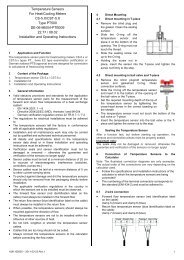
5 Mounting the Flow Sensor<br />
Important:<br />
Before installing the flow meter check if the EAS:<br />
Complete<br />
length<br />
(mm)<br />
Internal thread R p<br />
1/2 15 94<br />
Internal thread R P<br />
3/4 20 100<br />
EAS with ball valve R P<br />
3/4 20 147<br />
EAS with ball valve R P<br />
1 25 159<br />
UNI R P<br />
3/4 20 105<br />
UNI R P<br />
1 25 105<br />
External thread G 3/4 15 80<br />
15 110<br />
External thread G 1 20 105<br />
Note:<br />
In order to simplify mounting in narrow installation<br />
spaces the calculator can be detached<br />
from the fl ow sensor (only for the separable<br />
version).<br />
To detach the calculator, press on the lateral<br />
surfaces shown in the illustration and carefully<br />
lift off the top part of the housing.<br />
20 130<br />
20 190<br />
1. corresponds to the table „Installation in Single Pipe<br />
Conncection pieces (EAS)<br />
2. has the identifi cation EN14154 (2005).<br />
If 1.) is not fulfi lled, the EAS should be exchanged.<br />
If 1.) is fulfilled but the EAS does not have the identifi cation as in 1.)<br />
the label provided with the meter must be applied clearly to the<br />
EAS.
Mounting the Heat Meter in an EAS<br />
– Flush the pipes according to DIN/EN.<br />
– Close the shut-off valves. Drain the closed-off length of pipe.<br />
– Demount the temperature sensor(s).<br />
– Taking into account the direction of flow (EAS)<br />
– Remove the overfl ow fl ange or the old heat meter from the EAS<br />
using a size 22 wrench (SW22).<br />
– Remove all old gaskets. Check sealing surfaces and threads for<br />
imperfections or dirt. If necessary, debur or clean with a suitable<br />
cleansing liquid.<br />
– Place the new profi le gasket in the<br />
EAS with the fl at surface facing up.<br />
– Lubricate the external thread of the<br />
fl ow sensor with a thin layer of food<br />
safe silicon grease.<br />
– Check that the O-ring on the outlet<br />
of the fl ow sensor is in the correct<br />
position.<br />
– Screw in the heat meter tightly<br />
by hand and then tighten additionally<br />
with a suitable wrench to the<br />
mechanical end stop (metal-to-metal).<br />
– Rotate the calculator into the correct reading position.<br />
6 Mounting the Temperature Sensors<br />
For pipe systems of size ≤ DN25 the MID regulations require direct<br />
mounting of the temperature sensors for new installations (new construction,<br />
or retrofi tted heating systems).<br />
Note:<br />
During installation be sure that the return fl ow sensor (blue label) is<br />
mounted in the „colder pipe“ and the forward fl ow sensor (red label)<br />
in the „warmer pipe“.<br />
Direct mounting (ball valve and T-piece)<br />
• Remove the blind plug/old temperature sensor<br />
and gasket/old O-ring. Clean connection surfaces.<br />
• Slide the O-ring off the temperature sensor and<br />
insert it to the bottom of the threaded opening of<br />
the ball valve or the T-piece.<br />
• Set the required mounting depth of the tip of the<br />
temperature sensor by tightening the cross-head<br />
screw in the correct beading on the sheath.<br />
• The temperature sensor must not touch the<br />
bottom of the ball valve or T-piece.<br />
• Insert the temperature sensor into the ball valve or<br />
the T-piece and tighten the screw nut to the stop.<br />
7 Start of Operation<br />
• Slowly open the shut-off valves.<br />
• Check that the meter is functioning properly and that there are<br />
no leaks.<br />
After confi rming that the heat meter is functioning properly, insert and<br />
tighten the sealing wires for the temperature sensors and the flow<br />
sensor itself.<br />
When replacing a meter at the end of a verification period note the<br />
meter readings and the serial numbers of the old and new meters.<br />
Check the following points for the start of operation:<br />
• Is the heat meter of the right size<br />
• Are the shut-off valves open<br />
• Is the heating system clear (dirt filters not clogged)<br />
• Are the temperature sensors an the flow sensor sealed (against<br />
manipulation)<br />
• Is the directional arrow on the flow sensor in the correct<br />
direction<br />
• Is a flow volume displayed<br />
• Is a plausible temperature difference displayed<br />
• For instruments with two external temperature sensors, is the<br />
forward flow sensor (red) in the forward fl ow and the return flow<br />
sensor (blue) in return flow pipe<br />
• For instruments with an integrated return fl ow temperature<br />
sensor, check the fl ow sensor is installed in the return flow.<br />
8 Display<br />
The calculator has a liquid crystal display with 8 digits and special<br />
characters. The values that can be shown are divided into three<br />
display loops. All data is retrieved using the pushbutton next to the<br />
display.<br />
The standard display is the total heat energy consumed since the<br />
meter was put into operation.<br />
At the start you are automatically in the main loop (1 st level). By<br />
pressing the key longer than 4 seconds you change to the next<br />
display loop. Keep the key pressed until you reach the disired<br />
information loop. By pressing the key briefly you can scan all the<br />
information within a loop.<br />
After one minute of non-use of the pushbutton, the display automatically<br />
returns to the main loop.<br />
1. Level / Main Loop<br />
1.) Total heat energy<br />
in MWh<br />
– standard display –<br />
4). Total volume in<br />
m 3<br />
6.) Current flow in<br />
m 3 /h<br />
2.) Segment test, all<br />
segments triggered<br />
simultaneously<br />
5.) Current power<br />
in kW<br />
7.) Current<br />
date<br />
View only for instruments with 2 pulse inputs!<br />
9. )Tariff register1: Values alternating<br />
with tariff register and<br />
criteria 2)<br />
11.) Momentary reading of the<br />
pulse counter1 alternating with<br />
the pulse value. 2)<br />
2. Level / Technician`s Loop<br />
1.) Maximum power<br />
in kW<br />
4.) Return flow<br />
temperature in o C<br />
7.) Pulse value;<br />
pulses per liter<br />
10.) Firmware/Software<br />
version<br />
2.) Maximum flow<br />
in m 3 /h<br />
5.) Temperature<br />
difference<br />
3.) Heat energy at last<br />
billing date alternating<br />
with last billing date 1)<br />
8.) Error message (alternating<br />
binary and hexadecimal display)<br />
10.) Tariff register2: Values<br />
alternating with tariff<br />
register and criteria 2)<br />
12.) Momentary reading of the<br />
pulse counter2 alternating with<br />
the pulse value. 2)<br />
3.)Forward flow<br />
temperature in o C<br />
6.) Days in operation<br />
since verification<br />
8.) M-Bus address 9.) Serial number of<br />
the heat meter<br />
<strong>Maddalena</strong> S.p.A., Via G.B. <strong>Maddalena</strong>, 2/4, 33040 Povoletto (UD) - Italy<br />
Phone: +39 0432 634811, Fax.: +39 0432.679007, Fax Export.: +39 0432.679820 , www.maddalena.it<br />
Article-No. 1080100016 - 2012-07-25 - MSH<br />
Pagina/Page 9
3. Level / Statistics Loop<br />
1.) Previous billing date alternating<br />
with its value. Alternatively,<br />
the total volume, tariff values, or<br />
values of individual instruments<br />
connected to the optional pulse<br />
inputs can be displayed, if so<br />
set. 1)<br />
1)<br />
Up to the end of the month the consuption and reading date for that month will<br />
be shown as 0.<br />
2)<br />
Can be set using the software. A dedicated meter password is necessary.<br />
Password available from manufacturer.<br />
9 Interfaces and Options<br />
9.1 Optical (infrared) interface<br />
In order for a PC to be able to communicate with a<br />
calculator instrument, it is necessary to connect an optocoupler<br />
to the serial or USB interface of the PC. The optocoupler and the<br />
necessary software are available as options. Baudrate (2400 Bd).<br />
The optical infrared interface is activated with the key.<br />
If within 60 seconds neither a valid telegram is received nor the<br />
key pressed again, then the interface is deactivated.<br />
9.2 M-bus (optional)<br />
9.2.1 M-bus with power supply (M-bus VS)<br />
For increased communication, microCLIMA can be<br />
supplied with power via the M-bus interface.<br />
This protective M-bus interface (M-bus VS) is not galvanically<br />
separated. This version M-bus interface allows for an unlimited<br />
number of read-outs per instrument.<br />
9.2.2 M-bus without power supply (M-bus)<br />
With the option ‘M-bus without power supply‘ the protective interface<br />
is galvanically separated. This means that additional power<br />
supply cannot be obtained using the M-bus network.<br />
In a maximum-sized M-bus network of 250 meters, 24 read-outs<br />
per day are possible for each meter. If fewer read-outs are carried<br />
out and/or fewer heat meters are installed in the network (connected<br />
to the M-bus system), the unused amount of available readouts<br />
is stored in the instrument to be used when needed.<br />
9.2.3 General M-bus information<br />
2. - 16.) Monthly values: Dates<br />
alternating with their value.<br />
Alternatively, the total volume,<br />
tariff values, or the values of<br />
individual pulse counters can<br />
be displayed, if so set. 1)<br />
• The optical interface is powered via the battery, however. For<br />
this reason the number of read-outs via the optical interface<br />
is limited.<br />
• During communication on the M-bus with an addressed<br />
instrument via the M-bus it is not possible to use the other<br />
interfaces on the instrument (pushbutton, optical interface)<br />
and vice versa.<br />
• The valid standards for the M-bus protocol are EN 13757-2,<br />
EN 13757-3 and EN 1434-3 and the M-bus Recommendation<br />
(version 4.8 from Nov. 1997) with the basic standard IEC 870<br />
parts 1,2 and 4.<br />
• Each meter on the M-bus is only protected against high<br />
voltage up to the maximal allowed bus voltage (±50V).<br />
Additional protective measures must be provided by the level<br />
converter.<br />
• The installation of an instrument in an M-bus network may<br />
only be carried out by authorized, qualifi ed technical<br />
personnel.<br />
• Attention must be paid to ensure that the cable lengths and<br />
cable cross-sections in the bus network are appropriate for<br />
the baud rate of the connected meters (2400 baud).<br />
Recommended cable type:<br />
Telephone cable J-Y(ST) Y2 x 2 x 0.8 mm²<br />
9.3 Pulse output (potential-free)<br />
The potential-free pulse output available as a built-in<br />
option (state when ordering) of the heat meter is an electronic<br />
switch for fl exible use (class OA according to EN1434), which outputs<br />
the counting pulses of the heat meter.<br />
The pulse output closes corresponding to the pulse value (see the<br />
identifi cation plate on the instrument). As long as the nominal and<br />
boundary values of the contact are taken into consideration, the<br />
user is free to define his contact data within a wide range. A wide<br />
variety of data acquisition instruments can be connected to the<br />
contact outputs.<br />
The pulse value is indicated on the instrument.<br />
Pulse value:<br />
Heat: 1kWh/Imp or optional<br />
Volume: 100 L/Imp<br />
Pulse output:<br />
Max. switching current (peak) 300 mA ~/-<br />
Max. switching voltage 35 V ~/-<br />
Max. switching power<br />
Insulation resistance<br />
Contact resistance<br />
Contact capacity<br />
Maximum current<br />
300 mW<br />
> 10 09 Ohm<br />
max. 25 Ohm<br />
1.5 pF<br />
120 mA<br />
Dielectric strength (open contact) 350 V ~/-<br />
Pulse length<br />
Min. pulse interval<br />
9.4 Settings of the Datalogger<br />
125 ms<br />
125 ms<br />
The datalogger is an optional additional function for meters and calculators<br />
which must be specified in the original order (instruments<br />
cannot be retrofitted).<br />
The datalogger makes it possible to record consumption data and<br />
the individual meter values in the internal storage module in freely<br />
selectable time intervals. The recorded data can be stored in various<br />
data formats, for example for analysis of peak values in order to<br />
optimize cost-effective supply of heat.<br />
The datalogger can be read out either via the optical interface or via<br />
M-bus, so that the data can be used for individual analysis. The datalogger<br />
is a ring buffer. The current values are always stored; this<br />
means that when the memory is full, the oldest values are written<br />
over by each new piece of data.<br />
The storage capacity is up to 10,589 values.<br />
The software reads out only one meter at a time, which is<br />
addressed using the set primary address.<br />
If only one meter is at hand, the address 254 can be used.<br />
The following parameters can be individually set for recording, singly<br />
or jointly, using the software:<br />
• time (is always stored)<br />
• heat energy<br />
• cooling energy<br />
• volume<br />
• power<br />
• flow<br />
• forward flow temperature<br />
• return flow temperature<br />
• temperature difference<br />
<strong>Maddalena</strong> S.p.A., Via G.B. <strong>Maddalena</strong>, 2/4, 33040 Povoletto (UD) - Italy<br />
Phone: +39 0432 634811, Fax.: +39 0432.679007, Fax Export.: +39 0432.679820 , www.maddalena.it<br />
Article-No. 1080100016 - 2012-07-25 - MSH<br />
Pagina/Page 10
The meters values can be measured at the following freely selectable<br />
time intervals:<br />
• 1 minute<br />
• 10 minutes<br />
• 15 minutes<br />
• 30 minutes<br />
• 60 minutes<br />
• 3 hours<br />
• 6 hours<br />
• 12 hours<br />
• 24 hours<br />
Depending on the confi guration, the datalogger can store<br />
between 2117 and 10,589 sets of data.<br />
Note:<br />
All previous stored values are lost (deleted) upon<br />
reparameterization!<br />
9.5 Mini-bus<br />
The factory-installed option mini-bus (state when ordering) is a<br />
protective interface (cannot be affected by external signals). This<br />
interface is a two-wire connection with point-to-point communication,<br />
as per EN 1434-3, to an external inductive interface with a<br />
maximum distance of 50 meters.<br />
Baudrate: 2400 baud (Then also the same baud rate for the optical<br />
interface for this meter.)<br />
9.6.1 Radio configuration<br />
Radio is always deactivated upon delivery (factory setting)<br />
(see 9.6.2 Activation of the radio interface)<br />
Parameter<br />
Mode<br />
Transmission<br />
period<br />
Transmission<br />
interval<br />
Possible<br />
setting<br />
S1 / T1: unidirectional<br />
S2 / T2: bidirectional<br />
9.6.2 Activation of the radio interface<br />
Standard<br />
setting<br />
T1 (unidirectional)<br />
0:00 - 24:00 7 a.m - 7 p.m.<br />
120 seconds -<br />
240 minutes;<br />
special setting:<br />
once per month<br />
120 seconds<br />
Weekdays Monday - Sunday Monday - Friday<br />
Calendar weeks 1 - 4 1 - 4<br />
Months 1 - 12 1 - 12<br />
Switch-on date 01. Jan. - 31. Dec. not set<br />
AES-<br />
Encoding<br />
Telegram type<br />
activated / not activated;<br />
same key per customer<br />
or order / random key per<br />
meter<br />
short telegram /<br />
long telegram<br />
(monthly values)<br />
activated; random<br />
key per meter<br />
long telegram<br />
(monthly values)<br />
When leaving the factory the radio interface is deactivated.<br />
It can be activated as follows:<br />
a) Without using additional software the radio function<br />
can be activated by pressing the Engelmann<br />
pushbutton longer than 3 seconds in the menu item<br />
“M-bus address” in level 2 (Technician’s loop).<br />
See section 8: “Display Information”.<br />
The factory settings will be loaded:<br />
9.6 Radio Transmission<br />
As a customer option, meters can be equipped at the factory with a<br />
radio interface based on the<br />
European standard EN 13757-4 for wireless M-bus.<br />
This option must be stated when ordering.<br />
Operating frequency: 868 MHz<br />
Transmission power: up to 25 mW<br />
Protocol: wireless M-bus based on EN 13757-4, optional mode of<br />
operation T1, S1, T2, S2<br />
Short telegram for stationary read-out<br />
Long telegram for walk-by read-out<br />
b) Using separate software Engelmann ® Monitor.<br />
The software are available as options.<br />
The exact procedure for activating the radio function via the<br />
separate software is described in the operating instructions.<br />
9.6.3 Checking whether radio is activated<br />
After the radio function has been successfully activated a triangle<br />
will appear permanently in the lower left corner of the display.<br />
The time setting in the meter at the factory is standard time (GMT<br />
+ 1). Please note the following points:<br />
Reference switch on time: 7 a.m.<br />
Reference switch off time: 7 p.m.<br />
Setting during standard time:<br />
Switch on time:<br />
7 a.m<br />
Switch out time: 7 p.m.<br />
Setting during daylight-saving time / summer time:<br />
Switch on time:<br />
8 a.m.<br />
Switch out time:<br />
8 p.m.<br />
Note:<br />
Radio-activated heat meters should not be installed between or<br />
behind heating system pipes. This can negatively affect the range<br />
of the radio signal.<br />
In addition, the range of the heat meter with radio function (as well<br />
as any heat meter with radio) can possibly be affected by other instruments<br />
nearby with radio interfaces, such as WLAN routers, baby<br />
phones, remote controls, etc.<br />
A third important aspect which can influence the radio range is the<br />
type of construction of the building in which the meter is installed.<br />
<strong>Maddalena</strong> S.p.A., Via G.B. <strong>Maddalena</strong>, 2/4, 33040 Povoletto (UD) - Italy<br />
Phone: +39 0432 634811, Fax.: +39 0432.679007, Fax Export.: +39 0432.679820 , www.maddalena.it<br />
Article-No. 1080100016 - 2012-07-25 - MSH<br />
Pagina/Page 11
9.7 Setting of the 2 additional pulse inputs (only in<br />
connection with the M-bus or radio)<br />
With this setting the external instruments can be read out via the<br />
M-bus.<br />
The optional pulse inputs 1+2 for external meters can be set<br />
using the configuration software Engelmann ® Monitor. The<br />
settings are the input pulse value and the units in which the<br />
external meter counts. For invoicing, the meter readings of the<br />
instruments connected to the pulse inputs must be included in the<br />
calculation.<br />
• Class IB according to classification of pulse input devices<br />
EN1434-2:2007<br />
• Pulse length: ≥ 100 ms<br />
• Pulse frequency: ≤ 5 Hz<br />
• Current source: ≤ 0,1 mA<br />
Setting:<br />
Input pulse<br />
value<br />
Units<br />
1 liter/kWh/no units per pulse<br />
2,5 liter/kWh/no units per pulse<br />
10 liter/kWh/no units per pulse<br />
25 liter/kWh/no units per pulse<br />
100 liter/kWh/no units per pulse<br />
250 liter/kWh/no units per pulse<br />
1000 liter/kWh/no units per pulse<br />
Pay attention to the following important points on<br />
installation of pulse inputs<br />
1. Do not switch the polarity of the pulse cables.<br />
2. The wires must not touch each other during installation,<br />
otherwise pulses will be detected in the instrument.<br />
3. During setup of the meter, the readings and pulse<br />
values of the connected instruments have to be<br />
matched using the Engelmann ® Monitor software.<br />
9.7.1 Pin connections for 6-wire cable (cable length 1 m)<br />
(only in connection with M-bus)<br />
1 2 3 4 5 6<br />
PIN color<br />
1 white IE1 +<br />
2 brown IE1 ┴<br />
3 green IE2 ┴<br />
4 yellow IE2 +<br />
5 grey M-Bus<br />
6 pink M-Bus<br />
IE = pulse input<br />
9.7.2 Pin connections for 4-wire cable (cable length<br />
1 m) (only in connection with radio)<br />
PIN<br />
Farbe<br />
1 yellow IE1+<br />
2 green IE1┴<br />
3 brown IE2┴<br />
4 white IE2+<br />
1 2 3 4<br />
9.7.3 Setting of the 2 additional tariff registers (only in connection with 2 additional pulse inputs)<br />
There are 2 tariff registers, which add up the energy or time, depending on certain criteria. The registers can be individually set using the<br />
Engelmann ® Monitor software and can be read via the display or using the read-out software.<br />
Display examples Description of example in tariff register 1<br />
(either the energy or the time can be measured)<br />
0 Not defined.<br />
1 The energy (0.683 MWh) in the time period from 18.00 (6 pm) to<br />
6.00 am (the time can be set in 10-minute steps) is being measured.<br />
2 The energy (0.683 MWh) above a power of ≥ 2000 kW<br />
3 The energy (0.683 MWh) up to a power of ≤ 2000 kW<br />
4 The energy (0.683 MWh) above a flow of ≥ 0.600 m 3 /h<br />
5 The energy (0.683 MWh) up to a flow of ≤ 0.600 m 3 /h<br />
6 The time (11 h) above a temperature in the<br />
forward flow of ≥ 65.00 o C (in steps of 0.01°C)<br />
7 The time (11h) up to a temperature in the<br />
forward flow of ≤ 65.00 o C (steps of 0.01°C)<br />
8 The time (11 h) above a temperature in the<br />
return flow of ≥ 36.00 o C (steps of 0.01°C)<br />
9 The time (11 h) up to a temperature in the<br />
return flow of ≤ 36.00 o C (steps of 0.01°C)<br />
10 The energy (0,683 MWh) above a<br />
temperature difference of ≥ 10.00 o C (steps of 0.01 K)<br />
11 The time (11 h) up to a<br />
temperature difference of ≤ 10.00 o C (steps of 0.01 K)<br />
<strong>Maddalena</strong> S.p.A., Via G.B. <strong>Maddalena</strong>, 2/4, 33040 Povoletto (UD) - Italy<br />
Phone: +39 0432 634811, Fax.: +39 0432.679007, Fax Export.: +39 0432.679820 , www.maddalena.it<br />
Article-No. 1080100016 - 2012-07-25 - MSH<br />
Pagina/Page 12
10 Technical Data<br />
Data Approval<br />
EC examiniation certificate<br />
DE-07-MI004-PTB001<br />
Accuracy class 1) EN 1434-1:2007, class 2 o. 3<br />
Minimal flow 1) q i<br />
/q p<br />
horizontal/<br />
vertical<br />
Maximum flow q s<br />
/q p<br />
2:1<br />
Mechanical class<br />
Electromagnetic class<br />
Protection class<br />
Flow disturbance class<br />
Datails Calculator<br />
1:100/1:50/1:25<br />
M1<br />
E1<br />
IP54<br />
Ambient temperature °C +5 °C ... +55 °C<br />
Temperature range °C +1°C... +150 °C<br />
U0<br />
Temperatur difference K 3 ... 100<br />
Power supply<br />
Lifetime of battery<br />
standard<br />
optional<br />
3V, lithium<br />
3V, lithium +<br />
supply via M-bus<br />
6 + 1 year<br />
Data storage E 2 PROM / daily<br />
Display<br />
Interfaces<br />
Details Flow Sensor<br />
standard<br />
optional<br />
8-digits + special characters<br />
infrared<br />
M-bus, power supply via<br />
M-bus, pulse output, Mini-bus.<br />
2 pulse inputs (incl. supply via<br />
M-bus)<br />
or Radio 868 MHz<br />
Nominal flow q p<br />
m³/h 0,6 1,5 2,5<br />
Max. flow m³/h 1,2 3,0 5,0<br />
Pressure drop ∆p bei q p<br />
mbar 120 225 240<br />
Pressure drop PN bar 16<br />
Max. pressure MAP bar 25<br />
Low flow<br />
threshold<br />
horizontal<br />
2,5 3,5 4<br />
l/h<br />
vertical 3 5 6<br />
External thread 2“<br />
Temperature range °C +15 °C... +90 °C<br />
Mounting position<br />
Details Temperature Sensors<br />
Type PT500<br />
Connection<br />
horizontal; vertical<br />
platinim precision resistor<br />
2 wire technique<br />
Diameter mm 5,0 (optional 5,2 or 6,0)<br />
Length of connecting cables m 1,5 (optional 3,0)<br />
1)<br />
Accuracy class and minimal fl ow see type logo<br />
11 Error Codes<br />
When the instrument detects an error, the error symbol<br />
and number are displayed.<br />
The error can also be displayed by selecting the menu<br />
item 8) ‘error display’ in the first level / main loop (see<br />
no. 8. Display).<br />
There are seven possible causes of error, and they can appear in<br />
combination with each other, depending on the situation.<br />
The discription of the faults can you see over the display.<br />
Binary<br />
display<br />
Example: scanning coil fault<br />
Error<br />
Errorcode<br />
Binary<br />
display<br />
LCD<br />
check sum fault<br />
E 2 PROM fault<br />
reset<br />
Description<br />
1 at 1st position check sum fault error 40<br />
1 at 2nd position E 2 PROM fault error 20<br />
1 at 3rd position reset error 10<br />
1 at 4th position scanning coil fault error 08<br />
1 at 5th position reference sensor fault error 04<br />
1 at 6th position return fl ow sensor fault error 02<br />
1 at 7th position forward fl ow sensor fault error 01<br />
scanning coil fault<br />
1 2 3 4 5 6 7<br />
Errorcode<br />
hexadecimal<br />
( LCD)<br />
When an error occurs in the standard display (Total heat<br />
energy), with the exception of the „reset“ error, the instrument<br />
must be exchanged and sent to the manufacturer for examination.<br />
reference sensor fault<br />
return fl ow sensor fault<br />
forward fl ow sensor fault<br />
Hexadecimal<br />
display<br />
12 MID Declaration of Conformity<br />
For the product described in this document we confirm, as the<br />
manufacturer, that it meets the fundamental requirements according<br />
to the<br />
• Council Directive 2004/22/EC of 31 March 2004 on the approximation<br />
of the laws of the member states relating to measurement<br />
instruments, in particular those in annex MI-004,<br />
as well as<br />
• the requirements relating to emissions in the European Council<br />
Directive on EMC 2004/108/EC, and the requirements according<br />
to the Council Low Voltage Directive 2006/95/EC.<br />
• R&TTE Directive (1999/5/EC).<br />
The complete signed declaration can be found at<br />
www.engelmann.de.<br />
<strong>Maddalena</strong> S.p.A., Via G.B. <strong>Maddalena</strong>, 2/4, 33040 Povoletto (UD) - Italy<br />
Phone: +39 0432 634811, Fax.: +39 0432.679007, Fax Export.: +39 0432.679820 , www.maddalena.it<br />
Article-No. 1080100016 - 2012-07-25 - MSH<br />
Pagina/Page 13
Important:<br />
Mounting only for instruments with detachable calculators!<br />
13 Mounting with wall support<br />
When the calculator is detached from the fl ow sensor it<br />
can be mounted on the wall using the mounting support.<br />
If possible, place the wall mounting support above the flow<br />
sensor.The display must remain accessible and able to be<br />
read out without auxiliary tools.<br />
The wall mounting kit included in delivery for separable version:<br />
1 double-sided sticker pad<br />
1 wall mounting support<br />
B. Mounting with dowels*<br />
Press the locking positions on the side of the adapter lightly with<br />
one hand while pulling up the calculator housing with the other<br />
hand.<br />
A. Mounting with a sticker pad<br />
Press the locking positions on the side of the adapter lightly with<br />
one hand while pulling up the calculator housing with the other<br />
hand.<br />
Drill the holes for the dowels (Ø 6 mm, depth 40 mm).<br />
Check the maximum length of the white cable connecting the fl ow<br />
sensor to the heat meter (300 m).<br />
Screw the mounting support on the wall.<br />
Attach the instrument to the mounting support.<br />
* Screws and dowels are not included.<br />
Latch the wall mounting support onto instrument. Remove the<br />
protective foil from the sticker pad and press the pad fi rmly onto<br />
the wall support.<br />
Remove the second protective foil from the sticker pad and press<br />
the instrument with the wall mounting suport fi rmly in place on the<br />
wall.<br />
C. Removing the heat meter from the mounting support<br />
Pull the instrument upwards and away from the wall.<br />
14 Contact<br />
<strong>Maddalena</strong> S.p.A.<br />
Via G.B. <strong>Maddalena</strong>, 2/4,<br />
33040 Povoletto (UD)<br />
Italy<br />
Phone: +39 0432 634811<br />
Fax: +39 0432 679007<br />
Fax Export: +39 0432 679820<br />
www.maddalena.it<br />
Subject to technical change!<br />
Return shipment of the lithium batteries must be carried out<br />
appropriately.<br />
<strong>Maddalena</strong> S.p.A., Via G.B. <strong>Maddalena</strong>, 2/4, 33040 Povoletto (UD) - Italy<br />
Phone: +39 0432 634811, Fax.: +39 0432.679007, Fax Export.: +39 0432.679820 , www.maddalena.it<br />
Article-No. 1080100016 - 2012-07-25 - MSH<br />
Pagina/Page 14
microCLIMA<br />
compteur d’énergie thermique<br />
compact<br />
<strong>coaxial</strong><br />
DE-07-MI004-PTB001<br />
<strong>Manuel</strong> d’installation et utilisation<br />
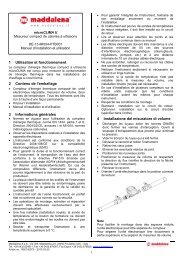
1 Utilisation et fonctionnement<br />
Le compteur d’énergie thermique compact à <strong>jet</strong> <strong>multiple</strong> <strong>coaxial</strong><br />
microCLIMA est conçu pour mesurer la consommation de<br />
l’énergie thermique dans les installations de chauffage à circuit<br />
fermé.<br />
2 Contenu de l’emballage<br />
• Compteur d’énergie thermique composé de: unité électronique,<br />
mesureur de volume, deux sondes de température.<br />
• Kit pour l’installation<br />
• Etiquette de conformité à la norme EN 14154 (2005)<br />
• Kit pour le montage mural (pour version séparable<br />
• seulement): support et étiquette avec ruban adhésif double<br />
face)<br />
• <strong>Manuel</strong> d’installation et d’utilisation<br />
3 Informations générales<br />
• Lire et observer avec attention les points et les spécifications contenus<br />
dans ce manuel<br />
• Normes en vigueur pour l’utilisation du compteur d’énergie<br />
thermique: norme EN 1434, partie 1 et 6; Directive 2004/22/CE,<br />
annexes I et MI-004; normes métrologiques nationales.<br />
• Respecter les dispositions relatives à l’installation des appareils<br />
électriques.<br />
• Pour garantir la durée et le fonctionnement correct de l’instrument,<br />
la composition de l’eau doit être conforme à la directive FW-510<br />
émanée par l’association allemande AGFW (Arbeitsgemeinschaft<br />
für Wärme und Heizkraftwirtschaft).<br />
• Ne pas ôter ou endommager les plombages de l’ instrument. En<br />
cas d’endommagement ou d’enlèvement la garantie et la validité<br />
du contrôle primitif ne sont plus valables.<br />
• L’ instrument sort de l’usine fonctionnant; en parfait état et conforme<br />
aux normes sur la sécurité.<br />
• Pour garantir l’intégrité de l’instrument, l’extraire de son emballage<br />
seulement au moment de l’installation.<br />
• Le opérations de montage, entretien et réparations doivent être<br />
effectuées exclusivement par du personnel spécialisé.<br />
• Nettoyer l’instrument seulement si nécessaire en utilisant un linge<br />
humide.<br />
• Stocker et transporter l’instrument à une température supérieure à<br />
5 °C.<br />
• Si l’instrument est pourvu de sondes de température de retour<br />
intégrées, il doit être installé sur le circuit de retour.<br />
• Une fois installée (installation noyée), la sonde de température et<br />
le boulon de fermeture ne doivent pas être endommagés et les<br />
scellés ne doivent pas être ôtés.<br />
• En cas d’instrument avec sondes de température intégrées dans<br />
le mesureur de volume, respecter la valeur minimum du débit<br />
indiqué sur l’étiquette de l’instrument: q ≥ 24 l/h / q ≥ 50 l/h.<br />
• Attention: pour la sonde de température, l’installation directe est<br />
nécessaire sur le circuit d’entrée.<br />
• En cas d’installation de plusieurs compteurs sur la même unité<br />
s’assurer que les conditions d’installation soient les mêmes pour<br />
chaque instrument.<br />
• Les câbles doivent être maintenus à une distance minimum de<br />
50 cm de sources d’interférence électromagnétique (interrupteurs,<br />
régulateurs, pompes, etc.) et à une distance minimum de 10 cm<br />
d’autres câbles électriques (câbles des senseurs, M-bus, etc.).<br />
• Ne pas entortiller, rallonger ou raccourcir les câbles des sondes<br />
de température.<br />
• Respecter les conditions de montage. Le standard prévoit<br />
l’installation sur le circuit de retour; une version pour l’installation<br />
sur le circuit d’entrée est disponible sur demande.<br />
4 Installation en dispositif de connection (EAS)<br />
Le compteur est pourvu d’une connexion de 2” comme<br />
Indiqué dans la norme14154 (2005) ; il ne nécessite pas<br />
d’adaptateur pour l’installation dans les versions suivantes de<br />
dispositifs de connexion (EAS) ou autres dispositifs compatibles<br />
métrologiquement: les versions ci-dessous n’influencent pas les<br />
prestations métrologiques de l’instrument :<br />
Description<br />
DN<br />
correspondant<br />
Attention:<br />
Pour faciliter le montage dans des espaces<br />
réduits ou peu aisés, l’unité électronique<br />
peut être séparée du compteur<br />
(seulement pour la version amovible).<br />
Pour séparer l’unité électronique appuyer<br />
sur les cotés comme indiqué sur le dessin<br />
et soulever la partie supérieure.<br />
Longueur totale<br />
(mm)<br />
fi letage interne R p<br />
1/2 15 94<br />
fi letage interne R P<br />
3/4 20 100<br />
EAS avec vanne à bille R P<br />
3/4<br />
EAS avec vanne à bille<br />
R P<br />
1<br />
20 147<br />
25 159<br />
UNI R P<br />
3/4 20 105<br />
UNI R P<br />
1 25 105<br />
fi letage externe G 3/4 15 80<br />
15 110<br />
fi letage externe G 1 20 105<br />
20 130<br />
20 190<br />
5 Montage du compteur<br />
Important:<br />
Avant d’effectuer le montage vérifier les points suivants:<br />
1. le dispositif de connexion doit être certifié selon les<br />
indications du tableau page 2(EAS)<br />
2. le dispositif doit reporter l’indication de conformité à<br />
la norme EN14154 (2005).<br />
Si le dispositif est certifié mais l’indication de certifi cation n’est<br />
pas indiquée, il faut appliquer l’étiquette incluse dans la boite<br />
(voir pag.1 contenu de l’emballage). S’il n’est pas certifié il doit<br />
être remplacé.<br />
<strong>Maddalena</strong> S.p.A., Via G.B. <strong>Maddalena</strong>, 2/4, 33040 Povoletto (UD) - Italy<br />
Phone: +39 0432 634811, Fax.: +39 0432.679007, Fax Export.: +39 0432.679820 , www.maddalena.it<br />
Article-No. 1080100016 - 2012-07-25 - MSH<br />
Pagina/Page 15
Pour installer l’instrument, procéder comme suit<br />
– Fermer les robinets<br />
– Vider le morceau de tube qui a été fermé.<br />
– En cas de substitution du compteur, démonter les sondes de<br />
températures<br />
– Oter le bouchon ou le compteur à remplacer du dispositif de<br />
connexion<br />
– Oter le joint, vérifi er la superfi cie et la nettoyer si nécessaire<br />
– Positionner le nouveau joint sur le dispositif de connexion en<br />
maintenant la superficie plane vers le haut.<br />
– Utiliser du gras de silicone pour lubrifier le fi letage du compteur<br />
– Vérifi er le positionnement correct<br />
de l’O-Ring<br />
– Visser le compteur à la main au<br />
début puis visser jusqu’à l’arrêt<br />
complet en utilisant une clé<br />
– Tourner l’intégrateur pour une<br />
position correcte de lecture<br />
8 Unité électronique<br />
L’unité électronique est pourvue d’un display à cristaux liquides à<br />
8 caractères plus quelques symboles spéciaux.<br />
Les données sont organisées sur trois niveaux et peuvent être<br />
visualisées en appuyant sur le bouton qui se trouve sous le display.<br />
La visualisation standard propose la consommation totale d’énergie<br />
depuis la date de mise en marche de l’instrument.<br />
En appuyant brièvement sur le bouton, les données de chaque<br />
niveau défilent.<br />
Le niveau principal sort automatiquement en premier. En appuyant<br />
sur le bouton pendant plus de 4 secondes, on accède aux différents<br />
niveaux. Pour visualiser le niveau souhaité, lâcher le bouton.<br />
Après une minute de non utilisation la visualisation standard<br />
recomparaît.<br />
1. Niveau principal<br />
6 Montage des sondes de température<br />
Pour les canalisations ayant un diamètre inférieur à DN25, la norme<br />
prévoit en cas de nouvelles d’installation ou de remplacement<br />
d’installations obsolètes, le montage des senseurs de température<br />
dans des vannes porte sonde.<br />
• la sonde de température avec l’étiquette rouge doit être<br />
installée sur le circuit d’entrée<br />
• la sonde de température avec l’étiquette bleue doit être installée<br />
sur le circuit de retour.<br />
Installation avec robinet à sphère et raccords TEE<br />
• Oter les bouchons/la sonde à remplacer et le<br />
joint/l’ancien OR. Nettoyer les superfi cies pour<br />
éliminer les éventuels résidus:<br />
• Positionner l’OR dans le filetage du robinet<br />
à sphère/du raccord TEE.<br />
• Insérer la sonde dans le robinet à sphère/dans le<br />
raccord à TEE en s’assurant qu’elle ne touche pas<br />
le fond.<br />
• Régler la profondeur d’immersion de la sonde en<br />
utilisant la vis.<br />
• Serrer avec le boulon.<br />
7 Mise en marche<br />
• Rouvrir lentement les vannes.<br />
• Vérifier l’étanchéité et le fonctionnement.<br />
Après avoir vérifié le fonctionnement correct du système, appliquer<br />
les scellés aux sondes de température et à l’unité électronique.<br />
En cas de substitution du compteur, prendre note de la lecture et du<br />
numéro de série.<br />
Vérifier que:<br />
• Le système de chauffage soit en marche<br />
• Les robinets d’arrêt soient ouverts<br />
• Les conduites ne soient pas bouchées et le fi ltre soit propre<br />
• Les scellés soit appliqués sur les sondes de températures<br />
• La flèche sur le compteur indique la direction correcte<br />
• L’instrument visualise le volume instantané<br />
• Une différence de température vraisemblable soit visualisée<br />
• La sonde de température avec l’étiquette rouge soit installée<br />
dans le circuit d’entrée.<br />
• La sonde de température avec l’étiquette bleue soit installée<br />
dans le circuit de retour.<br />
• Dans les instruments avec sondes de température de retour<br />
intégrées, le compteur doit être installé sur le circuit de retour.<br />
1.) Consommation<br />
totale en MWh<br />
(visualisation<br />
standard)<br />
4.) Volume total en<br />
m 3<br />
4.) Température en<br />
sortie en o C<br />
2.) Test de fonctionnement<br />
du display. Tous<br />
les segments doivent<br />
être visualisés en<br />
même temps.<br />
5.) Puissance instantanée<br />
en kW<br />
3.)Lecture à une date<br />
préfixée. La valeur<br />
s’alterne avec la date<br />
même<br />
6.) Débit instantané<br />
en m 3 /h courante on binaire et hexadécimale<br />
7.) Date 8.) Code d’erreur (visualisati-<br />
alternée)<br />
Seulement sur l’instrument avec deux entrées impulsions:<br />
9.) Registre tarif 1: valeur<br />
alternée au registre et aux<br />
paramètres.<br />
11.) Lecture instantanée du<br />
comptage impulsions 1, alternée<br />
à la valeur impulsions.<br />
2. Niveau technique<br />
1.) Puissance<br />
maximum en kW<br />
7.) Valeur impulsion/<br />
litre<br />
10.)Version firmware/<br />
software<br />
2.) Débit maximum<br />
en m 3 /h<br />
5.) Différence de<br />
température<br />
10.) Registre tarif 2: valeur<br />
alternée au registre et aux<br />
paramètres.<br />
12.)Lecture instantanée du<br />
comptage impulsions 2, alternée<br />
à la valeur impulsions.<br />
3.) Température en<br />
entrée en o C<br />
6.) Jours de fonctionnement<br />
depuis la<br />
date d’étalonnage<br />
8.) Adresse M-bus 9.) Numéro de série<br />
<strong>Maddalena</strong> S.p.A., Via G.B. <strong>Maddalena</strong>, 2/4, 33040 Povoletto (UD) - Italy<br />
Phone: +39 0432 634811, Fax.: +39 0432.679007, Fax Export.: +39 0432.679820 , www.maddalena.it<br />
Article-No. 1080100016 - 2012-07-25 - MSH<br />
Pagina/Page 16
3. Niveau statique<br />
1.) Date de la lecture précédente<br />
alternée avec la valeur correspondante.<br />
Si programmé, on<br />
peut visualiser le volume total,<br />
les valeurs tarifaires ou les valeurs<br />
de chaque instrument relié<br />
aux entrées impulsions<br />
(en option) 1)<br />
2. - 16.) (16) lectures mensuelles:<br />
date alternée à la valeur correspondante.<br />
Si programmé, on<br />
peut visualiser le volume total, les<br />
valeurs tarifaires ou les valeurs<br />
de chaque compteur à<br />
impulsion. 1)<br />
1)<br />
Jusqu’à la fin du mois, la valeur de consommation et la date sont visualisées à 0.<br />
2)<br />
Peut être programmé avec le logiciel approprié. Il nécessite d’un mot de passe<br />
qui doit être demandé au fournisseur.<br />
9 Interfaces et options<br />
9.1 Interface optique (à infrarouges)<br />
Pour le transfert des données du compteur d’énergie thermique à<br />
l’ordinateur, une tête optique est nécessaire ; elle sera connectée<br />
à l’ordinateur. La tête optique et le logiciel nécessaires sont fournis<br />
sur demande.<br />
L’interface optique (à infrarouges) s’active en appuyant sur le bouton<br />
prévu. Si, après 60 secondes, on ne reçoit pas un “télégramme”<br />
valide ou si l’on n’appuie pas de nouveau sur le bouton, l’interface<br />
se désactive.<br />
L’interface optique est alimentée par pile.<br />
9.2 M-bus<br />
9.2.1 Version avec alimentation par M-BUS<br />
Dans cette version, l’interface M-Bus fournit l’alimentation à l’unité<br />
électronique (version sans séparation galvanique) rendant illimité le<br />
nombre de lectures pour chaque instrument.<br />
L’instrument est conforme aux indications du PTB sur l’immunité aux<br />
interférences, garantissant ainsi la sécurité des données retransmises.<br />
9.2.2 Version sans alimentation par M-Bus (avec séparation<br />
galvanique)<br />
Cette version n’est pas alimentée par l’interface M-Bus, donc le<br />
numéro de demandes qui peuvent être envoyées est limité.<br />
Dans un réseau M-bus avec un maximum de 250 instruments, 24<br />
interrogations par jour peuvent être effectuées pour chaque instrument.<br />
Si un nombre inférieur a été effectué et/ou si les instruments<br />
connectés sont en nombre inférieur, le nombre d’interrogations<br />
inutilisées sera stocké.<br />
9.2.3 Observations générales sur l’M-Bus<br />
• L’interface optique est alimenté par la pile ; le nombre de<br />
lecture journalier est donc limité.<br />
• Durant la communication par M-Bus, les autres interfaces<br />
(interface optique) de l’instrument ne sont pas utilisables.<br />
• Le protocole M-Bus est conforme à la norme En 13757-2,<br />
EN13757-3, EN 1434-3 et aux recommandations sur l’M-Bus<br />
(version 4.8 de novembre 1997) – protocole IEC 870 parties<br />
1,2 et 4.<br />
• Les unités électroniques ne supportent pas une tension supérieure<br />
à celle consentie par la tension bus (±50V). Utiliser un level<br />
converter comme mesure de protection supplémentaire.<br />
• L’installation d’un réseau M-Bus doit être effectuée<br />
exclusivement par un personnel qualifi é.<br />
• S’assurer que la structure du réseau M-Bus (longueur et diamètre<br />
des câbles) soit compatible avec la vitesse de transmission<br />
(2400 Baud) de l’instrument connecté.<br />
Câble conseillé : câble téléphonique J-Y (ST) Y2 x 2 0,8 mm 2<br />
9.3 Sorties impulsions (contact à potentiel libre)<br />
La sortie impulsions à potentiel libre est disponible sur demande.<br />
Il s’agit d’un interrupteur électronique (classe OA, standard<br />
EN 1434) à travers lequel les impulsions sont émises. La sortie<br />
impulsions se ferme, en correspondance à la valeur d’impulsions<br />
(la valeur est indiquée sur l’instrument), pendant une durée<br />
de 125 ms. Si durant un mesurage plusieurs impulsions sont<br />
émises, l’intervalle entre deux impulsions sera toujours de 125<br />
ms. L’utilisateur peut utiliser librement le signal en respectant les<br />
valeurs maximum de charge prévue.<br />
Différents instruments peuvent être connectés aux sorties<br />
impulsions.<br />
Valeur impulsions:<br />
Calories: 1kWh/imp. ou autres valeurs sur demande<br />
Volume: 100 l/imp.<br />
Sorties impulsions:<br />
Courant maximum de commutation 300 mA ~/-<br />
Tension maximum de commutation 35 V ~/-<br />
Puissance maximum de commutation 300 mW<br />
Résistance d’isolation<br />
> 10 09 Ohm<br />
Résistance de contact<br />
max. 25 Ohm<br />
Capacité.00<br />
1.5 pF<br />
Courant maximum<br />
120 mA<br />
Rigidité diélectrique (contact ouvert) 350 V ~/-<br />
Durée d’impulsions<br />
Intervalle minimum entre deux<br />
impulsions<br />
9.4 Programmation du data logger<br />
125 ms<br />
125 ms<br />
La fonction data logger est fournie sur demande.<br />
Le data logger mémorise la consommation et les lectures à<br />
intervalles de temps choisis par l’usager.<br />
Les données peuvent être sauvegardées sous différents formats<br />
pour être ensuite utilisées pour l’analyse et la gestion des<br />
consommations.<br />
La lecture des données peut être effectuée via interface optique ou<br />
via M-Bus.<br />
Le data logger fonctionne comme mémoire circulaire, ce qui<br />
signifie que les valeurs courantes sont toujours disponibles et,<br />
quand il n’y a plus de place sur la mémoire, on écrit sur la<br />
donnée la moins récente.<br />
La capacité de la mémoire est d’environ 10.589 chaînes de données.<br />
Le logiciel effectue la lecture d’un compteur à la fois qui peut être<br />
interrogé à travers l’adresse primaire ou secondaire. S’il y a un seul<br />
compteur dans le réseau on peut utiliser l’adresse 254.<br />
Les valeurs suivantes peuvent être programmées en utilisant le<br />
logiciel (une, plusieurs ou toutes):<br />
• Heure (toujours mémorisée)<br />
• Calorie<br />
• Frigorie<br />
• Volume<br />
• Puissance<br />
• Débit<br />
• Température d’entrée<br />
• Température de retour<br />
• Différence de température<br />
<strong>Maddalena</strong> S.p.A., Via G.B. <strong>Maddalena</strong>, 2/4, 33040 Povoletto (UD) - Italy<br />
Phone: +39 0432 634811, Fax.: +39 0432.679007, Fax Export.: +39 0432.679820 , www.maddalena.it<br />
Article-No. 1080100016 - 2012-07-25 - MSH<br />
Pagina/Page 17
L’intervalle de temps de la lecture peut être programmé au choix:<br />
• 1 minute<br />
• 10 minutes<br />
• 15 minutes<br />
• 30 minutes<br />
• 60 minutes<br />
• 3 heures<br />
• 6 heures<br />
• 12 heures<br />
• 24 heures<br />
Selon la programmation, le data logger mémorise entre 2117 et<br />
10589 chaînes des données.<br />
Important<br />
Si les paramètres sont reprogrammés, les données mémorisées<br />
seront perdues!<br />
9.5 Mini-bus<br />
L’interface Mini-Bus est une interface protectrice (n’est pas influencée<br />
par des signaux externes) et est fournie sur demande. Il s’agit<br />
d’une connexion de deux conducteurs à une interface inductive<br />
externe avec extension maximum de 50 m. La communication est<br />
de type “point à point” selon la norme EN 1434-3.<br />
Baudrate: 2400 Baud (également pour l’interface optique).<br />
9.6.1 Programmation de la fonction radio<br />
L‘instrument est livré avec la fonction radio désactivée (v. chap.<br />
9.6.2 Activation de l’interface radio).<br />
Paramètre<br />
Modalité<br />
Options<br />
programmation<br />
S1 / T1: unidirectionnel<br />
S2 / T2: bidirectionnel<br />
Transmission 0:00 - 24:00 7 - 19:00<br />
Intervalle de<br />
transmission<br />
Jours de la<br />
semaine<br />
Semaine de<br />
calendrier<br />
120 secondes - 240<br />
minutes;<br />
programmation spéciale:<br />
mensuelle<br />
Lundi – dimanche<br />
1 - 4 1 - 4<br />
Mois 1 - 12 1 - 12<br />
Programmation<br />
standard<br />
T1 (unidirectionnel)<br />
120 secondes<br />
Lundi - vendredi<br />
Date d‘allumage 01. 01. - 31.12. Non programmé<br />
Cryptographie<br />
AES<br />
Type<br />
télégramme<br />
Activé/non activé;<br />
Même clé pour client ou<br />
commande/clé casuelle<br />
pour compteur<br />
Télégramme bref/<br />
télégramme long<br />
(valeurs mensuelles)<br />
Activé; clé casuelle<br />
pour compteur<br />
Télégramme long<br />
(valeurs<br />
mensuelles)<br />
9.6.2 Activation de l’interface radio<br />
L’instrument sort de l’usine avec la fonction radio désactivée.<br />
L’activation peut être effectuée de deux manières différentes:<br />
9.6 Transmission via radio<br />
Les compteurs d’énergie thermique microCLIMA peuvent être pourvu,<br />
sur demande, d’une interface radio conforme à la Norme européenne<br />
EN 13757-4 relative à la communication wireless M-Bus.<br />
Fréquence de fonctionnement: 868 MHz<br />
Puissance de transmission: jusqu’à 25 mW<br />
Protocole: wireless M-Bus selon la Norme EN 13757-4; modalité de<br />
fonctionnement: T1, S1, T2, S2 au choix.<br />
Télégramme bref pour systèmes fixes de lecture<br />
Télégramme long pour lecture avec système walk by.<br />
L’instrument est programmé en usine avec l’heure solaire (GMT+2).<br />
Veuillez prendre note que:<br />
Heure d’allumage de référence: 7:00<br />
Heure d’extinction de référence: 19:00<br />
Fonctionnement avec heure solaire en cours:<br />
Heure d‘allumage: 7:00<br />
Heure d‘extinction: 19:00<br />
Fonctionnement avec heure légale en cours:<br />
Heure d‘allumage: 8:00<br />
Heure d‘extinction: 20:00<br />
a) Sans utiliser le software: Sélectionner au niveau 2 –<br />
technique “M-bus adresse” (voir chap. 8 unité électronique)<br />
et appuyer sur le bouton pendant plus de trois secondes.<br />
Les programmations d’usine seront alors visibles:<br />
b) En utilisant le logiciel Device Monitor (disponible<br />
sur demande).<br />
La procédure d‘activation de la fonction radio en utilisant le<br />
logiciel est décrite dans le manuel d‘instruction.<br />
9.6.3 Comment vérifier que la fonction radio est<br />
bien activée<br />
Si la fonction radio est activé correctement, un triangle dans l’angle<br />
en bas à gauche du display apparaitra.<br />
Note:<br />
Les compteurs d’énergie radio ne doivent pas être installés derrière<br />
ou entre les tuyauteries de chauffage car le signal pourrait être<br />
perturbé. La présence d’autres instruments pourvus d’interface radio<br />
tels que router WLAN, télécommandes, etc. pourrait créer des interférences.<br />
La structure même de l’édifice dans lequel l’instrument est<br />
installé pourrait influencer le fonctionnement.<br />
<strong>Maddalena</strong> S.p.A., Via G.B. <strong>Maddalena</strong>, 2/4, 33040 Povoletto (UD) - Italy<br />
Phone: +39 0432 634811, Fax.: +39 0432.679007, Fax Export.: +39 0432.679820 , www.maddalena.it<br />
Article-No. 1080100016 - 2012-07-25 - MSH<br />
Pagina/Page 18
9.7 Programmation des deux entrées impulsions<br />
supplémentaires (seulement avec M-Bus ou<br />
interface radio)<br />
Les entrées impulsions 1 + 2 permettent d’effectuer la lecture via<br />
M-bus d’instruments pourvus d’une sortie impulsions.<br />
Les paramètres (valeur impulsions, unité de mesure) peuvent être<br />
enregistrés avec le logiciel approprié. Les valeurs programmables<br />
dépendent de la valeur des impulsions en entrée et de l’unité de<br />
mesure.<br />
• Entrées impulsions conformes à la norme EN 1434-2:2007,<br />
classe IB<br />
• Durée de l’impulsion: ≥ 100 ms<br />
• Fréquence de l’impulsion: ≤ 5 Hz<br />
• Absorption courant: ≤ 1,1 mA<br />
Valeurs programmables:<br />
Valeur impulsion<br />
Unité de mesure<br />
1 Litres/kWh par impulsion<br />
2,5 Litres/kWh par impulsion<br />
10 Litres/kWh par impulsion<br />
25 Litres/kWh par impulsion<br />
100 Litres/kWh par impulsion<br />
250 Litres/kWh par impulsion<br />
1000 Litres/kWh par impulsion<br />
Installation des entrées impulsions<br />
Dans les émetteurs d’impulsions avec collecteur ouvert il faut<br />
respecter la polarité. Durant l’installation les conducteurs ne<br />
doivent pas entrer en contact l’un avec l’autre pour éviter que<br />
l’instrument enregistre les impulsions.<br />
Durant l’installation du compteur mettre au zéro, si nécessaire,<br />
la lecture des instruments connectés et la valeur d’impulsions en<br />
utilisant le logiciel.<br />
9.7.1 Branchement pour câble à 6 fils conducteurs<br />
(longueur du câble: 1 m)<br />
Conducteur<br />
Couleur<br />
1 blanc IE1 +<br />
2 marron IE1 ┴<br />
3 vert IE2 ┴<br />
4 jaune IE2 +<br />
5 gris M-Bus<br />
6 rose M-Bus<br />
IE = entrées impulsions<br />
1 2 3 4 5 6<br />
9.7.2 Branchement pour câble à 4 fils conducteurs<br />
(longueur du câble: 1 m) –<br />
seulement avec wireless M-Bus (radio)<br />
Conducteur<br />
Couleur<br />
1 jaune IE1+<br />
2 vert IE1┴<br />
3 marron IE2┴<br />
4 blanc IE2+<br />
1 2 3 4<br />
9.7.3 Impostation du registre tarif (disponible seulement pour la version avec deux entrées impulsions)<br />
Deux registres tarif sont disponibles pour la totalisation, en fonction des paramètres programmés, de l’énergie ou du temps. Les registres<br />
peuvent etre programmés en utilisant le software approprié et peuvent être visualisés sur display ou téléchargés sur PC.<br />
Exemple de visualisation Exemple de description Registre tarif 1<br />
(pour le mesurage de l’énergie ou du temps)<br />
0 Non défini (programmation de fabrique)<br />
1 Energie (0,683 MWh) mesurée de 18.00 à 6.00 (programmable<br />
avec intervalles de 10 minutes)<br />
2 Energie (0,683 MWh) mesurée dans la période où la puissance<br />
échangée a été ≥ 2.000 kW<br />
3 Energie (0,683 MWh) mesurée dans la période où la puissance<br />
échangée a été ≤ 2.000 kW<br />
4 Energie (0,683 MWh) mesurée dans la période où le débit a<br />
été ≥ 0,600 m 3 /h<br />
5 Energie (0,683 MWh) mesurée dans la période où le débit a<br />
été ≤ 0,600 m 3 /h<br />
6 Durée (11 h) avec température en entrée<br />
≥ 65 o C (intervalles de 0,01 °C)<br />
7 Durée (11 h) avec température en entrée<br />
≤ 65 o C (intervalles de 0,01 °C)<br />
8 Durée (11 h) avec température de retour<br />
≥ 36 o C (intervalles de 0,01 °C)<br />
9 Durée (11 h) avec température de retour<br />
≤ 36 o C (intervalles de 0,01 °C)<br />
10 Energie (0,683 MWh) mesurée avec différence de température<br />
≥ 10 o C (intervalles de 0,01 K)<br />
11 Durée (11 h) durant laquelle la différence de température a<br />
été ≤ 10 o C (intervalles de 0,01 K)<br />
<strong>Maddalena</strong> S.p.A., Via G.B. <strong>Maddalena</strong>, 2/4, 33040 Povoletto (UD) - Italy<br />
Phone: +39 0432 634811, Fax.: +39 0432.679007, Fax Export.: +39 0432.679820 , www.maddalena.it<br />
Article-No. 1080100016 - 2012-07-25 - MSH<br />
Pagina/Page 19
10 Données techniques<br />
Certifications<br />
Attestation d’examen CE du type<br />
DE-07-MI004-PTB001<br />
11 Code d’erreur<br />
Quand l’instrument repère une erreur, ce symbole est<br />
visualisé.<br />
Classe de précision 1) EN 1434-1:2007, class 2 / 3<br />
Débit minimum 1) q i<br />
/q p<br />
horizontal/<br />
vertical<br />
Débit maximum q s<br />
/q p<br />
2:1<br />
Classe électromagnétique<br />
Classe mécanique<br />
Classe de protection<br />
Classe dérangement hydraulique<br />
Unité électronique<br />
1:100/1:50/1:25<br />
M1<br />
E1<br />
IP54<br />
Température de stockage °C +5 °C ... +55 °C<br />
Plage de mesurage<br />
température<br />
U0<br />
°C +1°C... +150 °C<br />
Différence de température K 3 K... 100 K<br />
Alimentation<br />
Standard<br />
Option<br />
Pile lithium 3V<br />
Pile lithium 3 V + M-Bus<br />
Large battery<br />
Durée de la pile Standard 6 ans +1<br />
Mémorisation données Journalière / E 2 PROM<br />
Display<br />
Interface<br />
Mesureur de volume à <strong>jet</strong> unique<br />
LCD à 8 chiffres + caractères spéciaux<br />
Standard Optique à infrarouges<br />
M-Bus, M-Bus-VS, sortie<br />
impulsion, Mini-Bus, 2 entrées<br />
Option<br />
impulsions supplémentaires<br />
(version M-Bus-VS)<br />
Débit nominal q p<br />
m³/h 0.6 1.5 2.5<br />
Débit maximum q s<br />
1)<br />
m³/h 1.2 3.0 5.0<br />
Perte de charge ∆p à q p<br />
mbar 120 225 240<br />
MAP bar 25<br />
PN bar 16<br />
Démarrage<br />
Horizontale<br />
2.5 3.5 4<br />
l/h<br />
Vertical 3 5 6<br />
Filetage externe 2“<br />
Plage de mesurage température °C 15 °C... 90 °C<br />
Installation<br />
Sondes de température<br />
Modèle PT500<br />
Connexion<br />
Diamètre<br />
horizontale; vertical<br />
Résistance de précision en platine<br />
2 fils conducteurs<br />
5 mm (en option 5,2 mm ou 6 mm)<br />
Longueur du câble 1.5 m (en option 3.0 m)<br />
1)<br />
La classe de précision et le débit minimum sont indiqués sur<br />
l’instrument.<br />
L’erreur peut être visualisée à la position 8 du niveau principal<br />
même en forme binaire.<br />
L’instrument relève sept typologies d’erreur différentes qui peuvent<br />
se vérifier conjointement.<br />
Code binaire<br />
Description de l’erreur<br />
Code<br />
exadécimal<br />
1 dans la position 1 Erreur Check sum error 40<br />
1 dans la position 2 Erreur E2PROM error 20<br />
1 dans la position 3 Reset error 10<br />
1 dans la position 4 Erreur bobine error 08<br />
1 dans la position 5 Erreur sonde de référence error 04<br />
1 dans la position 6 Erreur sonde de<br />
température retour ou<br />
sonde non connectée<br />
1 dans la position 7 Erreur sonde de<br />
température entrée ou<br />
sonde non connectée<br />
Exemple: erreur bobine<br />
Erreur<br />
code<br />
Erreur<br />
Code<br />
binaire LCD<br />
Erreur Check sum<br />
Erreur E 2 PROM<br />
Reset<br />
Erreur bobine<br />
Erreur sonde de référence<br />
Erreur sonde de température retour<br />
ou sonde non connectée<br />
fErreur sonde de température<br />
entrée ou sonde non connectée<br />
1 2 3 4 5 6 7<br />
error 02<br />
error 01<br />
Code<br />
exadécimal<br />
( LCD)<br />
En cas d’erreur , sauf pour le Reset, on conseille de<br />
substituer l’instrument et de le renvoyer au fournisseur pour les<br />
contrôles nécessaires.<br />
12 Déclaration de conformité<br />
Nous déclarons que le produit décrit dans ce manuel est conforme<br />
aux directives suivantes :<br />
• Directive 2004/22/CE du Parlement Européen et du Conseil du<br />
31 mars 2004 relative aux instruments de mesure, annexes I et<br />
MI-004.<br />
• Directive 2004/108/CE du Parlement Européen et du Conseil du<br />
15 décembre 2004 relative à la compatibilité électromagnétique.<br />
• Directive 2006/95/CE du Parlement Européen et du Conseil du<br />
12 décembre 2006 relative à la basse tension.<br />
La déclaration de conformité est disponible sur le site<br />
www.engelmann.de.<br />
<strong>Maddalena</strong> S.p.A., Via G.B. <strong>Maddalena</strong>, 2/4, 33040 Povoletto (UD) - Italy<br />
Phone: +39 0432 634811, Fax.: +39 0432.679007, Fax Export.: +39 0432.679820 , www.maddalena.it<br />
Article-No. 1080100016 - 2012-07-25 - MSH<br />
Pagina/Page 20
Les instructions de montage suivantes sont<br />
seulement valables pour la version séparable!<br />
13 Montage avec support mural<br />
L’unité électronique peut être séparée du mesureur de volume<br />
et peut être fi xée sur le mur en utilisant le support prévu. Si<br />
possible, monter le support au dessus du mesureur de volume.<br />
B. Montage à vis*<br />
Appuyer légèrement sur les cotés comme indiqué sur le dessin et<br />
ôter la partie supérieure en la soulevant.<br />
L’unité électronique doit être installée de telle sorte que le<br />
display soit toujours lisible et accessible<br />
Kit de montage mural (seulement pour la version séparable):<br />
1 support mural<br />
1 étiquette bi-adhésive<br />
Percer des trous sur le mur (diamètre 6 mm, profondeur 40 mm).<br />
Vérifi er la longueur maximum du câble blanc de connexion<br />
entre le mesureur de volume et l’unité électronique.<br />
Fixer le support au mur.<br />
A. Montage avec étiquette biadhésive<br />
Appuyer légèrement sur les cotés comme indiqué sur le dessin et<br />
ôter la partie supérieure en la soulevant.<br />
Monter l’unité électronique sur le support.<br />
*vis et chevilles ne sont pas comprises dans la confection<br />
Fixer le support sur l’instrument.<br />
Oter un des deux feuillets de protection sur l’étiquette bi adhésive.<br />
Coller l’étiquette bi adhésive sur le support mural.<br />
Retirer l’autre feuillet de protection et positionner l’instrument à<br />
l’endroit désiré en exerçant une légère pression.<br />
C. Enlévement de l’unité électronique du mur<br />
Pousser vers le haut et enlever.<br />
14 Contacts<br />
<strong>Maddalena</strong> S.p.A.<br />
Via G.B. <strong>Maddalena</strong>, 2/4,<br />
33040 Povoletto (UD)<br />
Italy<br />
Phone: +39 0432 634811<br />
Fax: +39 0432 679007<br />
Fax Export: +39 0432 679820<br />
www.maddalena.it<br />
Sauf modifi cations techniques.<br />
Les piles usées, les appareils que ne sont plus utilisés et les<br />
composants doivent être déposés dans les centres de récolte<br />
prévus à cet effet.<br />
<strong>Maddalena</strong> S.p.A., Via G.B. <strong>Maddalena</strong>, 2/4, 33040 Povoletto (UD) - Italy<br />
Phone: +39 0432 634811, Fax.: +39 0432.679007, Fax Export.: +39 0432.679820 , www.maddalena.it<br />
Article-No. 1080100016 - 2012-07-25 - MSH<br />
Pagina/Page 21