evoluzione degli acciai da cemento armato nuovi prodotti ... - Sismic
evoluzione degli acciai da cemento armato nuovi prodotti ... - Sismic
evoluzione degli acciai da cemento armato nuovi prodotti ... - Sismic

You also want an ePaper? Increase the reach of your titles
YUMPU automatically turns print PDFs into web optimized ePapers that Google loves.
EVOLUZIONE DEGLI ACCIAI DA CEMENTO ARMATO<br />
NUOVI PRODOTTI PER LE RETI<br />
ED I TRALICCI ELETTROSALDATI<br />
di<br />
Alberto Franchi -<br />
Politecnico di Milano e Università di Brescia<br />
Chairman WG 2 - TC19/SC 1<br />
Paolo Riva -<br />
Paola Ronca -<br />
Università di Brescia<br />
Politecnico di Milano
Ringraziamenti:<br />
Questo lavoro é stato possibile grazie alla collaborazione continua tra il Laboratorio Prove<br />
Materiali “P. Pisa” dell’Universitá di Brescia e la società ALFA Acciai spa di Brescia.<br />
Un particolare ringraziamento ai tecnici del Laboratorio: G. Duina, S. Curcio, A. Del Barba,<br />
L. Martinelli, ed al responsabile Ing. Enrico Donini per la loro collaborazione altamente<br />
professionale.<br />
Un riconoscimento va attribuito agli studenti A. Bontempi ed S. Mingotti che hanno condotto<br />
alcune delle prove come parte integrante della loro tesi di laurea.<br />
Infine, si vuole riconoscere il contributo di idee, esperienze, e discussioni che il “gruppo<br />
<strong>acciai</strong>” del Servizio Tecnico Centrale del Ministero dei Lavori Pubblici ha sempre riservato<br />
agli autori della presente memoria.
Evoluzione <strong>degli</strong> <strong>acciai</strong> <strong>da</strong> <strong>cemento</strong> <strong>armato</strong>... pagina 1<br />
INDICE<br />
1. INTRODUZIONE..............................................................................................................................................2<br />
2. LA NORMATIVA EUROPEA SUGLI ACCIAI DA CEMENTO ARMATO ENV 10080 [2] ..................3<br />
2.1 CENNI STORICI....................................................................................................................................................3<br />
2.2 PROSPETTIVE FUTURE .........................................................................................................................................4<br />
3. ALCUNI ACCENNI ALLE NORME EXTRA EUROPEE CON PARTICOLARE RIFERIMENTO<br />
ALLE ZONE SISMICHE: STATI UNITI, AUSTRALIA, GIAPPONE ED ISRAELE .................................5<br />
3.1 ACI DETAILING MANUAL - 1994 [3]...................................................................................................................5<br />
3.2 AUSTRALIAN STANDARD (AS 3600-1988) [4] ....................................................................................................6<br />
3.3 LA NORMATIVA ISRAELIANA [5] .........................................................................................................................6<br />
3.4 GLI ACCIAI GIAPPONESI [6, 7]..............................................................................................................................6<br />
4. LA NORMATIVA NAZIONALE [1]...............................................................................................................7<br />
5. ALCUNE PROVE SULLA NUOVA RETE AD ALTA DUTTILITÁ..........................................................7<br />
6. CONCLUSIONI.................................................................................................................................................9<br />
7. BIBLIOGRAFIA................................................................................................................................................9
Evoluzione <strong>degli</strong> <strong>acciai</strong> <strong>da</strong> <strong>cemento</strong> <strong>armato</strong>... pagina 2<br />
1. INTRODUZIONE<br />
Gli <strong>acciai</strong> <strong>da</strong> <strong>cemento</strong> <strong>armato</strong> rappresentano un prodotto del settore delle costruzioni<br />
importante per l’Italia nel contesto europeo (Fig. 1), che ha conosciuto mutamenti profondi<br />
negli ultimi anni sia nei processi produttivi sia nella struttura industriale nazionale.<br />
Il settore normativo cogente italiano, il Consiglio Superiore dei Lavori Pubblici ed il Servizio<br />
Tecnico Centrale dello stesso, l’Ente normativo tecnico volontario, 12 a SC Unsider, e l’Ente<br />
normatore europeo ECISS/TC19/SC1 stanno seguendo tale <strong>evoluzione</strong> cercando di indicare le<br />
direzioni di sviluppo alle imprese, cercando di assicurare alle stesse un ambito di regole<br />
chiare e durature sulla base di un indirizzo tecnico che vede la sicurezza delle costruzioni al<br />
primo posto tra i requisiti che tale prodotto deve assicurare.<br />
L’Universitá di Brescia si trova nella felice situazione di essere vicina come territorio ai<br />
produttori e contemporaneamente coinvolta, tramite alcuni suoi docenti, nel lavoro che sia il<br />
Consiglio Superiore dei Lavori Pubblici, sia la SC 12 dell’ Unsider, sia l’ECISS/TC19/SC1<br />
conducono per normare tale prodotto.<br />
Questa memoria ha lo scopo di presentare alcuni problemi normativi aperti, soprattutto con<br />
riferimento all’ <strong>acciai</strong>o per costruzioni in c.a. in zone sismiche, e le tendenze sia a livello<br />
nazionale che a livello europeo.<br />
In particolare il prodotto “rete elettrosal<strong>da</strong>ta” ottenuta <strong>da</strong> <strong>acciai</strong>o trafilato a freddo ha avuto<br />
nel passato e continua ad avere tuttora, una regolamentazione dibattuta e controversa tra<br />
l’Ente normatore cogente, produttori e mondo accademico.<br />
La società ALFA <strong>acciai</strong>, spinta <strong>da</strong> tale controversa normativa, ha pensato di proporre al<br />
normatore prima, ed ora al mercato, un prodotto completamente nuovo: una rete <strong>da</strong> rotolo<br />
laminato a caldo.<br />
I risultati sperimentali del Laboratorio dell’Universitá di Brescia sono stati alla base per<br />
l’accreditamento di tale prodotto <strong>da</strong> parte del Servizio Tecnico Centrale del Ministero dei<br />
Lavori Pubblici e vengono presentati e commentati nel paragrafo finale di questa memoria.
Evoluzione <strong>degli</strong> <strong>acciai</strong> <strong>da</strong> <strong>cemento</strong> <strong>armato</strong>... pagina 3<br />
2. LA NORMATIVA EUROPEA SUGLI ACCIAI DA CEMENTO ARMATO ENV<br />
10080 [2]<br />
2.1 Cenni Storici<br />
La norma ENV 10080 [2] e’ stata preparata <strong>da</strong>ll’ SC1 “Acciaio <strong>da</strong> <strong>cemento</strong> <strong>armato</strong> non<br />
precompresso” del Technical Committee ECISS/TC19 “Acciaio <strong>da</strong> <strong>cemento</strong> <strong>armato</strong>: qualità,<br />
dimensioni e tolleranze” il cui segretariato viene tenuto <strong>da</strong>ll’ Ente normatore tedesco DIN.<br />
Il lavoro dell’ ECISS/TC 19/ SC 1 é cominciato nel 1988 con lo scopo di pervenire ad una<br />
norma EN con specifiche unificate in tema di proprietà meccaniche e dimensioni di barre,<br />
rotolo e rete elettrosal<strong>da</strong>ta per <strong>cemento</strong> <strong>armato</strong> in grado di soddisfare le richieste della<br />
progettazione delle strutture in <strong>cemento</strong> <strong>armato</strong>.<br />
Si sono svolte 9 riunioni plenarie dell’ ECISS/TC19/SC1 con la partecipazione di 17 stati<br />
membri e rappresentanti delle organizzazioni con cui sono stati stabiliti rapporti di mutuo<br />
scambio come: (i) il sotto comitato CEN/TC250/SC2 - Structural Eurocodes; Eurocode 2:<br />
Design of Concrete structures; (ii) il sotto comitato ISO/TC17/SC16 - Steels for the<br />
reinforcement and prestressing of concrete; (iii) la European Fabric Reinforcement<br />
Association (E.F.R.A.) che annovera stati non facenti parte della Comunità Europea.<br />
Dopo 5 anni di riunioni e discussioni, anche se si era raggiunto un accordo su alcuni punti<br />
fon<strong>da</strong>mentali quali i livelli di resistenza, la sal<strong>da</strong>bilitá, il range dei diametri etc, non é stato<br />
possibile raggiungere un accordo completo tra la maggioranza qualificata dei paesi membri<br />
che permettesse la pubblicazione di una genuina norma EN.<br />
Nella riunione del maggio 1993 si é presa la decisione, confermata <strong>da</strong>ll’inchiesta scritta nel<br />
successivo mese di Novembre, di conferire al documento su cui si é coagulato l’accordo lo<br />
status di Norma Provvisoria ENV contenente le condizioni di produzione e distribuzione<br />
dell’<strong>acciai</strong>o B500 A e B500B.<br />
La ragione principale che ha condotto ad una tale scelta é stata individuata nella decisione di<br />
pubblicare l’ Eurocodice 2 come ENV (ENV 1992-1-1: Design of concrete structures - Part<br />
1.1: General rules and rules for building) aperto a completamenti e modifiche in un numero<br />
ragionevole di anni. La vita prevista per la ENV 10080 dovrebbe essere armonizzata con<br />
quella della ENV 1992-1-1.<br />
Punti principali, sui quali l’accordo non é stato ampio e qualificato, e che devono pertanto<br />
essere ridiscussi risultano:<br />
1. la ricerca di un accordo con gli Eurocodici 2, 4 e 8 sulla stan<strong>da</strong>rdizzazione di 2 o più di<br />
2 categorie di <strong>acciai</strong>o in base a diversi livelli di duttilità; l’ ECISS/TC19/SC1 é<br />
favorevole a normare un <strong>acciai</strong>o con valori di duttilità più elevati se ciò viene
Evoluzione <strong>degli</strong> <strong>acciai</strong> <strong>da</strong> <strong>cemento</strong> <strong>armato</strong>... pagina 4<br />
richiesto <strong>da</strong>ll’ Eurocodice 8 (costruzioni in zona sismica) o per altre particolari<br />
applicazioni (centrali nucleari, strutture marine etc.);<br />
2. il chiarimento sulla misura di deformazione a carico massimo A gt in sostituzione delle<br />
misure dopo rottura a cavallo della zona di rottura A 5 o A 10 ;<br />
3. la eventuale definizione di valori minimi, in aggiunta ai valori caratteristici, per le<br />
quantità che misurano la duttilità A gt e R m /R e ;<br />
4. la formulazione di una prova di fatica per la rete;<br />
5. le specifiche di una tale prova;<br />
6. il possibile aumento al 6% delle tolleranze sulla massa per i diametri piccoli (fino a<br />
10mm.);<br />
7. l’eventuale estensione delle procedure di qualificazione e verifica della conformità<br />
<strong>degli</strong> <strong>acciai</strong> con le specifiche della norma.<br />
Nella Tabella 1 vengono riportate le caratteristiche meccaniche e geometriche richieste <strong>da</strong>lla<br />
ENV 10080 per barre, rotolo e rete elettrosal<strong>da</strong>ta.<br />
Nella tabella 2 le caratteristiche chimiche per assicurare la sal<strong>da</strong>bilitá.<br />
2.2 Prospettive future<br />
Nella riunione del 24 maggio 1995 in Düsseldorf del TC10/SC1 si é presa la decisione di<br />
costituire formalmente un “working group” WG2 composto <strong>da</strong> un esponente designato <strong>da</strong><br />
ogni stato membro più uno-due esperti dell’Eurocodice 8.<br />
I lavori di tale WG sono coordinati <strong>da</strong> A. Franchi e ad UNSIDER é affi<strong>da</strong>ta la segreteria.<br />
La prima riunione si é tenuta a Düsseldorf il 6 dicembre 1995 e la secon<strong>da</strong> riunione a Milano<br />
il 24 aprile 1996.<br />
Il lavoro tecnico del WG2 dovrà confluire per le decisioni finali nell’attività del TC19/SC1.<br />
Al fine di contribuire in maniera scientifica al lavoro del WG2, l’UNSIDER ha coordinato un<br />
gruppo di 8 tra i produttori leader italiani allo scopo di finanziare una ricerca con<br />
L’Universitá di Brescia per chiarire i limiti sperimentali dell’<strong>acciai</strong>o 500 nelle applicazioni in<br />
zona sismica e pervenire contemporaneamente alla definizione delle caratteristiche di un<br />
nuovo <strong>acciai</strong>o, se ciò si rendesse necessario.<br />
Un primo documento sui risultati di tale ricerca, ottenuti entro la fine del 95, é già disponibile<br />
ed é stato presentato al Convegno UNSIDER-UNIV. BS sugli <strong>acciai</strong> <strong>da</strong> c.a. tenuto a Brescia il<br />
9 Febbraio 1996.<br />
La responsabilità di un tale lavoro é accresciuta <strong>da</strong>ll’importanza del settore <strong>acciai</strong>o <strong>da</strong><br />
<strong>cemento</strong> <strong>armato</strong> italiano in ambito europeo illustrata in Fig. 1 in cui viene riportata<br />
l’<strong>evoluzione</strong> della produzione dei principali paesi europei negli ultimi cinque anni.<br />
Per poter capire le direzioni future occorre tenere ben presente alcuni punti:
Evoluzione <strong>degli</strong> <strong>acciai</strong> <strong>da</strong> <strong>cemento</strong> <strong>armato</strong>... pagina 5<br />
(i) la sicurezza delle costruzioni in <strong>cemento</strong> <strong>armato</strong> si traduce nella richiesta di duttilità<br />
minima <strong>degli</strong> <strong>acciai</strong> che oggi si può stimare mediante i seguenti parametri in corso di<br />
verifica sperimentale (A gt ) ≥ 7-8% ; (Rm/Re) ≥ 1.12 - 1.13 contro valori della ENV<br />
10080 di A gt ≥ 5 % e (R m /R e ) ≥ 1.08; la sicurezza viene esaltata come requisito<br />
essenziale nelle costruzioni in zona sismica ma rimane tale anche in territori meno<br />
sfortunati;<br />
(ii) i produttori tendono naturalmente al prodotto unico; storicamente la norma ha posto<br />
sempre dei vincoli solo inferiori alla resistenza. I produttori sono stati sempre così<br />
bravi <strong>da</strong> a<strong>da</strong>ttarsi con la tecnologia in modo <strong>da</strong> sviluppare un solo prodotto in grado<br />
<strong>da</strong> rispettare le prescrizioni di tutte le categorie previste <strong>da</strong>lla normativa;<br />
(iii) la progettazione delle strutture in c.a. si é resa consapevole del pericolo di imporre<br />
solo dei limiti inferiori alla resistenza. La sezione in c.a. può essere costituita <strong>da</strong> un<br />
<strong>acciai</strong>o più “prestazionale” di quello previsto <strong>da</strong>l progettista e <strong>da</strong>re adito ad una<br />
rottura fragile anche se ad un livello di carico superiore al massimo previsto.<br />
(iv) negli anni passati le normative hanno teso a richiedere agli <strong>acciai</strong> resistenze sempre<br />
più elevate, soprattutto i paesi importatori di un tale prodotto; oggi tale tendenza si sta<br />
invertendo, ritenendo il fattore sicurezza più importante rispetto al costo aggiuntivo<br />
che un <strong>acciai</strong>o meno resistente comporta sull’intero settore delle costruzioni;<br />
(v) una unica classe di resistenza, con classi diverse di duttilità per prodotto tipo barra,<br />
rotolo, rete, e traliccio, come oggi previsto <strong>da</strong>lla 10080, sembra un elemento di<br />
semplificazione del mercato di notevole importanza e che rimane esigenza primaria<br />
anche nella revisione in corso della norma stessa.<br />
3. ALCUNI ACCENNI ALLE NORME EXTRA EUROPEE CON PARTICOLARE<br />
RIFERIMENTO ALLE ZONE SISMICHE: STATI UNITI, AUSTRALIA,<br />
GIAPPONE ED ISRAELE<br />
3.1 ACI Detailing Manual - 1994 [3]<br />
3.1.1 - Le armature atte a resistere alle azioni assiali e flettenti negli elementi di telaio ed<br />
elementi di parete devono soddisfare i requisiti richiesti <strong>da</strong>lle norme ASTM per l’ <strong>acciai</strong>o<br />
A706M. Gli <strong>acciai</strong> tipo A615M nei gradi 300 e 400 sono ammessi se:<br />
(a) (R e ) act ≤ (R e ) nom + 120 MPa<br />
(tests aggiuntivi non devono superare tale valore di ulteriori 20 MPa) e<br />
(b) (R m ) act / (R e ) act ≥ 1.25<br />
2.1.2 - Sal<strong>da</strong>ture. Sono ammesse sal<strong>da</strong>ture delle barre longitudinali. Non sono ammesse<br />
sal<strong>da</strong>ture tra barre longitudinali e barre trasversali a meno che sia assicurato un continuo<br />
controllo competente delle operazioni di sal<strong>da</strong>tura come nel caso del prodotto rete.
Evoluzione <strong>degli</strong> <strong>acciai</strong> <strong>da</strong> <strong>cemento</strong> <strong>armato</strong>... pagina 6<br />
Nelle Tabelle 3 e 4 vengono riportate le caratteristiche meccaniche richieste <strong>da</strong>lle norme<br />
ASTM per gli <strong>acciai</strong> tipo A615 M e A706 M.<br />
Osservazioni:<br />
a) numero di diametri molto limitato e presenza di diametri grandi (max 8 diametri);<br />
b) la norma prevede per l’ <strong>acciai</strong>o A706M un limite inferiore allo snervamento (400<br />
MPa) ed un limite superiore (540 MPa) con un range di valori piuttosto ampio (140<br />
MPa);<br />
c) il rapporto (R m /R e ) min ≥ 1.25 piuttosto elevato;<br />
d) la misura di duttilità viene eseguita su una lunghezza base fissa (200 mm) e la richiesta<br />
minima varia con il diametro della barra.<br />
3.2 Australian Stan<strong>da</strong>rd (AS 3600-1988) [4]<br />
Le resistenze <strong>degli</strong> <strong>acciai</strong> Australiani vengono riportate in Tabella 5.<br />
Il riferimento normativo sono le AS 1302 per le barre, le AS 1303 per il rotolo e le AS 1304<br />
per le reti.<br />
Per le costruzioni in zona sismica si richiede che l’<strong>acciai</strong>o sia sal<strong>da</strong>bile con contenuto di<br />
carbonio massimo di 0.22 % per le barre e 0.25% per il rotolo, con un valore di carbonio<br />
equivalente inferiore a 0.39%. Tale valore risulta sensibilmente inferiore a quanto richiesto<br />
<strong>da</strong>lla norma europea (0.52% sul prodotto).<br />
3.3 La normativa Israeliana [5]<br />
In Tabella 6 vengono riportati i valori delle caratteristiche meccaniche richieste.<br />
Si osserva la similitudine con l’A706M americano con un valore superiore dello snervamento<br />
più piccolo (520 MPa).<br />
Caratteristica della norma Israeliana, la prova a basso numero di cicli. In Tabella 7 vengono<br />
forniti i valori numerici di riferimento. Si tratta di effettuare tre cicli a deformazione media<br />
imposta alla frequenza compresa tra 1 e 3 Hz. La barra non deve presentare fratture o cricche<br />
dopo l’effettuazione della prova.<br />
3.4 Gli <strong>acciai</strong> giapponesi [6, 7]<br />
In Tabella 8 vengono riportate le caratteristiche meccaniche <strong>degli</strong> <strong>acciai</strong> <strong>da</strong> <strong>cemento</strong> <strong>armato</strong><br />
Giapponesi.<br />
In zona sismica l’<strong>acciai</strong>o SD50 (tipo 500) non é ammesso (sono previsti il 300,350 e 400).
Evoluzione <strong>degli</strong> <strong>acciai</strong> <strong>da</strong> <strong>cemento</strong> <strong>armato</strong>... pagina 7<br />
Non si possono usare diametri superiori a 38 mm. (D38).<br />
Valori limite superiore della tensione di snervamento variano tra 1.25 e 1.30 R e .<br />
Si può usare <strong>acciai</strong>o ad alta resistenza per armatura a taglio (1300 MPa, barre per<br />
precompresso).<br />
4. LA NORMATIVA NAZIONALE [1]<br />
Il D.M. del 9 Gennaio 1996 disciplina le proprietà meccaniche delle barre <strong>da</strong> c.a. mediante il<br />
prospetto 2-I per le categorie FeB 38K e FeB 44K, il filo di <strong>acciai</strong>o trafilato o laminato a<br />
freddo per reti e tralicci mediante il prospetto 3-I, le reti e i tralicci mediante il prospetto 4-I e<br />
la composizione chimica per la sal<strong>da</strong>bilitá dell’<strong>acciai</strong>o mediante la tabella del punto 2.2.6.<br />
Tali prescrizioni vengono riportate nelle Tabelle 9-10-11, rispettivamente.<br />
Due osservazioni sembrano importanti:<br />
1. nel paragrafo 2.2.3.1 “Caratteristiche meccaniche e tecnologiche” riguar<strong>da</strong>nti le barre<br />
ad aderenza migliorata, il normatore ha introdotto per la prima volta, ed in maniera<br />
sfumata, per le costruzioni in zona sismica il concetto di limite superiore allo<br />
snervamento (f y /f yk ) e di un limite inferiore all’incrudimento medio (f t /f y ) m , dove f y é<br />
la tensione di snervamento della singola prova, e f yk é il valore caratteristico della<br />
tensione di snervamento. Tale indicazione e’ in linea con quanto richiesto, come già<br />
accennato, <strong>da</strong>lle ACI americane ed altri;<br />
2 viene confermato per la rete il rapporto f tk /f yk ≥ 1.10, prova <strong>da</strong> effettuarsi senza<br />
trattamento termico, dove f tk e f yk sono, rispettivamente, il valore di rottura e di<br />
snervamento [f y (0,2 %)] caratteristico (valore che ha il 95% di probabilità che il 95%<br />
delle prove forniscano valori superiori).<br />
5. ALCUNE PROVE SULLA NUOVA RETE AD ALTA DUTTILITÁ<br />
Qui di seguito vengono riportati i primi risultati di una serie di prove che il laboratorio Prove<br />
Materiali “P. Pisa” dell’Università di Brescia sta eseguendo su incarico della società ALFA<br />
Acciai spa di Brescia, al fine di caratterizzare le proprietà meccaniche del nuovo prodotto di<br />
rete.<br />
Una prima serie di prove viene riassunta nelle Tabelle 12.1 e 12.2, con riferimento alla rete<br />
con filo φ 6÷12 sia nella tipologia denominata A.D. (alta duttilità), che nella tipologia H<br />
(High). Tali <strong>da</strong>ti sono desunti <strong>da</strong>i certificati ufficiali del Laboratorio dell’Università di<br />
Brescia relativi alla verifica della qualità del mese di aprile 1996.
Evoluzione <strong>degli</strong> <strong>acciai</strong> <strong>da</strong> <strong>cemento</strong> <strong>armato</strong>... pagina 8<br />
Il primo prodotto presenta, dopo trattamento termico, una tensione caratteristica di<br />
snervamento pari a 488 MPa con un valore caratteristico del rapporto R m /R e di 1.20 ed una<br />
A 10 media intorno al 15.5%. Valori molto interessanti che fanno presumere un ottimo<br />
comportamento nella formazione delle cerniere plastiche delle strutture in c.a.<br />
La tensione di snervamento non supera i 500 MPa. Pertanto, oggi tale prodotto non supera i<br />
requisiti imposti <strong>da</strong>lla ENV 10080 e perciò il suo utilizzo può essere previsto solo sul<br />
territorio nazionale.<br />
Per tale motivo la società ALFA ha pensato ad una rete di tipo H. In tal caso la tensione<br />
caratteristica di snervamento è pari a 519 MPa ma il valore caratteristico del rapporto R m /R e e<br />
l’A 10 medio scendono a 1.16 e circa 13%, rispettivamente. Valori pertanto conformi sia alla<br />
normativa ENV 10080 che alla norma Italiana vigente.<br />
Il primo prodotto, tuttavia, pone prospettive di utilizzo più ampie che in qualche misura si<br />
possono sovrapporre all’utilizzo delle barre, mentre il secondo sembra limitato ad elementi<br />
bidimensionali.<br />
Una secon<strong>da</strong> serie di prove é stata mirata al confronto tra vecchio e nuovo prodotto della<br />
società ALFA, paragonando una serie di reti ottenuta <strong>da</strong>l vecchio trafilato a freddo con<br />
tensione di snervamento superiore a 500 MPa e le nuove reti ottenute con rotolo laminato a<br />
caldo (tipo A.D.).<br />
Le prove hanno preso in considerazione i diametri 5,6,8,10,12 e sono state eseguite prove per<br />
spostamento imposto fino a rottura, prove cicliche a basso numero di cicli (fatica plastica),<br />
prove cicliche ad alto numero di cicli (fatica elastica).<br />
Nelle Tabelle 13-15 e nelle Figure 2-6 vengono riportati i risultati delle prove monoassiali<br />
per i diametri φ = 5,6,8,10,12 mm, sovrapponendo in ciascun diagramma le curve relative al<br />
prodotto trafilato ed a quello laminato.<br />
Si osserva una tensione di snervamento più bassa del prodotto laminato (materiale meno<br />
incrudito) rispetto a quello trafilato che, a parità di tensione di rottura, fornisce un maggiore<br />
rapporto R m /R e . La duttilità in termini di Agt risulta sempre molto superiore, dell’ordine di<br />
2÷3 volte per il prodotto laminato rispetto a quello trafilato.<br />
Le prove di fatica oligociclica sono state effettuate imponendo uno spostamento ciclico tale<br />
<strong>da</strong> produrre una deformazione media assiale pari a ±3%. La lunghezza libera del provino é<br />
stata assunta pari a 80 mm.<br />
Nelle Figure 7-9 vengono forniti i diagrammi forza-tempo sovrapponendo i diagrammi del<br />
prodotto trafilato con quello laminato per i diametri φ = 8,10,12 mm. Risulta abbastanza<br />
evidente la tendenza alla diminuzione della resistenza più rapi<strong>da</strong> nel prodotto trafilato rispetto<br />
a quello laminato. Alcune prove hanno fornito un comportamento analogo tra i due <strong>prodotti</strong><br />
ed una tale indicazione suggerisce un supplemento di in<strong>da</strong>gine e di interpretazione meccanica.
Evoluzione <strong>degli</strong> <strong>acciai</strong> <strong>da</strong> <strong>cemento</strong> <strong>armato</strong>... pagina 9<br />
6. CONCLUSIONI<br />
L’<strong>acciai</strong>o <strong>da</strong> <strong>cemento</strong> <strong>armato</strong> ha visto negli ultimi anni uno sviluppo tecnologico, industriale e<br />
normativo tale <strong>da</strong> richiedere studi, prove, ricerche e dibattiti al fine di chiarire meglio sia le<br />
direttive normative nazionali ed europee, sia la caratterizzazione meccanica e metallurgica di<br />
tale prodotto.<br />
Il ripensamento di norme e <strong>prodotti</strong> per costruzioni in zona sismica é stato uno dei motivi<br />
principali che hanno messo in dubbio lo sviluppo passato e pongono nuove mete e direzioni<br />
per lo sviluppo futuro.<br />
La definizione di una nuova classe di <strong>acciai</strong> 500 ad alta duttilità all’interno della norma ENV<br />
10080, ad esempio il B500C per barre, rotolo e rete, oppure l’accordo su un livello di<br />
resistenza più basso, ad esempio 450 MPa, se i livelli di duttilità richiesti al 500 non fossero<br />
ottenibili su base industriale con una certa facilità, sembrano le due possibilità che oggi si<br />
fronteggiano a livello europeo e che troveranno una soluzione nel prossimo futuro.<br />
Il prodotto rete <strong>da</strong> laminato della ditta Alfa Acciai spa, qualificati ai fini del D.M. 14.2.92, ed<br />
in prospettiva del nuovo D.M. 9.1.96, <strong>da</strong>l Laboratorio Prove Materiali “P. Pisa”<br />
dell’Università di Brescia, presenta caratteristiche di duttilità altamente innovative rispetto<br />
alla tradizionale rete <strong>da</strong> trafilato, tali <strong>da</strong> farne prevedere l’utilizzo privilegiato per quelle<br />
applicazioni strutturali in cui la formazione e lo sviluppo della “cerniera plastica” nella<br />
struttura in <strong>cemento</strong> <strong>armato</strong> risulta una caratteristica irrinunciabile al fine di soddisfare i<br />
livelli di sicurezza richiesti. Per quanto sopra, le strutture in zona ad alto rischio sismico<br />
sembrano la naturale destinazione di tale prodotto.<br />
7. BIBLIOGRAFIA<br />
1. D.M. 9 gennaio 1996, Norme tecniche per il calcolo, l’esecuzione ed il collaudo delle<br />
strutture in <strong>cemento</strong> <strong>armato</strong>, normale e precompresso e per le strutture metalliche.<br />
2. ENV 10080, Steel for the reinforcement of concerete. Wel<strong>da</strong>ble ribbed reinforcing steel<br />
B500. Technical delivery conditions for bars, coils and welded fabric, April 1995.<br />
3. ACI Detailing Manual 1994, Publication SP 66 (94), American Concrete Institute,<br />
Detroit.<br />
4. Australian Stan<strong>da</strong>rd, Concrete Structures, AS 3600-1988.<br />
5. Israelian Stan<strong>da</strong>rd, Steel for the reinforcement of concrete: ribbed bars, SI 739, November<br />
1993.<br />
6. Japanese Industrial Stan<strong>da</strong>rd, Steel bars for concrete reinforcement, JIS G 3112-1975.<br />
7. DIJ, Structural Design Guidelines for Reinforced Concrete Buildings (1994).
Evoluzione <strong>degli</strong> <strong>acciai</strong> <strong>da</strong> <strong>cemento</strong> <strong>armato</strong>... pagina 10<br />
APPENDICE I<br />
TABELLE
Evoluzione <strong>degli</strong> <strong>acciai</strong> <strong>da</strong> <strong>cemento</strong> <strong>armato</strong>... pagina 11<br />
APPENDICE II<br />
FIGURE
Evoluzione <strong>degli</strong> <strong>acciai</strong> <strong>da</strong> <strong>cemento</strong> <strong>armato</strong>... pagina 12<br />
Tabella 12.1 - Prove su rete tipo A.D. (<strong>da</strong> prove di verifica della qualità del mese di aprile<br />
1996 effettuate <strong>da</strong>l Laboratorio dell’Università di Brescia).<br />
Tabella 12.2 - Prove su rete tipo H (<strong>da</strong> prove di verifica della qualità del mese di aprile 1996<br />
effettuate <strong>da</strong>l Laboratorio dell’Università di Brescia).
LIST OF TABLES<br />
Table 1 – Characteristics of tested specimens.<br />
Table 2 – Failure <strong>da</strong>ta for first series of specimens.<br />
Table 3 – Failure <strong>da</strong>ta for second series of specimens.
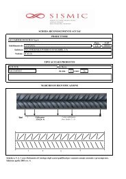
Table 1<br />
Specimen Rebars Mesh type Axial L. L. Hist. Section<br />
B16R8-1 12φ16+10φ8 none none Fig. 3a a<br />
B16R8-2 12φ16+10φ8 none none Fig. 3a a<br />
B14HR8-1 12φ14 Cold Drawn φ8 600kN Fig. 3b b<br />
B14CD8-1 12φ14 Hot Rolled φ8 600kN Fig. 3b b<br />
B14HR8-2 12φ14 Cold Drawn φ8 600kN Fig. 3c b<br />
B14CD8-2 12φ14 Hot Rolled φ8 600kN Fig. 3c b<br />
HR12C-1 none Cold Drawn φ12 600kN Fig. 3d c<br />
CD12C-1 none Hot Rolled φ12 600kN Fig. 3d c<br />
HR12C-2 none Cold Drawn φ12 600kN Fig. 3d c<br />
CD12C-2 none Hot Rolled φ12 600kN Fig. 3d c<br />
B14HR8S 12φ14 Cold Drawn φ8 none Fig. 3a f<br />
B14HR8U 12φ14 Hot Rolled φ8 none Fig. 3a g<br />
B14CD8S 12φ14 Cold Drawn φ8 none Fig. 3a f<br />
B14CD8U 12φ14 Hot Rolled φ8 none Fig. 3a g<br />
HR12S none Cold Drawn φ12 none Fig. 3a d<br />
HR12U none Hot Rolled φ12 none Fig. 3a e<br />
CD12S none Cold Drawn φ12 none Fig. 3a d<br />
CD12U none Hot Rolled φ12 none Fig. 3a e
Table 2<br />
V max<br />
Specimen Ductility Drift Ratio<br />
E tot<br />
δ u /δ y δ u /H [kN] [J]<br />
B16R8-1 2.5 1/45 339 35 382.8<br />
B16R8-2 4.0 1/34 340 91 702.0<br />
B14HR8-1 3.0 1/42 330 56 577.3<br />
B14CD8-1 2.5 1/45 340 45 608.4<br />
B14HR8-2 3.0 1/42 330 123 335.9<br />
B14CD8-2 3.0 1/39 357 74 923.9<br />
HR12C-1 3.5 1/37 +290 -525 71 436.1<br />
CD12C-1 2.4 1/51 +370 -580 38 690.8<br />
HR12C-2 3.0 1/43 +305 -555 99 582.2<br />
CD12C-2 3.0 1/43 +340 -575 86 783.3<br />
δ y = estimated yield displacement based on approximate<br />
bi-linearization of response;<br />
δ u = ultimate displ. corresponding to 80% of max. force;<br />
V max = maximum shear;<br />
E tot = total dissipated energy.<br />
N.B.<br />
all specimens with WW mesh showed early<br />
confinement failure
Table 3<br />
V max<br />
Specimen Ductility Drift Ratio<br />
E tot<br />
δ u /δ y δ u /H [kN] [J]<br />
B14HR8S 3.8 1/35 400 83 963.1<br />
B14HR8U 4.6 1/29 405 135 763.2<br />
B14CD8S 2.5 1/47 400 43 186.5<br />
B14CD8U 2.5 1/46 480 82 595.1<br />
HR12S 3.4 1/36 335 68 865.4<br />
HR12U 3.9 1/34 420 71 923.8<br />
CD12S 2.0 1/70 390 12 126.6<br />
CD12U 2.6 1/49 460 36 452.4<br />
δ y = estimated yield displacement based on approximate<br />
bi-linearization of response;<br />
δ u = ultimate displ. corresponding to 80% of max. force;<br />
V max = maximum shear;<br />
E tot = total dissipated energy.
LIST OF FIGURES<br />
Fig. 1 –<br />
Fig. 2 –<br />
Fig. 3 –<br />
Fig. 4 –<br />
Fig. 5 –<br />
Fig. 6 –<br />
Characteristics and reinforcement detailing of tested specimens.<br />
Test set-up and reaction frame.<br />
Loading Histories.<br />
Typical uniaxial stress-strain curves for tested steels.<br />
Typical crack pattern on panels.<br />
P-δ curves for specimens reinforced with ordinary rebars only.<br />
Fig. 7 – a) and b) – base section crack pattern at 3δ 1 for panel B16R8-2; c) buckling of<br />
longitudinal bars; d) low cycle fatigue failure of a longitudinal bar.<br />
Fig. 8 –<br />
P-δ curves for specimens B14HR8 and B14CD8.<br />
Fig. 9 – a) base section crack pattern at 4δ 1 for panel B14HR8-2; b) mesh opening and weld<br />
detachment at collapse for panel B14HR8-2; c) crack pattern at collapse for specimen<br />
B14CD8-2; d) tensile failure of φ8 welded wire mesh for specimen B14CD8-2.<br />
Fig. 10 – P-δ curves for specimens HR12C and CD12C.<br />
Fig. 11 – a) crack pattern before collapse for panel HR12C-1; b) buckling of longitudinal bars for<br />
specimen HR12C-1; c) crack pattern before collapse for specimen CD12C-1; d) tensile<br />
failure of φ12 welded wire mesh for specimen CD12C-1.<br />
Fig. 12 – Dissipated energy vs. Cycle amplitude for first series of tests.<br />
Fig. 13 – P-δ curves for specimens B14HR8S, B14HR8U, B14CD8S, and B14CD8U.<br />
Fig. 14 – a) crack pattern before collapse for panel B14HR8U; b) concrete spalling for panel<br />
B14HR8U; c) crack pattern before collapse for specimen B14CD8S; d) tensile failure of<br />
a φ14 rebar and φ8 welded wire mesh for specimen B14CD8S.<br />
Fig. 15 – P-δ curves for specimens HR12S, HR12U, CD12S, and CD12U.<br />
Fig. 16 – Base crack opening versus horizontal force curves for panels HR12U and CD12U.<br />
Fig. 17 – Dissipated energy vs. Cycle amplitude for second series of tests.<br />
Riva, Franchi
Fig. 1<br />
Riva, Franchi
Components<br />
1. Reaction Frame<br />
2. Screw Jack<br />
3. Supporting Beam<br />
4. Lateral Frame<br />
5. Lateral Guides<br />
6. Vertical Load<br />
Supports<br />
7. Vertical Load Jack<br />
8. R:C. Panel<br />
Fig. 2<br />
5<br />
4<br />
3<br />
2<br />
1<br />
0<br />
-1<br />
-2<br />
-3<br />
-4<br />
-5<br />
δ/δ1<br />
5<br />
4<br />
3<br />
2<br />
1<br />
0<br />
-1<br />
-2<br />
-3<br />
-4<br />
-5<br />
δ/δ1<br />
0 1 2 3 4 5<br />
Cycle<br />
Horizontal Displacement<br />
Axial Force<br />
Fh/Fh,max. cycle<br />
1<br />
0.8<br />
0.6<br />
0.4<br />
0.2<br />
0<br />
-0.2<br />
-0.4<br />
-0.6<br />
-0.8<br />
-1<br />
Horizontal Force<br />
Axial Force<br />
0 1 2 3 4 5<br />
Cycle<br />
a) b)<br />
0 1 2 3 4 5<br />
Cycle<br />
800<br />
600<br />
400<br />
200<br />
0<br />
-200<br />
-400<br />
-600<br />
-800<br />
Axial Force [kN]<br />
5<br />
4<br />
3<br />
2<br />
1<br />
0<br />
-1<br />
-2<br />
-3<br />
-4<br />
-5<br />
δ/δ1<br />
Horizontal Displacement<br />
Axial Force<br />
0 1 2 3 4 5<br />
Cycle<br />
c) d)<br />
Fig. 3<br />
800<br />
600<br />
400<br />
200<br />
0<br />
-200<br />
-400<br />
-600<br />
-800<br />
800<br />
600<br />
400<br />
200<br />
0<br />
-200<br />
-400<br />
-600<br />
-800<br />
Axial Force [kN]<br />
Axial Force [kN]<br />
Riva, Franchi
700<br />
600<br />
σ [MPa]<br />
500<br />
400<br />
300<br />
200<br />
100<br />
0<br />
Hot Rolled d12 Wire Mesh<br />
Cold Drawn d12 Wire Mesh<br />
Tempcore d16 Rebar<br />
0 2 4 6 8 10<br />
ε [%]<br />
12<br />
Fig. 4<br />
Riva, Franchi
Fig. 5<br />
Riva, Franchi
600<br />
400<br />
200<br />
Force [kN]<br />
0<br />
B16R8-1 – f c = 40 MPa<br />
Bars φ16 No Mesh<br />
f y = 540MPa<br />
f t = 635MPa<br />
f t/f y = 1.18<br />
ε u = 11.2%<br />
600.00<br />
400.00<br />
200.00<br />
Force [kN]<br />
0.00<br />
B16R8-2 – f c = 40 MPa<br />
Bars φ16 No Mesh<br />
f y = 540MPa<br />
f t = 635MPa<br />
f t /f y = 1.18<br />
ε u = 11.2%<br />
-200<br />
-200.00<br />
-400<br />
-400.00<br />
-600<br />
-80 -60 -40 -20 0 20 40 60 80<br />
Displacement [mm]<br />
-600.00<br />
-80 -60 -40 -20 0 20 40 60 80<br />
Displacement [mm]<br />
Fig. 6<br />
a) b)<br />
c) d)<br />
Fig. 7<br />
Riva, Franchi
600<br />
400<br />
200<br />
Force [kN]<br />
0<br />
B14HR8 –1 - f c = 40 MPa<br />
Bars φ14 HR Mesh 8mm<br />
f y = 540MPa f y = 435MPa<br />
f t = 635MPa f t = 540MPa<br />
f t/f y = 1.18 f t/f y = 1.24<br />
ε u = 11.2% ε u = 8.5%<br />
600<br />
400<br />
200<br />
Force [kN]<br />
0<br />
B14CD8 –1 - f c = 40 MPa<br />
Bars φ14 CD Mesh 8mm<br />
f y = 540MPa f y = 540MPa<br />
f t = 635MPa f t = 605MPa<br />
f t /f y = 1.18 f t /f y = 1.12<br />
ε u = 11.2% ε u = 4.1%<br />
-200<br />
-200<br />
-400<br />
-400<br />
-600<br />
-80 -60 -40 -20 0 20 40 60 80<br />
Displacement [mm]<br />
-600<br />
-80 -60 -40 -20 0 20 40 60 80<br />
Displacement [mm]<br />
600<br />
400<br />
200<br />
Force [kN]<br />
0<br />
B14HR8 –2 - f c = 40 MPa<br />
Bars φ14 HR Mesh 8mm<br />
f y = 540MPa f y = 435MPa<br />
f t = 635MPa f t = 540MPa<br />
f t/f y = 1.18 f t/f y = 1.24<br />
ε u = 11.2% ε u = 8.5%<br />
600<br />
400<br />
200<br />
Force [kN]<br />
0<br />
B14CD8 –2 - f c = 40 MPa<br />
Bars φ14 CD Mesh 8mm<br />
f y = 540MPa f y = 540MPa<br />
f t = 635MPa f t = 605MPa<br />
f t /f y = 1.18 f t /f y = 1.12<br />
ε u = 11.2% ε u = 4.1%<br />
-200<br />
-200<br />
-400<br />
-400<br />
-600<br />
-80 -60 -40 -20 0 20 40 60 80<br />
Displacement [mm]<br />
-600<br />
-80 -60 -40 -20 0 20 40 60 80<br />
Displacement [mm]<br />
Fig. 8<br />
a) b)<br />
c) d)<br />
Fig. 9<br />
Riva, Franchi
600<br />
400<br />
200<br />
Force [kN]<br />
0<br />
HR12C-1 - f c = 40 MPa<br />
No Bars HR Mesh 12mm<br />
f y = 442MPa<br />
f t = 568MPa<br />
f t /f y = 1.29<br />
ε u = 8.3%<br />
600<br />
400<br />
200<br />
Force [kN]<br />
0<br />
HR12C-2 - f c = 40 MPa<br />
No Bars HR Mesh 12mm<br />
f y = 442MPa<br />
f t = 568MPa<br />
f t /f y = 1.29<br />
ε u = 8.3%<br />
-200<br />
-200<br />
-400<br />
-400<br />
-600<br />
-80 -60 -40 -20 0 20 40 60 80<br />
Displacement [mm]<br />
-600<br />
-80 -60 -40 -20 0 20 40 60 80<br />
Displacement [mm]<br />
600<br />
400<br />
200<br />
Force [kN]<br />
0<br />
CD12C-1 - f c = 40 MPa<br />
No Bars CD Mesh 12mm<br />
f y = 552MPa<br />
f t = 619MPa<br />
f t /f y = 1.12<br />
ε u = 4.0%<br />
600<br />
400<br />
200<br />
Force [kN]<br />
0<br />
CD12C-2 - f c = 40 MPa<br />
No Bars CD Mesh 12mm<br />
f y = 552MPa<br />
f t = 619MPa<br />
f t /f y = 1.12<br />
ε u = 4.0%<br />
-200<br />
-200<br />
-400<br />
-400<br />
-600<br />
-80 -60 -40 -20 0 20 40 60 80<br />
Displacement [mm]<br />
-600<br />
-80 -60 -40 -20 0 20 40 60 80<br />
Displacement [mm]<br />
Fig. 10<br />
Riva, Franchi
a) b)<br />
c) d)<br />
Fig. 11<br />
Riva, Franchi
Dissipated Energy [kJ]<br />
60<br />
50<br />
40<br />
30<br />
20<br />
10<br />
0<br />
First Series of Tests<br />
B16R8-1 B16R8-2<br />
B14HR8-1 B14CD8-1<br />
B14HR8-2 B14CD8-2<br />
HR12C-1 CD12C-1<br />
HR12C-2 CD12C-2<br />
0 20 40 60 80<br />
Cycle Amplitude [±mm]<br />
Fig. 12<br />
Riva, Franchi
600<br />
400<br />
200<br />
Force [kN]<br />
0<br />
B14HR8S - f c = 28 MPa<br />
Bars φ14 HR Mesh 8mm<br />
f y = 540MPa f y = 488MPa<br />
f t = 635MPa f t = 570MPa<br />
f t /f y = 1.18 f t /f y = 1.17<br />
ε u = 11.2% ε u = 10.3%<br />
600<br />
400<br />
200<br />
Force [kN]<br />
0<br />
B14HR8U - f c = 28 MPa<br />
Bars φ14 HR Mesh 8mm<br />
f y = 540MPa f y = 488MPa<br />
f t = 635MPa f t = 570MPa<br />
f t /f y = 1.18 f t /f y = 1.17<br />
ε u = 11.2% ε u = 10.3%<br />
-200<br />
-200<br />
-400<br />
-400<br />
-600<br />
-80 -60 -40 -20 0 20 40 60 80<br />
Displacement [mm]<br />
-600<br />
-80 -60 -40 -20 0 20 40 60 80<br />
Displacement [mm]<br />
600<br />
400<br />
200<br />
Force [kN]<br />
0<br />
B14CD8S – f c = 28 MPa<br />
Bars φ14 CD Mesh 8mm<br />
f y = 540MPa f y = 622MPa<br />
f t = 635MPa f t = 642MPa<br />
f t /f y = 1.18 f t /f y = 1.03<br />
ε u = 11.2% ε u = 4.7%<br />
600<br />
400<br />
200<br />
Force [kN]<br />
0<br />
B14CD8U - f c = 28 MPa<br />
Bars φ14 CD Mesh 8mm<br />
f y = 540MPa f y = 622MPa<br />
f t = 635MPa f t = 642MPa<br />
f t /f y = 1.18 f t /f y = 1.03<br />
ε u = 11.2% ε u = 4.7%<br />
-200<br />
-200<br />
-400<br />
-400<br />
-600<br />
-80 -60 -40 -20 0 20 40 60 80<br />
Displacement [mm]<br />
-600<br />
-80 -60 -40 -20 0 20 40 60 80<br />
Displacement [mm]<br />
Fig. 13<br />
a) b)<br />
c) d)<br />
Fig. 14<br />
Riva, Franchi
600<br />
400<br />
200<br />
Force [kN]<br />
0<br />
HR12S - f c = 28 MPa<br />
No Bars HR Mesh 12mm<br />
f y = 522MPa<br />
f t = 603MPa<br />
f t /f y = 1.16<br />
ε u = 10.0%<br />
600<br />
400<br />
200<br />
Force [kN]<br />
0<br />
HR12U - f c = 28 MPa<br />
No Bars HR Mesh 12mm<br />
f y = 522MPa<br />
f t = 603MPa<br />
f t /f y = 1.16<br />
ε u = 10.0%<br />
-200<br />
-200<br />
-400<br />
-400<br />
-600<br />
-80 -60 -40 -20 0 20 40 60 80<br />
Displacement [mm]<br />
-600<br />
-80 -60 -40 -20 0 20 40 60 80<br />
Displacement [mm]<br />
600<br />
400<br />
200<br />
Force [kN]<br />
0<br />
CD12S - f c = 28 MPa<br />
No Bars CD Mesh 12mm<br />
f y = 632MPa<br />
f t = 687MPa<br />
f t /f y = 1.09<br />
ε u = 4.6%<br />
600<br />
400<br />
200<br />
Force [kN]<br />
0<br />
CD12U - f c = 28 MPa<br />
No Bars CD Mesh 12mm<br />
f y = 632MPa<br />
f t = 687MPa<br />
f t /f y = 1.09<br />
ε u = 4.6%<br />
-200<br />
-200<br />
-400<br />
-400<br />
-600<br />
-80 -60 -40 -20 0 20 40 60 80<br />
Displacement [mm]<br />
-600<br />
-80 -60 -40 -20 0 20 40 60 80<br />
Displacement [mm]<br />
Fig. 15<br />
600<br />
600<br />
400<br />
400<br />
200<br />
Force [kN]<br />
0<br />
-200<br />
-400<br />
-600<br />
HR12U - f c = 28 MPa<br />
No Bars HR Mesh 12mm<br />
f y = 522MPa<br />
f t = 603MPa<br />
f t /f y = 1.16<br />
ε u = 10.0%<br />
-5 0 5 10 15<br />
Base Crack Opening [mm]<br />
200<br />
Force [kN]<br />
0<br />
-200<br />
-400<br />
-600<br />
CD12U - f c = 28 MPa<br />
No Bars CD Mesh 12mm<br />
f y = 632MPa<br />
f t = 687MPa<br />
f t /f y = 1.09<br />
ε u = 4.6%<br />
-5 0 5 10 15<br />
Base Crack Opening [mm]<br />
Fig. 16<br />
Riva, Franchi
Dissipated Energy [kJ]<br />
60<br />
50<br />
40<br />
30<br />
20<br />
10<br />
0<br />
Second Series of Tests<br />
B14HR8S B14CD8S<br />
B14HR8U B14CD8U<br />
HR12S<br />
CD12S<br />
HR12U<br />
CD12U<br />
0 20 40 60 80<br />
Cycle Amplitude [±mm]<br />
Fig. 17<br />
Riva, Franchi