• Scatola in alluminio di forma compatta a tenuta stagna. • Camma in ...
• Scatola in alluminio di forma compatta a tenuta stagna. • Camma in ...
• Scatola in alluminio di forma compatta a tenuta stagna. • Camma in ...

You also want an ePaper? Increase the reach of your titles
YUMPU automatically turns print PDFs into web optimized ePapers that Google loves.
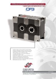
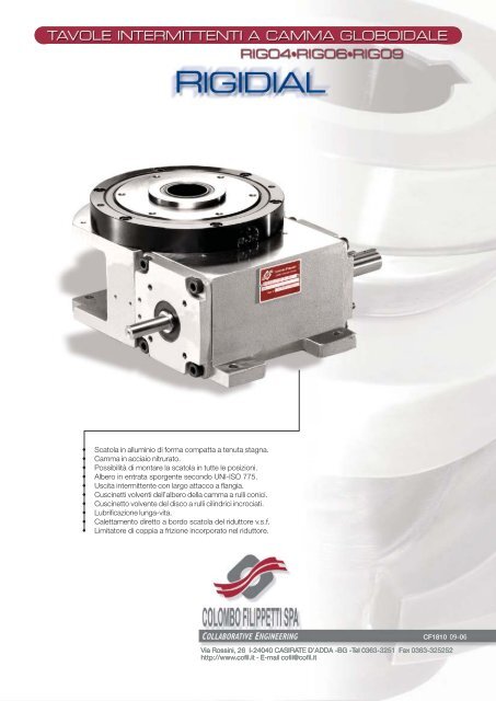
<strong>•</strong> <strong>Scatola</strong> <strong>in</strong> allum<strong>in</strong>io <strong>di</strong> <strong>forma</strong> <strong>compatta</strong> a <strong>tenuta</strong> <strong>stagna</strong>.<br />
<strong>•</strong> <strong>Camma</strong> <strong>in</strong> acciaio nitrurato.<br />
<strong>•</strong> Possibilità <strong>di</strong> montare la scatola <strong>in</strong> tutte le posizioni.<br />
<strong>•</strong> Albero <strong>in</strong> entrata sporgente secondo UNI-ISO 775.<br />
<strong>•</strong> Uscita <strong>in</strong>termittente con largo attacco a flangia.<br />
<strong>•</strong> Cusc<strong>in</strong>etti volventi dell’albero della camma a rulli conici.<br />
<strong>•</strong> Cusc<strong>in</strong>etto volvente del <strong>di</strong>sco a rulli cil<strong>in</strong>drici <strong>in</strong>crociati.<br />
<strong>•</strong> Lubrificazione lunga-vita.<br />
<strong>•</strong> Calettamento <strong>di</strong>retto a bordo scatola del riduttore v.s.f.<br />
<strong>•</strong> Limitatore <strong>di</strong> coppia a frizione <strong>in</strong>corporato nel riduttore.<br />
CF1810 09-06<br />
Via Ross<strong>in</strong>i, 26 I-24040 CASIRATE D’ADDA -BG -Tel 0363-3251 Fax 0363-325252<br />
http://www.cofil.it - E-mail cofil@cofil.it
TAVOLE INTERMITTENTI<br />
A CAMMA GLOBOIDALE<br />
Sommario<br />
PAG<br />
1. Generalità ......................................................................... 2<br />
2. Funzionamento................................................................... 2<br />
3. Zona <strong>di</strong> pericolo.................................................................. 3<br />
4. Esempi <strong>di</strong> applicazioni .......................................................... 3<br />
5. Scelta del tipo.................................................................... 4<br />
6. Istruzioni <strong>di</strong> montaggio ........................................................ 4<br />
7. Impiego del motore autofrenante .......................................... 4<br />
8. Istruzioni per un funzionamento corretto ............................... 4<br />
9. Messa <strong>in</strong> funzione............................................................... 5<br />
10. Manutenzione .................................................................... 5<br />
11. Posizioni <strong>di</strong> montaggio della tavola. ........................................ 5<br />
12. Dimensioni <strong>di</strong> <strong>in</strong>gombro RIGIDIAL 4........................................ 6<br />
13. Versioni opzionali ................................................................ 7<br />
14. Dimensioni <strong>di</strong> <strong>in</strong>gombro RIGIDIAL 6........................................ 8<br />
15. Versioni opzionali ................................................................ 9<br />
16. Dimensioni <strong>di</strong> <strong>in</strong>gombro RIGIDIAL 9...................................... 10<br />
17. Versioni opzionali .............................................................. 11<br />
18. Tabelle delle caratteristiche................................................ 12<br />
19. Riduttori a vite senza f<strong>in</strong>e .................................................. 14<br />
20. Impiego del limitatore <strong>di</strong> coppia ........................................... 14<br />
21. Lubrificazione ................................................................... 15<br />
22. Montaggio e uso della camma per micro<strong>in</strong>terruttore.............. 15<br />
23. Designazione per l’ord<strong>in</strong>e ................................................... 16<br />
Le unità <strong>di</strong> misura sono conformi al sistema metrico <strong>in</strong>ternazionale SI<br />
Le tolleranze generali <strong>di</strong> fabbricazione sono secondo UNI – ISO 2768-1 UNI EN 22768-1<br />
Illustrazioni e <strong>di</strong>segni secondo UNI 3970 (ISO 128-82)<br />
Il metodo <strong>di</strong> rappresentazione dei <strong>di</strong>segni convenzionale<br />
La Colombo Filippetti Spa si riserva il <strong>di</strong>ritto <strong>di</strong> effettuare <strong>in</strong> qualsiasi momento mo<strong>di</strong>fiche utili a migliorare i propri<br />
prodotti. I valori contenuti nel presente catalogo non risultano pertanto v<strong>in</strong>colanti.<br />
Il presente catalogo annulla e sostituisce i precedenti.<br />
Non è ammessa la riproduzione , anche parziale , del contenuto e delle illustrazioni del presente catalogo.<br />
1
TAVOLE INTERMITTENTI<br />
A CAMMA GLOBOIDALE<br />
1. Generalità<br />
RIGIDIAL, la nuova serie <strong>di</strong> tavole rotanti a camme globoidali che tras<strong>forma</strong> il moto rotatorio cont<strong>in</strong>uo <strong>in</strong> moto<br />
<strong>in</strong>termittente, è stata progettata per ottenere le migliori per<strong>forma</strong>nces ad un prezzo molto contenuto.<br />
Il piatto <strong>in</strong>termittente appoggia su un cusc<strong>in</strong>etto <strong>di</strong> largo <strong>di</strong>ametro a rulli <strong>in</strong>crociati, che può sopportare<br />
considerevoli carichi assiali e ribaltanti mantenendo alti livelli <strong>di</strong> precisione e <strong>di</strong> rigi<strong>di</strong>tà.<br />
La camma <strong>di</strong> alta precisione è nitrurata e assicura: resistenza all’usura, scorrevolezza, movimenti dolci,<br />
posizionamenti precisi e assoluta assenza <strong>di</strong> gioco <strong>in</strong> stazione. Un accurato progetto delle camme consente una<br />
vasta gamma <strong>di</strong> movimenti standard, <strong>in</strong>cluso il meccanismo a 2 stazioni (180° <strong>di</strong> rotazione) che è ideale per<br />
applicazioni <strong>di</strong> ribaltamento, o scambio pezzi.<br />
La fusione <strong>in</strong> allum<strong>in</strong>io a <strong>tenuta</strong> <strong>stagna</strong> presenta una buona adattabilità <strong>di</strong> applicazione <strong>in</strong> spazi limitati e la<br />
possibilità <strong>di</strong> montaggio con ogni orientamento. A richiesta la tavola può essere fornita con un foro centrale<br />
passante che consente <strong>di</strong> trasferire a bordo tavola l<strong>in</strong>ee <strong>di</strong> asservimento elettriche e idrauliche.<br />
Le RIGIDIAL fornite con motoriduttore autofrenante vengono dotate, nella versione standard, <strong>di</strong> un limitatore <strong>di</strong><br />
coppia a frizione che serve come sicurezza contro le rotture che possono essere provocate da fermate <strong>di</strong><br />
emergenza nella fase <strong>di</strong> traslazione.<br />
2. Funzionamento<br />
Nelle tavole RIGIDIAL, ad esclusione delle 20-24-32 stazioni, un ciclo completo viene generalmente prodotto <strong>in</strong><br />
un giro completo dell’albero <strong>di</strong> entrata o della camma.<br />
L’angolo <strong>di</strong> rotazione della camma che fa ruotare la tavola cedente da una stazione alla successiva, è<br />
denom<strong>in</strong>ato angolo <strong>di</strong> spostamento ed <strong>in</strong><strong>di</strong>cato col simbolo “B”<br />
Il rimanente angolo <strong>di</strong> rotazione della camma che mantiene bloccato il piatto <strong>in</strong> stazione, viene denom<strong>in</strong>ato<br />
periodo <strong>di</strong> pausa ed <strong>in</strong><strong>di</strong>cato con la sigla “Bp”.<br />
I perio<strong>di</strong> <strong>di</strong> spostamento e <strong>di</strong> pausa della camma determ<strong>in</strong>ano, <strong>in</strong> funzione della velocità <strong>di</strong> rotazione della stessa,<br />
rispettivamente il tempo <strong>di</strong> spostamento ed il tempo <strong>di</strong> pausa del ciclo <strong>in</strong>termittente.<br />
Due sono i mo<strong>di</strong> <strong>di</strong> impiego delle tavole RIGIDIAL:<br />
<strong>•</strong> A consenso elettrico; è impiegato nelle applicazioni <strong>in</strong> cui viene richiesto un tempo <strong>di</strong> pausa elevato rispetto al<br />
tempo <strong>di</strong> traslazione. In questo modo <strong>di</strong> funzionamento il tempo <strong>di</strong> pausa viene determ<strong>in</strong>ato per mezzo <strong>di</strong> una<br />
camma che, posizionata <strong>di</strong>rettamente sull’albero <strong>di</strong> entrata della tavola, azionando un micro<strong>in</strong>terruttore, provoca<br />
la fermata del motore autofrenante o il <strong>di</strong>s<strong>in</strong>nesto <strong>di</strong> un gruppo frizione-freno all’<strong>in</strong>terno del periodo <strong>di</strong> pausa<br />
meccanico della camma. Il segnale <strong>di</strong> partenza della tavola, che produce il passaggio alla stazione successiva e<br />
la conseguente fermata <strong>in</strong> stazione, viene <strong>in</strong>viato solo alla f<strong>in</strong>e <strong>di</strong> tutte le operazioni tecnologiche previste dal ciclo<br />
<strong>di</strong> lavorazione per quella applicazione.<br />
<strong>•</strong> Rotazione <strong>in</strong> cont<strong>in</strong>uo; viene impiegata <strong>in</strong> applicazioni veloci dove il ciclo <strong>di</strong> macch<strong>in</strong>a viene eseguito <strong>in</strong> un giro<br />
dell’albero pr<strong>in</strong>cipale, riservando ad ogni s<strong>in</strong>gola operazione un settore dell’angolo giro. Questo modo <strong>di</strong><br />
funzionamento è riservato a macch<strong>in</strong>e <strong>in</strong> cui i movimenti sono realizzati esclusivamente con sistemi <strong>di</strong><br />
azionamento meccanici.<br />
0<br />
360 ( Gra<strong>di</strong> )<br />
s v a<br />
Fig. 1 Esempio <strong>di</strong> <strong>di</strong>agramma SVA (Spostamenti, Velocità, Accelerazioni.)<br />
2
TAVOLE INTERMITTENTI<br />
A CAMMA GLOBOIDALE<br />
3. Zona <strong>di</strong> pericolo<br />
Trattandosi <strong>di</strong> una apparecchiatura ad azionamento positivo, un <strong>di</strong>sco porta attrezzi con attrezzi posto sulla<br />
tavola si muove unicamente nella sua area. Il movimento può essere arrestato solamente togliendo tensione al<br />
motore <strong>di</strong> azionamento o <strong>in</strong> seguito a rottura <strong>di</strong> elementi della trasmissione; l’uso <strong>di</strong> un limitatore <strong>di</strong> coppia serve<br />
unicamente a proteggere il meccanismo, non le persone. E’ necessario qu<strong>in</strong><strong>di</strong>, durante il funzionamento, non<br />
superare la zona <strong>di</strong> pericolo.<br />
In caso <strong>di</strong> <strong>in</strong>terventi <strong>di</strong> manutenzione è obbligatorio escludere l’alimentazione del motore prima <strong>di</strong> superare la<br />
zona pericolosa.<br />
4. Esempi <strong>di</strong> applicazioni<br />
L’applicazione <strong>di</strong> questa tavola è ugualmente valida nei sistemi a moto <strong>in</strong>termittente sia l<strong>in</strong>eari che rotativi <strong>di</strong><br />
piccole e me<strong>di</strong>e <strong>di</strong>mensioni, dove sono <strong>di</strong>sponibili spazi molto limitati e dove le <strong>in</strong>termittenze molto rapide devono<br />
essere esenti da colpi e da vibrazioni. Esempi tipici sono: impianti <strong>di</strong> montaggio, impianti <strong>di</strong> trasferta, impianti <strong>di</strong><br />
saldatura, ecc.<br />
Fig. 2 RIGIDIAL impiegata come tavola <strong>in</strong>termittente <strong>in</strong> una macch<strong>in</strong>a <strong>di</strong> montaggio.<br />
Fig. 3 RIGIDIAL impiegata come <strong>di</strong>spositivo <strong>di</strong> presentazione ad un robot <strong>di</strong> saldatura.<br />
3
TAVOLE INTERMITTENTI<br />
A CAMMA GLOBOIDALE<br />
5. Scelta del tipo<br />
L’elemento pr<strong>in</strong>cipale nella scelta <strong>di</strong> una tavola rotante RIGIDIAL è il momento torcente richiesto all’uscita. A<br />
questo momento, che è dovuto alla <strong>in</strong>erzia <strong>di</strong> tutti i particolari che si muovono con moto <strong>in</strong>termittente, vanno<br />
sommati: i momenti d’attrito, i momenti dovuti a forze <strong>di</strong> lavoro o ad altre forze che agiscono su ogni particolare<br />
applicazione, nei perio<strong>di</strong> <strong>di</strong> pausa o <strong>di</strong> movimento.<br />
Un secondo elemento importante è il rapporto tra il raggio d’<strong>in</strong>erzia equivalente ed il raggio primitivo dei rulli.<br />
Bisogna <strong>in</strong>oltre verificare che la grandezza del riduttore, qu<strong>in</strong><strong>di</strong> il suo momento torcente trasmissibile, e la<br />
potenza del motore utilizzabile siano sufficienti, tenendo conto dei coefficienti <strong>di</strong> sicurezza, per quel tipo <strong>di</strong><br />
applicazione.<br />
E’ possibile far eseguire il <strong>di</strong>mensionamento o la verifica presso il nostro U.T.C. <strong>in</strong>viandoci i dati ed uno schema<br />
del progetto applicativo utili al <strong>di</strong>mensionamento della tavola RIGIDIAL.<br />
6. Istruzioni <strong>di</strong> montaggio<br />
Le tavole <strong>in</strong>termittenti RIGIDIAL possono essere montate <strong>in</strong> qualsiasi posizione.<br />
Non esercitare, <strong>in</strong> fase <strong>di</strong> montaggio, sugli alberi del meccanismo o sul <strong>di</strong>sco coppie superiori a quelle<br />
ammissibili.<br />
Montare i gruppi <strong>in</strong> modo che siano rigidamente ancorati al basamento. Fissare la posizione utilizzando due<br />
sp<strong>in</strong>e. Trattare i filetti delle viti <strong>di</strong> ancoraggio con materiale anaerobico <strong>in</strong> modo da <strong>in</strong>pe<strong>di</strong>rne lo svitamento.<br />
Controllare la presenza <strong>di</strong> lubrificante; nelle RIGIDIAL apposite etichette ne certificano la immissione.<br />
Controllare, quando presente, la posizione <strong>in</strong> cui viene attivato il segnale micro che produce la fermata del<br />
motore. Attenzione: fermate o avviamenti che vengano eseguiti durante il periodo <strong>di</strong> traslazione, <strong>in</strong> assenza <strong>di</strong> un<br />
limitatore <strong>di</strong> coppia a frizione correttamente tarato, possono provocare la rottura degli organi <strong>in</strong>terni delle<br />
RIGIDIAL.<br />
7. Impiego del motore autofrenante<br />
Quando è necessario prolungare il periodo <strong>di</strong> sosta meccanico si utilizza un motore autofrenante o un gruppo<br />
freno frizione, <strong>in</strong> questo caso la sosta verrà prolungata della quantità <strong>di</strong> tempo <strong>in</strong> cui rimane fermo il motore o<br />
<strong>di</strong>s<strong>in</strong>nestata la frizione.<br />
Per non <strong>in</strong>contrare problemi al momento dell’attrezzaggio della tavola RIGIDIAL o del suo avviamento dopo una<br />
fermata <strong>di</strong> emergenza, raccoman<strong>di</strong>amo l’utilizzo <strong>di</strong> motori autofrenanti con sblocco manuale del freno e rotazione<br />
manuale dell’albero motore.<br />
Per facilitare la rotazione manuale è possibile richiedere un riduttore con vite bisporgente.<br />
La regolazione della camma che comanda l’arresto del motore autofrenante o l’<strong>in</strong>nesto del freno del gruppo<br />
frizione/freno, deve essere eseguita <strong>in</strong> modo che l’albero a camme si arresti circa a metà della pausa meccanica.<br />
Fig. 4 Gruppo micro<strong>in</strong>terruttore<br />
<strong>Camma</strong><br />
Micro<strong>in</strong>terruttore<br />
8. Istruzioni per un funzionamento corretto<br />
Negli azionamenti <strong>in</strong>termittenti è assolutamente necessario evitare elementi <strong>di</strong> trasmissione elastici. Usare<br />
solamente elementi torsionalmente rigi<strong>di</strong> sia <strong>in</strong> entrata (lato del movente) che <strong>in</strong> uscita (lato del cedente). Per<br />
collegare <strong>di</strong>spositivi al piatto <strong>in</strong>termittente, usare viti autobloccanti o trattate con flui<strong>di</strong> anaerobici e sp<strong>in</strong>e<br />
temprate. In entrata usare accoppiamenti e giunti rigi<strong>di</strong>.<br />
Evitare l’arresto delle tavole RIGIDIAL nel periodo <strong>di</strong> traslazione. Se nella fase <strong>di</strong> attrezzaggio si prevede un<br />
azionamento a impulsi, si dovrà tenerne conto nella configurazione dell’impianto, ad esempio consentendo la<br />
esecuzione <strong>di</strong> queste operazioni a velocità ridotta.<br />
4
TAVOLE INTERMITTENTI<br />
A CAMMA GLOBOIDALE<br />
9. Messa <strong>in</strong> funzione<br />
Tutte le tavole RIGIDIAL vengono fornite con lubrificazione lunga-vita, per cui sono pronte alla messa <strong>in</strong> funzione.<br />
Il lubrificante usato è un olio m<strong>in</strong>erale ISO VG 150.<br />
Il tipo e la presenza del lubrificante nella scatola viene <strong>in</strong> ogni caso segnalato con una etichetta <strong>di</strong> colore giallo<br />
<strong>in</strong>collata alla stessa.<br />
Il limitatore <strong>di</strong> coppia a frizione viene fornito tarato alla coppia <strong>di</strong> slittamento, il cui valore è determ<strong>in</strong>ato dal<br />
massimo tra i momenti torcenti trasmissibili dalla tavola RIGIDIAL o dal riduttore applicato.<br />
10. Manutenzione<br />
Le tavole <strong>in</strong>termittenti RIGIDIAL non hanno particolari esigenze <strong>di</strong> manutenzione. É necessario tuttavia verificare<br />
perio<strong>di</strong>camente che non ci siano per<strong>di</strong>te <strong>di</strong> lubrificante; tali per<strong>di</strong>te sono <strong>in</strong><strong>di</strong>ce <strong>di</strong> funzionamento anomalo del<br />
meccanismo o <strong>di</strong> usura delle guarnizioni. Qualora si riscontrassero per<strong>di</strong>te eccessive <strong>di</strong>viene opportuno<br />
prevedere un <strong>in</strong>tervento <strong>di</strong> manutenzione per riprist<strong>in</strong>are la funzionalità delle guarnizioni e riparare i motivi della<br />
per<strong>di</strong>ta.<br />
11. Posizioni <strong>di</strong> montaggio della tavola<br />
La tavola può essere montata <strong>in</strong> tutte le posizioni; essendo lubrificata lunga-vita è già dotata della giusta quantità<br />
<strong>di</strong> lubrificante.<br />
Fig. 5<br />
Possibili posizioni <strong>di</strong> montaggio della tavola<br />
Salvo <strong>di</strong>versa <strong>in</strong><strong>di</strong>cazione le Tavole RIGIDIAL vengono fornite per montaggio <strong>in</strong> posizione V5, che è la posizione<br />
standard e <strong>in</strong> quanto tale può essere omessa dalla designazione.<br />
Fig. 6<br />
Albero semplice o doppio<br />
Salvo <strong>di</strong>versa <strong>in</strong><strong>di</strong>cazione le Tavole RIGIDIAL vengono fornite con l’albero <strong>in</strong> entrata nella posizione DA, che è la<br />
posizione standard <strong>di</strong> fornitura.<br />
5
TAVOLE INTERMITTENTI<br />
A CAMMA GLOBOIDALE<br />
12. Dimensioni <strong>di</strong> <strong>in</strong>gombro RIGIDIAL 4<br />
Fig. 7 Versione VLRA<br />
Vista da "A"<br />
Scala 2:1<br />
tacca<br />
Motore autofrenante<br />
Max. IEC 71b B14<br />
A<br />
Riduttore<br />
RMI 40 F1<br />
NOTE:<br />
<strong>•</strong> Invertendo il senso <strong>di</strong> rotazione dell’albero <strong>in</strong> entrata si <strong>in</strong>verte il senso <strong>di</strong> rotazione dell’albero d’uscita. Per i<br />
meccanismi standard le caratteristiche c<strong>in</strong>ematiche del movimento <strong>in</strong>termittente restano <strong>in</strong>variate.<br />
<strong>•</strong> I 6 fori M6x15 sono nella posizione mostrata <strong>in</strong> fig. 7 quando la tavola è <strong>in</strong> sosta <strong>in</strong> una delle stazioni.<br />
<strong>•</strong> L’asse della tacca (Vista da A) è girato nella <strong>di</strong>rezione dell’asse del microswitch quando la RIGIDIAL è a metà<br />
del periodo <strong>di</strong> pausa.<br />
<strong>•</strong> Attenzione, le caratteristiche tecniche del motoriduttore, <strong>in</strong> alcune applicazioni, limitano le caratteristiche<br />
tecniche delle tavole RIGIDIAL<br />
PACCHETTO STANDARD<br />
ACCESSORI E OPZIONI<br />
- RIGIDIAL 4 tavola rotante <strong>in</strong>termittente.<br />
- <strong>Camma</strong> globoidale con profilo elica destra.<br />
- Profilo della camma nitrurato.<br />
- Lubrificazione lunga-vita.<br />
- Centro tavola con coperchio <strong>di</strong> <strong>tenuta</strong>.<br />
- Montaggio universale della tavola.<br />
- Motoriduttore autofrenante STM RMI 40 F1.<br />
- Riduttore a v.s.f. con limitatore <strong>di</strong> coppia <strong>in</strong>corporato.<br />
- Montaggio universale del riduttore sulla tavola.<br />
- Gruppo camma/micro per funzionamento a<br />
consenso.<br />
- <strong>Camma</strong> globoidale con profilo elica s<strong>in</strong>istra.<br />
- <strong>Camma</strong> con profilo temprato e rettificato.<br />
- Fornitura della sola tavola. Versione VS.<br />
- Albero della camma bisporgente. Entrata doppia DS.<br />
- Foro centrale passante fisso ∅25 (mm). Versione VCT<br />
- Mozzo centrale fisso, sporgente ∅42; con foro<br />
passante ∅16 (mm) . Versione VCP<br />
- Riduttore con albero della vite bisporgente.<br />
- Motoriduttore autofrenante STM RMI 28 F1.<br />
- Micro<strong>in</strong>terruttore <strong>di</strong> prossimità.<br />
6
TAVOLE INTERMITTENTI<br />
A CAMMA GLOBOIDALE<br />
13. Versioni opzionali<br />
Fig. 8 Versione VS<br />
10.5<br />
NOTE:<br />
<strong>•</strong> Direzioni <strong>di</strong> rotazione standard (elica destra della camma) come <strong>in</strong><strong>di</strong>cato dalle frecce.<br />
<strong>•</strong> Dimensioni degli alberi secondo UNI-ISO 775. L’albero è rappresentato <strong>in</strong> posizione STANDARD DA.<br />
<strong>•</strong> Le <strong>di</strong>mensioni della l<strong>in</strong>guetta sono 5x5x25 <strong>forma</strong> A secondo UNI 6604-69.<br />
<strong>•</strong> Il foro <strong>di</strong> testa filettato dell’albero d’entrata è M5x12.5 secondo UNI 9321.<br />
<strong>•</strong> La chiavetta dell’albero d’entrata è nella posizione <strong>di</strong> fig.8 quando la tavola è a 1/2 del periodo <strong>di</strong> pausa.<br />
<strong>•</strong> Il perno ∅ 16x39 è da usare solamente come supporto per le camme comando micro<strong>in</strong>terruttori.<br />
Fig. 9 Versione VCT<br />
- Mozzo centrale passante fisso; non è prevista la<br />
possibilità <strong>di</strong> ancorarsi a questo mozzo.<br />
- Foro passante nel mozzo ∅ 25 [mm]<br />
- In questa figura è rappresentata la <strong>di</strong>mensione <strong>di</strong><br />
<strong>in</strong>gombro standard, dell’albero <strong>in</strong> entrata, nella<br />
posizione opzionale SA.<br />
Fig. 10 Versione VCP<br />
- Mozzo centrale fisso sporgente ∅42x20 [mm]<br />
- Foro centrale passante ∅16H8 [mm]<br />
- Centraggio ∅20 h8x5 [mm]<br />
- N° 4 fori filettati M6x12, posti a 90°, su <strong>in</strong>terasse<br />
32 [mm], con all<strong>in</strong>eamento come <strong>in</strong> figura.<br />
N° 4 fori filettati<br />
M6 x 12 Eq. Sp.<br />
su <strong>in</strong>terasse 32<br />
- In questa figura è rappresentata la <strong>di</strong>mensione <strong>di</strong><br />
<strong>in</strong>gombro standard, dell’albero <strong>in</strong> entrata, nella<br />
posizione opzionale DS.<br />
7
TAVOLE INTERMITTENTI<br />
A CAMMA GLOBOIDALE<br />
14. Dimensioni <strong>di</strong> <strong>in</strong>gombro RIGIDIAL 6<br />
Fig. 11 Versione VLRA<br />
VISTA DA "A"<br />
Scala 2:1<br />
tacca<br />
Motore autofrenante<br />
Max. IEC 80b B14<br />
N° 5 Fori M6x9<br />
Su <strong>in</strong>terasse 238<br />
N° 6 fori M8x19<br />
A<br />
Riduttore<br />
RMI 50/F1<br />
14<br />
M6<br />
albero della vite<br />
bisporgente<br />
NOTE:<br />
<strong>•</strong> Invertendo il senso <strong>di</strong> rotazione dell’albero <strong>in</strong> entrata si <strong>in</strong>verte il senso <strong>di</strong> rotazione dell’albero d’uscita. Per i<br />
meccanismi standard le caratteristiche c<strong>in</strong>ematiche del movimento <strong>in</strong>termittente restano <strong>in</strong>variate.<br />
<strong>•</strong> I 6 fori M8x19 sono nella posizione mostrata <strong>in</strong> fig. 11 quando la tavola è <strong>in</strong> sosta <strong>in</strong> una delle stazioni.<br />
<strong>•</strong> L’asse della tacca (Vista da A) è girato nella <strong>di</strong>rezione dell’asse del microswitch quando la RIGIDIAL è a metà<br />
del periodo <strong>di</strong> pausa.<br />
<strong>•</strong> Attenzione, le caratteristiche tecniche dei motoriduttori, <strong>in</strong> alcune applicazioni, limitano lo sfruttamento delle<br />
caratteristiche tecniche delle RIGIDIAL.<br />
PACCHETTO STANDARD<br />
ACCESSORI E OPZIONI<br />
- RIGIDIAL 6 tavola rotante <strong>in</strong>termittente.<br />
- <strong>Camma</strong> globoidale con profilo elica destra.<br />
- Profilo della camma nitrurato.<br />
- Lubrificazione lunga-vita.<br />
- Centro tavola con coperchio <strong>di</strong> <strong>tenuta</strong>.<br />
- Montaggio universale della tavola.<br />
- Motoriduttore autofrenante STM RMI 50/F1.<br />
- Riduttore a v.s.f. con limitatore <strong>di</strong> coppia <strong>in</strong>corporato.<br />
- Montaggio universale del riduttore sulla tavola.<br />
- Gruppo camma/micro per funzionamento a<br />
consenso.<br />
- <strong>Camma</strong> globoidale con profilo elica s<strong>in</strong>istra.<br />
- <strong>Camma</strong> con profilo temprato e rettificato.<br />
- Fornitura della sola tavola. Versione VS.<br />
- Albero della camma bisporgente. Entrata doppia DS.<br />
- Foro centrale passante fisso ∅45 (mm). Versione VCT<br />
- Mozzo centrale fisso, sporgente ∅50; con foro<br />
passante ∅19 (mm) . Versione VCP<br />
- Riduttore con albero della vite bisporgente.<br />
- Motoriduttore autofrenante STM RMI 40/F1.<br />
- Micro<strong>in</strong>terruttore <strong>di</strong> prossimità.<br />
8
TAVOLE INTERMITTENTI<br />
A CAMMA GLOBOIDALE<br />
15. Versioni opzionali<br />
Fig. 12 Versione VS<br />
N° 5 FORI M6X9<br />
SU INTERASSE 238<br />
NOTE:<br />
<strong>•</strong> Direzioni <strong>di</strong> rotazione standard (elica destra della camma) come <strong>in</strong><strong>di</strong>cato dalle frecce.<br />
<strong>•</strong> Dimensioni degli alberi secondo UNI-ISO 775. L’albero è rappresentato <strong>in</strong> posizione standard DA.<br />
<strong>•</strong> Le <strong>di</strong>mensioni della l<strong>in</strong>guetta sono 6x6x40 <strong>forma</strong> A secondo UNI 6604-69.<br />
<strong>•</strong> Il foro <strong>di</strong> testa filettato dell’albero d’entrata è M8x19 secondo UNI 9321.<br />
<strong>•</strong> La chiavetta dell’albero d’entrata è nella posizione <strong>di</strong> fig.12 quando la tavola è a 1/2 del periodo <strong>di</strong> pausa.<br />
<strong>•</strong> Il perno Ø 16x53 è da usare solamente come supporto per le camme comando micro<strong>in</strong>terruttori.<br />
Fig.13 Versione VCT<br />
- Mozzo centrale passante fisso; non è prevista la<br />
possibilità <strong>di</strong> ancorarsi a questo mozzo.<br />
- Foro centrale passante nel mozzo Ø 45 [mm]<br />
- In questa figura è rappresentata la <strong>di</strong>mensione <strong>di</strong><br />
<strong>in</strong>gombro standard, dell’albero <strong>in</strong> entrata, nella<br />
posizione opzionale SA.<br />
Fig. 14 Versione VCP<br />
- Mozzo centrale fisso sporgente ∅50x28 [mm]<br />
- Foro centrale passante ∅19H8 [mm]<br />
- Centraggio ∅25 h8x5 [mm]<br />
- N° 4 fori filettati M8x19, posti a 90°, su <strong>in</strong>terasse<br />
35 [mm], con all<strong>in</strong>eamento come <strong>in</strong> figura.<br />
- In questa figura è rappresentata la <strong>di</strong>mensione <strong>di</strong><br />
<strong>in</strong>gombro standard, dell’albero <strong>in</strong> entrata, nella<br />
posizione opzionale DS.<br />
N° 4 fori filettati<br />
M8x19 Eq. Sp.<br />
su <strong>in</strong>terasse 35<br />
9
TAVOLE INTERMITTENTI<br />
A CAMMA GLOBOIDALE<br />
16. Dimensioni <strong>di</strong> <strong>in</strong>gombro RIGIDIAL 9<br />
Fig. 15 Versione VLRA<br />
VISTA DA "A"<br />
Scala 2:1<br />
Motore autofrenante<br />
Max. IEC 90L B14<br />
Tacca<br />
A<br />
Riduttore<br />
RMI 85/F3<br />
NOTE:<br />
<strong>•</strong> Invertendo il senso <strong>di</strong> rotazione dell’albero <strong>in</strong> entrata si <strong>in</strong>verte il senso <strong>di</strong> rotazione dell’albero d’uscita. Per i<br />
meccanismi standard le caratteristiche c<strong>in</strong>ematiche del movimento <strong>in</strong>termittente restano <strong>in</strong>variate.<br />
<strong>•</strong> I 6 fori M10x25 sono nella posizione mostrata <strong>in</strong> fig. 13 quando la tavola è <strong>in</strong> sosta <strong>in</strong> una delle stazioni.<br />
<strong>•</strong> L’asse della tacca (Vista da A) è girato nella <strong>di</strong>rezione dell’asse del microswitch quando la RIGIDIAL è a metà<br />
del periodo <strong>di</strong> pausa.<br />
<strong>•</strong> Attenzione, le caratteristiche tecniche dei motoriduttori, <strong>in</strong> alcune applicazioni, limitano lo sfruttamento delle<br />
caratteristiche tecniche delle RIGIDIAL.<br />
PACCHETTO STANDARD<br />
ACCESSORI E OPZIONI<br />
- RIGIDIAL 9 tavola rotante <strong>in</strong>termittente.<br />
- <strong>Camma</strong> globoidale con profilo elica destra.<br />
- Profilo della camma nitrurato.<br />
- Lubrificazione lunga-vita.<br />
- Centro tavola con coperchio <strong>di</strong> <strong>tenuta</strong>.<br />
- Montaggio universale della tavola.<br />
- Motoriduttore autofrenante STM RMI 85/F3.<br />
- Riduttore a v.s.f. con limitatore <strong>di</strong> coppia <strong>in</strong>corporato.<br />
- Montaggio universale del riduttore sulla tavola.<br />
- Gruppo camma/micro per funzionamento a<br />
consenso.<br />
- <strong>Camma</strong> globoidale con profilo elica s<strong>in</strong>istra.<br />
- <strong>Camma</strong> con profilo temprato e rettificato.<br />
- Fornitura della sola tavola. Versione VS.<br />
- Albero della camma bisporgente. Entrata doppia DS.<br />
- Foro centrale passante fisso ∅70 (mm). Versione VCT<br />
- Mozzo centrale fisso, sporgente ∅90; con foro<br />
passante ∅40 (mm) . Versione VCP<br />
- Riduttore con albero della vite bisporgente.<br />
- Motoriduttore autofrenante STM RMI 70/F3.<br />
- Micro<strong>in</strong>terruttore <strong>di</strong> prossimità.<br />
10
TAVOLE INTERMITTENTI<br />
A CAMMA GLOBOIDALE<br />
17. Versioni opzionali<br />
Fig. 16 Versione VS<br />
NOTE:<br />
<strong>•</strong> Direzioni <strong>di</strong> rotazione standard (elica destra della camma) come <strong>in</strong><strong>di</strong>cato dalle frecce.<br />
<strong>•</strong> Dimensioni degli alberi secondo UNI-ISO 775. L’albero è rappresentato <strong>in</strong> posizione standard DA.<br />
<strong>•</strong> Le <strong>di</strong>mensioni della l<strong>in</strong>guetta sono 8x7x50 <strong>forma</strong> A secondo UNI 6604-69.<br />
<strong>•</strong> Il foro <strong>di</strong> testa filettato dell’albero d’entrata è M10x22 secondo UNI 9321.<br />
<strong>•</strong> La chiavetta dell’albero d’entrata è nella posizione <strong>di</strong> fig.16 quando la tavola è a 1/2 del periodo <strong>di</strong> pausa.<br />
<strong>•</strong> Il perno Ø 16x53 è da usare solamente come supporto per le camme comando micro<strong>in</strong>terruttori.<br />
Fig.17 Versione VCT<br />
- Mozzo centrale passante fisso; non è prevista la<br />
possibilità <strong>di</strong> ancorarsi a questo mozzo.<br />
- Foro centrale passante nel mozzo Ø 70 [mm]<br />
- In questa figura è rappresentata la <strong>di</strong>mensione <strong>di</strong><br />
<strong>in</strong>gombro standard, dell’albero <strong>in</strong> entrata, nella<br />
posizione opzionale SA.<br />
Fig. 18 Versione VCP<br />
- Mozzo centrale fisso sporgente ∅90x30 [mm]<br />
- Foro centrale passante ∅40H8 [mm]<br />
- Centraggio ∅50 h8x5 [mm]<br />
- N° 4 fori filettati M10x25, posti a 90°, su <strong>in</strong>terasse<br />
70 [mm], con all<strong>in</strong>eamento come <strong>in</strong> figura.<br />
- In questa figura è rappresentata la <strong>di</strong>mensione <strong>di</strong><br />
<strong>in</strong>gombro standard, dell’albero <strong>in</strong> entrata, nella<br />
posizione opzionale DS.<br />
11
TAVOLE INTERMITTENTI<br />
A CAMMA GLOBOIDALE<br />
18. Tabelle delle caratteristiche<br />
Tab. 1 - Caratteristiche tecniche della tavola RIGIDIAL 4<br />
Numero Angolo Angolo Momento Momento d<strong>in</strong>amico Coeff. Coeff. Coeff.<br />
degli <strong>di</strong> <strong>di</strong> limite Mu [N.m]<br />
<strong>di</strong> <strong>di</strong><br />
<strong>di</strong><br />
Serie<br />
stop spost. pausa Ml 50 70 100 Velocità Acceler. Trasm.<br />
S B° Bp° [N.m] Cicli/1' Cicli/1' Cicli/1' Cv Ca Kj / Kl<br />
2 330 30 128 110 89 72 1,76 5,53 0,54 / 0,96<br />
3 330 30 153 107 86 70 1,76 5,53 0,35 / 0,64<br />
4 310 50 170 110 89 72 1,76 5,53 0,29 / 0,51<br />
5 270 90 159 108 87 71 1.76 5.53 0.26 / 0,47<br />
6 270 90 173 119 96 78 1,76 5,53 0,22 / 0,39<br />
8 270 90 190 118 95 77 1,76 5,53 0,16 / 0,29<br />
150 210 167 118 96 78 0,24 / 0,42<br />
10 180 180 179 120 97 79 1,76 5,53 0,20 / 0.35<br />
270 90 200 124 101 82<br />
0,13 / 0,23<br />
120 240 180 121 97 79 0,25 / 0,44<br />
RIGIDIAL 4 12<br />
150 210 179 121 97 79 0,20 / 0,35<br />
1,76 5,53<br />
180 180 190 123 99 80 0,16 / 0,29<br />
270 90 207 126 101 83<br />
0,11 / 0,20<br />
150 210 167 123 99 80 0,30 / 0,53<br />
16* 180 180 164 122 99 80 1,76 5,53 0,25 / 0,44<br />
270 90 190 127 103 83<br />
0,16 / 0,29<br />
20*<br />
180 180 179 125 101 82 0,20 / 0,35<br />
1,76 5,53<br />
270 90 200 129 104 85<br />
0,13 / 0,23<br />
24*<br />
180 180 190 147 119 96 0,16 / 0,29<br />
1,76 5,53<br />
270 90 207 151 122 99<br />
0,11 / 0,20<br />
32**<br />
180 180 164 141 114 92 0,12 / 0,22<br />
1,76 5,53<br />
270 90 190 147 119 96<br />
0,08 / 0,15<br />
Tab. 2 - Caratteristiche tecniche della tavola RIGIDIAL 6<br />
Numero Angolo Angolo Momento Momento d<strong>in</strong>amico Coeff. Coeff. Coeff.<br />
degli <strong>di</strong> <strong>di</strong> limite<br />
Mu [N.m]<br />
<strong>di</strong> <strong>di</strong><br />
<strong>di</strong><br />
Serie<br />
stop spost. pausa Ms 50 70 100 Velocità Acceler. Trasm.<br />
S B° Bp° [N.m] Cicli/1' Cicli/1' Cicli/1' Cv Ca Kj - Kl<br />
2 330 30 305 297 288 275 1,76 5,53 0,54 / 0,96<br />
3 330 30 330 326 321 313 1,76 5,53 0,35 / 0,64<br />
4 310 50 346 343 339 333 1,76 5,53 0,29 / 0,51<br />
5 270 90 335 332 328 322 1.76 5.53 0.26 / 0,47<br />
6 270 90 345 342 339 335 1,76 5,53 0,22 / 0,39<br />
8 270 90 356 354 352 348 1,76 5,53 0,16 / 0,29<br />
10<br />
150 210 341 336 329 321 0,24 / 0,42<br />
180 180 350 346 342 336 1,76 5,53 0,20 / 0.35<br />
270 90 361 359 357 355<br />
0,13 / 0,23<br />
120 240 350 342 332 318 0,25 / 0,44<br />
RIGIDIAL 6 12<br />
150 210 350 346 340 333 0,20 / 0,35<br />
1,76 5,53<br />
180 180 356 353 349 344 0,16 / 0,29<br />
270 90 364 363 361 359<br />
0,11 / 0,20<br />
16<br />
150 210 363 359 354 347 0,15 / 0,26<br />
180 180 362 360 357 353 1,76 5,53 0,12 / 0,21<br />
270 90 367 366 365 363<br />
0,08 / 0,14<br />
20*<br />
180 180 350 347 342 336 0,20 / 0,35<br />
1,76 5,53<br />
270 90 361 360 358 355<br />
0,13 / 0,23<br />
24*<br />
180 180 364 361 357 352 0,16 / 0,29<br />
1,76 5,53<br />
270 90 364 359 352 343<br />
0,11 / 0,20<br />
32*<br />
180 180 362 360 357 353 0,12 / 0,22<br />
1,76 5,53<br />
270 90 367 366 365 363<br />
0,08 / 0,15<br />
(*) Una rotazione completa dell’albero d’entrata produce due cicli completi (spostamento/pausa) <strong>in</strong> uscita.<br />
(**) Una rotazione completa dell’albero d’entrata produce quattro cicli completi (spostamento/pausa) <strong>in</strong> uscita.<br />
12
TAVOLE INTERMITTENTI<br />
A CAMMA GLOBOIDALE<br />
Tab. 3 - Caratteristiche tecniche della tavola RIGIDIAL 9<br />
Numero Angolo Angolo Momento Momento d<strong>in</strong>amico Coeff. Coeff. Coeff.<br />
degli <strong>di</strong> <strong>di</strong> limite<br />
Mu [N.m]<br />
<strong>di</strong> <strong>di</strong><br />
<strong>di</strong><br />
Serie<br />
stop spost. pausa Ml 50 70 100 Velocità Acceler. Trasm.<br />
S B° Bp° [N.m] Cicli/1' Cicli/1' Cicli/1' Cv Ca Kj / Kl<br />
2 330 30 800 566 458 367 1,76 5,53 0,54 / 0,96<br />
3 330 30 964 731 596 484 1,76 5,53 0,35 / 0,64<br />
4 310 50 1077 942 768 626 1,76 5,53 0,29 / 0,51<br />
5 270 90 1006 926 755 616 1.76 5.53 0.26 / 0,47<br />
6 270 90 1095 947 773 631 1,76 5,53 0,22 / 0,39<br />
8 270 90 1216 1132 924 756 1,76 5,53 0,16 / 0,29<br />
150 210 1058 1088 886 721 0,24 / 0,42<br />
10 180 180 1142 1111 906 739 1,76 5,53 0,20 / 0.35<br />
270 90 1291 1152 941 770<br />
0,13 / 0,23<br />
120 240 1145 1110 902 730 0,25 / 0,44<br />
RIGIDIAL 9 12<br />
150 210 1142 1111 906 738 0,20 / 0,35<br />
1,76 5,53<br />
180 180 1216 1131 923 754 0,16 / 0,29<br />
270 90 1339 1164 951 779<br />
0,11 / 0,20<br />
150 210 1322 1299 1060 864 0,15 / 0,26<br />
16 180 180 1309 1296 1058 865 1,76 5,53 0,12 / 0,21<br />
270 90 1395 1118 913 748<br />
0,08 / 0,14<br />
20*<br />
180 180 1142 1483 1209 983 0,20 / 0,35<br />
1,76 5,53<br />
270 90 1291 1538 1256 1027<br />
0,13 / 0,23<br />
24*<br />
180 180 1216 1510 1232 1003 0,16 / 0,29<br />
1,76 5,53<br />
270 90 1339 1555 1271 1039<br />
0,11 / 0,20<br />
32*<br />
180 180 1309 1544 1260 1028 0,12 / 0,22<br />
1,76 5,53<br />
270 90 1395 1575 1287 1053<br />
0,08 / 0,15<br />
(*) Una rotazione completa dell’albero d’entrata produce due cicli completi (spostamento/pausa) <strong>in</strong> uscita.<br />
(**) Una rotazione completa dell’albero d’entrata produce quattro cicli completi (spostamento/pausa) <strong>in</strong> uscita.<br />
Tab. 4 - Caratteristiche tecniche generali<br />
Capacità <strong>di</strong> carico statiche<br />
SERIE<br />
A<br />
Assiale<br />
R<br />
Ra<strong>di</strong>ale<br />
T<br />
Tangen.<br />
Ribaltante<br />
Ri<br />
[daNm]<br />
Precisioni del piatto<br />
Concentricità Planarità Divisione Massa<br />
Precis. su ∅ Precis. su ∅ 1 ciclo/g 2 cicli/g<br />
[mm] [mm] [mm] [mm] [s] [s] [kg]<br />
[daN] [daN] [daNm]<br />
Rig04 541 214 20,7 32,6 0.02 70 0.01 100 ± 60 ± 90 16<br />
Rig06 707 281 36,7 62,5 0.03 88.9 0.01 160 ± 30 ± 60 25<br />
Rig09 1'019 404 157,7 123 0.03 127 0.02 235 ± 30 ± 60 57<br />
Le capacità <strong>di</strong> carico <strong>in</strong><strong>di</strong>cate <strong>in</strong> tabella sono riferite al montaggio delle tavole <strong>in</strong> posizione V5 e sono solo valori<br />
<strong>in</strong><strong>di</strong>cativi poiché rappresentano valori massimi per ogni tipologia <strong>di</strong> carico considerata applicata s<strong>in</strong>golarmente. In<br />
pratica, sulle tavole rotanti, si esercita sempre l’azione contemporanea <strong>di</strong> più tipologie <strong>di</strong> carico, per cui i valori<br />
non sono <strong>di</strong>rettamente confrontabili con quelli riportati <strong>in</strong> tabella.<br />
Fig. 19 Rappresentazione delle forze statiche che agiscono sul piatto<br />
<strong>in</strong>termittente.<br />
Ri<br />
A<br />
T<br />
R<br />
NB: Non esitate a contattarci il nostro ufficio Tecnico Commerciale è a completa <strong>di</strong>sposizione dei clienti per<br />
eseguire tutte le verifiche necessarie per realizzare una corretta applicazione.<br />
13
TAVOLE INTERMITTENTI<br />
A CAMMA GLOBOIDALE<br />
19. Riduttori a vite senza f<strong>in</strong>e<br />
Tab. 5 Caratteristiche tecniche dei riduttori<br />
CARATTERISTICHE TECNICHE DEI MOTORIDUTTORI CON ENTRATA A 1400 [g/1’]<br />
Tipo Rapporto i 7:1 10:1 15:1 20:1 28:1 40:1 49:1 56:1 70:1 80:1 100:1<br />
Uscita. n2 g/1’ 200 140 93.3 70 50 35 28.6 25 20 17.5 14<br />
RMI 28/F1 Potenza kW 0.18 0.18 0.18 0.13 0.13 0.09 0.04 0.04 0.04 0.04 0.04<br />
Uscita. M2 N.m 7.2 9.9 14 12 16 14 7.1 7.8 8.6 9.8 11<br />
RMI 40/F1 Potenza kW 0.37 0.37 0.37 0.37 0.25 0.18 0.18 0.13 0.09 0.09 0.09<br />
Uscita. M2 N.m 15 21 30 38 33 30 35 28 21 22 28<br />
RMI 50/F1 Potenza kW 0.75 0.75 0.75 0.55 0.55 0.37 0.25 0.25 0.18 0.18 0.13<br />
Uscita. M2 N.m 30 42 61 56 70 61 44 50 45 51 36<br />
RMI 70/F3 Potenza kW 1.5 1.5 1.5 1.1 1.1 0.75 0.55 0.55 0.37 0.37 0.25<br />
Uscita. M2 N.m 62 88 126 120 153 141 121 134 104 113 89<br />
RMI 85/F3 Potenza kW 2.2 2.2 2.2 2.2 1.5 1.1 1.1 1.1 0.75 0.55 0.55<br />
Uscita. M2 N.m 92 128 187 243 212 210 246 282 222 177 203<br />
Fig. 20 Posizioni <strong>di</strong> montaggio del riduttore<br />
D1 D2 D6 D7<br />
S2 S3 S5 S6<br />
20. Impiego del limitatore <strong>di</strong> coppia<br />
I riduttori a V.S.F. montati sulle RIGIDIAL sono dotati <strong>di</strong> un limitatore <strong>di</strong><br />
coppia a frizione <strong>in</strong>corporato con possibilità <strong>di</strong> taratura della coppia per<br />
mezzo <strong>di</strong> un dado posto sull’albero lento dal lato esterno del riduttore.<br />
Lo scopo del limitatore <strong>di</strong> coppia è <strong>di</strong> evitare la rottura della RIGIDIAL<br />
o del riduttore <strong>in</strong> presenza <strong>di</strong> sovraccarichi che si verifich<strong>in</strong>o<br />
accidentalmente durante la rotazione <strong>in</strong>termittente e possono essere<br />
causati da: fermate <strong>di</strong> emergenza, cadute <strong>di</strong> tensione, bloccaggi o<br />
collisioni accidentali, ripartenze del ciclo fuori fase.<br />
Il limitatore deve essere tarato <strong>in</strong> modo da consentire, <strong>in</strong> con<strong>di</strong>zioni <strong>di</strong><br />
funzionamento normali, una trasmissione del moto assolutamente rigida,<br />
senza slittamenti della frizione del limitatore; la coppia <strong>di</strong> taratura deve<br />
tuttavia essere <strong>in</strong>feriore ai momenti torcenti massimi trasmissibili dalla<br />
RIGIDIAL e dal riduttore a V.S.F.<br />
Fig. 21<br />
Dado <strong>di</strong> regolazione<br />
della taratura per LCB<br />
14
TAVOLE INTERMITTENTI<br />
A CAMMA GLOBOIDALE<br />
21. Lubrificazione<br />
La lubrificazione delle tavole RIGIDIAL è prevista, <strong>in</strong> assenza <strong>di</strong> <strong>in</strong>qu<strong>in</strong>amento dall’esterno, a lunga vita con olio<br />
m<strong>in</strong>erale ISO VG 150 per le posizioni <strong>di</strong> montaggio V6-B3-B6-B7-B8. Non è previsto alcun tappo per il<br />
riempimento <strong>in</strong> quanto il riempimento viene eseguito al montaggio dal coperchio <strong>di</strong> ispezione posto sul piano<br />
<strong>in</strong>feriore della tavola. La quantità <strong>di</strong> lubrificante <strong>in</strong>serita è <strong>di</strong> circa 1.3 ÷ 1.6 (dm 3 ).<br />
Le tavole RIGIDIAL vengono fornite complete <strong>di</strong> lubrificante nella quantità prescritta. Inoltre per i montaggi nella<br />
posizione V5 il cusc<strong>in</strong>etto del piatto è già lubrificato al montaggio, per cui non è richiesto alcun <strong>in</strong>tervento <strong>di</strong><br />
lubrificazione.<br />
Fig. 22<br />
In<strong>di</strong>cazioni per la lubrificazione<br />
F<strong>in</strong>estra <strong>di</strong> ispezione<br />
La lubrificazione dei gruppi riduttori, motoriduttori, variatori, ecc., è <strong>in</strong><strong>di</strong>pendente e valgono le <strong>in</strong><strong>di</strong>cazioni delle<br />
<strong>di</strong>tte costruttrici dei s<strong>in</strong>goli prodotti.<br />
22. Montaggio e uso della camma per micro<strong>in</strong>terruttore<br />
Il gruppo camma micro viene <strong>in</strong>stallato per consentire il prolungamento del periodo <strong>di</strong> pausa meccanica della<br />
camma globoidale, oppure per fermare ed <strong>in</strong>vertire, sempre durante il periodo <strong>di</strong> pausa meccanica, il senso <strong>di</strong><br />
rotazione del motore (operazione questa utilizzata per <strong>in</strong>vertire il senso <strong>di</strong> rotazione <strong>in</strong> uscita e tras<strong>forma</strong>re il moto<br />
<strong>in</strong>termittente uni<strong>di</strong>rezionale <strong>in</strong> moto <strong>in</strong>termittente oscillante).<br />
Fig. 23<br />
Dimensioni <strong>di</strong> <strong>in</strong>gombro del gruppo micro<br />
59<br />
42<br />
Omron D4B-1171-N<br />
DIN 43694 Forma B<br />
16<br />
80<br />
62<br />
53<br />
La cava l<strong>in</strong>guetta dell’albero d’entrata è sempre posizionata a metà del periodo <strong>di</strong> sosta della camma. Una tacca<br />
<strong>in</strong><strong>di</strong>ce, appositamente realizzata frontalmente sull’albero dal lato del gruppo micro, ne <strong>in</strong><strong>di</strong>ca la posizione; ciò<br />
consente <strong>di</strong> <strong>in</strong><strong>di</strong>viduare con esattezza il punto <strong>in</strong> cui deve venire azionato il micro<strong>in</strong>terruttore.<br />
Una piastr<strong>in</strong>a <strong>di</strong> allum<strong>in</strong>io viene impiegata come supporto e registrazione del micro, mentre un perno,<br />
prolungamento dell’albero <strong>di</strong> entrata, fa da supporto ad una o più camme per l’azionamento del o dei micro. Le<br />
camme comando micro vengono fissate al perno e mantenute col giusto orientamento per mezzo <strong>di</strong> grani a punta<br />
piana. Il perno può essere facilmente accorciato a seconda delle necessità.<br />
15
TAVOLE INTERMITTENTI<br />
A CAMMA GLOBOIDALE<br />
23. Designazione per l’ord<strong>in</strong>e<br />
Il co<strong>di</strong>ce <strong>di</strong> designazione delle RIGIDIAL viene effettuato seguendo una classificazione alfanumerica e composto<br />
secondo lo schema seguente.<br />
In caso d’ord<strong>in</strong>e, per evitare errori ed <strong>in</strong>comprensioni, si prega <strong>di</strong> fare riferimento ad esso.<br />
- CODICE RIGIDIAL 06 - - - - - -<br />
Grandezza<br />
Numero delle stazioni<br />
Angolo <strong>di</strong> spostamento<br />
Versione (VS, VLRA)<br />
Posizione <strong>di</strong> montaggio (V5, V6, ...., B8)<br />
Albero <strong>in</strong> entrata semplice o doppio (DA, SA, DS)<br />
MOZZO <strong>in</strong> uscita (VS, VCT, VCP)<br />
- RIDUTTORE - - -<br />
Modello<br />
Rapporto<br />
Posizioni <strong>di</strong> montaggio (D1, D2, ..., S6)<br />
Albero della vite bisporgente (Y or N)<br />
Limitatore <strong>di</strong> coppia <strong>in</strong>corporato<br />
- MOTORE AUTOF. - - - -<br />
Grandezza<br />
Potenza [kW]<br />
Numero <strong>di</strong> poli<br />
Voltaggio [v]<br />
Frequenza [Hz]<br />
Descrivere esplicitamente le ulteriori caratteristiche desiderate.<br />
Esempio <strong>di</strong> designazione<br />
Per una tavola <strong>in</strong>termittente RIGIDIAL 06: con 4 stazioni, angolo <strong>di</strong> spostamento 310 [gra<strong>di</strong>], versione motorizzata<br />
standard VMA, montata <strong>in</strong> posizione V5 e con albero <strong>in</strong> entrata s<strong>in</strong>golo sul lato destro. Rapporto <strong>di</strong> riduzione<br />
28/1, posizione riduttore S3, albero s<strong>in</strong>golo, limitatore <strong>di</strong> coppia a frizione <strong>in</strong>corporato LCB.<br />
RIGIDIAL 06- 4 - 310 - VLRA - V5 - DS - VS<br />
RIDUTTORE STM - RMI 50 F1 - 28 - S3 - N - LCB<br />
MOTORE AUTOFRENANTE 80b/B14 - 0.75[kW] - 4 P- 220/380 [V]- 50 [Hz]<br />
16
AGENTS<br />
italian european overseas<br />
COLOMBO FILIPPETTI Tor<strong>in</strong>o S.r.l.<br />
Via Massimo D’Antona,65<br />
I-10040 RIVALTA DI TORINO (TO)<br />
Tel. +39 011 3972211<br />
Fax +39 011 3497863<br />
E-mail: <strong>in</strong>fo@cofilto.it<br />
http://www.cofilto.it<br />
RDB RIZZARDI S.r.l.<br />
Via Massimo D’Antona,65 - Fraz. Pasta<br />
I-10040 RIVALTA DI TORINO (TO)<br />
Tel. +39 011 3989546<br />
Fax +39 011 3497863<br />
E-mail: rdb@cofil.it<br />
E-mail: rdb.rizzar<strong>di</strong>@gmail.com<br />
COLOMBO FILIPPETTI SPA<br />
SUCCURSALE FRANCE<br />
France<br />
Bp 14-2 Rue de Bâle<br />
F-68180 HORBOURG WIHR CEDEX<br />
Tel. +33 3 89216867<br />
Fax +33 3 89216999<br />
E-mail: cofil@cofil.fr<br />
http://www.cofil.fr<br />
MIKSCH GMBH<br />
Germany<br />
Reutl<strong>in</strong>ger Strasse 5<br />
D-73037 GÖPPINGEN<br />
Tel. +49 7161 67240<br />
Fax +49 7161 6724-97<br />
E-mail: miksch@miksch.de<br />
http://www.miksch.de<br />
GEAREX CORPORATION<br />
Taiwan<br />
NO.13, TA TUNG 1ST RD.,<br />
KUAN YIN IND,PARK,<br />
TAOYUAN HSIEN TAIPEI<br />
Tel. +886 26322856<br />
Fax +886 34831427<br />
E-mail: trans888@ms27.h<strong>in</strong>et.net<br />
http://www.gearex.com.tw<br />
INDEXING TECHNOLOGIES INC.<br />
U.S.A<br />
P.O. BOX 252,37 Orchard St.<br />
RAMSEY, N.J. 07446-0252<br />
Tel. +1 201 9346333<br />
Fax +1 201 9346488<br />
E-mail: <strong>in</strong>fo@<strong>in</strong>dex<strong>in</strong>gtechnologies.com<br />
http://www.<strong>in</strong>dex<strong>in</strong>gtechnologies.com<br />
TECNOCAMME<br />
Via Panigale,11<br />
I-40132 Bologna<br />
Tel. +39 051 6415568<br />
Fax +39 051 6419072<br />
E-mail: tecnocamme@cofil.it<br />
MOTION TECH SRL<br />
P.zza S.Giovanni Battista,15-1<br />
I-35035 LISSARO <strong>di</strong> MESTRINO PD<br />
Tel. +39 049 9004214<br />
Fax +39 049 9004214<br />
E-mail: motion.tech@cofil.it<br />
WIDE AUTOMATION SRL<br />
Via Malpasso,1340<br />
I-47842 S.GIOVANNI IN MARIGNANO RN<br />
Tel. +39 0541 827200<br />
Fax +39 0541 825021<br />
E-mail: <strong>in</strong>fo@wideautomation.it<br />
http://www.wideautomation.it<br />
PRECISION MOTION (COFIL) LTD<br />
Great Brita<strong>in</strong><br />
PO Box 2034<br />
Preston - Lancashire<br />
PR5 9AD<br />
Tel. +44 (0)1772 339633<br />
Fax. +44 (0)1772 336362<br />
Email : stuart@precisionmotion.co.uk<br />
http://www.precisionmotion.co.uk<br />
CUBY<br />
TRANSMISION DE POTENCIA S.L.<br />
Spa<strong>in</strong><br />
C/Permanyer,34<br />
E-08205 SABADELL Barcellona<br />
Tel. +34 93 7451950<br />
Fax +34 93 7255079<br />
E-mail: <strong>in</strong>fo@cuby.es<br />
http://www.cuby.es<br />
PRECISION INTERNATIONAL<br />
In<strong>di</strong>a<br />
108,Aashirwad,Green Park (Ma<strong>in</strong>)<br />
NEW DELHI-110016<br />
Tel. +91 11 26561687<br />
Fax +91 11 26851390<br />
E-mail: prec<strong>in</strong>ter@vsnl.com<br />
http://www.prec<strong>in</strong>ter.com<br />
CM ENGINEERING<br />
Via Della P<strong>in</strong>eta,34<br />
I-65129 PESCARA PE<br />
Tel. +39 085 7998879<br />
Tel. +39 333 1035570<br />
Fax +39 1782766858<br />
E-mail: cmeng<strong>in</strong>eer<strong>in</strong>g@cofil.it<br />
http://www.cmeng<strong>in</strong>eer<strong>in</strong>g.it<br />
AGENZIA RDS<br />
Zona <strong>in</strong>d.le localita’ Pozzobianco<br />
I-81025 MARCIANISE CE<br />
mobile +39 0823 451233<br />
Fax +39 0823 1780114<br />
mobile +39 335 1289960<br />
E-mail: raffaele.desimone@agenziards.com<br />
http://www.agenziards.com