s - Colombo Filippetti Spa
s - Colombo Filippetti Spa
s - Colombo Filippetti Spa
- No tags were found...

Create successful ePaper yourself
Turn your PDF publications into a flip-book with our unique Google optimized e-Paper software.
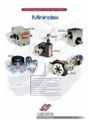
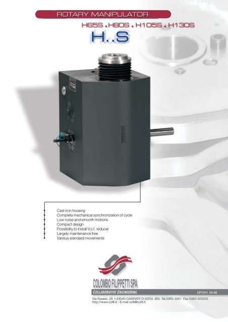
• Cast iron housing• Complete mechanical synchronization of cycle• Low noise and smooth motions• Compact design• Possibility to install V.s.f. reducer• Largely maintenance free• Various standard movementsCF1311 09-06Via Rossini, 26 I-24040 CASIRATE D’ADDA -BG -Tel 0363-3251 Fax 0363-325252http://www.cofil.it - E-mail cofil@cofil.it
H..SMANIPULATORINTERMICO manipulators of the H..S series are compactly designeddevices with positive- locking, hardened and ground cams.A globoid cam and a plate cam serve pendulum gear serve as drivingelements.The movements of the gripper arm follow a circular path. The device isavailable in the form of a lifting-stepping model or a lifting-oscillating model.0
H..SMANIPULATORContentsPAG1. General.............................................................................22. Danger zone ......................................................................23. Application examples of INTERMICO H..S manipulators ............34. Selecting the right type .......................................................45. Installation instructions .......................................................46. Start-up............................................................................57. Maintenance instructions.....................................................58. Models .............................................................................69. Mounting positions for external reducing gears.......................710. Movement sequences .........................................................811. Determining the type designation ........................................1012. Data and parameters........................................................1113. Dimensions......................................................................1214. Run-out and concentricity tolerances...................................1415. Static load capacities ........................................................1416. Built-in worm gear ............................................................1517. Worm gear transmission ratios ..........................................1518. Mounting surfaces for electric motors ................................1619. Mounted worm gears (RMI model) ......................................1620. Mounting of control microcam............................................1721. Control microcams for limit switches / gripper control ..........1722. Dimensions of oil gauge holes .............................................1823. Oil volumes ......................................................................1824. Slewing bearings (on request; obligatory for A1 movementsequences) ......................................................................1925. Accessories, optional features ...........................................20The units of measurement correspond with System International /Severity Index SI General tolerances ofmanufacture are conform to UNI – ISO 2768-1 UNI EN 22768-1Illustrations and drawings according to UNI 3970 (ISO 128-82).Method of projection of the drawings.All rights reserved. No part of this catalogue may be duplicated.COLOMBO FILIPPETTI may make any changes they feel necessary for the improvement of their productswithout advance notice.COLOMBO FILIPPETTI may change any market components and accessories mentioned in this catalogue asthey feel necessary.This catalogue supersedes all earlier ones.1
H..SMANIPULATOR1. GeneralINTERMICO manipulators of the H..S series have a gray cast iron housing. The cams operate in an oil bath.An output shaft through hole for passing services, is an option, the hole rotates.A protective device is provided to keep out water and dirt.1.1 What are the advantages of INTERMICO H..S manipulators?- compact design - high cycle speeds- short switching times - largely maintenance-free- positive locking - central through hole (on request)- low noise - various drive options- long life - no additional indexing required1.2 Where are INTERMICO H..S manipulators used?These manipulators can be used wherever parts need to be moved with short switching times and smoothseries of motions along circular paths, e.g. in assembly lines, welding plants, transfer lines, loading andunloading equipment, pallet changers, feeders, etc.1.3 How does an INTERMICO H..S manipulator work?During a moving sequence, the driven flange of the manipulator performs both intermittent or oscillatingmovements and lifting and lowering movements. This driven flange is connected to the driving elements vialifting shafts so as to ensure positive engagement with the generating cams at all times. The intermittent oroscillating motion of the driven flange is effected via a globoid gear, and the lifting motions via a positivelocking plate cam drive.The manipulator is driven either via the cam shaft or via a built-in worm drive. One full rotation of the camshaft generates a complete cycle, which consists of motional and dwell phases.0DriveDegrees 0360DriveDegrees360s v aDiagram of lifting motionFig. 1s v aDiagram of stepping motion2. Danger zoneThis being a positive-locking device, a mounted gripper arm will move constantly within its set range. It willonly be arrested due to overloading of the drive motor or safety clutch if installed, or to breakage.The danger zone is not exceeded, however.2
H..SMANIPULATOR3. Application examples of INTERMICO H..S manipulatorsIn many applications, you will find that, by using two or more arms with grippers, it is possible to load andunload simultaneously at high speed. By adding more dwell positions, it is also possible to perform otherfunctions together with the loading and unloading operations.INTERMICO manipulator as a workpiece feederFig. 2INTERMICO manipulator as a transfer deviceFig. 3Fig. 4INTERMICO manipulator in an insertion system. It has an additional drive for the transfer movement of aconveyor belt.3
H..SMANIPULATOR4. Selecting the right typeIn order to select the right type of INTERMICO H..S manipulator, it is not sufficient to simply calculate themass moment of inertia and lifting load and then determine the size of the INTERMICO manipulatoraccordingly.In the case of cam-controlled manipulators, the ratio of the total inertial radius to the geometrical radius ofthe installed globoid gear is also a decisive factor.We recommend that you get our Technical Office to calculate the right type of INTERMICO manipulator foryou. For this purpose, please use the questionnaire at the end of the catalog, enclosing any relevantsketches or drawings.If the values of D max.perm. and r max.perm. (page 11) are exceeded, the dimensioning of the manipulatorshould in all cases be left to our Technical Office.5. Installation instructionsUsing a brake motor INTERMICO manipulators of the series H65S,H80S, H105S and H130S can be installed in any orientation. Theycan be fixed to prevent torsion and displacement by means of keyslots and a centering device in plane A.Plane A5.1 Using a brake motorFig. 5A brake motor is used if the dwell phase is to be prolonged. In this case, the length of the phase time isgoverned by the switching off of the brake motor.In order to move the manipulators easily into position during setting operations or when starting up againafter malfunctions, we recommend that you use brake motors with manual release and a second shaft endwith a handwheel.5.2 Instructions for setting the control microcamIf a brake motor is used to drive an INTERMICO manipulator, the control microcam which causes the brakemotor to stop must be set so that the drive shaft comes to a standstill in the middle of a dwell period.Driven flangeCam shaftFig. 6Mounting of control cam on an INTERMICOmanipulator driven by a brake motorIn the position shown, the mark on the end of thecam shaft or key is in the middle of a dwell period4
H..SMANIPULATOR5.3 Instructions for trouble-free operationElastic elements must be avoided at all costs in the drive train. Use only torsionally rigid elements. Use onlyhardened parallel pins to connect attachment devices, e.g. grippers. Screw fittings should be secured with ascrew retention fluid.Regular stopping of the INTERMICO manipulator when in motion period should be avoided to preventdamage to the device. If an inching control facility is provided for setting operations or if frequent emergencystops are likely during the movement phase, this must be taken into account in the design.6. Start -upAll INTERMICO manipulators are supplied without oil and should be filled with a lubrication oil specified bythe industrial standard DIN 51517 Part 3 Group CLP. The following is a list of some types of oil which complywith ISO VG 150.AGIP Blasia 150BPEnergol GR-XP-150CASTROL Alpha SP 150CHEVRON NL Gear Compound 150ESSO <strong>Spa</strong>rtan EP 150FINA Giran 150MOBIL Mobilgear 629SHELL Omala Oil 150TOTAL Carter EP 150Take care to ensure cleanliness during the filling procedure. We recommend that you use a filter or finesieve.See page 18 for oil quantities.7. Maintenance instructionsINTERMICO H60G manipulators require no maintenance except for checking of the oil level. This check isperformed via the oil-level gauges. If the oil level falls below the prescribed minimum, it must be topped upthrough the charging hole.If frequent top-ups are necessary, the cause should be investigated and rectified immediately.7.1 Changing the lubricating oilThe oil should be changed according to the following procedure after 8000 operating hours, or 2 years at thelatest:• Unscrew drain plug• Drain off oil completely and screw drain plug back in place• Top up to the prescribed level through the charging hole7.2 General inspectionThe INTERMICO manipulator must be inspected every 8000 operating hours for excessive radial play of therollers; if necessary, all rollers must be changed simultaneously.In this case, please contact us.5
H..SMANIPULATOR8. ModelsH60G INTERMICO manipulators are available in the following models:GSManipulator driven directly via cam shaftGUManipulator with reducing gear on cam shaftGU1 ⎤ Manipulator with built-in worm gear andGU2 ⎦ free drive shaftGUFManipulator with reducing gear and flange for mounting electric motorsGUF1 ⎤ Manipulator with built-in worm gear andGUF2 ⎦ flange for mounting electric motorsGMManipulator with gear motorGM1 ⎤ Manipulator with built-in worm gear andGM2 ⎦ motorGBManipulator with transmission brake motorGB1 ⎤ Manipulator with built-in worm gear andGB2 ⎦ brake motorGSGU GU 1 GU 2GUF GUF 1 GUF 2GMGBGM 1 GM 2GB 1 GB 2Fig. 76
H..SMANIPULATOR9. Mounting positions for external reducing gearsThe INTERMICO GS model manipulators can be equipped with external worm gears with a slipping overloadclutch. By using different gear reductions, it is possible to obtain a range of 7 to 50 shifts per minute. Thegears can be mounted in 16 different positions. When ordering, the following details are necessary inaddition to the required mounting position:− The transmission ratio of the worm gear or the number of cycles per minute performed by the manipulator incontinuous operation− The IEC dimensions of the motor flange, if the gear is to be supplied without amotor− The motor ratings (power, number of poles, voltage, frequency)If the gears are to be equipped with drives other than the one described, e.g. clutch-brake combinations,infinitely variable speed gears, etc., we will be happy to supply these too.Gears in plane "E"Gears in plane "F"71758185727682867377838774788488Fig. 87
H..SMANIPULATOR10. Movement sequences10.1. Lifting-stepping modelMovement sequence A1Movement sequence A2XX0360 00YY0 360 00360 0360 0Diagram of movementsA12 - stationsFig. 9Diagram of movementsA22 - stations3 - stations3 - stations4 - stations4 - stationsOther stations on requestFig. 10IMPORTANT: In the case of A1 movement sequences (rotation in extended position), the devices aresupplied with an additional slewing bearing.(See page 19 for an additional slewing bearing)8
H..SMANIPULATOR10.2. Lifting-oscillating modelMovement sequence A1Movement sequence A2XXY0 0360 0 0360 0360 0Y0 360 0Fig. 11Diagram of movementsDiagram of movementsXYXYFig. 12IMPORTANT:In the case of A1 movement sequences (pivoting in extended position), thedevices are supplied with an additional slewing bearing.(See page 19 for an additional slewing bearing)9
H..SMANIPULATOR11. Determining the type designationThe type designation of INTERMICO H..S manipulators is made up of alphanumeric groups as shown in thetable below1 2 3 4 5SeriesNumber of stations (lifting-stepping)Angle of oscillation (lifting-oscillating)Stroke in mmMovement sequenceModel1 Plane with cam shaft2 Plane with mounting holes3 Plane with oil level gauge4 Bottom plane after installation5 Plane for mounting control camsMounting position of external reducing gearPossible plane combinationsPlanes A B C D E F 0EBC1 Plane with cam shaftF2 Plane with mounting holes3 Plane with oil level gaugeD4 Bottom plane after installation5 Plane for mounting control camsAOther plane combinations on requestPlane 0: cam shaft does not protrudeFig. 13Example of a type designation for an H65S series manipulator, 4 stations, 60 mm stroke, A2 movementsequence, housing with built-in worm gear and braking motorIn order to identify an H..S manipulator, the required code letters and positions must be added to the ordernumber.Manipulator H65S-4-60-A2-GB1-10-2A-3F-4A-5F10
H..SMANIPULATOR12. Data and parameters12.1 Lifting-stepping modelTab. 112.2 Lifting-oscillating modelTab. 2Number Max. output Pivoting Max. outputSeries of torque of rotation axis Series angle torque of rotation axisstations Nm (°) NmH 65 S 2 220 H 65 S 90 180Max stroke 3 220 Max stroke60 mm 4 220 60 mmH 80 S 2 390 H 80 S 90 250Max stroke 3 590 Max stroke90 mm 4 360 90 mmH 105 S 2 820 H 105 S 90 510Max stroke 3 1390 Max stroke120 mm 4 780 120 mmH130 S 2 1470 H 130 S 90 1100Max stroke 3 2250 Max stroke160 mm 4 1200 160 mmMaximum values shown for n= 30 rpmMaximum values shown for n= 30 rpm12.3. Permissible diameters and radii of attachmentsTab. 3Series D max.perm. r max.perm.H 65 S < 0.60 m < 0.30 mH 80 S < 0.80 m < 0.40 mH 150 S < 1.10 m < 0.55 mH 130 S < 1.40 m < 0.70 mFor details of permissible lifting loads (grippers and workpieces) in conjunction with the relevant arm length,please do not fail to contact our Technical Office.11
H..SMANIPULATOR13. DimensionsDriven flange Center of stroke marked Through holesfor mountingStrokeCam shaftFig. 1412
H..SMANIPULATORTab. 4Series A B C D E F G K L Mj6 O P ∅Qk6 RH 65 S 333 232 300 187 60 127 90 132 118 100 206 127 28 65H 80 S 420 300 380 232 75 163 110 155 140 116 255 165 30 85H 105 S 534 370 434 346 105 179 145 168 152 136 329 205 38 85H 130 S 645 460 550 328 125 235 185 180 160 140 410 235 50 115Series S T U V Z A1 B1 C1 D1 E1 F1 H1 J1 O1H7H 65 S 60 90 63 12 69 30 273 212 10 10 167 45° M6 78H 80 S 80 110 80 12 92 30 360 275 12.5 12.5 205 45° M6 100H 105 S 80 145 100 16 112 35 464 335 17.5 17.5 308 45° M8 115H 130S 110 185 140 13 135 40 565 424 18 20 290 45° M8 140Series P1 Q1 R1 S1 H7 T1 U1H 65 S 4 13 67 16 6 32H 80 S 4 14 83 16 6 32H 105 S 4 16 107 16 6 32H 130 S 4 15 145 16 6 32Series K1 L1; DIN6885,p.1 M1 Centering ∅V1H8 Max. strokeH 65 S M10;16tief 8x7x56 M10;22tief 47;5tief 60H 80 S M10;16tief 8x7x70 M12;28tief 50;6tief 90H 105 S M12;20tief 10x8x75 M12;28tief 55;2tief 120H 130 S M12;25tief 14x9x100 M16;36tief 52;10tief 160BoreholesBoreholesFig. 15Position of tap holes as shown: with stepping: in the middle of a holding notchwith oscillation: in the middle of an oscillationTab. 5Series P n x 0° ∅r Hole circle m BoreholesH 65 S 4 8 x 45° 100 h7 108 ± 0.1 M6,8 deepH 80 S 2 8 x 45° 130 h9 145 ± 0.1 M6,8 deepH 105 S 2 8 x 45° 136 j6 148 ± 0.1 M8,9 deepH 130 S 2 8 x 45° 160 h7 180 ± 0.1 M6,8 deep13
H..SMANIPULATOR14. Run-out and concentricity tolerancesRun-outFig. 16ConcentricityTab. 6Series Run-out ConcentricitH 65 S 0.07 0.10H 80 S 0.07 0.10H 105 S 0.10 0.15H 130 S 0.10 0.1515. Static load capacitiesFaMnFrMtFig. 17Tab. 7H 65 S H 80 S H 105 S H 130 SSeries Load Load Load Load Load Load Load Loadretracted extended retracted extended retracted extended retracted extendedFa (N) 600 750 1100 1400Fr (N) 3200 1000 4000 900 8200 1200 9200 700Mn (Nm) 100 80 160 100 340 160 380 120Mt (Nm) 180 250 510 1100Attention! The values indicated are maximum values for each individual load. If more than one loadacts simultaneously, please contact our technical office.14
H..SMANIPULATOR16. Built-in worm gearDrive shaftGU 1GUF 1GU 2 GUF 2Fig. 18Tab. 8SeriesA2DIN 6885, Bl. 1B2 C2 D2 ∅E2k6 ∅F2 G2 H2 ∅J2 ∅K2 L2 M2 Flange sizeH 65 S 5x5x18 18 26 64 16 6.6 62 64 120 100 64 64 C120H 80 S 6x6x30 24 35 85 20 9 78 85 140 115 83 83 C140H 105 S 8x7x30 43 35 105 28 9 106 105 160 130 79 79 C160H 130 S 10x8x50 49 58 95 38 9 116 95 160 130 95 95 C160Other flange sizes on request17. Worm gear transmission ratiosTab. 9Series Transmission IH 65 S 6 12 19 26 34 4863 70H 80 S 6.75 12 20 30 50 80H 105 S 6.75 9.25 (12.25) 14.5 19.5 (26)29 39 (52) 62 82H 130 S 5.33 6.8 8.75 10.67 13.33 16.520.5 25.5 32 41 51 64The worm gears are right-handed unless otherwise specified15
H..SMANIPULATOR18. Mounting surfaces for electric motorsCAFig. 19Tab. 10Series Size of electric motors according to DIN 426/7H 65 S 80H 80 S 90S / 90LH 105 S 100L / 112MH 130 S 100L / 112MOther motor sizes on request.19. Mounted worm gears (RMI model)with permanently adjusted LCB slipping overload clutchTab. 11Fig. 20Series B C D F H I K N P YB5* YB14* Z* Largest possiblegearboxH 65 S 101 62 28 160 130 70 97 92 56 A200 C120 19 RMI 70H 80 S 100 75 32 200 165 85 116 111 60 A200 C140 24 RMI 85H 105 S 131.5 94.5 42 270 230 110 145 142 90 A250 C160 28 RMI 110H 135 S 131.5 94.5 42 270 230 110 145 142 90 A250 C160 28 RMI 110Transmission ratios: 7, 10, 15, 20, 28, 40, 49, 56, 70, 80, 10016
H..SMANIPULATOR20. Mounting of control microcamThe shape of the cam depends on the type of limit switch.Microcam position can beadjusted on shaft as requiredSwitch mounting plateTab. 12Fig. 21Series ∅d f g h i k lH 65 S 16 78 15 5 15 60 80H 80 S 16 77 16 5 15 60 80H 105 S 16 77 17 5 15 60 80H 130 S 16 80 14 5 15 80 12021. Control microcams for limit switches / gripper controlproximitywith push type with roller lever (contactless)D4B 1171-DIN 43694 forma B D4B 1111-DIN 43694 forma A/B E2E2 - X2B1 o TLE-X5BI-GFig. 2217
H..SMANIPULATOR22. Dimensions of oil gauge holesPlane E/FView APlane APlane DAPlane BPlane CFig. 23The oil gauge holes also accommodate suitable ventilating filters and plug screws in all installation positions.Tab. 13Series a b c d e f g h iH 65 S 85 248 62.5 160 60 172 70 162 R 3/8"H 80 S 90 352 65 215 80 220 96 204 R 1"H 105 S 110 446 95 224 120 250 120 250 R 1"H 130 S 116 545 85 320 100 360 140 320 R 1"(Oil level gauges and plug screws are countersunk in all devices; ventilating filters project as follows: H65S:12 mm, H80S H130S: 19 mm)23. Oil volumesTab. 14Series Bottom plane after installationAB, C, D, E, FH 65 S 6.5 7.5H 80 S 19.5 21H 105 S 32 34H 130 S 45 48Values indicated in litres (rounded off)18
H..SMANIPULATOR24. Slewing bearings (on request; obligatory for A1 movementsequences)hdTab. 15Series dmax hmaxH 65 S 264 90H 80 S 350 120H 105 S 370 145H 130 S 570 185Fig. 2419
H..SMANIPULATOR25. Accessories, optional features25.1. Rotary turnover module 25.2. Gripper armFig. 25 Fig. 26Central borehole (co-rotating)d1hd2bFig. 27Tab. 16Size b d1 d2 hH 65 S 217 M20x1.5 10 121H 80 S 273 M20x1.5 12 156H 105 S 324 M27x1.5 15 186H 130 S 420 M27x1.5 15 23320
AGENTSitalian european overseasCOLOMBO FILIPPETTI Torino S.r.l.Via Massimo D’Antona,65I-10040 RIVALTA DI TORINO (TO)Tel. +39 011 3972211Fax +39 011 3497863E-mail: info@cofilto.ithttp://www.cofilto.itRDB RIZZARDI S.r.l.Via Massimo D’Antona,65 - Fraz. PastaI-10040 RIVALTA DI TORINO (TO)Tel. +39 011 3989546Fax +39 011 3497863E-mail: rdb@cofil.itE-mail: rdb.rizzardi@gmail.comCOLOMBO FILIPPETTI SPASUCCURSALE FRANCEFranceBp 14-2 Rue de BâleF-68180 HORBOURG WIHR CEDEXTel. +33 3 89216867Fax +33 3 89216999E-mail: cofil@cofil.frhttp://www.cofil.frMIKSCH GMBHGermanyReutlinger Strasse 5D-73037 GÖPPINGENTel. +49 7161 67240Fax +49 7161 6724-97E-mail: miksch@miksch.dehttp://www.miksch.deGEAREX CORPORATIONTaiwanNO.13, TA TUNG 1ST RD.,KUAN YIN IND,PARK,TAOYUAN HSIEN TAIPEITel. +886 26322856Fax +886 34831427E-mail: trans888@ms27.hinet.nethttp://www.gearex.com.twINDEXING TECHNOLOGIES INC.U.S.AP.O. BOX 252,37 Orchard St.RAMSEY, N.J. 07446-0252Tel. +1 201 9346333Fax +1 201 9346488E-mail: info@indexingtechnologies.comhttp://www.indexingtechnologies.comTECNOCAMMEVia Panigale,11I-40132 BolognaTel. +39 051 6415568Fax +39 051 6419072E-mail: tecnocamme@cofil.itMOTION TECH SRLP.zza S.Giovanni Battista,15-1I-35035 LISSARO di MESTRINO PDTel. +39 049 9004214Fax +39 049 9004214E-mail: motion.tech@cofil.itWIDE AUTOMATION SRLVia Malpasso,1340I-47842 S.GIOVANNI IN MARIGNANO RNTel. +39 0541 827200Fax +39 0541 825021E-mail: info@wideautomation.ithttp://www.wideautomation.itPRECISION MOTION (COFIL) LTDGreat BritainPO Box 2034Preston - LancashirePR5 9ADTel. +44 (0)1772 339633Fax. +44 (0)1772 336362Email : stuart@precisionmotion.co.ukhttp://www.precisionmotion.co.ukCUBYTRANSMISION DE POTENCIA S.L.<strong>Spa</strong>inC/Permanyer,34E-08205 SABADELL BarcellonaTel. +34 93 7451950Fax +34 93 7255079E-mail: info@cuby.eshttp://www.cuby.esPRECISION INTERNATIONALIndia108,Aashirwad,Green Park (Main)NEW DELHI-110016Tel. +91 11 26561687Fax +91 11 26851390E-mail: precinter@vsnl.comhttp://www.precinter.comCM ENGINEERINGVia Della Pineta,34I-65129 PESCARA PETel. +39 085 7998879Tel. +39 333 1035570Fax +39 1782766858E-mail: cmengineering@cofil.ithttp://www.cmengineering.itAGENZIA RDSZona ind.le localita’ PozzobiancoI-81025 MARCIANISE CEmobile +39 0823 451233Fax +39 0823 1780114mobile +39 335 1289960E-mail: raffaele.desimone@agenziards.comhttp://www.agenziards.com