SM 25 - Plastorgomma
SM 25 - Plastorgomma
SM 25 - Plastorgomma

You also want an ePaper? Increase the reach of your titles
YUMPU automatically turns print PDFs into web optimized ePapers that Google loves.
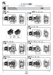
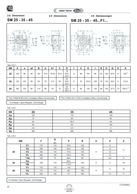
2.8 Dimensioni 2.8 Dimensions<br />
2.8 Abmessungen<br />
<strong>SM</strong> <strong>25</strong> - 35 - 45<br />
<strong>SM</strong> <strong>25</strong> - 35 - 45...F1...<br />
Tab. 2.8.1<br />
<strong>SM</strong> A a a2 B b b1 C D f h H I N O Q S K<br />
<strong>25</strong> 122 90 45 90 73.5 16,55 52.5<br />
35 130 100 50 95 75 17.5 60<br />
45 165 120 60 110 90 19 70<br />
19<br />
(20*)<br />
(24*)<br />
<strong>25</strong><br />
(28*)<br />
(30*)<br />
30<br />
(<strong>25</strong>*)<br />
(28*)<br />
9 65 107 90 65 122 <strong>25</strong>.5 8 100 (1)<br />
9 70 123.5 100 70 130 28.5 8 122.5<br />
9 80 130 120 80 155 27.5 10 129.5 (2)<br />
(1) Per il PAM 90 B5 e B14 contattare Ufficio Commerciale<br />
(2) Per il PAM 100-112 B14 contattare Ufficio Commerciale<br />
* A richiesta / Upon Request / Auf Anfrage<br />
Tab. 2.8.2<br />
<strong>SM</strong> <strong>25</strong> 35 45<br />
Fp 100 110 120<br />
Gp 70 80 80<br />
Pp 50 55.5 65<br />
Rp 85 95 100<br />
Up 2.5 2.5 3<br />
Vp M8 M8 M8<br />
Tab. 2.8.3<br />
<strong>25</strong><br />
35<br />
45<br />
<strong>SM</strong><br />
F<br />
G<br />
(g6)<br />
P R U V Z<br />
F1 175 115 78.5 150<br />
11<br />
F2 200 130 94.5 165 13<br />
F3 160 110 74.5 130 5<br />
10<br />
11<br />
FL 200 130 103.5 165 13<br />
* FA 1<strong>25</strong> 70 96.5 85 8.5 9<br />
FA<br />
84.5<br />
180 115<br />
FB 114.5<br />
150 6 11 10<br />
F1 175 115 116 150<br />
F2 175 115 85 150<br />
5<br />
11 10<br />
FL 200 130 111 165 13 11<br />
* A richiesta / Upon Request / Auf Anfrage<br />
22<br />
CT22IGBD3
ALBERO LENTO CAVO E ALBERO<br />
CALETTATORE<br />
Per l’utilizzazione corretta del riduttore e del<br />
calettatore eseguire il dimensionamento<br />
dell’albero lento standard e dell’albero lento<br />
per calettatore come indicato nelle seguenti<br />
figure.<br />
Tab. 2.8.4<br />
OUTPUT SHAFT AND OUTPUT SHAFT<br />
SHRINK DISC<br />
Below there are listed the internal<br />
dimensions of the output shaft with keyway<br />
and with shrink disc.<br />
To guarantee best performance we<br />
recommend for the shafts of the clients the<br />
dimensions also shown below.<br />
ABTRIEBSWELLEN<br />
Unten sind die Abmessungen der<br />
Abtriebshohlwellen in Paßfederu.<br />
Schrumpfscheibenausführung aufgeführt.<br />
Für eine bestmögliche Leistung empfehlen<br />
wir für die Wellen der Kunden die ebenfalls<br />
aufgeführten Abmessungen.<br />
S<br />
<strong>SM</strong><br />
C<br />
Ca<br />
<strong>25</strong> 52.5 100<br />
35 60 120<br />
45 70 140<br />
D<br />
H7<br />
19<br />
(20*) (24*)<br />
<strong>25</strong><br />
(28*) (30*)<br />
30<br />
(<strong>25</strong>*) (28*)<br />
Albero lento cavo<br />
Output shaft with keyway<br />
Abtriebswelle mit passfedernut<br />
M1 M2 De<br />
<strong>25</strong> <strong>25</strong> 35<br />
30 30 45<br />
* A richiesta / Upon Request / Auf Anfrage<br />
S<br />
<strong>SM</strong><br />
<strong>25</strong><br />
35<br />
45<br />
Cc<br />
D<br />
H7<br />
Alberolento cavo con calettatore<br />
Output shaft with shrink disc<br />
Abtriebswelle mit schrumpfscheibe<br />
m1 m2 g Gg<br />
Contattare il ns. servizio tecnico<br />
Contact our technical dept<br />
Wenden Sie sich an unseren technischen Service<br />
sx<br />
dx - standard<br />
ALBERO LENTO BISPORGENTE DOUBLE OUTPUT SHAFTS<br />
HOHLWELLE MIT DOPPELTEM<br />
WELLENENDE<br />
Tab. 2.8.5<br />
ALBERO INTEGRALE<br />
INTEGRAL SHAFT<br />
INTEGRALWELLE<br />
S..45<br />
CT22IGBD3<br />
23
2.9 Accessori 2.9 Accessories<br />
2.9 Zubehör<br />
BRACCIO DI REAZIONE [T]<br />
Per il fissaggio del riduttore mediante<br />
tirante, viene fornito in allegato l’apposito<br />
braccio di reazione.<br />
Tab. 2.9.1<br />
TORQUE ARM [T]<br />
If the gearbox shall be shaft mounted as an<br />
extra part there is also available a torque<br />
arm.<br />
DREHMOMENTSTÜTZE [T]<br />
Soll das Getriebe pendelnd gelagert<br />
werden, so ist als Zubehörteil auch eine<br />
Drehmomentstütze.<br />
S<br />
<strong>SM</strong><br />
BRACCIO DI REAZIONE [T]<br />
TORQUE ARM [T]<br />
DREHMOMENTSTÜTZE [T]<br />
A G H I Iv Pr R<br />
<strong>25</strong> 100 15 10 4 5 40.5 <strong>25</strong><br />
35* 150 15 10 6 5 50 <strong>25</strong><br />
45 150 20 10 6 5 58 30<br />
* Solo Con Boccola in VKL / With VKL bushing<br />
Alberi lenti<br />
Output shafts<br />
Abtriebswellen<br />
Tutti i riduttori sono forniti con albero lento<br />
cavo. A richiesta, possono essere forniti kit<br />
di montaggio per alberi sporgenti<br />
comprensivi di linguette, rondelle e viti di<br />
fissaggio. Le dimensioni delle linguette<br />
sono conformi alle norme UNI 6604-69.<br />
All gearboxes are supplied with hollow<br />
output shaft. On request there are available<br />
also assembly kits including output shafts,<br />
keys, washers and assembly screws. The<br />
dimensions of the keys are conform with<br />
UNI 6604-69.<br />
Alle Getriebe werden mit Abtriebshohlwelle<br />
geliefert. Auf Anfrage sind auch Montagekits<br />
inklusive Abtriebswellen, Paßfedern,<br />
Unterlegscheiben und Montageschrauben<br />
erhältlich. Die Abmessungen der<br />
Paßfedern sind konform mit der UNI<br />
Albero lento<br />
Single output shaft<br />
Einseitige Abtriebswelle<br />
Albero lento bisporgente<br />
Double output shaft<br />
Beidseitige Abtriebswelle<br />
S.. - <strong>SM</strong>..<br />
<strong>25</strong> 35 45<br />
A 80 109 140<br />
B 10 10 3<br />
C 40 60 60<br />
d2 g6 19 <strong>25</strong> 30<br />
m2 M8 M8 M10<br />
E 22 34 36<br />
F 105 112 Albero Integrale<br />
G 41 70 Albero Integrale<br />
L <strong>25</strong> 40 50<br />
L1 40 60 80<br />
X 8 10 5<br />
Y 21 30 42.5<br />
24<br />
CT22IGBD3
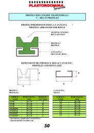
2.10 Linguette<br />
2.10 Keys 2.10 Paßfedern<br />
Albero Entrata - Input Shaft - Antriebswelle<br />
SR<br />
<strong>SM</strong><br />
PAM B5<br />
<strong>SM</strong><br />
PAM B14<br />
d b 1 t 1<br />
9 3 10.2<br />
11 4 12.5<br />
14 5 16.0<br />
16 5 18.0<br />
18 6 20.5<br />
19 6 21.5<br />
24 8 27.0<br />
<strong>25</strong> 8 28.0<br />
28 8 31.0<br />
30 8 33.0<br />
32 10 35.0<br />
35 10 38.0<br />
38 10 41.0<br />
42 12 45.0<br />
+ 0.1<br />
0<br />
+ 0.2<br />
0<br />
PAM<br />
B5<br />
Y dY bY tY<br />
56 120 9 3 10.4<br />
63 140 11 4 12.8<br />
71 160 14 5 16.3<br />
80 200 19 6 21.8<br />
90 200 24 8 27.3<br />
100 <strong>25</strong>0 28 8 31.3<br />
112 <strong>25</strong>0 28 8 31.3<br />
132 300 38 10 41.3<br />
160 350 42 12 45.3<br />
180 350 48 14 51.8<br />
200 400 55 16 59.3<br />
+ 0.1<br />
0<br />
+ 0.2<br />
0<br />
PAM<br />
B14<br />
Y dY bY tY<br />
56 80 9 3 10.4<br />
63 90 11 4 12.8<br />
71 105 14 5 16.3<br />
80 120 19 6 21.8<br />
90 140 24 8 27.3<br />
100 160 28 8 31.3<br />
112 160 28 8 31.3<br />
132 200 38 10 41.3<br />
+ 0.1<br />
0<br />
+ 0.2<br />
0<br />
45 14 48.5<br />
48 14 51.5<br />
50 14 53.5<br />
55 16 59.0<br />
65 18 69.0<br />
Albero Uscita - Output Shaft - Abtrieswelle<br />
Albero Forato<br />
S - SR - <strong>SM</strong><br />
Albero Pieno<br />
S - SR - <strong>SM</strong><br />
D b 2 t 2<br />
14 5 16.3<br />
18 6 20.8<br />
19 6 21.8<br />
24 8 27.3<br />
<strong>25</strong> 8 28.3<br />
28 8 31.3<br />
30 8 33.3<br />
32 10 35.3<br />
35 10 38.3<br />
42 12 45.3<br />
45 14 48.8<br />
48 14 51.8<br />
50 14 53.8<br />
55 16 59.3<br />
65 18 69.4<br />
+ 0.1<br />
0<br />
+ 0.2<br />
0<br />
d 2 b 2 t 2<br />
9 3 10.2<br />
11 4 12.5<br />
14 5 16.0<br />
16 5 18.0<br />
18 6 20.5<br />
19 6 21.5<br />
24 8 27.0<br />
<strong>25</strong> 8 28.0<br />
28 8 31.0<br />
30 8 33.0<br />
32 10 35.0<br />
35 10 38.0<br />
38 10 41.0<br />
42 12 45.0<br />
45 14 48.5<br />
48 14 51.5<br />
+ 0.1<br />
0<br />
+ 0.2<br />
0<br />
50 14 53.5<br />
55 16 59.0<br />
65 18 69.0<br />
CT22IGBD3<br />
<strong>25</strong>
2.0 RIDUTTORI - MOTORIDUTTORI ORTOGONALI AD ASSI SGHEMBI<br />
2.0 THE SKEW BEVEL HELICAL GEARBOXES WITH SKEW AXIS<br />
2.0 DIESE GETRIEBEMOTORE SIND MIT ZWEI SPIRALSTIRNRADSTUFEN MIT SCHRAEGE<br />
ACHSEN HERGESTELLST<br />
S<br />
2.1 Caratteristiche tecniche Technical characteristics Technische Eigenschaften 14<br />
2.2 Designazione Designation Bezeichnungen 14<br />
2.3 Versioni Versions Ausführungen 15<br />
2.4 Lubrificazione Lubrication Schmierung 16<br />
2.5 Posizioni di montaggio Mounting positions Montagepositionen 16<br />
2.6 Carichi radiali e assiali Axial and overhung loads Radiale und Axiale Belastungen 17<br />
2.7 Prestazioni riduttori Gearboxes performances Leistungen der Getriebe 18<br />
2.8 Dimensioni Dimensions Abmessungen 20<br />
2.9 Accessori Accessories Zubehör 22<br />
2.10 Linguette Keys Paßfedern 22<br />
Pag.<br />
Page<br />
Seite<br />
CT22IGBD3<br />
13
2.1 Caratteristiche tecniche<br />
La progettazione di questi riduttori è stata<br />
impostata su una struttura monolitica particolarmente<br />
rigida che permette l’applica zione<br />
di elevati carichi.<br />
I riduttori – motoriduttori sghembi ortogonali<br />
sono realizzati con due stadi di riduzione ad<br />
ingranaggi cilindrici elicoidali ad assi<br />
sghembi.<br />
Carcasse e flange sono realizzate in<br />
alluminio SG-AlSi UNI 1706.<br />
La lavorazione di tutte le carcasse avviene<br />
su moderni centri di lavoro a controllo numerico<br />
che permette di ottenere la massima<br />
precisione costruttiva.<br />
L’albero di entrata è realizzato in acciaio<br />
18NiCrMo5; quello in uscita in acciaio C40<br />
UNI 5332 o Fe 52 UNI7070. Tutti gli<br />
ingranaggi sono realizzati in acciaio<br />
18NiCrMo5 UNI 7846 cementati, temprati e<br />
rettificati per migliorarne il rendimento e la<br />
silenziosità anche sotto carico.<br />
2.1 Technical characteristics 2.1 Technische Eigenschaften<br />
The design of this series of gearboxes has<br />
been set up on a very rigid monolithic<br />
structure enabling the application of heavy<br />
loads.<br />
The skew bevel helical gearboxes<br />
incorporate two cylindrical helical reduction<br />
stages with skew axis.<br />
Housings and flanges are made of<br />
aluminium SG-AlSi UNI 1706.<br />
All the housings are manufactured in<br />
appropriately updated CNC centres<br />
working with numerical control so to ensure<br />
highest costructive accuracy.<br />
The input shaft is made steel 18NiCrMo5<br />
UNI EN 7846 and the output shaft is made<br />
of steel C40 UNI 5332 or Fe 52 UNI7070. All<br />
gears are made of steel 18NiCrMo5 UNI<br />
7846, previously casehardened, hardened<br />
and rectified to improve efficiency and<br />
quietness even under load.<br />
Der Entwicklung dieser Getriebeserie wurde<br />
eine monolithische Gehäusestruktur zugrunde<br />
gelegt.<br />
Diese Getribemotore sind mit zwei<br />
Spiralstirnradstufen mit schraege Aschsen<br />
hergestellst.<br />
Gehäuse und Flansche aus Maschinenguß<br />
SG-AlSi UNI 1706.<br />
Die Bearbeitung der Gehäuse erfolgt auf<br />
modernsten, numerisch gesteuerten Fertigungsmaschinen,<br />
wodurch eine hohe Fertigungsgenauigkeit<br />
und –qualität erzielt wird.<br />
Das Werkstoff der Eingangswelle ist<br />
18NiCrMo5 Stahl UNI 7846, die<br />
Ausgangswelle C40 Stahl UNI 5332 oder<br />
Fe 52 UNI 7070.<br />
Alle Zahnräder sind aus 18NiCrMo5 Stahl<br />
UNI 7846, gehärtet, einsatzgehärtet und<br />
geschliffen.<br />
Dies ermöglicht einen hohen Wirkungsgrad<br />
sowie einen geräuscharmen Lauf auch<br />
unter Last. Alle Kegelradgetriebe und–<br />
Getriebemotoren besitzen drei Untersetzungsstufen.<br />
2.2 Designazione 2.2 Designation<br />
2.2 Bezeichnung<br />
Grand.<br />
Size<br />
Größe<br />
Tipo<br />
Type<br />
Typ<br />
* 1 * 2 * 3 *4 ir IEC *5<br />
<strong>SM</strong><br />
S<br />
<strong>25</strong><br />
35<br />
45<br />
—<br />
F1<br />
F2<br />
FL<br />
FA<br />
FB<br />
(standard)<br />
-<br />
S<br />
—<br />
B<br />
C<br />
Diametro<br />
foro<br />
opzionale<br />
Optional<br />
hollow<br />
shaft<br />
diamete<br />
Optionaler<br />
Hohlwellen<br />
durchmess<br />
er<br />
—<br />
S<br />
Vedi tabelle<br />
prestazioni<br />
See<br />
performance<br />
tables<br />
Siehe<br />
Leistungstabellen<br />
44<br />
56(B5)<br />
...<br />
112(B5)<br />
CT18IGBD<br />
—<br />
B<br />
Specifiche: Specification: Spezifikationen:<br />
• [*1] Lato flangia uscita:<br />
Nessuna indicazione = flangia uscita con<br />
montaggio destro (flange dal lato come<br />
indicato nelle figure del catalogo);<br />
S = flange uscita con montaggio sinistro<br />
(flange dal lato opposto alle figure<br />
indicate a catalogo).<br />
• [*1] Mounting position output side:<br />
No indication (standard) = output flange<br />
on right side (like indicated in the figures);<br />
S = output flange on left side (flanges on<br />
the opposite side like indicated in<br />
figures).<br />
• [*1] Montageseite Abtriebsflansch:<br />
Keine Angabe (Standard) = Abtriebsflansch<br />
rechts (wie in den Abbildungen<br />
dargestellt)<br />
S = Abtriebsflansch links (gegenüber der<br />
Position in den Katalogabbildungen).<br />
14<br />
CT22IGBD3
2.2 Designazione<br />
2.2 Designations 2.2 Bezeichnungen<br />
• [*2] Albero uscita:<br />
Nessuna indicazione = albero forato;<br />
B = bisporgente integrale;<br />
C = albero forato con calettatore.<br />
• [*3] Diametro albero:<br />
Nessuna indicazione = diametro standard<br />
diametro foro opzionale=( tabella 2.2).<br />
• [*2] Output shaft:<br />
No indication = shaft with keyway;<br />
B = DOUBLE OUTPUT SHAFTS<br />
C = hollow shaft with shrink disk.<br />
• [*3] Shaft diameter:<br />
No indication = standard diameter<br />
optional diameters: see table 2.2.<br />
• [*2] Abtriebswelle:<br />
Keine Angabe = Hohlwelle mit Paßfedernut<br />
B=Hohlwelle Mit Doppeltem Wellenende;<br />
C = Hohlwelle mit Schrumpfscheibe.<br />
• [*3] Durchmesser Abtriebswelle:<br />
Keine Angabe = Standarddurchmesser<br />
Optionale Durchmesser: = s. Tabelle 2.2<br />
Tab. 2.2<br />
[*3]<br />
Grandezza<br />
Size<br />
Größe<br />
Standard<br />
albero forato<br />
shaft with keyway<br />
Hohlwelle mit Paßfedernut<br />
Su richiesta<br />
Upon Request<br />
Auf Anfrage<br />
albero forato con calettatore<br />
hollow shaft with shrink disk.<br />
Hohlwelle mit Schrumpfscheibe<br />
Standard<br />
Su richiesta<br />
Upon Request<br />
Auf Anfrage<br />
bisporgente integrale<br />
Double Output Shafts<br />
Hohlwelle Mit Doppeltem Wellenende<br />
Standard<br />
Su richiesta<br />
Upon Request<br />
Auf Anfrage<br />
<strong>25</strong> 19 20 24 <strong>25</strong> - - -<br />
35 <strong>25</strong> 28 30 30 - -<br />
45 30 28 <strong>25</strong> 35 - 30 -<br />
• [*4] Posizione calettatore (valido solamente<br />
per soluzione con calettatore):<br />
Nessuna indicazione = lato destro come<br />
indicato in figura Tab. 2.8.4 (standard);<br />
S = lato sinistro, montaggio dalla parte<br />
opposta alla figura Tab. 2.8.4(opzionale).<br />
• [*4] Mounting position of shrink disc:<br />
No indication (standard) = on right side,<br />
as showed in figure Tab. 28.4;<br />
S = on left side, on the opposite like<br />
indicated in figure Tab. 28.4.<br />
• [*4] Montageposition Schrumpfscheibe:<br />
Keine Angabe (Standard) = rechts (wie<br />
dargestellt in der Abbildung Tab. 2.8.4 );<br />
S =links (gegenüber der Position in der<br />
Abbildung Tab. 2.8.4).<br />
Altre specifiche: Further specification: Weitere Spezifikationen:<br />
• M1, M2, M3, M4, M5, M6 Posizioni di<br />
montaggio con indicazione dei tappi di<br />
livello, carico e scarico; se non<br />
specificato si considera standard la<br />
posizione M1 (vedi par. 2.4).<br />
• [T] Braccio di reazione.<br />
Braccio di reazione (vedi par. 2.9).<br />
• [2, 3, 4] Posizione della morsettiera del<br />
motore se diversa da quella standard (1).<br />
• M1, M2, M3, M4, M5, M6 Mounting<br />
position with indication of breatherm level<br />
and drain plugs; if not specified,<br />
standard position is M1 (see par. 2.4).<br />
• [T] Torque arm<br />
(see pa. 2.9).<br />
• [2, 3, 4] Position of the motor terminal<br />
box if different from the standard one (1).<br />
• Montageposition M1, M2, M3, M4, M5,<br />
M6 mit Angabe von . Entlüftung,<br />
Schaugläsern und Ablaßschraube.<br />
Wenn nicht näher spezifiziert, wird die<br />
Standardposition M1 zugrunde gelegt (s.<br />
Abschnitt 2.4).<br />
• [T] Drehmomentstütze<br />
(s. Abschnitt 2.9)<br />
• Montageposition Klemmenkasten [2, 3, 4],<br />
wenn abweichend von Standardposition<br />
[1] (für Motorgetriebe).<br />
• [*5] Bisporgenza Entrata:<br />
Nessuna indicazione = ingresso senza<br />
bisporgenza;<br />
B = entrata con bisporgenza.<br />
• [*5] Input double extension :<br />
No indication = no double extension<br />
B = input double extension<br />
• [*4] Doppelantrieb<br />
Keine Beschreibung= kein Doppelantrieb<br />
B= Doppelantrieb<br />
CT22IGBD3<br />
15
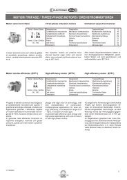
2.3 Versioni<br />
2.3 Versions 2.3 Ausführungen<br />
<strong>SM</strong>. (IEC)<br />
S..<br />
S..F..<br />
S..<br />
<strong>25</strong> 35 45<br />
F1 FA F1<br />
<strong>SM</strong>. (kW)<br />
(*) A richiesta / Upon Request / Auf Anfrage<br />
F..<br />
F2 FB F2<br />
F3 - FL<br />
FL - -<br />
*FA - -<br />
Posizione morsettiera<br />
Terminal board position<br />
Lage des Klemmenkastens<br />
• Senso di Rotazione<br />
• Rotation sense<br />
16<br />
CT22IGBD3
2.4 Lubrificazione 2.4 Lubrication<br />
2.4 Schmierung<br />
Il riduttore è fornito con olio sintetico del tipo<br />
(PAO) con elevato valore di adittivazione<br />
EP.<br />
Non immettere altra tipologia d’olio da<br />
quella indicata. Per ulteriori informazioni<br />
consultare il Nostro Ufficio Tecnico.<br />
Nella tabella Tab.2.4 sono riportati i<br />
quantitativi di olio necessari per il corretto<br />
funzionamento dei riduttori.<br />
Durante il riempimento attenersi ai<br />
quantitativi poiché in alcuni casi il livello del<br />
lubrificante oltrepassa la spia di livello.<br />
In fase di ordine specificare sempre la<br />
posizione di montaggio desiderata. Se<br />
omessa, il riduttore verrà fornito con i tappi<br />
predisposti per la posizione M1.<br />
The gearbox is supplied lubricated with<br />
synthetic oil (PAO) with a high percentage<br />
of additives EP. Make sure not to use any<br />
different oil type.<br />
For further informationplease refer to our<br />
Technical Office.<br />
In the chart Tab.2.4 the oil type and quantity<br />
recommended to obtain standard<br />
perfomances are given. When filling up<br />
please consider strictly the given quantities<br />
in some cases the lubrificant level line goes<br />
above the oil level plug. When ordering,<br />
please remember to specify the mounting<br />
position needed. If not given, the gearbox<br />
will be supplied with plugs pre-arranged for<br />
mounting position M1.<br />
Das Getriebe wird mit Ölfüllung (PAO)<br />
geliefert und keine andere Öltypen werden<br />
akzeptiert.<br />
Für weitere Auskünfte können sie sich an<br />
unsere Technische Abteilung wenden.<br />
Um die angegebene Leistung zu erreichen<br />
finden sie in der Tab.2.4 die empfohlenen<br />
Ölmenge und Öltype. Bei der Ölfüllung<br />
beachten sie bitte angegebene Menge, da<br />
in einigen Fälle die Ölstand Linie über den<br />
Ölstandstopfen geht. Bei Bestellungen<br />
bitte erinnern sie sich die Montage Position<br />
anzugeben. Wenn nicht angegeben wird<br />
das Getriebe mit Ölstopfen in<br />
Montageposition M1 geliefert.<br />
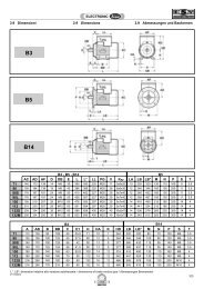
2.5 Posizioni di montaggio 2.5 Mounting positions<br />
2.5 Montagepositionen<br />
M1<br />
M1 M2 M3<br />
M6<br />
M3<br />
M4<br />
M5<br />
M2<br />
M4 M5 M6<br />
Carico / Breather plug / Einfüll-u. Entlüftungsschraube<br />
Livello / Level plug / Schauglas<br />
Scarico / Drain plug / Ablaßschraube<br />
Il tappo di sfiato è allegato su tutte le grandezze dei riduttori ed è necessario applicarlo prima della messa in servizio dello stesso.<br />
Breather plug is enclosed with every gearbox size and must be installed prior to operation<br />
.<br />
Der Entlüftungsstopfen wird mitgeliefert und muss vor der Benutzung des Getriebes eingebaut werden.<br />
Tab. 2.4<br />
<strong>SM</strong><br />
Quantità di lubrificante / Lubricant Quantity / Schmiermittelmenge (kg)<br />
Posizioni di montaggio /Mounting Positions / Montagepositionen<br />
M1 M2 M3 M4 M5 M6<br />
* n°. tappi olio<br />
* No.of plugs<br />
Anzahl Betriebschraube<br />
<strong>25</strong> 0.300 0.480 0.480 0.480 0.480 0.480 2<br />
35 Contattare il ns. servizio tecnico / Contact our technical dept / Wenden Sie sich an unseren technischen Service 2<br />
45 0.500 0.850 0.800 0.800 0.800 0.800 3<br />
* Eventuali forniture con predisposizioni<br />
tappi diverse da quella indicata in tabella<br />
dovranno essere concordate.<br />
CT22IGBD3<br />
* Supplies with oil plugs different from those<br />
listed in the table are to be agreed upon.<br />
* Lieferungen mit Betriebsschrauben, die<br />
von denen in der Tabelle abweichen,<br />
müssen mit uns vereinbart werden.<br />
17
2.6 Carichi radiali e assiali 2.6 Axial and overhung load 2.6 Radiale und axiale<br />
Belastungen<br />
Quando la trasmissione del moto avviene<br />
tramite meccanismi che generano carichi<br />
radiali sull’estremità dell’albero, è necessario<br />
verificare che i valori risultanti non<br />
eccedono quelli indicati nelle tabelle.<br />
Should transmission movement determine<br />
radial loads on the angular shaft end, it is<br />
necessary to make sure that resulting<br />
values do not exceed the ones indicated in<br />
the tables.<br />
Wird das Wellenende auch durch<br />
Radialkräfte belastet, so muß sichergestellt<br />
werden, daß die resultierenden<br />
Werte die in der Tabelle angegebenen nicht<br />
überschreiten.<br />
In Tab. 2.6 sono riportati i valori dei carichi<br />
radiali ammissibili per l’albero lento (Fr 2 ) .<br />
Come carico assiale ammissibile contemporaneo<br />
si ha:<br />
Fa 2 = 0.2 x Fr 2<br />
In Table 2.6 permissible radial loads for In Tabelle 2.6 sind die Werte der<br />
Fa 2 = 0.2 x Fr 2 Fa 2 = 0.2 x Fr 2<br />
output shaft are listed (Fr 2 ).<br />
zulässigen Radialbelastungen für die<br />
Permissible axial load is given by the<br />
following formula:<br />
Abtriebswelle (Fr 2 ) angegeben.<br />
Als zulässige Axialbelastung gilt:<br />
Tab. 2.6<br />
Fr 2 [N]<br />
n 2<br />
[min -1 ] <strong>SM</strong> <strong>25</strong> <strong>SM</strong> 35 <strong>SM</strong> 45<br />
400 1000 1<strong>25</strong>0 1500<br />
320 1000 1<strong>25</strong>0 1750<br />
260 1050 1313 1950<br />
200 1100 1375 2050<br />
160 1300 16<strong>25</strong> 2<strong>25</strong>0<br />
1<strong>25</strong> 1300 16<strong>25</strong> 2400<br />
90 1800 2<strong>25</strong>0 2750<br />
60 1800 2<strong>25</strong>0 2900<br />
40 1800 2<strong>25</strong>0 3300<br />
<strong>25</strong> 2300 2875 4000<br />
16 2300 2875 4500<br />
10 2800 3500 5300<br />
5 3000 3750 6400<br />
I carichi radiali indicati nelle tabelle si<br />
intendono applicati a metà della sporgenza<br />
dell’albero lento standard (vedi 2.9.2) e<br />
sono riferiti ai riduttori operanti con fattore<br />
di servizio 1.<br />
Per i carichi non agenti sulla mezzeria<br />
dell’albero lento o veloce si ha:<br />
a 0.3 della sporgenza:<br />
F rx = 1.<strong>25</strong> x F r1-2<br />
a 0.8 dalla sporgenza:<br />
F rx = 0.8 x F r1-2<br />
The radial loads shown in the tables are<br />
applied on the middle of standard shaft<br />
extensions (see 2.9.2). Base of<br />
thesevalues is a service factor 1.<br />
For radial loads which are not applied on<br />
the middle of the shafts, the following<br />
values can be calculated:<br />
at 0.3 from extension:<br />
F rx = 1.<strong>25</strong> x F r1-2<br />
at 0.8 from extension:<br />
F rx = 0.8 x F r1-2<br />
Bei den in der Tabelle angegeben Radialbelastungen<br />
wird eine Kraftein- wirkung auf<br />
die Mitte der Standardwelle (s. A. 2.9.2)<br />
angenommen; außerdem wird ein Betriebsfaktor<br />
1 zugrunde gelegt.<br />
Ist die Einwirkung der Radialkraft nicht in<br />
der Mitte der Welle, so können die<br />
zulässigen Radiallasten folgendermaßen<br />
ermittelt werden:<br />
0.3 vom Wellenabsatz entfernt:<br />
F rx = 1.<strong>25</strong> x F r1-2<br />
0.8 vom Wellenabsatz entfernt:<br />
F rx = 0.8 x F r1-2<br />
18<br />
CT22IGBD3
2.7 Prestazioni riduttori <strong>SM</strong><br />
<strong>SM</strong> <strong>25</strong><br />
2.7 <strong>SM</strong> gearboxes performances 2.7 Leistungen der <strong>SM</strong>-Getriebe<br />
5<br />
ir<br />
n 1 = 2800 min -1 n 1 = 1400 min -1 n 1 = 900 min -1 IEC<br />
n 2 T 2M P RD n 2 T 2M P RD n 2 T 2M P RD<br />
min -1 Nm kW % min -1 Nm kW % min -1 Nm kW %<br />
8 350 67 2,71 90 175 70 1,43 90 113 74 0,96 90<br />
10 280 81 2,63 90 140 85 1,38 90 90 89 0,93 90<br />
14 200 95 2,21 90 100 100 1,16 90 64 105 0,79 90<br />
18 156 95 1,72 90 78 100 0,90 90 50 105 0,61 90<br />
20 140 95 1,55 90 70 100 0,81 90 45 105 0,55 90<br />
<strong>25</strong> 112 95 1,24 90 56 100 0,65 90 36 105 0,44 90<br />
35 80 95 0,88 90 40 100 0,47 90 26 105 0,31 90<br />
45 62 95 0,69 90 31 100 0,36 90 20 105 0,24 90<br />
50 56 95 0,62 90 28 100 0,33 90 18 105 0,22 90<br />
56 50 95 0,55 90 <strong>25</strong> 100 0,29 90 16 105 0,20 90<br />
72 39 95 0,43 90 19 100 0,23 90 13 105 0,15 90<br />
80 35 95 0,39 90 18 100 0,20 90 11 105 0,14 90<br />
90 31 95 0,34 90 16 100 0,18 90 10 105 0,12 90<br />
100 28 95 0,31 90 14 100 0,16 90 9 105 0,11 90<br />
90 B5 (2)<br />
90 B14 (2)<br />
80 B5 (1)<br />
80 B14 (1)<br />
71 B5<br />
71 B14<br />
63 B5<br />
<strong>SM</strong> 35<br />
7.5<br />
ir<br />
n 1 = 2800 min -1 n 1 = 1400 min -1 n 1 = 900 min -1 IEC<br />
n 2 T 2M P RD n 2 T 2M P RD n 2 T 2M P RD<br />
min -1 Nm kW % min -1 Nm kW % min -1 Nm kW %<br />
8 350 86 3,48 90 175 90 1,83 90 113 95 1,24 90<br />
10 280 109 3,56 90 140 115 1,87 90 90 121 1,26 90<br />
12,5 224 138 3,59 90 112 145 1,89 90 72 152 1,28 90<br />
14 200 138 3,21 90 100 145 1,69 90 64 152 1,14 90<br />
18 156 138 2,49 90 78 145 1,31 90 50 152 0,89 90<br />
20 140 138 2,24 90 70 145 1,18 90 45 152 0,80 90<br />
<strong>25</strong> 112 166 2,17 90 56 175 1,14 90 36 180 0,75 90<br />
29.75 94 162 1,77 90 47 170 0,93 90 30 180 0,63 90<br />
35 80 166 1,55 90 40 175 0,81 90 26 180 0,54 90<br />
45 62 157 1,13 90 31 165 0,60 90 20 173 0,40 90<br />
50 56 157 1,02 90 28 165 0,54 90 18 173 0,36 90<br />
56 50 157 0,91 90 <strong>25</strong> 165 0,48 90 16 173 0,32 90<br />
63 44 157 0,81 90 22 165 0,43 90 14 173 0,29 90<br />
70 40 157 0,73 90 20 165 0,38 90 13 173 0,26 90<br />
80 35 157 0,64 90 18 165 0,34 90 11 173 0,23 90<br />
95.20 29 157 0,54 90 15 165 0,28 90 9 173 0,19 90<br />
108 26 157 0,47 90 13 165 0,<strong>25</strong> 90 8 173 0,17 90<br />
120 23 157 0,43 90 12 165 0,22 90 8 173 0,15 90<br />
142.8 19 157 0,35 90 10 165 0,19 90 6 173 0,13 90<br />
90 B5 (1)<br />
90 B14 (1)<br />
80 B5<br />
80 B14<br />
71 B5<br />
71 B14<br />
N.B. Per i riduttori evidenziati dal doppio bordo<br />
nella colonna delle potenze è necessario<br />
verificare lo scambio termico del riduttore ().<br />
N.B.<br />
I pesi riportati sono indicativi e possono variare<br />
in funzione della versione del riduttore.<br />
NOTE. Please pay attention to the frame around<br />
the input power value: for this gearboxes it’s<br />
important to check the thermal capacity ().<br />
NOTE.<br />
Listed weights are for reference only and can<br />
vary according to the gearbox version.<br />
HINWEIS. Sind in den Tabellen Nennleistungen<br />
eingerahmt, so ist die thermische<br />
Leistungsgrenze der Getriebe zu beachten ().<br />
HINWEIS.<br />
Die angegeben Gewichtsmaße sind Richtwerte<br />
und können je nach Getriebeversion variieren.<br />
CT22IGBD3<br />
19
<strong>SM</strong> 45 10<br />
ir<br />
n 1 = 2800 min -1 n 1 = 1400 min -1 n 1 = 900 min -1 IEC<br />
n 2 T 2M P RD n 2 T 2M P RD n 2 T 2M P RD<br />
min -1 Nm kW % min -1 Nm kW % min -1 Nm kW %<br />
8 350 100 4,07 90 175 110 2,24 90 113 130 1,70 90<br />
10 280 120 3,91 90 140 145 2,36 90 90 160 1,68 90<br />
14 200 180 4,19 90 100 200 2,33 90 64 2<strong>25</strong> 1,68 90<br />
16 175 195 3,97 90 88 230 2,34 90 56 <strong>25</strong>0 1,64 90<br />
18 160 200 3,72 90 80 230 2,14 90 51 230 1,38 90<br />
20 140 215 3,50 90 70 <strong>25</strong>0 2,04 90 45 260 1,36 90<br />
<strong>25</strong> 112 220 2,87 90 56 <strong>25</strong>0 1,63 90 36 260 1,09 90<br />
28 100 220 2,56 90 50 <strong>25</strong>0 1,45 90 32 <strong>25</strong>0 0,93 90<br />
32 88 230 2,34 90 44 <strong>25</strong>0 1,27 90 28 260 0,85 90<br />
35 80 220 2,05 90 40 <strong>25</strong>0 1,16 90 26 245 0,73 90<br />
40 70 230 1,87 90 35 <strong>25</strong>0 1,02 90 23 260 0,68 90<br />
50 56 220 1,43 90 28 <strong>25</strong>0 0,81 90 18 260 0,54 90<br />
56 50 220 1,28 90 <strong>25</strong> <strong>25</strong>0 0,73 90 16 260 0,49 90<br />
62 45 210 1,10 90 23 245 0,64 90 15 245 0,41 90<br />
70 40 220 1,02 90 20 <strong>25</strong>0 0,58 90 13 260 0,39 90<br />
86,8 32 220 0,83 90 16 245 0,46 90 10 245 0,30 90<br />
100 28 200 0,65 90 14 240 0,39 90 9 260 0,27 90<br />
124 23 200 0,53 90 11 240 0,32 90 7 260 0,22 90<br />
148,8 19 200 0,44 90 9 240 0,26 90 6 245 0,17 90<br />
100-112<br />
B14 (2)<br />
90 B5 (1)<br />
90 B14 (1)<br />
80 B5<br />
80 B14<br />
71 B5<br />
71 B14<br />
N.B. Per i riduttori evidenziati dal doppio bordo<br />
nella colonna delle potenze è necessario<br />
verificare lo scambio termico del riduttore ().<br />
N.B.<br />
I pesi riportati sono indicativi e possono variare<br />
in funzione della versione del riduttore.<br />
NOTE. Please pay attention to the frame around<br />
the input power value: for this gearboxes it’s<br />
important to check the thermal capacity ().<br />
NOTE.<br />
Listed weights are for reference only and can<br />
vary according to the gearbox version.<br />
HINWEIS. Sind in den Tabellen Nennleistungen<br />
eingerahmt, so ist die thermische<br />
Leistungsgrenze der Getriebe zu beachten ().<br />
HINWEIS.<br />
Die angegeben Gewichtsmaße sind Richtwerte<br />
und können je nach Getriebeversion variieren.<br />
(1) ATTENZIONE!<br />
(1) WARNING!<br />
(1) ACHTUNG!<br />
Linguette a disegno STM.<br />
(Vedere Paragrafo 1.9).<br />
(Look at chapter 1.9). (s. S. 1.9).<br />
20<br />
CT22IGBD3
Nella tab. 2.7 sono riportate le grandezze<br />
motore accoppiabili (IEC) unitamente alle<br />
dimensioni albero/flangia motore standard.<br />
Tab. 2.7<br />
In table 2.7 the possible shaft/flange<br />
dimensions IEC standard are listed.<br />
IIn Tabelle 2.7 sind die verfügbaren<br />
IEC-Standardmotoreingänge mit den<br />
Wellen-u. Flanschabmessungen<br />
aufgelistet.<br />
IEC<br />
Possibili accoppiamenti con motori IEC - Possible couplings with IEC motors - Mögliche Verbindungen mit<br />
IEC-Motoren<br />
ir<br />
Tutti / All / Alle<br />
90 (2) 24/200 (B5) - 24/140 (B14) 24/160 - 24/120 - 24/105 - 24/90<br />
<strong>SM</strong><strong>25</strong><br />
80 (1) 19/200 (B5) - 19/120 (B14) 19/160 - 19/140 - 19/105 - 19/90<br />
71 14/160 (B5) - 14/105• (B14) 14/200 - 14/140 - 14/120 - 14/90<br />
63 11/140 (B5) - 11/90 (B14) - 11/200 - 11/160 - 11/120 - 11/105<br />
90 (1) 24/200 (B5) - 24/140 (B14) 24/160 - 24/120 - 24/105<br />
<strong>SM</strong> 35<br />
80 19/200 (B5) - 19/120 (B14) 19/160 - 19/140 - 19/105<br />
71 14/160 (B5) - 14/105• (B14) 14/200 - 14/140 - 14/120<br />
112 (2) 28/160 (B14)<br />
100 (2) 28/160 (B14)<br />
<strong>SM</strong>45<br />
90 (1) 24/200 (B5) - 24/140 (B14) 24/160 - 24/120 - 24/105<br />
80 19/200 (B5) - 19/120 (B14) 19/160 - 19/140 - 19/105<br />
71 14/160 (B5) - 14/105• (B14) 14/200 - 14/140 - 14/120<br />
(2) A richiesta / Upon Request / Auf Anfrage<br />
(1) ATTENZIONE!<br />
(1) WARNING!<br />
(1) ACHTUNG!<br />
Linguette a disegno STM.<br />
(Vedere Paragrafo 1.9).<br />
(Look at chapter 1.9). (s. S. 1.9).<br />
Legenda:<br />
11/140 (B5) 11/120<br />
11/140 : combinazioni albero/flangia standard<br />
(B5) : forma costruttiva motore IEC<br />
11/120 : combinazioni albero/flangia a<br />
richiesta<br />
N.B.<br />
La configurazione standard della flangia<br />
attacco motore prevede 4 fori a 45° (esempio x:<br />
vedi par. 2.3).<br />
Per le flange contrassegnate con il simbolo (•) i<br />
fori per il fissaggio al motore sono disposti in<br />
croce (esempio +). Pertanto è opportuno<br />
valutare l’ingombro della morsettiera del<br />
motore che verrà installato in quanto essa<br />
verrà a trovarsi orientata a 45° rispetto agli<br />
assi. Per la scelta della posizione della<br />
morsettiera rispetto agli assi fare riferimento<br />
allo schema seguente (in cui la posizione 5 è<br />
quella standard):<br />
Key:<br />
11/140 (B5) 11/120<br />
11/140 : standard shaft/flange combination<br />
(B5) : IEC motor constructive shape<br />
11/120 : shaft/flange combinations upon request<br />
NOTE.<br />
The standard configuration for the 4 holes<br />
is 45° to the axles (like an x: see par. 2.3).<br />
For the B14 flanges marked with (•) the holes<br />
to fit the motor are on the axles (like a +).<br />
Therefore we suggest to check the dimensions<br />
of the terminal board of the motor as it will be at<br />
45° to the axles. Please, choose the terminal<br />
board position refering to the following sketch<br />
(in which N° 5 is the standard position):<br />
Legende:<br />
11/140 (B5) 11/120<br />
11/140 : Standardkombinationen<br />
Welle/Flansch<br />
(B5) : Konstruktionsform IEC-Motor<br />
11/120 : Sonderkombinationen Welle/Flansch<br />
HINWEIS.<br />
In der Standardkonfiguration sind die 4<br />
Flans- chbohrungen im 45°-Winkel zu den<br />
Achsen angeordnet (wie ein x: siehe Kapital<br />
2.3).<br />
Bei B14-Flanschen, die mit (•) gekennzeichnet<br />
sind, sind die Bohrungen auf den Achsen<br />
angeordnet (wie ein +). Es sollte deshalb der<br />
Platzbedarf des Motorklemmenkastens<br />
beachtet werden, da er sich in 45°-Position zu<br />
den Achsen befinden wird. Die Lage des<br />
Klemmenkastens des Motors wählen Sie bitte<br />
CT22IGBD3<br />
21