SM 25 - Plastorgomma
SM 25 - Plastorgomma
SM 25 - Plastorgomma

You also want an ePaper? Increase the reach of your titles
YUMPU automatically turns print PDFs into web optimized ePapers that Google loves.
2.6 Carichi radiali e assiali 2.6 Axial and overhung load 2.6 Radiale und axiale<br />
Belastungen<br />
Quando la trasmissione del moto avviene<br />
tramite meccanismi che generano carichi<br />
radiali sull’estremità dell’albero, è necessario<br />
verificare che i valori risultanti non<br />
eccedono quelli indicati nelle tabelle.<br />
Should transmission movement determine<br />
radial loads on the angular shaft end, it is<br />
necessary to make sure that resulting<br />
values do not exceed the ones indicated in<br />
the tables.<br />
Wird das Wellenende auch durch<br />
Radialkräfte belastet, so muß sichergestellt<br />
werden, daß die resultierenden<br />
Werte die in der Tabelle angegebenen nicht<br />
überschreiten.<br />
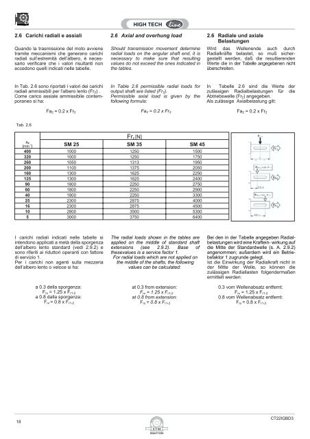
In Tab. 2.6 sono riportati i valori dei carichi<br />
radiali ammissibili per l’albero lento (Fr 2 ) .<br />
Come carico assiale ammissibile contemporaneo<br />
si ha:<br />
Fa 2 = 0.2 x Fr 2<br />
In Table 2.6 permissible radial loads for In Tabelle 2.6 sind die Werte der<br />
Fa 2 = 0.2 x Fr 2 Fa 2 = 0.2 x Fr 2<br />
output shaft are listed (Fr 2 ).<br />
zulässigen Radialbelastungen für die<br />
Permissible axial load is given by the<br />
following formula:<br />
Abtriebswelle (Fr 2 ) angegeben.<br />
Als zulässige Axialbelastung gilt:<br />
Tab. 2.6<br />
Fr 2 [N]<br />
n 2<br />
[min -1 ] <strong>SM</strong> <strong>25</strong> <strong>SM</strong> 35 <strong>SM</strong> 45<br />
400 1000 1<strong>25</strong>0 1500<br />
320 1000 1<strong>25</strong>0 1750<br />
260 1050 1313 1950<br />
200 1100 1375 2050<br />
160 1300 16<strong>25</strong> 2<strong>25</strong>0<br />
1<strong>25</strong> 1300 16<strong>25</strong> 2400<br />
90 1800 2<strong>25</strong>0 2750<br />
60 1800 2<strong>25</strong>0 2900<br />
40 1800 2<strong>25</strong>0 3300<br />
<strong>25</strong> 2300 2875 4000<br />
16 2300 2875 4500<br />
10 2800 3500 5300<br />
5 3000 3750 6400<br />
I carichi radiali indicati nelle tabelle si<br />
intendono applicati a metà della sporgenza<br />
dell’albero lento standard (vedi 2.9.2) e<br />
sono riferiti ai riduttori operanti con fattore<br />
di servizio 1.<br />
Per i carichi non agenti sulla mezzeria<br />
dell’albero lento o veloce si ha:<br />
a 0.3 della sporgenza:<br />
F rx = 1.<strong>25</strong> x F r1-2<br />
a 0.8 dalla sporgenza:<br />
F rx = 0.8 x F r1-2<br />
The radial loads shown in the tables are<br />
applied on the middle of standard shaft<br />
extensions (see 2.9.2). Base of<br />
thesevalues is a service factor 1.<br />
For radial loads which are not applied on<br />
the middle of the shafts, the following<br />
values can be calculated:<br />
at 0.3 from extension:<br />
F rx = 1.<strong>25</strong> x F r1-2<br />
at 0.8 from extension:<br />
F rx = 0.8 x F r1-2<br />
Bei den in der Tabelle angegeben Radialbelastungen<br />
wird eine Kraftein- wirkung auf<br />
die Mitte der Standardwelle (s. A. 2.9.2)<br />
angenommen; außerdem wird ein Betriebsfaktor<br />
1 zugrunde gelegt.<br />
Ist die Einwirkung der Radialkraft nicht in<br />
der Mitte der Welle, so können die<br />
zulässigen Radiallasten folgendermaßen<br />
ermittelt werden:<br />
0.3 vom Wellenabsatz entfernt:<br />
F rx = 1.<strong>25</strong> x F r1-2<br />
0.8 vom Wellenabsatz entfernt:<br />
F rx = 0.8 x F r1-2<br />
18<br />
CT22IGBD3