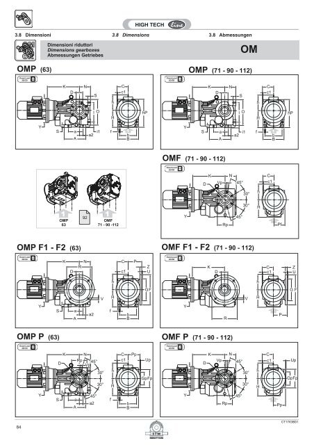
OMP F1 - F2 (63) OMP P (63) OMP (63) - Plastorgomma
OMP F1 - F2 (63) OMP P (63) OMP (63) - Plastorgomma
OMP F1 - F2 (63) OMP P (63) OMP (63) - Plastorgomma

You also want an ePaper? Increase the reach of your titles
YUMPU automatically turns print PDFs into web optimized ePapers that Google loves.
3.8 Dimensioni 3.8 Dimensions3.8 AbmessungenOR. a A a2 b B C c1DH7dj6f h H hP I i1 L m M N O Pf S<strong>63</strong> 110 147 28 100 120 60 2,5 (25)(28)3071 130 165 35 120 142 75 3 (30)(32)3590 120 182 30 140 170 90 3.5 (42)(45)40(48)112 150 215 40 165 200 105 4 50(55)16 11 100 100 170 115 32 40 M6 170 <strong>63</strong> 150 57.5 1416 11 108 112 183 130 37 40 M6 246 71 170 72 1819 14 129 140 232 160 45 40 M6 283 90 212 86.5 2224 17.5 151 180 294 200 55 50 M8 328 112 264 101 25OR.Gpg6Fp Pp Rp Up Vp F<strong>63</strong> 80 105 69 90 3 N°6 M6x1271 80 120 83 100 3 N°6 M8x15Gg6P R U V Z<strong>F1</strong> 160 11084130 3.5 N°4 9 10<strong>F2</strong> - - - - - -<strong>F1</strong> 200 130165 3.5 N°4 11 12100<strong>F2</strong> 160 110 130 3.5 N°4 9x5 1090 105 150 98.5 125 3.5 N°6 M12x18112 125 175 115 150 3.5 N°6 M14x18<strong>F1</strong> 250 180113215 4 N°4 13.5 15<strong>F2</strong> - - - - - -<strong>F1</strong> 300 230142265 4 N°4 13.5 16<strong>F2</strong> - - - - - -CT17IGBD1.189
YY3.8 Dimensioni 3.8 Dimensions3.8 AbmessungenDimensioni riduttoriDimensions gearboxesAbmessungen GetriebesROC3 - ROC4SZVp*(n° 7)aSXdBPpUpROC3_ECEH2Rp*SYmdHLNH1aDGp*LSNfaMEbBSZVp*(n° 7)aSXdBPpUpROC3_PAMH2SYHLRp*NH1aDGp*LSNfaKbBSZVp*(n° 7)aSXdBPpUpROC4_ECEH2Rp*SYdRHRmRNH1aDGp*LSNfaMRERbBSZVp*(n° 7)aSXdBPpUpROC4_PAMH2SYHRRp*NH1aDGp*LSNfaKRbB(*) La flangiatura è prevista solo sul latoillustrato nel disegno.90(*) Flanging is foreseen only on the sideshown in the drawing.(*) Die Flanschung ist nur auf der Seite, die inder Zeichnung gezeigt wird, vorgesehen.CT17IGBD1
ROC3 ir a b B d12514016018020010...30.624 (j6)D(H7)dB(H8)35.6...46 210 160 200 24 (j6) 60 30 45 18 225 385 180 218 M850.6...107.1 24 (j6) 45 M89.8...30.028 (j6)E f H1 H2 HL L m M N S SX SY SZ Gp(G6)4550M8M8Pp Rp uP Vp258 160 20 200 130 32 140 105 215 5 M1235.0...45.2 240 180 220 28 (j6) 70 34 50 20 250 430 210 242 M8 287.5 180 22 220 145 36 155 117.5 235 5 M1449.7...107.1 24 (j6) 50 M810...30.628 (j6)35.6...46 260 200 250 28 (j6) 80 38 50 22 280 480 220 274 M850.6...109.1 24 (j6) 50 M89.7...31.745 (k6)34.1...43.5 300 225 280 35 (k6) 90 45 80 24 315 540 247 302 M1050110M8M1052.4...123.6 35 (k6) 80 M1010.1...31.150 (k6)35.9...45.7 340 250 315 40 (k6) 100 50 110 27 355 605 280 340 M10110M1250...125.8 40 (k6) 110 M10311 200 25 250 160 40 170 132.5 265 5 M1<strong>63</strong>65 225 28 280 177 50 195 148.5 300 5 M18395 250 32 315 200 60 215 167.5 350 5 M20ROC3IEC B5125 140 160 180 200Y K Y K Y K Y K Y K80-90 200 357100-112 250 367 250 401.5 250 425132 300 387 300 421.5 300 445 300 415 300 443160-180 350 417 350 451.5 350 475 350 433 350 461200 400 417 400 451.5 400 475 400 433 400 461225 450 481.5 450 505 450 4<strong>63</strong> 450 491250-280 550 505 550 464 550 492ROC4 a b B dRD(H7)dB(H8)ER f H1 H2 HR L mR* MR N SX SY SZGp(G6)Pp Rp Up Vp125 210 160 200 16 (j6) 60 30 40 18 225 385 132 218 M6 518 160 200 130 32 140 105 215 5 M12140 240 180 220 19 (j6) 70 34 40 20 250 430 149 242 M6 595 180 220 145 36 155 117.5 235 5 M14160 260 200 250 19 (j6) 80 38 40 22 280 480 159 274 M6 618 200 250 160 40 170 132.5 265 5 M16180 300 250 280 32 (k6) 90 45 80 24 315 540 171 302 M8 487 225 280 177 50 195 148.5 300 5 M18200 340 250 315 32 (k6) 100 50 80 27 355 605 204 340 M8 515 250 315 200 60 215 167.5 350 5 M20* Profondità utile filetto / Threaded lenght / GewindetiefeROC4IEC B5125 140 160 180 200Y KR Y KR Y KR Y KR Y KR<strong>63</strong> 140 48971 160 489 160 561 160 58480-90 200 509 200 576 200 599 200 4<strong>63</strong>.5 200 490100-112 250 519 250 586 250 609 250 478.5 250 506.5132 300 610 300 <strong>63</strong>3 300 499.5 300 527.5160-180 350 529.5 350 557.5CT17IGBD191
PARTICOLARE CORPO IN VERSIONEFLANGIATAPer un fissaggio del riduttore si possonoutilizzare anche I 4 fori "t F " nel piano inferioredel corpo flangiato con interasse X e Z.Fig. 3.7DETAIL OF THE FLANGED GEARCASEFor the gearbox fixing also the 4 threads“t F ” in the lower part of the flangedgearcase with dimensions X and Z can beusedDETAIL DES GEHÄUSES MIT ABTRIE-BSFLANSCHAuch die vier Gewinde “t F ”, welche sich imunteren Teil des Gehäuses befinden (mitden Maßen X und Z), können zur Montagedes Getriebes verwendet werden.a 2Fa FtFb FtF<strong>OMP</strong>...ORP...OCP...(<strong>63</strong>)tFOMF...ORF...OCF...(71 - 90 - 112)Tab. 3.8OMOCt F b F a F a 2FOR<strong>63</strong> N°4 M10 x 15 60 117 8271 N°4 M10 x 15 70 140 10090 N°4 M12 x 20 88 152 110112 N°4 M16 x 24 102 170 122PARTICOLARE DEI FORI "t" NELLAFLANGIA PPer il fissaggio al riduttore con i fori "Vp"considerare la lunghezza delle vitiadeguate, e che la quota “yt” non è filettata(vedi disegno).Fig. 3.9DETAIL "t" OF THE FLANGE P HOLESWhen P-flange is used please consider thatthe threads "Vp" are in gearcase and thatdistance “yt” does not have a thread (seedrawing).DETAIL "t" OF THE FLANGE P HOLESBei Verwendung des P-Flansches ist zubeachten, daß sich die Gewinde imGetriebegehäuse befinden und daß Maß“yt” kein Gewinde besitzt. Details sieheZeichnung.<strong>OMP</strong>_PORP_POCP_POMF_PORF_POCF_P(<strong>63</strong>)(71 - 90 - 112)Vpxtytfissaggio utenteassembly customerBefestugung von benutzerTab. 3.10Vp xt yt<strong>63</strong> N°6 M6 12 11,571 N°6 M8 15 1190 N°6 M12 18 12112 N°6 M14 23 14N.B.xt = profondità della parte filettata, utile per ilfissaggio delle vitiNOTE.xt = thread length.HINWEIS.xt = Gewindetiefe92CT17IGBD1
ALBERI LENTIAlbero lento cavo e albero con calettatorePer l’utilizzazione corretta del riduttore e delcalettatore eseguire il dimensionamentodell’albero lento standard e dell’albero lentoper calettatore come indicato nelle seguentifigure. Per le prescrizioni di montaggio dell’albero sul calettatore vedere le indicazioniriportate nel capitolo 1, paragrafo 1.9.OUTPUT SHAFTOutput shaft and output shaft shrinkdiscBelow there are listed the internaldimensions of the output shaft with keywayand with shrink disc.To guarantee best performance werecommend for the shafts of the clients thedimensions also shown below. Formounting the shaft with shrink disc, pleasesee information in chapter 1, paragraph 1.9.ABTRIEBSWELLENAbtriebswelle mit passfedernut undAbtriebswelle mit schrumpfscheibeUnten sind die Abmessungen derAbtriebshohlwellen in Paßfederu.Schrumpfscheibenausführung aufgeführt.Für eine bestmögliche Leistung empfehlenwir für die Wellen der Kunden die ebenfallsaufgeführten Abmessungen.Hinweise zur Montage der Wellen mitSchrumpfscheibe s. Paragraph 1.9.Fig. 3.11Albero lento cavoOutput shaft with keywayAbtriebswelle mit passfedernutAlbero con calettatoreOutput shaft with shrink discAbtriebswelle mit schrumpfscheibeTab. 3.12OMOCORC<strong>63</strong> 6071 7590 90112 105DH730(25)(28)35(30)(32)40(42)(45)(48)50(55)Albero lento cavoOutput shaft with keywayAbtriebswelle mit passfedernutd1M1 M2 M3 Dd Cch<strong>63</strong>02528353032404245485055DH7Alberolento cavo con calettatoreOutput shaft with shrink discAbtriebswelle mit schrumpfscheibed1m1 m2 m3 m4 g Ggh615 15 20 38 85 30 30 40 25 45 30 72 430 15 35 43 100 35 35 40 25 45 30 80 435 20 40 55 120 40 40 50 30 55 35 90 <strong>63</strong>5 25 45 61 140 50 50 55 40 60 45 110 1CT17IGBD193
Albero lento cavoOutput shaft with keywayAbtriebswelle mit passfedernutFig. 3.13LuDIN 472Sr- 0.1- 0.2D H7D H7DpFeD- 0.1- 0.2VTELinguetta / KeyUNI 6604EEBBA1ATab. 3.14ROC3 - ROC4125 140 160 180 200A 236.5 269 302 332 379A1 218 242 274 302 340B 109 121 137 151 170D 60 70 80 90 100Dp 168 183 226 226 260E 50 56 <strong>63</strong> 70 80Lu 184 207.5 239.5 261 299Sr 15 15 15 18 18Fe M27 M27 M27 M30 M30VTE M20x60 M20x60 M20x60 M24x75 M24x7594CT17IGBD1
Albero lento cavo con calettatoreFig. 3.15Lu1Output shaft with shrink discAbtriebswelle mit schrumpfscheibeSr- 0.1- 0.2D1 H7D H7DeDubDpFeD- 0.1- 0.2s3Lubs2VTEm3n3m4Lt1LtTab. 3.16ROC3 - ROC4125 140 160 180 200Lt 302 334.5 375.5 405.5 452.5Lt1 279 313 352 397 436m3 32 35 40 45 50n3 177 198 222 252 276m4 70 80 90 100 110Lu1 254 286 324 364 402Dp 168 183 226 226 260Dub 145 155 170 215 215Lub 32.5 39 44 54 54s2 25 27 28 33 34D 60 70 80 90 100D1 65 75 85 95 110De 80 90 100 120 130Sr 15 15 15 18 18Fe M27 M27 M27 M30 M30VTE M20x60 M20x60 M20x60 M24x75 M24x75Perno macchina / Customer shaft / MaschinachseTab. 3.17ROC3 - ROC4125 140 160 180 200B 50 58 67 72 81C 3.5 4 4.5 5 5.5D 60 70 80 90 100D1 65 75 85 95 110E 28 30 32 35 40F 176 198 225 257 281Lu1 254 286 324 364 402M M20 M20 M20 M24 M24R 2 2.2 2.5 2.5 3D1 h8Fig. 3.18Lu1EFB0.8 3.2 0.8D a1115°RMCD h6CT17IGBD195
ALBERO LENTO SPORGENTETutti i riduttori sono forniti con albero lentocavo. A richiesta, possono essere forniti kitdi montaggio per alberi sporgenti comprensividi linguette, rondelle e viti di fissaggio.Le dimensioni delle linguette sono conformialle norme UNI 6604-69.SINGLE OUTPUT SHAFTSAll gearboxes are supplied with hollowoutput shaft. On request there are availablealso assembly kits including output shafts,keys, washers and assembly screws. Thedimensions of the keys are conform withUNI 6604-69.EINSEITIGE ABTRIEBSWELLENAlle Getriebe werden mit Abtriebshohlwellegeliefert. Auf Anfrage sind auch Montagekitsinklusive Abtriebswellen, Paßfedern,Unterlegscheiben und Montageschraubenerhältlich. Die Abmessungen der Paßfedernsind konform mit der UNI 6604-69.Fig. 3.24L 2Tab. 3.23OM - OC - OR L 2 BDg6m 2L 1 X<strong>63</strong> 60 1 30 M10 50 571 70 0 35 M10 60 590 80 1 40 M10 70 5112 100 1 50 M12 90 5m 2L 1Tab. 3.25 Fig. 3.26ROC3 - ROC4125 140 160 180 200A 3 294 332.5 379.5 421 479C 8 9.5 19.5 18.5 24D 60 70 80 90 100G 16 18 20 22.5 25L 160 180 200 220 250L 1 100 110 125 140 160L 2 110 125 140 160 180Lu 184 207.5 239.5 261 299m 2 M20 M20 M20 M24 M24X 5 7.5 7.5 10 10ALBERO LENTO BISPORGENTEDOUBLE OUTPUT SHAFTSHOHLWELLE MIT DOPPELTEM WELLENENDETab. 3.27L2Fig. 3.28OMOCORROCL 1 L 2<strong>63</strong> 50 6071 60 7090 70 80112 90 100125 100 110140 110 125160 125 140180 140 160200 160 180Albero integraleIntegral shaftIntegralwelleAlbero riportatoInserted shaftAnsatzwelleL1CT17IGBD197
DISPOSITIVO ANTIRITORNOTutti i riduttori ROC possono essere dotatidi dispositivo antiritorno. Nelle grandezze125, 140, 160 viene montato internamenteper cui non comporta modifiche alleconfigurazioni ECE e PAM.Nelle grandezze 180 e 200 esso vieneinstallato nella esecuzione PAM comeindicato negli schemi seguenti.Fig. 3.29ANTIRUN-BACK DEVICEAll ROC gearboxes may be fitted with theantirun-back device. In sizes 125, 140 and160 it is mounted on the inside therefore nomodifications are required in the ECE andPAM configurations.For sizes 180 and 200 it may be installedonly in PAM execution as shown in thediagrams below.ZdMUMKEHRSCHUTZVORRICHTUNGAlle Getriebe ROC können mit einerUmkehrschutzvorrichtung ausgestattetwerden. Bei den Baugrößen 125, 140 und160 wird diese Vorrichtung intern montiert,daher sind keine Änderungen an denKonfigurationen ECE und Pam erforderlich.Bei den Baugrößen 180 und 200 kanndiese Vorrichtung nur in der AusführungPAM installiert werden, wie in denfolgenden Schaltplänen angegeben.ZdMHRCMIMFM(G6)HLCMIMFM(G6)M2LMDM(H7)M3LMDM(H7)Tab. 3.30ROC 180ROC 200ROC3 - ROC4 ROC3 ROC4IEC DM LM CM Z IM FM dM n° M2 HR M3 HL100 28 60 180 5 215 250 14 4 —503.5112 28 60 180 5 215 250 14 4 — 503.5132 38 80 230 5 265 300 14 4 440 524.5160 42 110 250 6 300 350 18 4 458 554.5247180 48 110 250 6 300 350 18 4 468 —171200 55 110 300 6 350 400 18 4 473 —225 60 140 350 6 400 450 18 8 503 —250 65 140 450 6 500 550 18 8 514 —100 28 60 180 5 215 250 14 4 —531.5112 28 60 180 5 215 250 14 4 — 531.5132 38 80 230 5 265 300 14 4 468 552.5160 42 110 250 6 300 350 18 4 486 582.5280180 48 110 250 6 300 350 18 4 496 —204200 55 110 300 6 350 400 18 4 501 —225 60 140 350 6 400 450 18 8 531 —250 65 140 450 6 500 550 18 8 542 —FLANGIA USCITAOUTPUT FLANGEABTRIEBSFLANSCHTab. 3.31ROC FU CFU(G6)IFU dFU ZU SF LT125 350 250 300 18 6 18 177140 400 300 350 18 6 22 205160 450 350 400 18 6 25 230180 450 350 400 18 6 25 280200 550 450 500 18 6 25 280Fig. 3.32(125,140)(160..200)n°4 Dfu n°8 DfuLTCFUIFUFUZUSF98CT17IGBD1
3.11 Linguette3.11 Keys 3.11 PaßfedernAlbero entrataInput shaftAntriebswelleTab. 3.33d bxh t116 5x5 319 6x6 3.524 8x7 428 8X7 432 10X8 535 10X8 540 12X8 550 14X9 5.50/ +0.10/ +0.2Albero uscitaOutput shaftAbtriebswelleD bxh t225 8x7 3.328 8x7 3.330 8x7 3.332 10x8 3.335 10x8 3.340 12x8 3.342 12x8 3.345 14x9 3.848 14x9 3.850 14x9 3.855 16x10 4.360 18X11 4.470 20X12 4.980 22X14 5.490 25X14 5.4100 28X16 6.40/ +0.2CT17IGBD199
100CT17IGBD1
3.1 Caratteristiche tecnicheLa progettazione di questi riduttori è stataimpostata su una struttura monolitica particolarmenterigida che permette l’applicazione dielevati carichi.Carcasse e flange sono realizzate in ghisa meccanicaGG200 - GG250 ISO 185 ad eccezionedei tipi grandezza <strong>63</strong> e 71 realizzati in alluminioSG-AlSi UNI 1706.La lavorazione di tutte le carcasse avviene sumoderni centri di lavoro a controllo numerico chepermette di ottenere la massima precisionecostruttiva.L’albero di entrata è realizzato in acciaio39NiCrMo3 UNI EN 10083 bonificato; quello inuscita in acciaio C40 UNI 5332. Tutti gliingranaggi sono realizzati in acciaio 18NiCrMo5UNI 7846 cementati, temprati e rettificati permigliorarne il rendimento e la silenziosità anchesotto carico.3.1 Technical characteristicsThe design of this series of gearboxes has beenset up on a very rigid monolithic structureenabling the application of heavy loads.Housings and flanges are manufactured inengineering cast iron GG200 - GG250 ISO 185,except for size <strong>63</strong> and 71, made of aluminiumSG-AlSi UNI 1706.All the housings working takes place in numericalcontrol working centres, that ensure themaximum constructive accuracy.The input shaft is made spring tempered steel39NiCrMo3 UNI EN 10083; the output shaft ismade of steel C40 UNI 5332. All gears are madeof steel 18NiCrMo5 UNI 7846, previouslycasehardened, hardened and rectified toimprove efficiency and quietness even underload.3.1 Technische EigenschaftenDer Entwicklung dieser Getriebeserie wurde einemonolithische Gehäusestruktur zugrundegelegt.Mit Ausnahme der Modelle <strong>63</strong> und 71, bei denenaufgrund der kleinen Baugröße Aluminium SG-AISi UNI 1706 verwendet wird, sind alle Gehäuseund Flansche aus Maschinenguß GG200 -GG250 ISO 185.Die Bearbeitung der Gehäuse erfolgt aufmodernsten, numerisch gesteuerten Fertigungsmaschinen,wodurch eine hohe Fertigungsgenauigkeitund-qualität erzielt wird. DieAntriebswelle besteht aus einsatzgehärtetem undvergütetem 39NiCrMo3 Stahl UNI EN 10083, dieAbtriebswelle aus C40 Stahl UNI 5332. AlleZahnräder sind aus 18NiCrMo5 Stahl UNI 7846,gehärtet, einsatzgehärtet und geschliffen.Dies ermöglicht einen hohen Wirkung-sgradsowie einen geräuscharmen Lauf auch unter Last.Alle Kegelradgetriebe und-Getriebemotorenbesitzen drei Unterse- tzungsstufen.3.2 Designazione 3.2 Designation3.2 BezeichnungDesignazione riduttoriGearboxes designationBezeichnung GetriebesOM - OR - OCVersioneVersionAusführungGrand.SizeGrößeTipoTypeTyp* 1 * 2 * 3 *4 *5 ir IECTipoTypeTypGrandezzaSizeGrößeLunghezzaLenghtLängeDesignazione MotoriDesignation MotorsBezeichnung Motoren13180 (B5)80 (B14)....Esempio / ExampleBeispiel<strong>OMP</strong> 71 C 1:37.080 B5OMORSieheLeistungstabellenP**<strong>63</strong>-71-90-112F71-90-112<strong>63</strong>7190112—<strong>F1</strong><strong>F2</strong>P—S—BCDiametroforoopzionaleOptionalhollow shaftdiameterOptionalerHohlwellendurchmesser—SOAVeditabelleprestazioniSeeperformancetablesTTA....H56....315A....ML<strong>OMP</strong> 90 1: 92.3T 56 A 4 B5ORP <strong>63</strong> P SC1:27.4OC59 59TTA....H56....315A....MLOCP 112 C 1:57.1T 56 A 4** La versione P può montare le flange <strong>F1</strong>, <strong>F2</strong>, P solonella grandezza <strong>63</strong>** Version P may be fitted with flanges <strong>F1</strong>, <strong>F2</strong> and P onlyis size <strong>63</strong>.** Auf der Version P können die Flansche <strong>F1</strong>, <strong>F2</strong>, P nurin der Baugröße <strong>63</strong> montiert werden.Specifiche: Specification: Spezifikationen:]• [*1] Lato flangia uscita:Nessuna indicazione = flangia uscita conmontaggio destro (flange dal lato comeindicato nelle figure del catalogo);S = flange uscita con montaggio sinistro(flange dal lato opposto alle figureindicate a catalogo).• [*1] Mounting position output side:No indication (standard) = output flangeon right side (like indicated in the figures);S = output flange on left side (flanges onthe opposite side like indicated infigures).• [*1] Montageseite Abtriebsflansch:Keine Angabe (Standard) = Abtriebsflanschrechts (wie in den Abbildungendargestellt)S = Abtriebsflansch links (gegenüber derPosition in den Katalogabbildungen).56CT17IGBD1
• [*2] Albero uscita:Nessuna indicazione = albero forato;B = albero bisporgente integraleC = albero forato con calettatore.• [*3] Diametro albero:Nessuna indicazione = diametro forostandard dell’albero forato o forato concalettatore o bisporgente integrale;diametro oro opzionale = (vedi tabella3.1).• [*2] Output shaft:No indication = shaft with keyway;B = Double integral output shaftC = hollow shaft with shrink disk.• [*3] Shaft diameter:(for keyway and shrink disc connection)No indication = standard diameteroptional diameters = see table 3.1• [*2] Abtriebswelle:Keine Angabe = Hohlwelle mit PaßfedernutB = Doppeltem IntegralwelleC = Hohlwelle mit Schrumpfscheibe.• [*3] Durchmesser Abtriebswelle:(gültig für Paßfeder-und Schrumpfscheiben-Verbindung):Keine Angabe = StandarddurchmesserOptionale Durchmesser = s. Tabelle3.1Tab. 3.1GrandezzaSizeGrößeAlbero foratoShaft with keywayHolwelle mit Paßfedernut[*3]Albero forato con calettatoreHollow shaft with shrink discHolwelle mit SchrupmfscheibeBisporgente integraleDouble output shaftHolwelle mit Doppeltem WellenendeStandard Optional Standard Optional Standard Optional<strong>63</strong> 30 25 28 30 NO 30 NO71 35 30 32 35 NO 35 NO90 40 42 45 48 40 NO 40 NO112 50 55 50 NO 50 NO• [*4] Posizione calettatore (valido solamenteper soluzione con calettatore):Nessuna indicazione = lato destro comeindicato in Tab. 3.11 (standard);S = lato sinistro, montaggio dalla parteopposta alla Tab. 3.11 (opzionale).• [*5] Senso di rotazione (valido solo serichiesto dispositivo antiretro):O = ORARIO (il riduttore può ruotare soloin senso orario visto dal lato destro comein figura);A = ANTIORARIO.• [*4] Mounting position of shrink disc:No indication (standard) = on right side,as showed in Tab. 3.11;S = on left side, on the opposite likeindicated in Tab. 3.11.• [*5] Rotation sense (only necessaryfor solution with backstop device):O = CLOCKWISE (looking at the gearboxfrom the perspective shown below).A = ANTICLOCKWISE.• [*4] Montageposition Schrumpscheibe:Keine Angabe (Standard) = rechts (wiedargestellt in der Abbildung 3.11);S =links (gegenüber der Position in derAbbildung 3.11).• [*5] Drehrichtung (Nur bei Aus ührungenmit Rücklausperre):O = im Uhrzeigersinn (bei Betrachtungdes Getriebes aus der unten dargestelltenPerspektive);A = Gegen den Uhrzeigersinn.Altre specifiche: Further specification: Weitere Spezifikationen:• [M2, M3, M4, M5, M6] Posizioni dimontaggio con indicazione dei tappi dilivello, carico e scarico; se nonspecificato si considera standard laposizione M1 (vedi par. 3.4).• [T] Braccio di reazione.Braccio di reazione (vedi par. 3.9).• [2, 3, 4] Posizione della morsettiera delmotore se diversa da quella standard (1).• [M2, M3, M4, M5, M6] Mounting positionwith indication of breatherm level anddrain plugs; if not specified, standardposition is M1 (see par. 3.4).• [T] Torque arm(see pa. 3.9).• [2, 3, 4] Position of the motor terminalbox if different from the standard one (1).• Montageposition [M2, M3, M4, M5, M6]mit Angabe von . Entlüftung, Schaugläsernund Ablaßschraube. Wenn nicht näherspezifiziert, wird die Standard -position M1 zugrunde gelegt (s. Abschnitt3.4).• [T] Drehmomentstütze(s. Abschnitt 3.9)• Montageposition Klemmenkasten [2, 3, 4],wenn abweichend von Standardposition[1] (für Motorgetriebe).CT17IGBD157
Designazione riduttoriGearboxes designationBezeichnung GetriebesROCStadiStagesStüfigGrand.SizeGröße*6 irEntrataInputAntriebTipoTypeTypGrandezzaSizeGröße*7 *8Pos. montag.Mount. pos.EinbaulageDesignazione MotoriDesignation MotorsBezeichnung Motoren131Esempio / Example BeispielROCMROC34125140160180200DASAVeditabelleprestazioniSeeperformancetablesSieheLeistungstabellenPAM71...280ECET...H56....315ARNARBCCACBUAUBM1M2M3M4M5ROC 125 DA 10 ECE C M1ROC 125 DA 10 <strong>63</strong> C M1UD M61,2,3,4 MROC 125 DA 28 T 132MB 4-3 C M1Specifiche:• [*6] Senso di rotazione alberi:Si riferisce ai sensi di rotazione degli alberisecondo la schematizzazione sotto riportata.Specifications:• [*6] Shaft turning direction:This refers to the direction in which the shaftsturn according to the diagram below.ROC 3. ROC 4.Spezifikationen:• [*6] Drehrichtung Wellen:bezieht sich auf die jeweilige Drehrichtung derWellen entsprechend der nachfolgendaufgeführten schematischen Darstellung.DA• [*7] Senso di rotazione libero (valido solo serichiesto il dispositivo antiretro (interno per legrandezze 125, 140, 160 ed esterno, fornito aparte, per le grandezze 180 e 200) :ARN = Orario (l'albero uscita del riduttore puòruotare solo in senso orario, visto dal latosinistro come in figura).ARB = Antiorario (può ruotare solo in sensoantiorario)SADA• [*7] Free turning direction direction(applicable only if the antirun-back device isrequired (internal for sizes 125, 140, 160 andexternal, supplied separately, for sizes 180and 200) :ARN = Clockwise (the gearbox’s output shaftmay turn clockwise only, seen from theleft-hand side as in the figure).ARB = Counterclockwise (may turn counterclockwiseonly)SA• [*7] Freie Drehrichtung (lediglich dann gültig,wenn die interne Umkehrschutzvorrichtungangefordert wird, für die Baugrößen 125, 140und 160, sowie als externe Einrichtung mitseparater Lieferung für die Baugrößen 180und 200):ARN = Uhrzeigersinn (die Abtriebswelle desGetriebes kann sich ausschließlich imUhrzeigersinn drehen, ausgehend von der linkenSeite, gemäß Abbildung).ARB = Gegenuhrzeigersinn (die Abtriebswelledes Getriebes kann sich ausschließlichim Gegenuhrzeigersinn drehen).ARN (125 - 140 - 160) (125 - 140 - 160 - 180 - 200)• [*8] Albero uscitaC= albero cavo passante con cava linguettaCA= Albero cavo con calettatore montato asinistraCB= Albero cavo con calettatoremontato a destra• [*8] Output shaftC= hollow through shaft with keywaysCA= hollow shaft with shrink disk mountedon the left-hand sideCB= hollow shaft with shrink disk• [*8] AbtriebswelleC= Durchgangshohlwelle mit hohler PassfederCA= Hohlwelle mit links montierter KeilvorrichtungCB= Hohlwelle mit KeilvorrichtungUA UB UD• Altre specifiche— Braccio di reazione— Albero lento ad una sporgenza ebisporgente— Flangia uscita (applicabile solo sul latosinistro)58• Other specifications— Torque arm— Single and double output shaft— Output flange (may be mounted onleft-hand side only)• Sonstige Spezifikationen— Reaktionsarm— Hohlwelle mit einem Wellenende oderdoppeltem Wellenende— Abtriebsflansch (nur auf linker Seiteanwendbar)CT17IGBD1.1
3.3 Versioni3.3 Versions 3.3 AusührungenOM, OR, OC71 - 90 -112OM. (IEC)POM. (kW)OR.FF...FF...POC. <strong>63</strong>(OM - OR - OC)PP...FP...PSenso di rotazioneDirection of rotationDrehrichtungROC125 -140 - 160 - 180 - 200ROC PAM (IEC)MROC (kW)ROC3.ROC ECEROC4.Posizione morsettieraTerminal board positionLage des KlemmenkastensCT17IGBD159
3.4 Lubrificazione 3.4 Lubrication3.4 SchmierungLubrificazione riduttoriGearboxes lubricationSchmierung GetriebesOM - OR - OCGeneralitàSi consiglia l’uso di oli a base sintetica. (Vederea tale proposito le indicazioni riportate nelcapitolo 1, paragrafo 1.6).Nella Tab. 3.2 sono riportati i quantitativi di olionecessari per il corretto funzionamento deiriduttori.Prescrizioni in fase d’ordine e stato difornituraI riduttori della grandezza <strong>63</strong> è forniti completi diolio sintetico di viscosità ISO 320.Per questi riduttori non è necessario specificarela posizione di montaggio.I riduttori della grandezza 71 è forniti completi diolio sintetico di viscosità ISO 320.Per questi riduttori è necessario specificare laposizione di montaggio.I riduttori nelle grandezze 90, 112 sono fornitipredisposti per lubrificazione ad olio ma privi dilubrificante il quale potrà essere fornito arichiesta.Per questi riduttori è necessario specificare laposizione di montaggio.Posizioni di montaggioGeneral informationThe use of synthetic oil is recommended (seedetails in Chapter 1, paragraph 1.6).Tab. 3.2 shows the quantities of oil required forcorrect parallel-shaft mounted gearboxperformance.Ordering phase requirements and state ofsupplySize <strong>63</strong> gearbox is supplied with ISO 320viscosity synthetic oil.It is not necessary to specify mounting positionof this gearbox.Size 71 gearbox is supplied with ISO 320viscosity synthetic oil.It is necessary to specify the mounting positionwith these gearboxes.Size 90 and 112 . parallel - shaft mountedgearboxes are supplied pre-arranged for oillubrication but without lubricant that can berequested separately.It is necessary to specify the mounting positionwith these gearboxes.Mounting positionsAllgemeinesDer Einsatz von synthetischem Öl wirdempfohlen. (Siehe diesbezüglich die Hinweiseim Kapitel 1, Abschnitt 1.6).In der Tab. 3.2 werden die erforderlichenÖlfüllmengen für einen störungsfreien Betriebder Getriebe aufgeführt.Vorgaben für die bestellung und denlieferzustandDie Getriebe in der Baugröße <strong>63</strong> wird komplettmit Synthetiköl mit einer Viskosität ISO 320 geliefert.Für dieses Getriebe muss die Einbaulage nichtangegeben werden.Die Getriebe in der Baugröße 71 wird komplettmit Synthetiköl mit einer Viskosität ISO 320 geliefert.Für diese Getriebe muss die Einbaulage verbindlichangegeben werden.Die Getriebe in den Baugrößen 90 und 112 sindbei der Lieferung für die Ölschmierung vorbereitet,enthalten jedoch kein Schmiermittel. Dieseskann auf Anfrage geliefert werden.Für diese Getriebe muss die Einbaulageverbindlich angegeben werden.MontagepositionenCarico / Breather plug / Einfüll-u. EntlüftungsschraubeLivello / Level plug / SchauglasScarico / Drain plug / AblaßschraubeTab. 3.2OMOR - OCM1M2M3Quantità di lubrificante / Lubricant Quantity / Schmiermittelmenge (kg)Posizioni di montaggio /Mounting Positions / MontagepositionenM1 M2 M3 M4 M5 M6<strong>63</strong> 1.350M4Stato di fornituraState of supplyLieferzustandRiduttori forniti completi di olio sinteticoGearboxes suplied with synthetic oilGetriebe werden mit synthetischem ÖlgeliefertM5* n°. tappi olio* No.of plugsAnzahlBetriebschraube1M6Pos. montaggioMounting positionMontagepositionNon necessariaNot necessaryNichterforderlich71 1.35 1.25 1.95 1.55 1.7 1 Necessaria90 2.4 2.4 3.3 2.3 2.7 Riduttori predisposti per lubrificazione ad olio7NecessaryGearboxes suplied ready for oil lubrication112 4.9 4.1 6.7 5.0 5.5 Getriebe sind für Ölschmierung vorgesehen7ErforderlichATTENZIONEWARNINGACHTUNGM1M4 M5134A) Se in fase d’ordine la posizione di montaggio èomessa, il riduttore verrà fornito con i tappipredisposti per la posizione M1.B) Durante il riempimento attenersi ai quantitativi poichéin alcuni casi il livello del lubrificante oltrepassa laspia di livello.C) Il tappo di sfiato è allegato solo nei riduttori chehanno più di un tappo olio.D) Eventuali forniture con predisposizioni tappi diverseda quella indicata in tabella, dovranno essereconcordate.E) Nei riduttori dove è necessario specificare laposizione di montaggio, la posizione richiesta èindicata nella targhetta del riduttore.60A) It is necessary to specify the mounting position whenordering. If the mounting position is not specified inthe ordering phase, the gearbox supplied will haveplugs pre-arranged for position M1.B) During filling keep to the required quantities advisedas in some cases the level of the lubricant exceedsthe level shown by the indicator.C) A breather plug is supplied only with gearboxes thathave more than one oil plug.D) The supply of gearboxes with different plugpre-arrangements has to be agreed with themanufacturer.E) The gearboxes that need a specific assemblingposition have the indication of it on the label of thegearbox.A) In der Auftragsphase muss die Einbaulage verbindlichangegeben werden. Sollte dies nicht erfolgen,wird das Getriebe mit Stopfen für die EinbaulageM1.B) Für die Auffüllung sind die angegebenen Mengen zubeachten, da in einigen Fällen der Füllstand desSchmiermittels das Füllstands-Kontrollfenster übersteigt.C) Der Entlüftungsstopfen ist lediglich bei den Getriebenvorhanden, die über mehr als einen Ölfüllstopfenverfügen.D) Lieferungen, die eine Auslegung hinsichtlich der Stopfenaufweisen, die von den Angaben in der Tabelleabweichen, müssen vorab vereinbart werden.E) In den Getrieben in dem man die Montage Positionangeben soll, findet man die angefragte Position aufdem Typenschild des Getriebes.CT17IGBD1.1
Lubrificazione riduttoriGearboxes lubricationSchmierROC 3. ROC 4.ROCM1M1M2M2M3M3M4M4M5M5M6M6Carico / Breather plug / Einfüll-u. EntlüftungsschraubeLivello / Level plug / SchauglasScarico / Drain plug / Ablaßschraube 134Tab. 3.3M1M4 M5Quantità di lubrificante / Lubricant Quantity / Schmiermittelmenge (kg)Posizioni di montaggio / Mounting Positions / MontagepositionenROCM1 M2 M3 M4 M5-M6125 3 4 6 3.5 4140 5 6.5 10 6 6.5160 7 9 14 8 9180 11 15 22 13 15200 15 22 30 17 22CT17IGBD1.1Quantità di lubrificante / Lubricant Quantity / Schmiermittelmenge (kg)Posizioni di montaggio / Mounting Positions / MontagepositionenROCM1 M2 M3 M4 M5-M6125 3.5 4.5 6.5 4.5 4.5140 6 7.5 11 7.5 7.5160 8 10 15 9.5 10180 12.5 16.5 23 15 16.5200 16.5 23.5 31 19 23.561
3.5 Carichi radiali e assiali 3.5 Axial and overhung load 3.5 Radiale und axialeBelastungenQuando la trasmissione del moto avvienetramite meccanismi che generano carichiradiali sull’estremità dell’albero, è necessarioverificare che i valori risultanti noneccedano quelli indicati nelle tabelle.Nella Tab. 3.4 sono riportati i valori dei carichiradiali ammissibili per l’albero veloce(Fr 1 ). Come carico assiale ammissibilecontemporaneo si ha:Fa 1 = 0.2 x Fr 1Should transmission movement determineradial loads on the angular shaft end, it isnecessary to make sure that resultingvalues do not exceed the ones indicated inthe tables.Fa 1 = 0.2 x Fr 1WirdRadialkräftegestelltWerteüberschreiten.InzulässigenAntriebswelleAxialbelastungdaswerden,die inTabelleWellenendebelastet, sodaß die resultierendender Tabelle angegebenen3.4 sind dieRadialbelastungen(Fr 1 ) angegeben.beträgt dann:Fa 1 = 0.2 x Fr 1auchmußWertedurchsicher-nichtderfür dieDieIn Table 3.4 permissible radial load for inputshaft are listed (Fr 1 ). Contemporarypermissible axial load is given by thefollowing formula:Tab. 3.4ORn 1[min -1 ]Fr 1 [N]OR .<strong>63</strong> 71 90 1122800 320 430 520 6001400 400 550 700 800900 450 600 800 920500 500 850 1100 1300ROCROC125140160180200n 1[min -1 ]Fr 1 [N]i 31.5 35.5 i 45 50 i 112 i>1121450 2000 3600 4000 5501000 2200 4000 4500 600750 2500 4500 5000 8501450 2800 5000 3600 9001000 3200 5500 4000 1100750 3600 <strong>63</strong>00 4500 14001450 2000 4500 3200 7001000 2200 5000 3600 800750 2500 5600 4000 11001450 4000 5600 <strong>63</strong>00 <strong>63</strong>001000 4500 <strong>63</strong>00 7100 <strong>63</strong>00750 5000 7100 8000 <strong>63</strong>001450 5000 7100 8000 71001000 5500 8000 9000 7100750 <strong>63</strong>00 9000 10000 7100In Tab. 3.5 sono riportati i valori dei carichiradiali ammissibili per l’albero lento (Fr 2 ) .Come carico assiale ammissibile contemporaneosi ha:Fa 2 = 0.2 x Fr 2In Table 3.5 permissible radial loads for In Tabelle 3.5 sind die Werte derFa 2 = 0.2 x Fr 2 Fa 2 = 0.2 x Fr 2output shaft are listed (Fr 2 ).zulässigen Radialbelastungen für diePermissible axial load is given by thefollowing formula:Abtriebswelle (Fr 2 ) angegeben.Als zulässige Axialbelastung gilt:62CT17IGBD1
ORROCTab. 3.5Fr 2 [N]n 2OM . - OR . - OC .[min -1 ]<strong>63</strong> 71 90 112400 1500 2900 9000 11000320 1750 3000 10000 11500260 1950 3300 10600 12000200 2050 3600 11400 12500160 2250 3700 12000 13200125 2400 4050 12500 1330090 2750 4400 13500 1500060 2900 4800 13500 1660040 3300 5300 13500 1750025 4000 6500 13500 1750016 4500 6500 13500 1750010 5300 6500 13500 175005 6400 6500 13500 17500Fr 2 [N]n 2ROC.[min -1 ]125 140 160 180 200320 11100 13500 17500 19400 25200250 12200 15500 19200 21100 27800200 13100 16500 20500 23300 29500160 14200 17500 22100 24800 32000112 15500 19000 23500 27000 35200<strong>63</strong> 19000 23000 27500 34200 4460036 19000 29000 34000 41000 53200
3.6 Prestazioni riduttori OR3.6 OR gearboxes performances 3.6 Leistungen der OR-GetriebeOR 90 44.0irn 1 = 2800 min -1 n 1 = 1400 min -1 n 1 = 900 min -1 n 1 = 500 min -1 IECn 2 T 2M P RD n 2 T 2M P RD n 2 T 2M P RD n 2 T 2M P RDmin -1 Nm kW % min -1 Nm kW % min -1 Nm kW % min -1 Nm kW %7.2 388 325 14.7 90 194 430 9.7 90 125 457 6.6 90 69 545 4.4 909.0 310 350 12.6 90 155 450 8.1 90 100 490 5.7 90 55 586 3.7 9010.1 276 357 11.5 90 138 500 8.0 90 89 550 5.7 90 49 600 3.4 9011.5 244 400 11.4 90 122 520 7.4 90 79 560 5.1 90 44 613 3.1 9013.0 215 406 10.2 90 108 540 6.8 90 69 570 4.6 90 38 613 2.7 9014.0 200 528 12.3 90 100 590 6.9 90 64 740 5.5 90 36 850 3.6 9015.7 178 570 11.8 90 89 720 7.5 90 57 780 5.2 90 32 950 3.5 9017.7 158 570 10.5 90 79 750 6.8 90 51 820 4.9 90 28 950 3.1 9020.1 139 610 9.9 90 70 790 6.4 90 45 870 4.6 90 25 950 2.8 9023.0 122 640 9.1 90 61 820 5.8 90 39 900 4.1 90 22 950 2.4 9025.7 109 700 8.9 90 55 900 5.8 90 35 980 4.0 90 19.5 1122 2.5 9028.8 97 740 8.4 90 49 910 5.2 90 31 1040 3.8 90 17.3 1122 2.3 9032.5 86 740 7.4 90 43 910 4.6 90 28 1040 3.4 90 15.4 1122 2.0 9036.9 76 740 6.5 90 38 910 4.0 90 24 1040 2.9 90 13.5 1122 1.8 9042.2 66 740 5.7 90 33 910 3.5 90 21 1040 2.5 90 11.9 1122 1.6 9045.2 62 740 5.3 90 31 910 3.3 90 19.9 1040 2.4 90 11.1 1122 1.4 9052.4 53 740 4.6 90 27 910 2.9 90 17.2 1040 2.1 90 9.5 1122 1.2 9059.5 47 740 4.0 90 24 910 2.5 90 15.1 1040 1.8 90 8.4 1122 1.1 9073.3 38 740 3.3 90 19.1 910 2.0 90 12.3 1040 1.5 90 6.8 1122 0.89 9080.7 35 740 3.0 90 17.4 910 1.8 90 11.2 1040 1.4 90 6.2 1122 0.81 9092.5 30 740 2.6 90 15.1 910 1.6 90 9.7 1040 1.2 90 5.4 1122 0.70 9094.4 30 740 2.6 90 14.8 910 1.6 90 9.5 1040 1.1 90 5.3 1122 0.69 90106.7 26 740 2.2 90 13.1 910 1.4 90 8.4 1040 1.0 90 4.7 1122 0.61 90122.3 23 740 2.0 90 11.4 910 1.2 90 7.4 1040 0.90 90 4.1 1122 0.54 90131.1 21 740 1.8 90 10.7 910 1.1 90 6.9 1040 0.83 90 3.8 1122 0.50 90151.9 18.4 740 1.6 90 9.2 910 0.97 90 5.9 1040 0.71 90 3.3 1122 0.43 90165.2 16.9 740 1.5 90 8.5 910 0.90 90 5.4 1040 0.65 90 3.0 1122 0.39 90212.6 13.2 740 1.1 90 6.6 910 0.70 90 4.2 1040 0.51 90 2.4 1122 0.31 90234.1 12.0 740 1.0 90 6.0 910 0.64 90 3.8 1040 0.46 90 2.1 1122 0.27 90268.3 10.4 740 0.90 90 5.2 910 0.55 90 3.4 1040 0.41 90 1.9 1122 0.25 90294.9 9.5 740 0.82 90 4.7 910 0.50 90 3.1 1040 0.38 90 1.7 1122 0.22 90309.6 9.0 740 0.77 90 4.5 910 0.48 90 2.9 1040 0.35 90 1.6 1122 0.21 90338.1 8.3 740 0.71 90 4.1 910 0.43 90 2.7 1040 0.33 90 1.5 1122 0.20 90390.0 7.2 740 0.62 90 3.6 910 0.38 90 2.3 1040 0.28 90 1.3 1122 0.17 90132 B5132 B14112 B5112 B14100 B5100 B1490 B590 B1480 B580 B1471 B5CT17IGBD165
3.6 Prestazioni riduttori OR3.6 OR gearboxes performances 3.6 Leistungen der OR-GetriebeOR 112 68.0irn 1 = 2800 min -1 n 1 = 1400 min -1 n 1 = 900 min -1 n 1 = 500 min -1 IECn 2 T 2M P RD n 2 T 2M P RD n 2 T 2M P RD n 2 T 2M P RDmin -1 Nm kW % min -1 Nm kW % min -1 Nm kW % min -1 Nm kW %7.7 366 540 23 90 183 670 14.3 90 118 760 10.4 90 65 800 6.1 908.9 315 580 21 90 157 715 13.1 90 101 810 9.5 90 56 850 5.5 9011.8 238 690 19.1 90 119 850 11.8 90 77 970 8.7 90 43 1000 5.0 9013.1 214 720 17.9 90 107 890 11.1 90 69 1000 8.0 90 38 1050 4.6 9016.1 174 940 19.0 90 87 1160 11.7 90 56 1300 8.5 90 31 1400 5.0 9017.9 156 1000 18.2 90 78 1230 11.2 90 50 1400 8.1 90 28 1450 4.7 9020.9 134 1040 16.2 90 67 1280 10.0 90 43 1460 7.3 90 24 1500 4.2 9022.3 126 1350 19.8 90 <strong>63</strong> 1750 12.8 90 40 1850 8.6 90 22 1900 4.9 9023.6 119 1100 15.2 90 59 1350 9.3 90 38 1540 6.8 90 21 1500 3.7 9025.6 109 1130 14.3 90 55 1400 9.0 90 35 1600 6.5 90 19.5 1600 3.6 9029.4 95 1420 15.7 90 48 1750 9.8 90 31 1900 6.9 90 17.0 1900 3.8 9032.8 85 1450 14.3 90 43 1750 8.8 90 27 1900 6.0 90 15.2 1900 3.4 9038.2 73 1450 12.3 90 37 1750 7.5 90 24 1900 5.3 90 13.1 1900 2.9 9043.2 65 1450 11.0 90 32 1750 6.5 90 21 1900 4.6 90 11.6 1900 2.6 9046.8 60 1450 10.1 90 30 1750 6.1 90 19.2 1900 4.2 90 10.7 1900 2.4 9053.4 52 1450 8.8 90 26 1750 5.3 90 16.9 1900 3.7 90 9.4 1900 2.1 9057.2 49 1450 8.3 90 24 1750 4.9 90 15.7 1900 3.5 90 8.7 1900 1.9 9064.6 43 1450 7.3 90 22 1750 4.5 90 13.9 1900 3.1 90 7.7 1900 1.7 9077.0 36 1450 6.1 90 18.2 1750 3.7 90 11.7 1900 2.6 90 6.5 1900 1.4 9085.4 33 1450 5.6 90 16.4 1750 3.3 90 10.5 1900 2.3 90 5.9 1900 1.3 9093.9 30 1450 5.1 90 14.9 1750 3.0 90 9.6 1900 2.1 90 5.3 1900 1.2 90102.8 27 1450 4.6 90 13.6 1750 2.8 90 8.8 1900 1.9 90 4.9 1900 1.1 90110.9 25 1450 4.2 90 12.6 1750 2.6 90 8.1 1900 1.8 90 4.5 1900 0.99 90125.2 22 1450 3.7 90 11.2 1750 2.3 90 7.2 1900 1.6 90 4.0 1900 0.88 90135.6 21 1450 3.5 90 10.3 1750 2.1 90 6.6 1900 1.5 90 3.7 1900 0.82 90154.8 18.1 1450 3.1 90 9.0 1750 1.8 90 5.8 1900 1.3 90 3.2 1900 0.71 90166.0 16.9 1450 2.9 90 8.4 1750 1.7 90 5.4 1900 1.2 90 3.0 1900 0.66 90194.9 14.4 1450 2.4 90 7.2 1750 1.5 90 4.6 1750 0.94 90 2.6 1750 0.53 90223.5 12.5 1450 2.1 90 6.3 1750 1.3 90 4.0 1900 0.88 90 2.2 1900 0.49 90247.9 11.3 1450 1.9 90 5.6 1750 1.1 90 3.6 1900 0.80 90 2.0 1900 0.44 90272.4 10.3 1450 1.7 90 5.1 1750 1.0 90 3.3 1900 0.73 90 1.8 1900 0.40 90298.1 9.4 1450 1.6 90 4.7 1750 0.96 90 3.0 1900 0.66 90 1.7 1900 0.38 90342.9 8.2 1450 1.4 90 4.1 1750 0.83 90 2.6 1750 0.53 90 1.5 1750 0.31 90375.3 7.5 1450 1.3 90 3.7 1750 0.75 90 2.4 1750 0.49 90 1.3 1750 0.26 90160 B5132 B5112 B5100 B590 B580 B5N.B. Per i riduttori evidenziati dal doppiobordo nella colonna delle potenze ènecessario verificare lo scambio termicodel riduttore (come indicato nel par. 1.5).Per maggiori informazioni contattarel’ufficio tecnico STM.N.B.I pesi riportati sono indicativi e possonovariare in funzione della versione delriduttore.NOTE. Please pay attention to the framearound the input power value: for thisgearboxes it’s important to check thethermal capacity (comp. par. 1.5). Fordetails please contact our technicaldepartment).For details please contact our technicalNOTE.Listed weights are for reference only andcan vary according to the gearbox version.HINWEIS. Sind in den TabellenNennleistungen eingerahmt, so ist diethermische Leistungsgrenze der Getriebezu beachten (s. Kapitel 1.5).Für weitere Informationen wenden Sie sichbitte and unser technisches Büro.HINWEIS.Die angegeben Gewichtsmaße sindRichtwerte und können je nachGetriebeversion variieren.66CT17IGBD1
3.6 Prestazioni riduttori ROCROC 1253.6 ROC gearboxes performances 3.6 Leistungen der ROC-Getriebe100irn 1 = 2800 min -1 n 1 = 1400 min -1 n 1 = 900 min -1 n 1 = 500 min -1 IECn 2 T 2M P RD n 2 T 2M P RD n 2 T 2M P RD n 2 T 2M P RDmin -1 Nm kW % min -1 Nm kW % min -1 Nm kW % min -1 Nm kW %ROC3.10.0 280 2140 67 94 145 2250 36 94 90 2500 25 94 50 2600 14.5 9412.4 226 2380 60 94 117 2500 33 94 73 2550 21 94 40 2650 11.9 9416.3 172 2380 46 94 89 2500 25 94 55 2550 15.7 94 31 2650 9.1 9420.6 136 2420 37 94 70 2550 20 94 44 2600 12.7 94 24 2750 7.4 9423.3 120 2470 33 94 62 2600 18.0 94 39 2650 11.4 94 21 2750 6.6 9424.9 113 2470 31 94 58 2600 16.9 94 36 2650 10.7 94 20 2800 6.3 9428.5 98 2470 27 94 51 2600 14.7 94 32 2650 9.3 94 17.6 2800 5.5 9430.6 92 2470 25 94 47 2600 13.7 94 29 2650 8.7 94 16.3 2800 5.1 9435.6 79 2570 23 94 41 2700 12.2 94 25 2750 7.7 94 14.0 2800 4.4 9438.6 73 2570 21 94 38 2700 11.3 94 23 2750 7.1 94 13.0 2800 4.0 9446.0 61 2570 17.4 94 32 2700 9.5 94 19.6 2750 6.0 94 10.9 2800 3.4 9450.6 55 2660 16.4 94 29 2800 8.9 94 17.8 2800 5.5 94 9.9 2800 3.1 9455.1 51 2660 15.1 94 26 2800 8.2 94 16.3 2800 5.1 94 9.1 2800 2.8 9465.0 43 2660 12.8 94 22 2800 7.0 94 13.8 2800 4.3 94 7.7 2800 2.4 9471.2 39 2660 11.7 94 20 2800 6.4 94 12.6 2800 3.9 94 7.0 2800 2.2 9482.9 34 2570 9.7 94 17.5 2700 5.3 94 10.9 2750 3.3 94 6.0 2800 1.9 9489.8 31 2570 8.9 94 16.1 2700 4.9 94 10.0 2750 3.1 94 5.6 2800 1.7 9497.8 29 2570 8.2 94 14.8 2700 4.5 94 9.2 2750 2.8 94 5.1 2800 1.6 94107.1 26 2570 7.5 94 13.5 2700 4.1 94 8.4 2750 2.6 94 4.7 2800 1.5 94ROC4.126.8 22 2660 6.7 92 11.4 2800 3.6 92 7.1 2800 2.3 92 3.9 2800 1.3 92137.5 20 2660 6.2 92 10.5 2800 3.4 92 6.5 2800 2.1 92 3.6 2800 1.2 921<strong>63</strong>.9 17.1 2660 5.2 92 8.8 2800 2.8 92 5.5 2800 1.7 92 3.1 2800 1.0 92180.4 15.5 2660 4.7 92 8.0 2800 2.6 92 5.0 2800 1.6 92 2.8 2800 0.9 92207.0 13.5 2570 4.0 92 7.0 2700 2.2 92 4.3 2750 1.4 92 2.4 2800 0.8 92225.4 12.4 2570 3.6 92 6.4 2700 2.0 92 4.0 2750 1.2 92 2.2 2800 0.7 92246.6 11.4 2570 3.3 92 5.9 2700 1.8 92 3.6 2750 1.1 92 2.0 2800 0.6 92271.4 10.3 2570 3.0 92 5.3 2700 1.6 92 3.3 2750 1.0 92 1.8 2800 0.6 92303.0 9.2 2570 2.7 92 4.8 2700 1.5 92 3.0 2750 0.9 92 1.6 2800 0.5 92352.7 7.9 2570 2.3 92 4.1 2700 1.3 92 2.6 2750 0.8 92 1.4 2800 0.5 92382.5 7.3 2570 2.1 92 3.8 2700 1.2 92 2.4 2750 0.7 92 1.3 2800 0.4 92455.8 6.1 2570 1.8 92 3.2 2700 1.0 92 2.0 2750 0.6 92 1.1 2800 0.3 92501.6 5.6 2570 1.6 92 2.9 2700 0.9 92 1.8 2750 0.6 92 1.0 2800 0.3 92555.7 5.0 2570 1.5 92 2.6 2700 0.8 92 1.6 2750 0.5 92 0.9 2800 0.3 9290 B5100 B5112 B5132 B5160 B5180 B5200 B5110<strong>63</strong> B571 B580 B590 B5100 B5112 B5CT17IGBD167
3.6 Prestazioni riduttori ROCROC 1403.6 ROC gearboxes performances 3.6 Leistungen der ROC-Getriebe140irn 1 = 2800 min -1 n 1 = 1400 min -1 n 1 = 900 min -1 n 1 = 500 min -1 IECn 2 T 2M P RD n 2 T 2M P RD n 2 T 2M P RD n 2 T 2M P RDmin -1 Nm kW % min -1 Nm kW % min -1 Nm kW % min -1 Nm kW %ROC3.9.8 285 3090 98 94 148 3250 53 94 92 3500 36 94 51 3700 21 9412.1 231 3280 84 94 119 3450 46 94 74 3600 30 94 41 3800 17.4 9416.0 175 3330 65 94 91 3500 35 94 56 3600 23 94 31 3800 13.2 9420.2 139 3420 53 94 72 3600 29 94 45 3700 18.4 94 25 3900 10.8 9422.9 122 3520 48 94 <strong>63</strong> 3700 26 94 39 3800 16.7 94 22 3900 9.5 9424.4 115 3520 45 94 59 3700 24 94 37 3800 15.6 94 20 4000 9.1 9428.0 100 3520 39 94 52 3700 21 94 32 3800 13.6 94 17.9 4000 8.0 9430.0 93 3520 37 94 48 3700 19.9 94 30 3800 12.7 94 16.6 4000 7.4 9435.0 80 3610 32 94 41 3800 17.6 94 26 3900 11.2 94 14.3 4000 6.4 9437.9 74 3610 30 94 38 3800 16.2 94 24 3900 10.3 94 13.2 4000 5.9 9445.2 62 3610 25 94 32 3800 13.6 94 19.9 3900 8.7 94 11.1 4000 4.9 9449.7 56 3800 24 94 29 4000 13.0 94 18.1 4000 8.1 94 10.1 4000 4.5 9453.9 52 3800 22 94 27 4000 12.0 94 16.7 4000 7.4 94 9.3 4000 4.1 9464.5 43 3800 18.4 94 22 4000 10.0 94 14.0 4000 6.2 94 7.8 4000 3.5 9471.2 39 3800 16.7 94 20 4000 9.1 94 12.6 4000 5.6 94 7.0 4000 3.1 9481.2 35 3610 13.9 94 17.9 3800 7.6 94 11.1 3900 4.8 94 6.2 4000 2.7 9488.5 32 3610 12.7 94 16.4 3800 6.9 94 10.2 3900 4.4 94 5.7 4000 2.5 9497.0 29 3610 11.6 94 14.9 3800 6.3 94 9.3 3900 4.0 94 5.2 4000 2.3 94107.1 26 3610 10.5 94 13.5 3800 5.7 94 8.4 3900 3.7 94 4.7 4000 2.1 94ROC4.126.7 22 3800 9.6 92 11.4 4000 5.2 92 7.1 4000 3.2 92 3.9 4000 1.8 92137.4 20 3800 8.8 92 10.6 4000 4.8 92 6.5 4000 3.0 92 3.6 4000 1.7 921<strong>63</strong>.8 17.1 3800 7.4 92 8.9 4000 4.0 92 5.5 4000 2.5 92 3.1 4000 1.4 92180.2 15.5 3800 6.7 92 8.0 4000 3.7 92 5.0 4000 2.3 92 2.8 4000 1.3 92206.8 13.5 3800 5.9 92 7.0 3800 3.0 92 4.4 3900 1.9 92 2.4 4000 1.1 92225.2 12.4 3610 5.1 92 6.4 3800 2.8 92 4.0 3900 1.8 92 2.2 4000 1.0 92246.4 11.4 3610 4.7 92 5.9 3800 2.5 92 3.7 3900 1.6 92 2.0 4000 0.9 92271.2 10.3 3610 4.2 92 5.3 3800 2.3 92 3.3 3900 1.5 92 1.8 4000 0.8 92308.8 9.1 3610 3.7 92 4.7 3800 2.0 92 2.9 3900 1.3 92 1.6 4000 0.7 92359.4 7.8 3610 3.2 92 4.0 3800 1.7 92 2.5 3900 1.1 92 1.4 4000 0.6 92389.8 7.2 3610 3.0 92 3.7 3800 1.6 92 2.3 3900 1.0 92 1.3 4000 0.6 92424.5 6.6 3610 2.7 92 3.4 3800 1.5 92 2.1 3900 0.9 92 1.2 4000 0.5 92511.2 5.5 3610 2.3 92 2.8 3800 1.2 92 1.8 3900 0.8 92 1.0 4000 0.4 92566.4 4.9 3610 2.0 92 2.6 3800 1.1 92 1.6 3900 0.7 92 0.9 4000 0.4 92100 B5112 B5132 B5160 B5180 B5200 B5225 B515571 B580 B590 B5100 B5112 B5132 B568CT17IGBD1
3.6 Prestazioni riduttori ROCROC 1603.6 ROC gearboxes performances 3.6 Leistungen der ROC-Getriebe180irn 1 = 2800 min -1 n 1 = 1400 min -1 n 1 = 900 min -1 n 1 = 500 min -1 IECn 2 T 2M P RD n 2 T 2M P RD n 2 T 2M P RD n 2 T 2M P RDmin -1 Nm kW % min -1 Nm kW % min -1 Nm kW % min -1 Nm kW %ROC3.10.0 280 4660 145 94 145 4900 79.1 94 90 5000 50 94 50 5200 29 9412.4 226 4750 120 94 117 5000 65.3 94 73 5100 41 94 40 5300 24 9416.3 172 4750 91 94 89 5000 49.6 94 55 5100 31 94 31 5300 18.1 9420.6 136 4850 74 94 70 5100 40.0 94 44 5200 25 94 24 5500 14.9 9423.3 120 4940 66 94 62 5200 36.0 94 39 5300 23 94 21 5500 13.1 9424.9 113 4940 62 94 58 5200 33.8 94 36 5300 21 94 20 5600 12.5 9428.5 98 4940 54 94 51 5200 29.5 94 32 5300 18.7 94 17.6 5600 11.0 9430.6 92 4940 50 94 47 5200 27.5 94 29 5300 17.4 94 16.3 5600 10.2 9435.6 79 5130 45 94 41 5400 24.5 94 25 5500 15.5 94 14.0 5600 8.8 9438.6 73 5130 41 94 38 5400 22.6 94 23 5500 14.3 94 13.0 5600 8.1 9446.0 61 5130 35 94 32 5400 19.0 94 19.6 5500 12.0 94 10.9 5600 6.8 9450.6 55 5320 33 94 29 5600 17.9 94 17.8 5600 11.1 94 9.9 5600 6.2 9454.9 51 5320 30 94 26 5600 16.5 94 16.4 5600 10.2 94 9.1 5600 5.7 9465.7 43 5320 25 94 22 5600 13.8 94 13.7 5600 8.5 94 7.6 5600 4.7 9472.5 39 5320 23 94 20 5600 12.5 94 12.4 5600 7.7 94 6.9 5600 4.3 9482.7 34 5130 19.4 94 17.5 5400 10.6 94 10.9 5500 6.7 94 6.0 5600 3.8 9490.1 31 5130 17.8 94 16.1 5400 9.7 94 10.0 5500 6.1 94 5.5 5600 3.5 9498.8 28 5130 16.2 94 14.7 5400 8.8 94 9.1 5500 5.6 94 5.1 5600 3.2 94109.1 26 5130 14.7 94 13.3 5400 8.0 94 8.3 5500 5.1 94 4.6 5600 2.9 94ROC4.129.1 22 5320 13.1 92 11.2 5600 7.2 92 7.0 5600 4.4 92 3.9 5600 2.5 92140.0 20 5320 12.1 92 10.4 5600 6.6 92 6.4 5600 4.1 92 3.6 5600 2.3 92166.8 16.8 5320 10.2 92 8.7 5600 5.5 92 5.4 5600 3.4 92 3.0 5600 1.9 92183.6 15.3 5320 9.2 92 7.9 5600 5.0 92 4.9 5600 3.1 92 2.7 5600 1.7 92210.6 13.3 5130 7.8 92 6.9 5400 4.2 92 4.3 5500 2.7 92 2.4 5600 1.5 92229.3 12.2 5130 7.1 92 6.3 5400 3.9 92 3.9 5500 2.5 92 2.2 5600 1.4 92251.0 11.2 5130 6.5 92 5.8 5400 3.6 92 3.6 5500 2.2 92 2.0 5600 1.3 92276.2 10.1 5130 5.9 92 5.3 5400 3.2 92 3.3 5500 2.0 92 1.8 5600 1.2 92314.6 8.9 5130 5.2 92 4.6 5400 2.8 92 2.9 5500 1.8 92 1.6 5600 1.0 92366.1 7.6 5130 4.5 92 4.0 5400 2.4 92 2.5 5500 1.5 92 1.4 5600 0.9 92397.0 7.1 5130 4.1 92 3.7 5400 2.2 92 2.3 5500 1.4 92 1.3 5600 0.8 92432.3 6.5 5130 3.8 92 3.4 5400 2.1 92 2.1 5500 1.3 92 1.2 5600 0.7 92520.6 5.4 5130 3.1 92 2.8 5400 1.7 92 1.7 5500 1.1 92 1.0 5600 0.6 92576.8 4.9 5130 2.8 92 2.5 5400 1.5 92 1.6 5500 1.0 92 0.9 5600 0.6 92100 B5112 B5132 B5160 B5180 B5200 B5225 B5250 B520071 B580 B590 B5100 B5112 B5132 B5CT17IGBD169
3.6 Prestazioni riduttori ROC3.6 ROC gearboxes performances 3.6 Leistungen der ROC-GetriebeROC 180 270irn 1 = 2800 min -1 n 1 = 1400 min -1 n 1 = 900 min -1 n 1 = 500 min -1 IECn 2 T 2M P RD n 2 T 2M P RD n 2 T 2M P RD n 2 T 2M P RDmin -1 Nm kW % min -1 Nm kW % min -1 Nm kW % min -1 Nm kW %ROC3.9.7 290 6180 199 94 150 6500 109 94 93 7050 73 94 52 7500 43 9412.9 217 6650 161 94 113 7000 88 94 70 7150 56 94 39 7700 33 9416.0 175 6650 130 94 91 7000 71 94 56 7150 45 94 31 7700 27 9420.1 139 6840 106 94 72 7200 58 94 45 7400 37 94 25 7900 22 9422.7 123 7130 98 94 64 7500 53 94 40 7700 34 94 22 7900 19.4 9425.8 109 7130 86 94 56 7500 47 94 35 7700 30 94 19.4 8000 17.3 9427.6 102 7130 81 94 53 7500 44 94 33 7700 28 94 18.1 8000 16.2 9431.7 88 7130 70 94 46 7500 38 94 28 7700 24 94 15.8 8000 14.1 9434.1 82 7320 67 94 43 7700 36 94 26 7900 23 94 14.7 8000 13.1 9440.0 70 7320 57 94 36 7700 31 94 23 7900 19.8 94 12.5 8000 11.2 9443.5 64 7320 52 94 33 7700 29 94 21 7900 18.2 94 11.5 8000 10.2 9452.4 53 7600 45 94 28 8000 25 94 17.2 8000 15.3 94 9.5 8000 8.5 9455.9 50 7600 42 94 26 8000 23 94 16.1 8000 14.3 94 8.9 8000 8.0 9461.0 46 7600 39 94 24 8000 21 94 14.8 8000 13.2 94 8.2 8000 7.3 9473.8 38 7600 32 94 19.6 8000 17.5 94 12.2 8000 10.9 94 6.8 8000 6.0 9484.2 33 7320 27 94 17.2 7700 14.8 94 10.7 7900 9.4 94 5.9 8000 5.3 9491.7 31 7320 25 94 15.8 7700 13.6 94 9.8 7900 8.6 94 5.4 8000 4.9 94100.6 28 7320 23 94 14.4 7700 12.4 94 8.9 7900 7.9 94 5.0 8000 4.4 94111.1 25 7320 21 94 13.1 7700 11.2 94 8.1 7900 7.1 94 4.5 8000 4.0 94123.6 23 7320 18.5 94 11.7 7700 10.1 94 7.3 7900 6.4 94 4.0 8000 3.6 94ROC4.142.1 19.7 7600 17.0 92 10.2 8000 9.3 92 6.3 8000 5.8 92 3.5 8000 3.2 92154.7 18.1 7600 15.7 92 9.4 8000 8.5 92 5.8 8000 5.3 92 3.2 8000 2.9 92186.2 15.0 7600 13.0 92 7.8 8000 7.1 92 4.8 8000 4.4 92 2.7 8000 2.4 92206.2 13.6 7600 11.7 92 7.0 8000 6.4 92 4.4 8000 4.0 92 2.4 8000 2.2 92232.7 12.0 7320 10.0 92 6.2 7700 5.5 92 3.9 7900 3.5 92 2.1 8000 2.0 92254.6 11.0 7320 9.2 92 5.7 7700 5.0 92 3.5 7900 3.2 92 2.0 8000 1.8 92280.1 10.0 7320 8.3 92 5.2 7700 4.5 92 3.2 7900 2.9 92 1.8 8000 1.6 92327.8 8.5 7320 7.1 92 4.4 7700 3.9 92 2.7 7900 2.5 92 1.5 8000 1.4 92383.9 7.3 7320 6.1 92 3.8 7700 3.3 92 2.3 7900 2.1 92 1.3 8000 1.2 92417.9 6.7 7320 5.6 92 3.5 7700 3.0 92 2.2 7900 1.9 92 1.2 8000 1.1 92457.2 6.1 7320 5.1 92 3.2 7700 2.8 92 2.0 7900 1.8 92 1.1 8000 1.0 92503.0 5.6 7320 4.6 92 2.9 7700 2.5 92 1.8 7900 1.6 92 1.0 8000 0.9 92557.2 5.0 7320 4.2 92 2.6 7700 2.3 92 1.6 7900 1.5 92 0.9 8000 0.8 92132 B5160 B5180 B5200 B5225 B5250 B5280 B528580 B590 B5100 B5112 B5132 B5160 B570CT17IGBD1
3.6 Prestazioni riduttori ROC3.6 ROC gearboxes performances 3.6 Leistungen der ROC-GetriebeROC 200 340irn 1 = 2800 min -1 n 1 = 1400 min -1 n 1 = 900 min -1 n 1 = 500 min -1 IECn 2 T 2M P RD n 2 T 2M P RD n 2 T 2M P RD n 2 T 2M P RDmin -1 Nm kW % min -1 Nm kW % min -1 Nm kW % min -1 Nm kW %ROC3.10.1 277 9310 288 94 144 9800 157 94 89 10000 99 94 50 10500 58 9412.4 226 9410 237 94 117 9900 129 94 73 10100 82 94 40 10800 49 9415.2 184 9410 193 94 95 9900 105 94 59 10100 66 94 33 10800 39 9421.3 132 9600 141 94 68 10100 77 94 42 10350 49 94 24 11000 29 9422.5 124 9980 138 94 64 10500 75 94 40 10750 48 94 22 11200 28 9425.5 110 9980 122 94 57 10500 67 94 35 10750 42 94 19.6 11200 24 9429.0 96 9980 107 94 50 10500 58 94 31 10750 37 94 17.2 11200 21 9431.1 90 9980 100 94 47 10500 55 94 29 10750 35 94 16.1 11200 20.1 9435.9 78 10260 89 94 40 10800 49 94 25 11000 31 94 13.9 11200 17.4 9438.7 72 10260 83 94 37 10800 45 94 23 11000 28 94 12.9 11200 16.1 9445.7 61 10260 70 94 32 10800 38 94 19.7 11000 24 94 10.9 11200 13.7 9450.0 56 10640 66 94 29 11200 36 94 18.0 11200 22 94 10.0 11200 12.5 9454.9 51 10640 60 94 26 11200 33 94 16.4 11200 20 94 9.1 11200 11.4 9462.1 45 10640 53 94 23 11200 29 94 14.5 11200 18.1 94 8.1 11200 10.1 9468.1 41 10640 49 94 21 11200 27 94 13.2 11200 16.5 94 7.3 11200 9.2 9475.1 37 10640 44 94 19.3 11200 24 94 12.0 11200 14.9 94 6.7 11200 8.3 9493.4 30 10260 34 94 15.5 10800 18.7 94 9.6 11000 11.8 94 5.4 11200 6.7 94102.4 27 10260 31 94 14.2 10800 17.0 94 8.8 11000 10.8 94 4.9 11200 6.1 94113.1 25 10260 28 94 12.8 10800 15.4 94 8.0 11000 9.8 94 4.4 11200 5.5 94125.8 22 10260 25 94 11.5 10800 13.9 94 7.2 11000 8.8 94 4.0 11200 5.0 94ROC4.137.8 20 10640 25 92 10.5 11200 13.4 92 6.5 11200 8.3 92 3.6 11200 4.6 92162.4 17.2 10640 21 92 8.9 11200 11.4 92 5.5 11200 7.1 92 3.1 11200 3.9 92177.6 15.8 10640 19.1 92 8.2 11200 10.4 92 5.1 11200 6.5 92 2.8 11200 3.6 92195.3 14.3 10640 17.4 92 7.4 11200 9.5 92 4.6 11200 5.9 92 2.6 11200 3.3 92207.3 13.5 10260 15.8 92 7.0 10800 8.6 92 4.3 11000 5.4 92 2.4 11200 3.1 92244.4 11.5 10260 13.4 92 5.9 10800 7.3 92 3.7 11000 4.6 92 2.0 11200 2.6 92267.3 10.5 10260 12.2 92 5.4 10800 6.7 92 3.4 11000 4.2 92 1.9 11200 2.4 92293.9 9.5 10260 11.1 92 4.9 10800 6.1 92 3.1 11000 3.8 92 1.7 11200 2.2 92344.7 8.1 10260 9.5 92 4.2 10800 5.2 92 2.6 11000 3.3 92 1.5 11200 1.8 92372.2 7.5 10260 8.8 92 3.9 10800 4.8 92 2.4 11000 3.0 92 1.3 11200 1.7 92438.9 6.4 10260 7.5 92 3.3 10800 4.1 92 2.1 11000 2.6 92 1.1 11200 1.5 92479.9 5.8 10260 6.8 92 3.0 10800 3.7 92 1.9 11000 2.3 92 1.0 11200 1.3 92527.8 5.3 10260 6.2 92 2.7 10800 3.4 92 1.7 11000 2.1 92 0.9 11200 1.2 92584.3 4.8 10260 5.6 92 2.5 10800 3.1 92 1.5 11000 1.9 92 0.9 11200 1.1 92132 B5160 B5180 B5200 B5225 B5250 B5280 B537080 B590 B5100 B5112 B5132 B5160 B5CT17IGBD171
Nella tab. 3.6 sono riportate le grandezzemotore accoppiabili (IEC) unitamente alledimensioni albero/flangia motore standard.In table 3.6 the possible shaft/flangedimensions IEC standard are listed.In Tabelle 3.6 sind die verfügbarenIEC-Standardmotoreingänge mit den Wellen-u.Flanschabmessungen aufgelistet.Tab.3.6Legenda:19/200 (B5) 19/16019/200 : combinazioni albero/flangia standard(B5) : forma costruttiva motore IEC19/160 : combinazione albero/flangia a richiestaKey:OM <strong>63</strong>OM 71OM 90OM 11219/200 (B5) 19/16019/200 : standard shaft/flange combination(B5) : IEC motor constructive shape19/160 : shaft/flange combinations upon requestLegende:IEC<strong>63</strong> 11/140 (B5)71 14/160 (B5)19/200 (B5) 19/160Possibili accoppiamenti con motori IEC -Possible couplings with IEC motorsMögliche Verbindungen mit IEC-Motoren19/200 : Standardkombinationen Welle/Flansch(B5) : Konstruktionsform IEC-Motor19/160 : Sonderkombinationen Welle/FlanschirTutti / All / Alle80 19/200 (B5) - 19/120 (B14) 19/160 - 19/14090 24/200 (B5) - 24/140 (B14) 24/160 - 24/120100 28/250 (B5) - 28/160 (B14)<strong>63</strong> 11/140 (B5)7114/160 (B5) 14/200 - 14/140 -14/12080 19/200 (B5) - 19/120 (B14) 19/160 - 19/14090 24/200 (B5) - 24/140 (B14) 24/160 - 24/120100 28/250 (B5) - 28/160 (B14)112 28/250 (B5) - 28/160 (B14)71 14/160 (B5)80 19/200 (B5) - 19/120 (B14) 19/160 - 19/14090 24/200 (B5) - 24/140 (B14)24/300 - 24/25024/160 - 24/120100 28/250 (B5) - 28/160 (B14) 28/200 - 28/300112 28/250 (B5) - 28/160 (B14) 28/200 - 28/300132 38/300 (B5) - 38/200 (B14) 38/25080 19/200 (B5)90 24/200 (B5)100 28/250 (B5) 28/350 - 28/300112 28/250 (B5) 28/350 - 28/300132 38/300 (B5) 38/350 - 38/250160 42/350 (B5) 42/300 - 42/250ROC3.ROC 125ROC 140ROC 160ROC 180ROC 200Possibili accoppiamenti con motori IECPossible couplings with IEC motorsMögliche Verbindungen mit IEC-MotorenIECirTutti / All / AlleIEC11/140 (B5) <strong>63</strong>14/160 (B5) 7119/200 (B5) 8090 24/200 (B5) 90100 28/250 (B5) 100112 28/250 (B5) 112132 38/300 (B5)160 42/350 (B5)180 48/350 (B5)200 55/400 (B5)14/160 (B5) 7119/200 (B5) 8024/200 (B5) 90100 28/250 (B5) 100112 28/250 (B5) 112132 38/300 (B5) 132160 42/350 (B5)180 48/350 (B5)200 55/400 (B5)225 55/450 - 60/450 (B5)14/160 (B5) 7119/200 (B5) 8024/200 (B5) 90100 28/250 (B5) 100112 28/250 (B5) 112132 38/300 (B5) 132160 42/350 (B5)180 48/350 (B5)200 55/400 (B5)225 55/450 - 60/450 (B5)250 60/550 - 65/550 (B5)19/200 (B5) 8024/200 (B5) 9028/250 (B5) 10028/250 (B5) 112132 38/300 (B5) 132160 42/350 (B5) 160200 55/400 (B5)225 55/450 - 60/450 (B5)250 60/550 - 65/550 (B5)280 65/550 - 75/550 (B5)19/200 (B5) 8024/200 (B5) 9028/250 (B5) 10028/250 (B5) 112132 38/300 (B5) 132160 42/350 (B5) 160180 48/350 (B5)200 55/400 (B5)225 55/450 - 60/450 (B5)250 60/550 - 65/550 (B5)280 65/550 - 75/550 (B5)ROC4.ROC 125ROC 140ROC 160ROC 180ROC 20072CT17IGBD1.1