Technical Manual for Ribbed Belt Drives
Technical Manual for Ribbed Belt Drives
Technical Manual for Ribbed Belt Drives
- No tags were found...

You also want an ePaper? Increase the reach of your titles
YUMPU automatically turns print PDFs into web optimized ePapers that Google loves.
<strong>Technical</strong> <strong>Manual</strong><strong>for</strong> <strong>Ribbed</strong> <strong>Belt</strong> <strong>Drives</strong>
<strong>Technical</strong> <strong>Manual</strong><strong>for</strong><strong>Ribbed</strong> <strong>Belt</strong> <strong>Drives</strong>This manual incorporates all the important technicalin<strong>for</strong>mation and methods of calculation <strong>for</strong> drivesand pulleys when using optibelt-RB <strong>Ribbed</strong> <strong>Belt</strong>s. TheOptibelt programme meets the requirements of DIN7867, ISO 9982 and the USA Standard RMA/MPTA IP-26.Our engineers will be pleased to advise on the use ofthis type of belt and to assist with any drive design.This service, which utilises the most modern equipment,including computer controlled drive simulation,is available to all our customers free of charge.1
Distribution Organisation North America / Asia / AustraliaCanadaOptibelt (Canada) Inc.1 Valleywood Drive, Unit # 1Markham, Ontario L3R 5L9/CanadaTel. ++1-905-477-81 14Fax ++1-905-477-08 57USAOptibelt Corporation1120 W. National AvenueAddison, Illinois 60 101/USATel. ++1-630-628-84 00Fax ++1-630-628-61 75ChinaOptibelt ShanghaiRoom 605, Conch Building1271, Zhongshan XI Road200051 ShanghaiTel. ++86-21 62703293Fax ++86-21 62700956SingaporeOptibelt Asia Pacific Pte. Ltd.4 Loyang Way 1# 01-02Singapore 508708Tel. ++65-545 4682Fax ++65-545 4685VietnamOptibelt Vietnam35 Bis Phung Khac Khoan, 2nd. FloorHo Chi Minh CityTel. ++84-8 8225550Fax ++84-8 8231657AustraliaOptibelt Australia63 West Street, North SydneyNSW 2060Tel. ++61-2 9460 3493Fax ++61-2 9460 0655IcelandFÁLKINN ® HF.P.O. Box 8420Sudurlandsbraut 8IS-128 ReykjavikTel. ++354-581 46 70Fax ++354-581 38 82IrelandReliance Bearing Ltd.Nass RoadDublin 12Republic of IrelandTel. ++353-14-50 28 21Fax ++353-14-50 11 72A & M <strong>Belt</strong>ing Company Ltd.Ballyraine Industrial EstateLetterkenny Co. DonegalRepublic of IrelandTel. ++353-74-2 50 66Fax ++353-74-2 50 61Arntz <strong>Belt</strong>ing Company Ltd.Pennyburn PassLondonderry BT 48 OAENorthern IrelandTel. ++44-15 04-26 12 21Fax ++44-15 04-26 33 86Distribution Organisation Germany Optibelt GmbHHöxterP.O. Box 10 01 32 · D-37669 HöxterCorveyer Allee 15 · D-37671 HöxterTel. (0 52 71) 6 21Fax (0 52 71) 97 62 00HamburgSteinfeldtstraße 8bD-22119 HamburgTel. (0 40) 7 31 32 56Fax (0 40) 7 32 71 22DüsseldorfMax-Planck-Straße 87D-40699 ErkrathTel. (0 21 04) 3 30 22-23Fax (0 21 04) 3 55 69StuttgartUnterboihinger Straße 29D-73240 WendlingenTel. (0 70 24) 71 00Fax (0 70 24) 5 27 92HAND2_3N.PM65 – TH, deutsch2PortugalJuncorAcessórios Industriais e Agricolas, Lda.Rua António Silva Marinho, 66P-4100 PortoTel. ++351-2-619 73 60Fax ++351-2-619 73 61
Manufacturing and Distribution Organisationof the Arntz Optibelt GroupNorwayOptibelt Norge ASTorvet 5N-2000 LillestrømTel. ++47-63 80 10 25Fax ++47-63 80 10 24SwedenOptibeltSkandinaviska ABHästvägen 4S-21235 MalmöTel. ++46-40-49 68 56Fax ++46-40-49 68 59FinlandOptibelt Finland OyP.O. Box 58Lampputie 4FIN-00751 HelsinkiTel. ++358-9-3 46 14 00Fax ++358-9-3 46 15 00DenmarkOptibelt Danmark A/SInternational HouseCenter BoulevardDK-2300 København STel. ++45-32 47 32 34Fax ++45-32 52 51 42United KingdomOptibelt (UK) Ltd.5 Bishops CourtWinwick QuayGB-Warrington WA2 8QYCheshireTel. ++44-19 25-41 33 11Fax ++44-19 25-57 37 51NetherlandsOptibelt Nederland B.V.P.O. Box 39NL-2140 AA VijfhuizenTel. ++31-23-5 55 16 51Fax ++31-23-5 55 18 67BelgiumOptibelt Belgium N.V./S.A.Cornelis Schutstraat 28B-2100 DeurneTel. ++32-3-3 25 22 75Fax ++32-3-3 26 09 55FranceOptibelt France S.A.54, Rue de la GareF-68520 Burnhaupt-le-HautTel. ++33-3-89 62 75 10Fax ++33-3-89 62 75 19Transac S.A.54, Rue de la GareF-68520 Burnhaupt-le-HautTel. ++33-3-89 62 75 20Fax ++33-3-89 62 75 29Arntz Optibelt GmbHP.O. Box 10 01 32 · D-37669 HöxterCorveyer Allee 15 · D-37671 HöxterTel. ++49-52 71-6 21Fax ++49-52 71-97 62 00Optibelt GmbHP.O. Box 10 0132 · D-37669 HöxterCorveyer Allee 15 · D-37671 HöxterTel. ++49-52 71-6 21Fax ++49-52 71-97 62 00Optibelt ProduktionsGmbH & Co. KGRudolstädter Straße 23D-07422 Bad BlankenburgTel. ++49-3 6741-48 30Fax ++49-3 6741-4 21 01SwitzerlandOptibelt AGBodenackerstraße 70CH-4657 DullikenAustriaOptibelt ÖsterreichGmbHCarlbergergasse 38A-1230 WienTel. ++43-1-8 65 43 97Fax ++43-1-8 65 43 96PolandOptibelt Polska Sp. z o.o.UL. Nieszawska 15PL-61022 PoznanTel. ++48-602-49 52 71Eastern EuropeOptibelt GmbHOffice WienCarlbergergasse 38A-1230 WienTel. ++43-1-8 65 31 00 19Fax ++43-1-8 65 31 00 27ItalyOptibelt AGViale Legnano, 21I-20015 Parabiago (Mi)Tel. ++39-0331-49 01 10Fax ++39-0331-49 04 60SpainOptibelt España, S.A.P.O. Box 1141Rois de Corella, 12E-08205 SabadellTel. ++34-93-7 20 79 60Fax ++34-93-7 11 64 90GreeceE. Scazikis – L. Marangos S.A.8, Serron Str.GR-104 41 AthensTel. ++30-1-5 22 37 57Fax ++30-1-5 22 34 12Industrial Area, P.O. Box 154GR-570 22 Sindos-ThessalonikiTel. ++30-31-79 67 05/6Fax ++30-31-79 88 903
ContentsIntroduction . . . . . . . . . . . . . . . . . . . . . . . . . . . . . . . . . . . . . . . . . . . . . . . . . . . . . . . . . . . 1Manufacturing Plants & Distribution . . . . . . . . . . . . . . . . . . . . . . . . . . . . . . . . . . . . . . . . . . . 2Contents. . . . . . . . . . . . . . . . . . . . . . . . . . . . . . . . . . . . . . . . . . . . . . . . . . . . . . . . . . . . . . 4Product DescriptionDimensions - Construction - Characteristics - Applications . . . . . . . . . . . . . . . . . . . . . . 5Standard Range<strong>Ribbed</strong> <strong>Belt</strong>s . . . . . . . . . . . . . . . . . . . . . . . . . . . . . . . . . . . . . . . . . . . . . . . . . . . . . 6<strong>Ribbed</strong> <strong>Belt</strong> Pulleys . . . . . . . . . . . . . . . . . . . . . . . . . . . . . . . . . . . . . . . . . . . . . . . . 30Drive DesignAbbreviations used in Formulae . . . . . . . . . . . . . . . . . . . . . . . . . . . . . . . . . . . . . . . 8Optibelt Power Ratings P N . . . . . . . . . . . . . . . . . . . . . . . . . . . . . . . . . . . . . . . . . . . 9Arc of Contact Correction Factor c 1 . . . . . . . . . . . . . . . . . . . . . . . . . . . . . . . . . . . . . 9<strong>Belt</strong> Length Correction Factor c 3 . . . . . . . . . . . . . . . . . . . . . . . . . . . . . . . . . . . . . . . 10Minimum allowances x/y above and below Drive Centre Distance C nom. . . . . . . . . . . . . . . . . . . . . 12Drive Service Factor c 2. . . . . . . . . . . . . . . . . . . . . . . . . . . . . . . . . . . . . . . . . . . . . . 13<strong>Ribbed</strong> <strong>Belt</strong> Section Selection . . . . . . . . . . . . . . . . . . . . . . . . . . . . . . . . . . . . . . . . . 14Formulae and Drive Design Method . . . . . . . . . . . . . . . . . . . . . . . . . . . . . . . . . . . . . 15Power Ratings P NSection PH . . . . . . . . . . . . . . . . . . . . . . . . . . . . . . . . . . . . . . . . . 18Power Ratings P NSection PJ . . . . . . . . . . . . . . . . . . . . . . . . . . . . . . . . . . . . . . . . . . 19Power Ratings P NSection PK . . . . . . . . . . . . . . . . . . . . . . . . . . . . . . . . . . . . . . . . . . 20Power Ratings P NSection PL . . . . . . . . . . . . . . . . . . . . . . . . . . . . . . . . . . . . . . . . . . 21Power Ratings P NSection PM . . . . . . . . . . . . . . . . . . . . . . . . . . . . . . . . . . . . . . . . . 22Special <strong>Drives</strong>V-Flat <strong>Drives</strong> . . . . . . . . . . . . . . . . . . . . . . . . . . . . . . . . . . . . . . . . . . . . . . . . . . . . . 23Tensioning/Guide Pulleys . . . . . . . . . . . . . . . . . . . . . . . . . . . . . . . . . . . . . . . . . . . . 26<strong>Ribbed</strong> <strong>Belt</strong> PulleysMeasuring Pulleys - Length Measuring Conditions . . . . . . . . . . . . . . . . . . . . . . . . . . . 28Pulley Dimensions . . . . . . . . . . . . . . . . . . . . . . . . . . . . . . . . . . . . . . . . . . . . . . . . . 29Standard Range . . . . . . . . . . . . . . . . . . . . . . . . . . . . . . . . . . . . . . . . . . . . . . . . . . 30Taper Bushes . . . . . . . . . . . . . . . . . . . . . . . . . . . . . . . . . . . . . . . . . . . . . . . . . . . . 52Design Hints<strong>Ribbed</strong> <strong>Belt</strong> Tensioning . . . . . . . . . . . . . . . . . . . . . . . . . . . . . . . . . . . . . . . . . . . . . . 40Tensioning using Additional Length Factor/Static Shaft Loading/Speed . . . . . . . . . . . . 42Measurement/Optikrik Tension Gauges . . . . . . . . . . . . . . . . . . . . . . . . . . . . . . . . . . 44Determining the Static Shaft Loading / Shaft Loading under Dynamic Conditions . . . . . 45Length Tolerances - Installation and Maintenance . . . . . . . . . . . . . . . . . . . . . . . . . . . 46<strong>Ribbed</strong> <strong>Belt</strong> Widths . . . . . . . . . . . . . . . . . . . . . . . . . . . . . . . . . . . . . . . . . . . . . . . . 47Problems - Causes - Remedies . . . . . . . . . . . . . . . . . . . . . . . . . . . . . . . . . . . . . . . . . 48Data Sheet <strong>for</strong> Drive Calculation/Checking . . . . . . . . . . . . . . . . . . . . . . . . . . . . . . . . . . . . . 504
Product DescriptionDimensions - Construction - Characteristics - ApplicationsConstructionOptibeIt-RB <strong>Ribbed</strong> <strong>Belt</strong>s consist of● <strong>Belt</strong> top surface● Tension cord● Base compoundParallel V-shaped ribs of a wear resistant polychloroprene compound<strong>for</strong>m the base of the belt. The polyester tension cord, of highquality and extremely low stretch, is embedded in a rubbercompound and extends across the entire width of the belt. The belttop surface with fabric laminates, the tension cord and the basecompound are bonded together by vulcanisation.Standard SectionsPH≈ 2.51.60CharacteristicsThe Optibelt-RB <strong>Ribbed</strong> <strong>Belt</strong> combines the high flexibility of the flatbelt with the high power transmission capability of the traditionalV-belt. Further advantages of this type of belt are the small sectionalthickness and especially good frictional power transmission withminimal slip. Small pulley diameters, low stretch and extremelylarge speed ratios are additional benefits.Since the ribs of the Optibelt-RB <strong>Ribbed</strong> <strong>Belt</strong> almost completely fillthe pulley grooves, the resulting large contact area ensures a highdegree of efficiency and a constant speed ratio. <strong>Belt</strong> turnover in thepulley is eliminated because of the single belt characteristic. Evenat high speed the drive is quiet and vibration free. Due to the useof special materials, ribbed belts are resistant to most oils and willwithstand high temperatures.Only 5 sections are needed to cover a wide range of powertransmission applications. The different sections are indicated bythe letters PH, PJ, PK, PL and PM.PJPK≈ 3.32.34Applications≈ 4.5Whilst sections PJ, PL and PM are used on general purposeindustrial machinery, section PH is preferred <strong>for</strong> domestic appliances.Section PK is mainly used in the automotive industry.<strong>Drives</strong> of this kind require special calculation methods and shouldbe requested separately.3.56PL≈ 7.04.70PM≈ 13.09.405
Standard Range<strong>Ribbed</strong> <strong>Belt</strong>sPosition of the tension cord(effective line)d p = d b + 2 h bd b h bd pSectionPHRibpitchs (mm) 1.602.343.564.709.40<strong>Belt</strong>thickness≈ h (mm) 2.503.304.507.0013.00<strong>Belt</strong>speed≈ v (m/s) 6060504030Min.pulley diameterd b min (mm) 13204575180Effectiveline variationh b .80PJPKPLPM0 1.251.603.505.00Section PHSection PJEffective length LesEffective lengthLesEffective lengthLesEffective lengthLesEffective length( mm) ( inch)( mm)( inch)( mm)( inch)( mm)( inch) ) ( mm)(inch)Les698 27.5735 28.9762 30.0813 32.0858 33.8864 34.0886 34.9914 36.0955 37.6965 38.0975 38.4990 39.01016 40.01080 42.51092 43.01096 43.11168 46.01194 47.01200 47.21222 48.11230 48.41244 49.01262 49.71270 50.01285 50.61290 50.81301 51.21309 51.51316 51.81321 52.01333 52.51371 54.01397 55.01439 56.71475 58.11600 63.01854 73.01895 74.61915 75.41930 76.01956 77.01992 78.42083 82.02155 84.8280 11.0330 13.0356 14.0362 14.3381 15.0406 16.0414 16.3432 17.0457 18.0483 19.0508 20.0559 22.0584 23.0610 24.0660 26.0711 28.0723 28.5762 30.0813 32.0836 32.9864 34.0914 36.0955 37.6965 38.01016 40.01092 43.01105 43.51110 43.71123 44.21130 44.51150 45.31168 46.01194 47.01200 47.31222 48.11244 49.01262 49.71270 50.01285 50.61301 51.21309 51.51316 51.81321 52.01333 52.51355 53.41371 54.01397 55.01428 56.21439 56.71475 58.11549 61.01600 63.01651 65.01663 65.51752 69.01780 70.01854 73.01895 74.61910 75.21915 75.41930 76.01956 77.01965 77.41981 78.01992 78.42083 82.02155 84.82210 87.02337 92.02489 98.0Non standard lengths on request. Maximum number of ribs: Please contact ourApplications Engineering Department.Section PH is made to order6
Standard Range<strong>Ribbed</strong> <strong>Belt</strong>sSection PKSection PLSection PMEffective length LesEffective lengthLesEffective lengthLesEffective lengthLesEffective length( mm) ( inch)( mm)( inch)( mm)( inch)( mm)( inch)( mm)(inch)Les625 24.6630 24.8648 25.5675 26.6698 27.5725 28.5735 28.9763 30.0775 30.5780 30.7790 31.1795 31.3800 31.5805 31.7812 32.0815 32.1825 32.5830 32.7835 32.9841 33.1845 33.3850 33.5858 33.8865 34.0870 34.2872 34.3875 34.5880* 34.6884 34.8886 34.9890 35.0905 35.6913 36.0920 36.2925 36.4930 36.6935 36.8940 37.0945 37.2950 37.4954 37.6962 37.8966 38.0970 38.2975 38.4985 38.8990 39.0995 39.21000 39.41005 39.61010 39.81015 40.01020 40.21025 40.41045 41.11065 41.91080 42.51090 43.01100 43.31110 43.71120 44.11125 44.31140 44.91150 45.31160* 45.71165 45.91180 46.51190 46.81215 47.81230 48.41260 49.61270* 50.01285* 50.61290 50.81301* 51.21325 52.21330 52.41345 53.01371* 54.01397* 55.01415 55.71420* 55.91439* 56.71450 57.11460 57.51475* 58.11520 59.81540* 60.61550* 61.01560 61.41600 63.01610 63.41655 65.21725* 67.91755 69.11854* 73.01885 74.21900* 74.81915 75.41935 76.21980 78.01992* 78.42040* 80.32050 80.72080 82.02100 82.72120 83.52145 84.42155* 84.82170 85.42230* 87.8954 37.5991 39.01075 42.31194 47.01270 50.01333 52.51371 54.01397 55.01422 56.01562 61.51613 63.51664 65.51715 67.51764 69.51803 71.01841 72.51943 76.51981 78.02020 79.52070 81.52096 82.52134 84.02197 86.52235 88.02324 91.52362 93.02476 97.52515 99.02705 106.52743 108.02845 112.02895 114.02921 115.02997 118.03086 121.53124 123.03289 129.53327 131.03492 137.53696 145.54051 159.54191 165.04470 176.04622 182.05029 198.05385 212.06096 240.02286 90.02388 94.02515 99.02693 106.02832 111.52921 115.03010 118.53124 123.03327 131.03531 139.03734 147.04089 161.04191 165.04470 176.04648 183.05029 198.05410 213.06121 241.06883 271.07646 301.08408 331.09169 361.09931 391.010693 421.012217 481.013741 541.015266 601.0Non standard lengths on request. Maximum number of ribs: Please contact ourApplications Engineering Department.* non stock items7
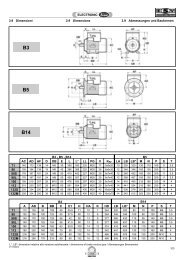
Drive DesignAbreviations used in Formulaeh b = Effective line difference (mm)C = Drive centre distance provisional (mm)C nom = Drive centre distance actual (mm)2 c = Difference between effective andpitch diameter(mm)c 1 = Arc of contact correction factorc 2 = Drive service factorc 3 = <strong>Belt</strong> length correction factorD e = Effective diameter of larger pulley (mm)d e = Effective diameter of smaller pulley (mm)de 1 = Effective diameter of driver pulley (mm)de 2 = Effective diameter of driven pulley (mm)D p = Pitch diameter of larger pulley (mm)d p = Pitch diameter of smaller pulley (mm)E = <strong>Belt</strong> deflection per 100 mm span length (mm)E a = <strong>Belt</strong> deflection <strong>for</strong> a given span length (mm)f = Load used to set belt tension per rib (N)k = Constant <strong>for</strong> calculation of centrifugal <strong>for</strong>ceL es = Standard belt effective length (mm)L eth = Calculated belt effective length (mm)N = Speed of larger pulley (r.p.m.)n = Speed of smaller pulley (r.p.m.)n 1 = Speed of driver pulley (r.p.m.)n 2 = Speed of driven pulley (r.p.m.)P = Motor or normal running power (kW)P B = Design power (kW)P N = Power rating per rib (kW)r = Speed ratioS = Drive span length (mm)S a = Static shaft loading (N)T = Static belt tension per rib (N)v = <strong>Belt</strong> speed (m/s)x = Minimum allowance above drive centre distanceC nom <strong>for</strong> belt stretch and wear(mm)y = Minimum allowance below drive centre distanceC nom <strong>for</strong> belt installation and tensioning (mm)z = Number of ribsα = Angle of belt run = 90° -2(degrees)β = Arc of contact on smaller pulley (degrees)d eD pβC nom8
Drive DesignOptibelt Power Ratings P N - Arc of Contact Correction Factor c 1Optibelt power ratings P N shown in tables 5 to 9 are based oninternationally recognised <strong>for</strong>mulae. These <strong>for</strong>mulae contain materialconstants which must be used in accordance with the practicesof the individual manufacturers. The P N power rating <strong>for</strong>mula isbased on a specific tension ratio between the tight and slack sidesof the belt. The power rating tables refer to the smallest loadedpulley in the drive. The belt power ratings from the tables are given<strong>for</strong>:● the effective diameter of smaller pulley d e● the speed of smaller pulley n.● the speed ratio r● the arc of contact of the belt on smaller pulley ß =180 o● the ideal belt length <strong>for</strong> the particular belt section.From the given drive data the power rating per rib P N can be foundwhich must then be modified by application of the arc of contactand belt length correction factors c 1 and c 3 .Intermediate values can be found by linear interpolation.The arc of contact correction factor c 1 corrects the power rating P Nwhen the arc of contact of the belt around the smaller pulley d e issmaller than ß =180o.Table 1D e – d eC nomβ ≈ c 10 180° 1.000.05 177° 1.000.10 174° 1.000.15 171° 0.990.20 168° 0.990.25 165° 0.990.30 162° 0.990.35 160° 0.990.40 156° 0.980.45 153° 0.980.50 150° 0.980.55 147° 0.970.60 144° 0.970.65 141° 0.970.70 139° 0.960.75 136° 0.960.80 133° 0.950.85 130° 0.950.90 126° 0.940.95 123° 0.941.00 119° 0.931.05 115° 0.921.10 112° 0.921.15 109° 0.911.20 106° 0.901.25 103° 0.891.30 100° 0.891.35 96° 0.871.40 92° 0.861.45 88° 0.851.50 84° 0.831.55 80° 0.821.60 77° 0.80Intermediate values should be found by linear interpolation!9
Drive Design<strong>Belt</strong> Length Correction Factor c 3The belt length correction factor c 3 takes into account the bendingstresses in the particular belt section in relationship to a standardeffective length.This results in the following relationships:ribbed belt length used > standard effective length c 3 > 1.0ribbed belt length used = standard effective length c 3 = 1.0ribbed belt length used < standard effective length c 3 < 1.0c 3 = 1 +L(es) L eff[ ]0.09 – 1 · 2.4L es – ribbed belt length usedL eff = standard effective lengthTable 2Section PHSection PJEffective lengthEffective lengthEffective lengthEffective lengthL es c 3 L es c 3 L es c 3 L esc 3(mm)(mm)(mm)(mm)698 0.96735 0.97762 0.98813 1.00858 1.01864 1.01886 1.01914 1.02955 1.03965 1.03975 1.03990 1.031016 1.041080 1.061092 1.061096 1.061168 1.071194 1.081200 1.081222 1.081230 1.091244 1.091262 1.091270 1.091285 1.101290 1.101301 1.101309 1.101316 1.101321 1.101333 1.101371 1.111397 1.111439 1.121475 1.131600 1.151854 1.181895 1.181915 1.191930 1.191956 1.191992 1.202083 1.212155 1.22280 0.74330 0.76356 0.78362 0.78381 0.79406 0.80414 0.81432 0.82457 0.83483 0.84508 0.85559 0.87584 0.88610 0.89660 0.90711 0.92723 0.92762 0.93813 0.95836 0.95864 0.96914 0.97955 0.98965 0.981016 1.001092 1.011105 1.011110 1.011123 1.021130 1.021150 1.021168 1.031194 1.031200 1.031222 1.041244 1.041262 1.041270 1.041285 1.051301 1.051309 1.051316 1.051321 1.051333 1.051355 1.061371 1.061397 1.061428 1.071439 1.071475 1.081549 1.091600 1.101651 1.101663 1.101752 1.121780 1.121854 1.131895 1.131910 1.141915 1.141930 1.141956 1.141965 1.141981 1.141992 1.142083 1.162155 1.172210 1.172337 1.182489 1.2010Non standard lengths on request.
Drive Design<strong>Belt</strong> Length Correction Factor c 3Table 2Section PKSection PLSection PMEffectivelengthLes(mm)EffectiveEffectiveEffectiveEffectiveEffectivec 3 lengthL c 3 lengthL c 3 lengthLc 3 lengthLc 3 lengthLc 3eseseseses(mm)(mm)(mm)(mm)(mm)605 0.80625 0.81630 0.81648 0.81675 0.82698 0.82725 0.83735 0.83763 0.84775 0.85780 0.85790 0.85795 0.85800 0.85805 0.85812 0.85815 0.85825 0.86830 0.86835 0.86841 0.86845 0.87850 0.87858 0.87865 0.87870 0.87872 0.87875 0.87880 0.87884 0.87886 0.87890 0.88905 0.88913 0.88920 0.88925 0.88930 0.89935 0.89940 0.89945 0.89950 0.89954 0.89962 0.89966 0.89970 0.89975 0.89985 0.89990 0.89995 0.901000 0.901005 0.901010 0.901015 0.901020 0.901025 0.901045 0.911065 0.911080 0.911090 0.911100 0.921110 0.921120 0.931125 0.931140 0.931150 0.931160 0.931165 0.931180 0.941190 0.941215 0.941230 0.941245 0.951260 0.951270 0.951285 0.951290 0.951301 0.961325 0.961330 0.961345 0.961371 0.961397 0.971415 0.971420 0.981439 0.981450 0.981460 0.981475 0.981520 0.991540 0.991550 0.991560 0.991570 1.001600 1.001610 1.001655 1.011690 1.011725 1.021755 1.021854 1.031885 1.031900 1.041915 1.041935 1.041980 1.051992 1.052030 1.052040 1.052050 1.052080 1.062100 1.062120 1.062145 1.062155 1.072170 1.072230 1.07954 0.83991 0.841075 0.861194 0.881270 0.891333 0.901371 0.911397 0.911422 0.911562 0.931613 0.941664 0.951715 0.951764 0.961803 0.961841 0.971943 0.981981 0.982020 0.992070 0.992096 1.002134 1.002197 1.012235 1.012324 1.022362 1.022476 1.032515 1.032705 1.052743 1.052845 1.062895 1.072921 1.072997 1.073086 1.083124 1.083289 1.093327 1.103492 1.113696 1.124051 1.144191 1.154470 1.164622 1.175029 1.195385 1.216096 1.242286 0.872388 0.882515 0.892693 0.912832 0.922921 0.923010 0.933124 0.943327 0.953531 0.963734 0.984089 1.004191 1.004470 1.014648 1.025029 1.045410 1.066121 1.086883 1.117646 1.138408 1.169169 1.189931 1.1910693 1.2112217 1.2413741 1.2715266 1.30Non standard lengths on request.11
Drive DesignMinimum Allowances x/y above and below Drive Centre Distance C nomTable 3Effective lengthMinimum allo-Minimum allowance y (mm) – <strong>for</strong> ease of fittingwance x (mm)<strong>for</strong> tensioningand retensioning Section PH Section PJ Section PK Section PL Section PM≤ 500 10 10 10 — — —> 500 ≤ 1000 15 15 15 20 25 —> 1000 ≤ 1500 20 15 15 20 25 —> 1500 ≤ 2000 25 15 15 20 25 —> 2000 ≤ 2500 30 20 20 20 25 40> 2500 ≤ 3000 35 20 20 25 30 40> 3000 ≤ 4000 45 — — 25 30 45> 4000 ≤ 5000 55 — — 30 35 45> 5000 ≤ 6000 65 — — 30 35 50> 6000 ≤ 7500 85 — — — — 55> 7500 ≤ 9000 100 — — — — 60> 9000 ≤ 10 500 115 — — — — 65> 10 500 ≤ 12 000 130 — — — — 75> 12 000 ≤ 13 500 150 — — — — 80> 13 500 ≤ 15 266 165 — — — — 90C nom12
Drive DesignDrive Service Factor c 2The drive service factor c 2 takes into account the length of time thedrive is operational in a 24 hour period and the type of driver anddriven units. It applies exclusively to two pulley drives and cannotbe applied <strong>for</strong> other working conditions, such as drives with idlerand guide pulleys. Pages 26 and 27 give the design bases <strong>for</strong>drives with more than two pulleys. Adverse operating conditionssuch as high ambient temperatures, high humidity, the use of anidler pulley, etc., are not considered due to the obvious difficultiesin creating factor tables to cater <strong>for</strong> every eventuality. The Tablegiven below should thus be regarded as a guideline. In specialTable 4cases e.g. high starting load (direct starting of fans), drives withhigh starting frequency, unusual shock loading, or the regularacceleration/ deceleration of mass, the load factor should beincreased.Typical valueWhere the starting load is more than 1.8 times thestandard running load, the minimum service factor c 2should be determined by dividing the starting loadfactor by 1.5. Example: Starting load factor M A =3.0;c 2 selected 2.0. Where the application is especiallyproblematical please consult our engineers.AC and three-phase motorswith normal starting load (up to1.8 times normal running load)e.g. synchronous and singlephasemotors with auxiliaryphase, three-phase motors withdirect on-line start, star delta orcommutator starter, DC shuntwound motors, internal combustionengines and turbines n>600 min -1 .Types of Prime MoverHours per day dutyAC and three-phase motorswith high starting load (morethan 1.8 times normal runningload) e.g. single phase motorswith high starting torque, DCmotors series and compoundwound, internal combustionengines and turbines n ≤ 600min -1 .Types of Driven Machine10 and over 1010 and over 10under to16over 16under to 16over 16Light dutyLight dutyAgitators <strong>for</strong> liquids with uni<strong>for</strong>m consistency,generators up to 0.05 kW, small conveyor belts<strong>for</strong> lightweight material, fans up to 0.05 kW,rotary pumps up to 0.05 kWConveyor belts <strong>for</strong> lightweight material, fansfrom 0.06 to 0.1 kW, rotary pumps from 0.06to 0.1 kW1.1 1.1 1.2 1.1 1.2 1.31.1 1.2 1.3 1.2 1.3 1.4Medium dutyHeavy dutyVibrating screens, mine fans, agitators <strong>for</strong> liquidswith fluctuating consistency, compressors,screw presses, woodworking machinery, conveyorbelts <strong>for</strong> heavy material, elevators, conveyorbelts, fans above 0.8 kW, drills, millingmachines, grinding machines, light lathes,bakery machinery, circular spinning frames,rotary pumps above 0.11 kW, laundry machineryKneaders, mills, mixers, pumps, drying drums,general milling equipment, centrifuges, agitators<strong>for</strong> plastic materials with fluctuating consistency,bucket conveyors, centrifugal fans, parallelplaning machines, weaving looms1.2 1.3 1.4 1.3 1.4 1.51.3 1.4 1.5 1.4 1.5 1.6Heavy dutyPaper making machinery, plate conveyors, slagmills, calenders, drilling rigs, heavy duty lathes,punches, shears, draw benches, piston pumpsup to 2 cylinder1.4 1.5 1.6 1.5 1.7 1.8Extra heavy dutyDredgers, heavy duty grinders, rolling mills,mixers, sawmills, calenders1.6 1.7 1.8 1.6 1.8 2.013
Drive DesignA Guide to Selecting <strong>Ribbed</strong> <strong>Belt</strong> SectionsBy using the following diagram and considering economy and sizeit is possible to determine the best <strong>Ribbed</strong> <strong>Belt</strong> section. Optimumutilisation of power and efficiency is achieved by the selection ofthe largest possible pulley diameter in relation to the section used.The limits to the permissible circumferential speeds must be observed.Section PH v max = 60 m/sSection PJ v max = 60 m/sSection PK v max = 50 m/sSection PL v max = 40 m/sSection PM v max = 30 m/sExperience has shown that minimum pulley diameters should beavoided. Such drives are not cheap and require large face widths.In such borderline cases the use of the next smaller belt section onsimilar pulley diameters will often save both cost and space.In these boundary areas, it is advisable to design the drive withboth sections.Diagram 1Small pulley speed n k (min -1 )14Design power P B = P x c 2 (kW)
Drive DesignFormulae and Drive Design MethodPrime MoverDrive ConditionsOperational hours per day:approx. 8 hoursNumber of starts: approx. 20 per dayNormal ambient temperature, noexposure to oil and waterDriven MachineElectric motorP = 13 kWn 1 = 2440 min -1Start up: directStarting torque: M A = 2.7 M NDrive centre distance: between 250 and300 mm acceptableEffective diameter of driver pulley:d e1 = 140 mmGrinding spindleP = 13 kWn 2 = 3100 ± 100 min -1Start up: from idlingFormulaeDrive service factorc 2 from Table 4 page 13Calculation Examplec 2 = 1.8Design powerP B = P · c 2P B = 13 · 1.8 = 23.40 kW<strong>Belt</strong> section selectionfrom Diagram 1 page 14Profil PLSpeed ratior =n 1 D= p=d e2 + 2 b en 2 d p d e1 + 2 b eh b see page 242440r = = 0.7693173Effective diameters of ribbed belt pulleysd e1 Page 37d e2 = d e1 · r + 2 b e (r – 1)when d e2 is known:d e2 1d e1 = + 2 h b – 1rr( )d e1 = 123 mm selectedd e2 = 123 mm · 0.769 + 2 · 3.5 (0.769 – 1) = 92.97 mmd e2 = 93 mm see page 3715
Drive DesignFormulae and Drive Design MethodFormulaeCalculation ExampleRecalculation of speed of driven machineD r pactual =93 + 2 · 3.5d = 0.769e2 + 2 b er actual =d=123 + 2 · 3.5pnn24402 actual = = 3173 min -1n 2 actual = 10.769r actualRequired:3100 ± 100 min -1(Calculated speed meetsrequirement)d e1 + 2 b eC nom ≈ 380 – ≈ 367.65 mmDrive centre distance (suggested)Empfehlung: c > 0.7 (D e + d e )c < 2 (D e + d e )c = 380 mm suggestedEffective length of <strong>Ribbed</strong> <strong>Belt</strong>L eth ≈ 2 c + 1.57 (D e + d e ) + (D e – d e ) 24 cActual:β πα x πL eth = 2 c · sin + (D e + d e ) + (D e + d e )2 2180°(123 – 93) 2L eth ≈ 2 · 380 + 1.57 · (123 + 93) +4 · 380Nearest standard length from page 7 selectedL es = 1075 mm≈ 1099.7 mmDrive centre distanceCalculated from L es and L ethL es – L eth(when L es > L eth ) C nom ≈ C +2L es – L eth(when L es < L eth ) C nom ≈ C –2actual: πL es – (D e + d e )2C nom = +4[L es – (D e + d e )π24]2–(D e – d e ) 281099.7 – 10752Minimum allowances x/y above and belod drivecentre distance C nomx/y from table 3 page 11x ≥ 20 mm / y ≥ 25 mm<strong>Belt</strong> speedd pk · n k (d bk + 2 · h b ) · n k(93 + 2 · 3.5) · 3173v = = v = = 16.61 m/s19100 191001910016
Drive DesignFormulae and Drive Design MethodFormulaeCalculation ExampleArc of contact and arc of contact correction factorD e – d e123 – 93= 0.082C nom368Approximate β° and c 1 from table 1 page 9β ≈ 175°linearly interpolatedβ D e – d ec 1 = 1.0}Actual: cos =2 2 C nom<strong>Belt</strong> length correction factorc 3 from table 2 page 11c 3 = 0.86Power rating per rib{d e = 93 mmP N <strong>for</strong> n = 3173 min -1 Section PLr∗ =1from table 8 page 21= 1.30.769When a speed up drive is involved use the <strong>for</strong>mula marked ∗to generate ”r“ <strong>for</strong> use with the power rating tables.P N = 2.28 + 0.2 = 2.48 kWNumber of ribsz =P · c 213 · 1.8z = = 10.97P N · c 1 · c 3 2.48 · 1.0 · 0.86Suqaested:1 Optibelt-RB <strong>Ribbed</strong> <strong>Belt</strong> 12 PL 1075Static belt tension per rib500 · (2.03 – c 1 ) · P BT ≈ + k · v 2c 1 · z · v500 · (2.03 – 1.0) · 23.4T ≈ + 0.036 · 16.6 2 ≈ 70 N1.0 · 12 · 16.6k from diagram 2 page 41Minimum static shaft loadingβS a ≈ 2 T · sin · z S a ≈ 2 · 70 · 0.9986 · 12 ≈ 1678 N2<strong>Belt</strong> deflection <strong>for</strong> a given span lengthE · LE a ≈100E from diagram 2 page 41βL = C nom · sin2For explanation see chapteron tensioning on page 402.5 · 367.0E a ≈≈ 9 mm100E ≈ 2.5 mmL = 367.6 · 0.9986 = 367.0 mm17
Section PHPower Ratings P N (kW) per Rib <strong>for</strong> β = 180° and L eff = 813 mmTable 5v (m/s)n(min -1 )Effective diameter of the small pulley d e (mm)13 17 20 25 31.5 35.5 40 45 50 63 71 80Additional power per rib<strong>for</strong> speed ratio r.1.01 1.06 1.27 >1.57to to to1.05 1.26 1.57700 0.01 0.02 0.02 0.03 0.04 0.05 0.05 0.06 0.07 0.09 0.10 0.11950 0.01 0.02 0.03 0.04 0.05 0.06 0.07 0.08 0.09 0.11 0.13 0.151450 0.02 0.03 0.04 0.06 0.08 0.09 0.10 0.11 0.13 0.17 0.19 0.212850 0.03 0.05 0.07 0.10 0.14 0.16 0.18 0.21 0.23 0.30 0.34 0.38 0.01 0.01100 0.00 0.00 0.00 0.01 0.01 0.01 0.01 0.01 0.01 0.02 0.02 0.02300 0.01 0.01 0.01 0.01 0.02 0.02 0.02 0.03 0.03 0.04 0.05 0.05500 0.01 0.01 0.02 0.02 0.03 0.03 0.04 0.04 0.05 0.06 0.07 0.08700 0.01 0.02 0.02 0.03 0.04 0.05 0.05 0.06 0.07 0.09 0.10 0.11900 0.01 0.02 0.03 0.04 0.05 0.06 0.07 0.08 0.08 0.11 0.12 0.141000 0.01 0.02 0.03 0.04 0.05 0.06 0.07 0.08 0.09 0.12 0.13 0.151100 0.02 0.02 0.03 0.04 0.06 0.07 0.08 0.09 0.10 0.13 0.15 0.171200 0.02 0.03 0.03 0.05 0.06 0.07 0.08 0.10 0.11 0.14 0.16 0.181300 0.02 0.03 0.04 0.05 0.07 0.08 0.09 0.10 0.12 0.15 0.17 0.191400 0.02 0.03 0.04 0.05 0.07 0.08 0.10 0.11 0.13 0.16 0.18 0.211500 0.02 0.03 0.04 0.06 0.08 0.09 0.10 0.12 0.13 0.17 0.19 0.221600 0.02 0.03 0.04 0.06 0.08 0.10 0.11 0.13 0.14 0.18 0.20 0.231700 0.02 0.04 0.05 0.06 0.09 0.10 0.12 0.13 0.15 0.19 0.22 0.241800 0.02 0.04 0.05 0.07 0.09 0.11 0.12 0.14 0.16 0.20 0.23 0.261900 0.02 0.04 0.05 0.07 0.10 0.11 0.13 0.15 0.16 0.21 0.24 0.272000 0.02 0.04 0.05 0.07 0.10 0.12 0.13 0.15 0.17 0.22 0.25 0.282100 0.02 0.04 0.06 0.08 0.10 0.12 0.14 0.16 0.18 0.23 0.26 0.292200 0.03 0.04 0.06 0.08 0.11 0.13 0.15 0.17 0.19 0.24 0.27 0.31 0.012300 0.03 0.05 0.06 0.08 0.11 0.13 0.15 0.17 0.19 0.25 0.28 0.32 0.012400 0.03 0.05 0.06 0.09 0.12 0.14 0.16 0.18 0.20 0.26 0.29 0.33 0.012500 0.03 0.05 0.06 0.09 0.12 0.14 0.16 0.19 0.21 0.27 0.30 0.34 0.012600 0.03 0.05 0.07 0.09 0.13 0.15 0.17 0.19 0.22 0.28 0.31 0.35 0.012700 0.03 0.05 0.07 0.10 0.13 0.15 0.17 0.20 0.22 0.29 0.32 0.37 0.012800 0.03 0.05 0.07 0.10 0.13 0.16 0.18 0.21 0.23 0.30 0.33 0.38 0.01 0.012900 0.03 0.06 0.07 0.10 0.14 0.16 0.18 0.21 0.24 0.30 0.34 0.39 0.01 0.013000 0.03 0.06 0.08 0.10 0.14 0.17 0.19 0.22 0.24 0.31 0.35 0.40 0.01 0.013100 0.03 0.06 0.08 0.11 0.15 0.17 0.20 0.22 0.25 0.32 0.37 0.41 0.01 0.013200 0.03 0.06 0.08 0.11 0.15 0.17 0.20 0.23 0.26 0.33 0.38 0.42 0.01 0.013300 0.03 0.06 0.08 0.11 0.15 0.18 0.21 0.24 0.27 0.34 0.39 0.43 0.01 0.013400 0.04 0.06 0.08 0.12 0.16 0.18 0.21 0.24 0.27 0.35 0.39 0.44 0.01 0.013500 0.04 0.06 0.09 0.12 0.16 0.19 0.22 0.25 0.28 0.36 0.40 0.46 0.01 0.013600 0.04 0.07 0.09 0.12 0.17 0.19 0.22 0.26 0.29 0.37 0.41 0.47 0.01 0.013700 0.04 0.07 0.09 0.13 0.17 0.20 0.23 0.26 0.29 0.38 0.42 0.48 0.01 0.013800 0.04 0.07 0.09 0.13 0.17 0.20 0.23 0.27 0.30 0.38 0.43 0.49 0.01 0.01 0.013900 0.04 0.07 0.09 0.13 0.18 0.21 0.24 0.27 0.31 0.39 0.44 0.50 0.01 0.01 0.014000 0.04 0.07 0.10 0.13 0.18 0.21 0.24 0.28 0.31 0.40 0.45 0.51 0.01 0.01 0.014100 0.04 0.07 0.10 0.14 0.19 0.22 0.25 0.29 0.32 0.41 0.46 0.52 0.01 0.01 0.014200 0.04 0.08 0.10 0.14 0.19 0.22 0.25 0.29 0.33 0.42 0.47 0.53 0.01 0.01 0.014400 0.04 0.08 0.10 0.15 0.20 0.23 0.26 0.30 0.34 0.43 0.49 0.55 0.01 0.01 0.014600 0.04 0.08 0.11 0.15 0.21 0.24 0.27 0.31 0.35 0.45 0.51 0.57 0.01 0.01 0.014800 0.05 0.08 0.11 0.16 0.21 0.25 0.28 0.33 0.37 0.47 0.52 0.59 0.01 0.01 0.015000 0.05 0.09 0.12 0.16 0.22 0.26 0.29 0.34 0.38 0.48 0.54 0.60 0.01 0.01 0.015200 0.05 0.09 0.12 0.17 0.23 0.26 0.30 0.35 0.39 0.50 0.56 0.62 0.01 0.01 0.015400 0.05 0.09 0.12 0.17 0.24 0.27 0.31 0.36 0.40 0.51 0.57 0.64 0.01 0.01 0.015600 0.05 0.09 0.13 0.18 0.24 0.28 0.32 0.37 0.42 0.53 0.59 0.66 0.01 0.01 0.015800 0.05 0.10 0.13 0.18 0.25 0.29 0.33 0.38 0.43 0.54 0.61 0.67 0.01 0.01 0.016000 0.05 0.10 0.13 0.19 0.26 0.30 0.34 0.39 0.44 0.56 0.62 0.69 0.01 0.01 0.016200 0.06 0.10 0.14 0.19 0.26 0.31 0.35 0.40 0.45 0.57 0.64 0.70 0.01 0.01 0.016400 0.06 0.11 0.14 0.20 0.27 0.31 0.36 0.41 0.46 0.58 0.65 0.72 0.01 0.01 0.016600 0.06 0.11 0.14 0.20 0.28 0.32 0.37 0.42 0.47 0.60 0.66 0.73 0.01 0.01 0.026800 0.06 0.11 0.15 0.21 0.29 0.33 0.38 0.43 0.49 0.61 0.68 0.75 0.01 0.01 0.027000 0.06 0.11 0.15 0.21 0.29 0.34 0.39 0.44 0.50 0.62 0.69 0.76 0.01 0.01 0.027200 0.06 0.12 0.15 0.22 0.30 0.35 0.40 0.45 0.51 0.63 0.70 0.77 0.01 0.01 0.027400 0.06 0.12 0.16 0.22 0.31 0.35 0.41 0.46 0.52 0.65 0.71 0.78 0.01 0.01 0.027600 0.06 0.12 0.16 0.23 0.31 0.36 0.42 0.47 0.53 0.66 0.73 0.79 0.01 0.01 0.027800 0.06 0.12 0.17 0.23 0.32 0.37 0.42 0.48 0.54 0.67 0.74 0.80 0.01 0.01 0.028000 0.07 0.13 0.17 0.24 0.33 0.38 0.43 0.49 0.55 0.68 0.75 0.81 0.01 0.01 0.028200 0.07 0.13 0.17 0.24 0.33 0.38 0.44 0.50 0.56 0.69 0.76 0.82 0.01 0.01 0.028400 0.07 0.13 0.18 0.25 0.34 0.39 0.45 0.51 0.57 0.70 0.77 0.83 0.01 0.02 0.028600 0.07 0.13 0.18 0.25 0.34 0.40 0.46 0.52 0.58 0.71 0.78 0.83 0.01 0.02 0.028800 0.07 0.13 0.18 0.26 0.35 0.41 0.46 0.53 0.59 0.72 0.78 0.84 0.01 0.02 0.029000 0.07 0.14 0.18 0.26 0.36 0.41 0.47 0.54 0.59 0.73 0.79 0.85 0.01 0.02 0.029200 0.07 0.14 0.19 0.27 0.36 0.42 0.48 0.54 0.60 0.74 0.80 0.85 0.01 0.02 0.029400 0.07 0.14 0.19 0.27 0.37 0.43 0.49 0.55 0.61 0.74 0.81 0.86 0.01 0.02 0.029600 0.07 0.14 0.19 0.28 0.38 0.43 0.50 0.56 0.62 0.75 0.81 0.86 0.01 0.02 0.029800 0.08 0.15 0.20 0.28 0.38 0.44 0.50 0.57 0.63 0.76 0.82 0.86 0.01 0.02 0.0210000 0.08 0.15 0.20 0.28 0.39 0.45 0.51 0.58 0.64 0.77 0.82 0.86 0.01 0.02 0.0210300 0.08 0.15 0.21 0.29 0.40 0.46 0.52 0.59 0.65 0.77 0.83 0.86 0.01 0.02 0.0210600 0.08 0.15 0.21 0.30 0.40 0.47 0.53 0.60 0.66 0.78 0.83 0.86 0.01 0.02 0.0210900 0.08 0.16 0.21 0.30 0.41 0.48 0.54 0.61 0.67 0.79 0.84 0.86 0.01 0.02 0.0211500 0.08 0.16 0.22 0.32 0.43 0.49 0.56 0.63 0.69 0.80 0.84 0.84 0.02 0.02 0.0312100 0.09 0.17 0.23 0.33 0.44 0.51 0.58 0.65 0.70 0.81 0.83 0.82 0.02 0.02 0.0312500 0.09 0.17 0.24 0.34 0.45 0.52 0.59 0.66 0.71 0.81 0.83 0.80 0.02 0.02 0.03Where v >60 m/s, please consult our Applications Engineersv (m/s)18
Section PJPower Ratings P N (kW) per Rib <strong>for</strong> β = 180° and L eff = 1016 mmTable 6v (m/s)n(min -1 )Effective diameter of the small pulley d e (mm)20 25 31.5 35.5 40 45 50 63 71 80 90 100 112 125 140 160Additional power per rib<strong>for</strong> speed ratio r.1.01 1.06 1.27 >1.57to to to1.05 1.26 1.57700 0.04 0.05 0.07 0.08 0.10 0.11 0.13 0.16 0.18 0.21 0.24 0.26 0.30 0.33 0.37 0.42 0.01950 0.05 0.07 0.09 0.11 0.13 0.14 0.16 0.21 0.24 0.28 0.31 0.35 0.39 0.44 0.49 0.56 0.01 0.011450 0.06 0.09 0.13 0.15 0.18 0.21 0.24 0.31 0.35 0.40 0.45 0.51 0.57 0.63 0.71 0.81 0.01 0.01 0.012850 0.11 0.16 0.23 0.28 0.32 0.38 0.43 0.56 0.64 0.72 0.82 0.91 1.02 1.14 1.27 1.43 0.01 0.02 0.02100 0.01 0.01 0.01 0.02 0.02 0.02 0.02 0.03 0.03 0.04 0.04 0.05 0.05 0.06 0.06 0.07300 0.02 0.03 0.03 0.04 0.05 0.05 0.06 0.08 0.09 0.10 0.11 0.12 0.14 0.16 0.17 0.20500 0.03 0.04 0.05 0.06 0.07 0.08 0.09 0.12 0.14 0.16 0.18 0.20 0.22 0.25 0.27 0.31700 0.04 0.05 0.07 0.08 0.10 0.11 0.13 0.16 0.18 0.21 0.24 0.26 0.30 0.33 0.37 0.42 0.01900 0.04 0.06 0.09 0.10 0.12 0.14 0.16 0.20 0.23 0.26 0.30 0.33 0.37 0.42 0.46 0.53 0.01 0.011100 0.05 0.07 0.10 0.12 0.14 0.16 0.19 0.24 0.28 0.31 0.36 0.40 0.44 0.50 0.56 0.63 0.01 0.011200 0.05 0.08 0.11 0.13 0.15 0.18 0.20 0.26 0.30 0.34 0.38 0.43 0.48 0.54 0.60 0.68 0.01 0.011300 0.06 0.09 0.12 0.14 0.16 0.19 0.22 0.28 0.32 0.36 0.41 0.46 0.52 0.58 0.64 0.73 0.01 0.01 0.011400 0.06 0.09 0.13 0.15 0.18 0.20 0.23 0.30 0.34 0.39 0.44 0.49 0.55 0.62 0.69 0.78 0.01 0.01 0.011500 0.07 0.10 0.14 0.16 0.19 0.22 0.24 0.32 0.36 0.41 0.47 0.52 0.59 0.65 0.73 0.83 0.01 0.01 0.011600 0.07 0.10 0.14 0.17 0.20 0.23 0.26 0.34 0.38 0.44 0.49 0.55 0.62 0.69 0.77 0.88 0.01 0.01 0.011700 0.07 0.11 0.15 0.18 0.21 0.24 0.27 0.36 0.41 0.46 0.52 0.58 0.65 0.73 0.82 0.93 0.01 0.01 0.011800 0.08 0.11 0.16 0.19 0.22 0.25 0.29 0.37 0.43 0.48 0.55 0.61 0.69 0.77 0.86 0.98 0.01 0.01 0.011900 0.08 0.12 0.17 0.20 0.23 0.26 0.30 0.39 0.45 0.51 0.58 0.64 0.72 0.80 0.90 1.02 0.01 0.01 0.012000 0.08 0.12 0.17 0.20 0.24 0.28 0.31 0.41 0.47 0.53 0.60 0.67 0.75 0.84 0.94 1.07 0.01 0.01 0.012100 0.08 0.13 0.18 0.21 0.25 0.29 0.33 0.43 0.49 0.56 0.63 0.70 0.79 0.88 0.98 1.11 0.01 0.01 0.022200 0.09 0.13 0.19 0.22 0.26 0.30 0.34 0.45 0.51 0.58 0.65 0.73 0.82 0.91 1.02 1.16 0.01 0.01 0.022300 0.09 0.14 0.19 0.23 0.27 0.31 0.35 0.46 0.53 0.60 0.68 0.76 0.85 0.95 1.06 1.20 0.01 0.01 0.022400 0.09 0.14 0.20 0.24 0.28 0.32 0.37 0.48 0.55 0.62 0.71 0.79 0.88 0.98 1.10 1.24 0.01 0.01 0.022500 0.10 0.15 0.21 0.25 0.29 0.34 0.38 0.50 0.57 0.65 0.73 0.82 0.91 1.02 1.14 1.29 0.01 0.01 0.022600 0.10 0.15 0.22 0.26 0.30 0.35 0.39 0.52 0.59 0.67 0.76 0.84 0.94 1.05 1.17 1.33 0.01 0.01 0.022700 0.10 0.16 0.22 0.26 0.31 0.36 0.41 0.53 0.61 0.69 0.78 0.87 0.98 1.09 1.21 1.37 0.01 0.02 0.022800 0.11 0.16 0.23 0.27 0.32 0.37 0.42 0.55 0.63 0.71 0.81 0.90 1.01 1.12 1.25 1.41 0.01 0.02 0.022900 0.11 0.17 0.24 0.28 0.33 0.38 0.43 0.57 0.65 0.73 0.83 0.93 1.04 1.15 1.28 1.45 0.01 0.02 0.023000 0.11 0.17 0.24 0.29 0.34 0.39 0.45 0.58 0.67 0.76 0.86 0.95 1.07 1.19 1.32 1.49 0.01 0.02 0.023100 0.11 0.17 0.25 0.30 0.35 0.40 0.46 0.60 0.68 0.78 0.88 0.98 1.10 1.22 1.35 1.53 0.01 0.02 0.023200 0.12 0.18 0.26 0.30 0.36 0.41 0.47 0.62 0.70 0.80 0.90 1.01 1.13 1.25 1.39 1.56 0.01 0.02 0.023300 0.12 0.18 0.26 0.31 0.37 0.43 0.48 0.63 0.72 0.82 0.93 1.03 1.15 1.28 1.42 1.60 0.01 0.02 0.023400 0.12 0.19 0.27 0.32 0.38 0.44 0.50 0.65 0.74 0.84 0.95 1.06 1.18 1.31 1.46 1.64 0.01 0.02 0.023500 0.13 0.19 0.28 0.33 0.38 0.45 0.51 0.67 0.76 0.86 0.97 1.08 1.21 1.34 1.49 1.67 0.01 0.02 0.033600 0.13 0.20 0.28 0.34 0.39 0.46 0.52 0.68 0.78 0.88 1.00 1.11 1.24 1.37 1.52 1.71 0.01 0.02 0.033700 0.13 0.20 0.29 0.34 0.40 0.47 0.53 0.70 0.80 0.90 1.02 1.13 1.27 1.40 1.55 1.74 0.02 0.02 0.033800 0.13 0.21 0.30 0.35 0.41 0.48 0.55 0.71 0.81 0.92 1.04 1.16 1.29 1.43 1.59 1.77 0.02 0.02 0.033900 0.14 0.21 0.30 0.36 0.42 0.49 0.56 0.73 0.83 0.94 1.07 1.18 1.32 1.46 1.62 1.80 0.02 0.02 0.034000 0.14 0.21 0.31 0.37 0.43 0.50 0.57 0.75 0.85 0.96 1.09 1.21 1.35 1.49 1.65 1.84 0.02 0.02 0.034100 0.14 0.22 0.32 0.37 0.44 0.51 0.58 0.76 0.87 0.98 1.11 1.23 1.37 1.52 1.68 1.87 0.02 0.02 0.034200 0.14 0.22 0.32 0.38 0.45 0.52 0.59 0.78 0.89 1.00 1.13 1.26 1.40 1.55 1.70 1.90 0.02 0.02 0.034300 0.15 0.23 0.33 0.39 0.46 0.53 0.61 0.79 0.90 1.02 1.15 1.28 1.42 1.57 1.73 1.92 0.02 0.02 0.034400 0.15 0.23 0.33 0.40 0.47 0.54 0.62 0.81 0.92 1.04 1.18 1.30 1.45 1.60 1.76 1.95 0.02 0.02 0.034500 0.15 0.23 0.34 0.40 0.48 0.55 0.63 0.82 0.94 1.06 1.20 1.33 1.47 1.63 1.79 1.98 0.02 0.03 0.034600 0.15 0.24 0.35 0.41 0.48 0.56 0.64 0.84 0.95 1.08 1.22 1.35 1.50 1.65 1.81 2.00 0.02 0.03 0.034700 0.16 0.24 0.35 0.42 0.49 0.57 0.65 0.85 0.97 1.10 1.24 1.37 1.52 1.68 1.84 2.03 0.02 0.03 0.034800 0.16 0.25 0.36 0.43 0.50 0.58 0.66 0.87 0.99 1.12 1.26 1.39 1.55 1.70 1.86 2.05 0.02 0.03 0.034900 0.16 0.25 0.37 0.43 0.51 0.59 0.68 0.88 1.01 1.14 1.28 1.42 1.57 1.72 1.89 2.07 0.02 0.03 0.045000 0.16 0.26 0.37 0.44 0.52 0.60 0.69 0.90 1.02 1.16 1.30 1.44 1.59 1.75 1.91 2.09 0.02 0.03 0.045100 0.17 0.26 0.38 0.45 0.53 0.61 0.70 0.91 1.04 1.17 1.32 1.46 1.62 1.77 1.93 2.12 0.01 0.02 0.03 0.045200 0.17 0.26 0.38 0.46 0.54 0.62 0.71 0.93 1.05 1.19 1.34 1.48 1.64 1.79 1.95 2.13 0.01 0.02 0.03 0.045300 0.17 0.27 0.39 0.46 0.55 0.63 0.72 0.94 1.07 1.21 1.36 1.50 1.66 1.82 1.98 2.15 0.01 0.02 0.03 0.045400 0.17 0.27 0.40 0.47 0.55 0.64 0.73 0.96 1.09 1.23 1.38 1.52 1.68 1.84 2.00 2.17 0.01 0.02 0.03 0.045500 0.18 0.28 0.40 0.48 0.56 0.65 0.74 0.97 1.10 1.25 1.40 1.54 1.70 1.86 2.02 2.19 0.01 0.02 0.03 0.045600 0.18 0.28 0.41 0.48 0.57 0.66 0.76 0.98 1.12 1.26 1.42 1.56 1.72 1.88 2.03 2.20 0.01 0.02 0.03 0.045700 0.18 0.28 0.41 0.49 0.58 0.67 0.77 1.00 1.13 1.28 1.44 1.58 1.74 1.90 2.05 2.22 0.01 0.02 0.03 0.045800 0.18 0.29 0.42 0.50 0.59 0.68 0.78 1.01 1.15 1.30 1.45 1.60 1.76 1.92 2.07 2.23 0.01 0.02 0.03 0.046000 0.19 0.29 0.43 0.51 0.60 0.70 0.80 1.04 1.18 1.33 1.49 1.64 1.80 1.95 2.10 2.25 0.01 0.02 0.03 0.046200 0.19 0.30 0.44 0.53 0.62 0.72 0.82 1.07 1.21 1.36 1.52 1.67 1.83 1.99 2.13 2.27 0.01 0.03 0.04 0.046400 0.20 0.31 0.45 0.54 0.64 0.74 0.84 1.09 1.24 1.40 1.56 1.71 1.87 2.02 2.16 2.28 0.01 0.03 0.04 0.056600 0.20 0.32 0.47 0.55 0.65 0.76 0.86 1.12 1.27 1.43 1.59 1.74 1.90 2.05 2.18 2.28 0.01 0.03 0.04 0.056800 0.20 0.32 0.48 0.57 0.67 0.78 0.88 1.15 1.30 1.46 1.62 1.77 1.93 2.07 2.20 2.29 0.01 0.03 0.04 0.057000 0.21 0.33 0.49 0.58 0.68 0.79 0.90 1.17 1.32 1.49 1.65 1.80 1.96 2.10 2.21 2.28 0.01 0.03 0.04 0.057200 0.21 0.34 0.50 0.59 0.70 0.81 0.92 1.20 1.35 1.52 1.68 1.83 1.98 2.12 2.22 2.27 0.01 0.03 0.04 0.057400 0.22 0.35 0.51 0.61 0.71 0.83 0.94 1.22 1.38 1.54 1.71 1.86 2.01 2.13 2.23 0.01 0.03 0.04 0.057600 0.22 0.35 0.52 0.62 0.73 0.85 0.96 1.24 1.40 1.57 1.74 1.88 2.03 2.15 2.23 0.01 0.03 0.04 0.057800 0.22 0.36 0.53 0.63 0.74 0.86 0.98 1.27 1.43 1.60 1.76 1.91 2.05 2.16 2.23 0.01 0.03 0.04 0.068000 0.23 0.37 0.54 0.64 0.76 0.88 1.00 1.29 1.45 1.62 1.79 1.93 2.07 2.17 2.22 0.01 0.03 0.05 0.068200 0.23 0.37 0.55 0.66 0.77 0.90 1.02 1.31 1.48 1.65 1.81 1.95 2.08 2.17 2.21 0.01 0.03 0.05 0.068400 0.24 0.38 0.56 0.67 0.79 0.91 1.04 1.33 1.50 1.67 1.83 1.97 2.09 2.18 2.20 0.01 0.03 0.05 0.068600 0.24 0.39 0.57 0.68 0.80 0.93 1.06 1.36 1.52 1.69 1.85 1.99 2.10 2.18 0.01 0.04 0.05 0.068800 0.24 0.39 0.58 0.69 0.82 0.95 1.07 1.38 1.54 1.71 1.87 2.00 2.11 2.17 0.01 0.04 0.05 0.069000 0.25 0.40 0.59 0.71 0.83 0.96 1.09 1.40 1.56 1.73 1.89 2.01 2.12 2.16 0.01 0.04 0.05 0.069200 0.25 0.41 0.60 0.72 0.84 0.98 1.11 1.42 1.59 1.75 1.91 2.03 2.12 2.15 Where v >60 0.01 0.04 0.05 0.079400 0.26 0.41 0.61 0.73 0.86 0.99 1.13 1.44 1.60 1.77 1.92 2.04 2.12 2.14 m/s, please 0.01 0.04 0.05 0.079700 0.26 0.42 0.63 0.75 0.88 1.02 1.15 1.46 1.63 1.80 1.94 2.05 2.12consult our0.01 0.04 0.05 0.079900 0.26 0.43 0.64 0.76 0.89 1.03 1.17 1.48 1.65 1.81 1.95 2.05 2.11 0.01 0.04 0.06 0.0710100 0.27 0.44 0.64 0.77 0.90 1.05 1.18 1.50 1.67 1.83 1.96 2.06 2.10 Applications 0.01 0.04 0.06 0.0710500 0.27 0.45 0.66 0.79 0.93 1.07 1.21 1.53 1.70 1.85 1.98 2.05 2.07 Engineers 0.01 0.04 0.06 0.08v (m/s)19
Section PKPower Ratings P N (kW) per Rib <strong>for</strong> β = 180° and L eff = 1600 mmTable 7v (m/s)n(min -1 )Effective diameter of the small pulley d e (mm)45 50 63 71 80 90 100 112 125 140 160 180 190 224 250 280 315Additional power per rib<strong>for</strong> speed ratio r.1.01 1.06 1.27 >1.57to to to1.05 1.26 1.5720700 0.17 0.21 0.32 0.38 0.45 0.53 0.61 0.70 0.80 0.91 1.06 1.21 1.28 1.53 1.71 1.92 2.16 0.02 0.02 0.03950 0.21 0.27 0.41 0.49 0.59 0.69 0.79 0.92 1.05 1.20 1.39 1.58 1.68 2.00 2.23 2.50 2.81 0.01 0.02 0.03 0.041450 0.29 0.37 0.58 0.70 0.84 0.99 1.14 1.32 1.51 1.73 2.01 2.28 2.42 2.86 3.19 3.56 3.97 0.01 0.04 0.05 0.062850 0.48 0.63 1.00 1.23 1.48 1.75 2.01 2.32 2.65 3.01 3.47 3.90 4.11 4.75 5.16 5.56 5.91 0.02 0.07 0.10 0.12200 0.06 0.08 0.11 0.13 0.15 0.18 0.20 0.23 0.27 0.30 0.35 0.40 0.42 0.50 0.56 0.63 0.71 0.01 0.01400 0.11 0.13 0.20 0.24 0.28 0.33 0.37 0.43 0.49 0.56 0.65 0.74 0.78 0.93 1.04 1.17 1.32 0.01 0.01 0.02600 0.15 0.19 0.28 0.33 0.40 0.46 0.53 0.61 0.70 0.80 0.93 1.06 1.12 1.33 1.49 1.68 1.89 0.01 0.02 0.03800 0.19 0.23 0.35 0.43 0.51 0.60 0.68 0.79 0.90 1.03 1.20 1.36 1.44 1.72 1.92 2.16 2.42 0.02 0.03 0.031000 0.22 0.28 0.43 0.52 0.61 0.72 0.83 0.96 1.09 1.25 1.45 1.66 1.76 2.09 2.34 2.62 2.93 0.01 0.02 0.03 0.041100 0.24 0.30 0.46 0.56 0.67 0.78 0.90 1.04 1.19 1.36 1.58 1.80 1.91 2.27 2.53 2.84 3.18 0.01 0.03 0.04 0.051200 0.25 0.32 0.50 0.60 0.72 0.85 0.97 1.12 1.28 1.47 1.70 1.94 2.06 2.44 2.73 3.05 3.41 0.01 0.03 0.04 0.051300 0.27 0.34 0.53 0.64 0.77 0.91 1.04 1.20 1.37 1.57 1.83 2.08 2.20 2.61 2.92 3.26 3.64 0.01 0.03 0.04 0.061400 0.29 0.36 0.56 0.68 0.82 0.96 1.11 1.28 1.47 1.67 1.95 2.21 2.35 2.78 3.10 3.46 3.86 0.01 0.03 0.05 0.061500 0.30 0.38 0.60 0.72 0.87 1.02 1.18 1.36 1.56 1.78 2.07 2.35 2.49 2.95 3.28 3.66 4.07 0.01 0.04 0.05 0.061600 0.32 0.40 0.63 0.76 0.92 1.08 1.24 1.44 1.64 1.88 2.18 2.48 2.62 3.11 3.46 3.85 4.28 0.01 0.04 0.05 0.071700 0.33 0.42 0.66 0.80 0.96 1.14 1.31 1.51 1.73 1.98 2.30 2.61 2.76 3.26 3.63 4.03 4.47 0.01 0.04 0.06 0.071800 0.34 0.44 0.69 0.84 1.01 1.19 1.38 1.59 1.82 2.07 2.41 2.73 2.89 3.41 3.79 4.21 4.65 0.01 0.04 0.06 0.081900 0.36 0.46 0.72 0.88 1.06 1.25 1.44 1.66 1.90 2.17 2.52 2.86 3.02 3.56 3.95 4.37 4.83 0.01 0.05 0.06 0.082000 0.37 0.48 0.75 0.92 1.10 1.31 1.50 1.74 1.98 2.27 2.63 2.98 3.15 3.71 4.11 4.54 4.99 0.01 0.05 0.07 0.082100 0.39 0.50 0.79 0.96 1.15 1.36 1.57 1.81 2.07 2.36 2.74 3.10 3.27 3.85 4.25 4.69 5.15 0.01 0.05 0.07 0.092200 0.40 0.52 0.82 1.00 1.20 1.41 1.63 1.88 2.15 2.45 2.84 3.21 3.40 3.98 4.40 4.83 5.29 0.01 0.05 0.07 0.092300 0.41 0.53 0.84 1.03 1.24 1.47 1.69 1.95 2.23 2.54 2.94 3.33 3.51 4.11 4.53 4.97 5.42 0.01 0.06 0.08 0.102400 0.42 0.55 0.87 1.07 1.28 1.52 1.75 2.02 2.31 2.63 3.04 3.44 3.63 4.24 4.66 5.10 5.54 0.01 0.06 0.08 0.102500 0.44 0.57 0.90 1.10 1.33 1.57 1.81 2.09 2.39 2.72 3.14 3.55 3.74 4.36 4.79 5.22 5.64 0.01 0.06 0.08 0.112600 0.45 0.59 0.93 1.14 1.37 1.62 1.87 2.16 2.46 2.80 3.24 3.65 3.85 4.48 4.90 5.33 5.74 0.02 0.06 0.09 0.112700 0.46 0.60 0.96 1.18 1.41 1.67 1.93 2.22 2.54 2.89 3.33 3.76 3.96 4.59 5.01 5.43 5.82 0.02 0.07 0.09 0.112800 0.47 0.62 0.99 1.21 1.46 1.72 1.98 2.29 2.61 2.97 3.43 3.86 4.06 4.69 5.11 5.52 5.88 0.02 0.07 0.09 0.122900 0.49 0.64 1.02 1.25 1.50 1.77 2.04 2.36 2.69 3.05 3.52 3.95 4.16 4.79 5.21 5.60 5.94 0.02 0.07 0.10 0.123000 0.50 0.65 1.04 1.28 1.54 1.82 2.10 2.42 2.76 3.13 3.61 4.05 4.25 4.89 5.30 5.67 5.97 0.02 0.07 0.10 0.133100 0.51 0.67 1.07 1.31 1.58 1.87 2.15 2.48 2.83 3.21 3.69 4.14 4.35 4.98 5.38 5.73 6.00 0.02 0.08 0.10 0.133200 0.52 0.68 1.10 1.35 1.62 1.92 2.21 2.54 2.90 3.29 3.77 4.22 4.43 5.06 5.45 5.78 6.01 0.02 0.08 0.11 0.143300 0.53 0.70 1.12 1.38 1.66 1.97 2.26 2.61 2.97 3.36 3.86 4.31 4.52 5.14 5.51 5.82 0.02 0.08 0.11 0.143400 0.54 0.71 1.15 1.41 1.70 2.01 2.31 2.67 3.03 3.43 3.93 4.39 4.60 5.21 5.57 5.85 0.02 0.08 0.11 0.143500 0.55 0.73 1.18 1.44 1.74 2.06 2.37 2.73 3.10 3.51 4.01 4.47 4.67 5.28 5.62 5.86 0.02 0.09 0.12 0.153600 0.56 0.74 1.20 1.48 1.78 2.10 2.42 2.78 3.16 3.58 4.08 4.54 4.75 5.34 5.65 5.87 0.02 0.09 0.12 0.153700 0.57 0.76 1.23 1.51 1.82 2.15 2.47 2.84 3.23 3.64 4.15 4.61 4.82 5.39 5.68 5.86 0.02 0.09 0.12 0.163800 0.58 0.77 1.25 1.54 1.85 2.19 2.52 2.90 3.29 3.71 4.22 4.68 4.88 5.43 5.70 0.02 0.09 0.13 0.163900 0.59 0.79 1.28 1.57 1.89 2.24 2.57 2.95 3.35 3.77 4.29 4.74 4.94 5.47 5.71 0.02 0.10 0.13 0.174000 0.60 0.80 1.30 1.60 1.93 2.28 2.62 3.01 3.41 3.83 4.35 4.80 4.99 5.50 5.72 0.02 0.10 0.13 0.174100 0.61 0.82 1.33 1.63 1.96 2.32 2.66 3.06 3.46 3.89 4.41 4.85 5.04 5.53 5.71 0.02 0.10 0.14 0.174200 0.62 0.83 1.35 1.66 2.00 2.36 2.71 3.11 3.52 3.95 4.47 4.91 5.09 5.54 5.69 0.02 0.10 0.14 0.184300 0.63 0.84 1.37 1.69 2.03 2.40 2.76 3.16 3.57 4.01 4.52 4.95 5.13 5.55 0.03 0.11 0.14 0.184400 0.64 0.86 1.40 1.72 2.07 2.44 2.80 3.21 3.63 4.06 4.57 5.00 5.17 5.56 0.03 0.11 0.15 0.194500 0.65 0.87 1.42 1.75 2.10 2.48 2.85 3.26 3.68 4.12 4.62 5.03 5.20 5.55 0.03 0.11 0.15 0.194600 0.66 0.88 1.44 1.78 2.14 2.52 2.89 3.31 3.73 4.17 4.67 5.07 5.23 5.54 0.03 0.11 0.15 0.194700 0.67 0.90 1.47 1.80 2.17 2.56 2.93 3.35 3.77 4.21 4.71 5.10 5.25 5.51 0.03 0.11 0.16 0.204800 0.68 0.91 1.49 1.83 2.20 2.60 2.97 3.40 3.82 4.26 4.75 5.13 5.27 5.48 0.03 0.12 0.16 0.204900 0.69 0.92 1.51 1.86 2.23 2.63 3.01 3.44 3.87 4.30 4.79 5.15 5.28 0.03 0.12 0.16 0.215000 0.69 0.93 1.53 1.88 2.27 2.67 3.05 3.48 3.91 4.34 4.82 5.16 5.28 0.03 0.12 0.17 0.215100 0.70 0.94 1.55 1.91 2.30 2.71 3.09 3.53 3.95 4.38 4.85 5.18 5.28 0.03 0.12 0.17 0.225200 0.71 0.96 1.57 1.94 2.33 2.74 3.13 3.57 3.99 4.42 4.87 5.18 5.28 0.03 0.13 0.17 0.225300 0.72 0.97 1.59 1.96 2.36 2.78 3.17 3.60 4.03 4.45 4.90 5.19 5.27 0.03 0.13 0.18 0.225400 0.73 0.98 1.62 1.99 2.39 2.81 3.20 3.64 4.07 4.48 4.92 5.18 5.25 0.03 0.13 0.18 0.235500 0.73 0.99 1.64 2.01 2.42 2.84 3.24 3.68 4.10 4.51 4.93 5.18 0.03 0.13 0.18 0.235600 0.74 1.00 1.65 2.04 2.45 2.87 3.27 3.71 4.13 4.54 4.94 5.16 0.03 0.14 0.19 0.245800 0.76 1.02 1.69 2.08 2.50 2.94 3.34 3.78 4.19 4.59 4.95 5.12 0.03 0.14 0.19 0.256000 0.77 1.05 1.73 2.13 2.55 2.99 3.40 3.84 4.25 4.62 4.95 0.04 0.15 0.20 0.256200 0.78 1.07 1.77 2.17 2.60 3.05 3.46 3.89 4.29 4.65 4.93 0.04 0.15 0.21 0.266400 0.80 1.09 1.80 2.21 2.65 3.10 3.51 3.94 4.33 4.66 4.90 0.04 0.16 0.21 0.276600 0.81 1.10 1.84 2.26 2.70 3.15 3.56 3.98 4.36 4.66 4.85 0.04 0.16 0.22 0.286800 0.82 1.12 1.87 2.29 2.74 3.20 3.60 4.02 4.38 4.66 0.04 0.17 0.23 0.297000 0.83 1.14 1.90 2.33 2.78 3.24 3.64 4.05 4.39 4.64 0.04 0.17 0.23 0.307200 0.84 1.16 1.93 2.37 2.82 3.28 3.68 4.07 4.39 4.60 0.04 0.18 0.24 0.307400 0.85 1.17 1.96 2.40 2.86 3.31 3.71 4.09 4.39 4.56 0.04 0.18 0.25 0.317600 0.86 1.19 1.98 2.43 2.89 3.34 3.73 4.10 4.37 0.04 0.19 0.25 0.327800 0.87 1.20 2.01 2.46 2.92 3.37 3.75 4.10 4.35 0.05 0.19 0.26 0.338000 0.88 1.21 2.03 2.49 2.95 3.40 3.77 4.10 4.31 0.05 0.20 0.27 0.348200 0.88 1.23 2.05 2.51 2.97 3.42 3.78 4.09 4.27 0.05 0.20 0.27 0.358400 0.89 1.24 2.08 2.54 3.00 3.43 3.78 4.07 4.21 0.05 0.21 0.28 0.368600 0.90 1.25 2.10 2.56 3.02 3.44 3.78 4.05 0.05 0.21 0.29 0.368800 0.90 1.26 2.11 2.58 3.03 3.45 3.77 4.01 0.05 0.22 0.29 0.379000 0.91 1.27 2.13 2.59 3.05 3.46 3.76 3.97 0.05 0.22 0.30 0.389200 0.91 1.28 2.14 2.61 3.06 3.46 3.74 3.92 0.05 0.23 0.31 0.399400 0.91 1.28 2.16 2.62 3.06 3.45 3.72 3.87 0.06 0.23 0.31 0.409600 0.91 1.29 2.17 2.63 3.07 3.44 3.69 Where v >50 m/s, 0.06 0.23 0.32 0.419800 0.92 1.30 2.18 2.64 3.07 3.43 3.65 please consult our 0.06 0.24 0.33 0.4110000 0.92 1.30 2.19 2.64 3.07 3.41 3.61 Applications0.06 0.24 0.33 0.4210200 0.92 1.31 2.19 2.65 3.06 3.39Engineers0.06 0.25 0.34 0.4310400 0.92 1.31 2.20 2.65 3.05 3.36 0.06 0.25 0.35 0.44v (m/s)
Section PLPower Ratings P N (kW) per Rib <strong>for</strong> β = 180° and L eff = 2096 mmTable 8v (m/s)n(min -1 )Effective diameter of the small pulley d e (mm)76 80 90 100 112 125 140 160 180 200 224 250 280 315 355 400Additional power per rib<strong>for</strong> speed ratio r.1.01 1.06 1.27 >1.57to to to1.05 1.26 1.57700 0.49 0.53 0.64 0.74 0.87 1.00 1.15 1.34 1.54 1.73 1.96 2.20 2.48 2.80 3.16 3.55 0.01 0.03 0.04 0.06950 0.63 0.69 0.83 0.96 1.12 1.30 1.49 1.75 2.01 2.26 2.56 2.87 3.23 3.64 4.09 4.58 0.01 0.04 0.06 0.081450 0.89 0.97 1.17 1.37 1.60 1.85 2.14 2.51 2.88 3.23 3.65 4.09 4.58 5.12 5.71 6.32 0.02 0.07 0.09 0.122850 1.50 1.65 2.00 2.35 2.76 3.19 3.67 4.28 4.85 5.38 5.96 6.51 7.04 7.51 7.82 7.84 0.03 0.13 0.18 0.23100 0.10 0.10 0.12 0.14 0.16 0.18 0.21 0.24 0.28 0.31 0.35 0.39 0.44 0.50 0.56 0.63 0.01 0.01200 0.17 0.19 0.22 0.25 0.29 0.34 0.38 0.45 0.51 0.57 0.65 0.73 0.82 0.92 1.04 1.17 0.01 0.01 0.02300 0.24 0.26 0.31 0.36 0.42 0.48 0.55 0.64 0.73 0.82 0.93 1.04 1.17 1.32 1.50 1.69 0.01 0.02 0.02400 0.31 0.34 0.40 0.46 0.53 0.61 0.70 0.82 0.94 1.06 1.20 1.35 1.52 1.71 1.93 2.18 0.02 0.03 0.03500 0.37 0.40 0.48 0.56 0.65 0.75 0.86 1.00 1.15 1.29 1.46 1.64 1.85 2.09 2.35 2.65 0.01 0.02 0.03 0.04600 0.43 0.47 0.56 0.65 0.76 0.87 1.00 1.18 1.35 1.51 1.71 1.93 2.17 2.45 2.76 3.11 0.01 0.03 0.04 0.05700 0.49 0.53 0.64 0.74 0.87 1.00 1.15 1.34 1.54 1.73 1.96 2.20 2.48 2.80 3.16 3.55 0.01 0.03 0.04 0.06800 0.55 0.60 0.71 0.83 0.97 1.12 1.29 1.51 1.73 1.95 2.20 2.48 2.79 3.14 3.54 3.97 0.01 0.04 0.05 0.06900 0.61 0.66 0.79 0.92 1.07 1.24 1.42 1.67 1.92 2.16 2.44 2.74 3.08 3.47 3.91 4.38 0.01 0.04 0.06 0.071000 0.66 0.72 0.86 1.00 1.17 1.35 1.56 1.83 2.10 2.36 2.67 3.00 3.37 3.80 4.27 4.78 0.01 0.05 0.06 0.081100 0.71 0.78 0.93 1.09 1.27 1.47 1.69 1.99 2.28 2.56 2.90 3.25 3.65 4.11 4.61 5.15 0.01 0.05 0.07 0.091200 0.76 0.83 1.00 1.17 1.37 1.58 1.82 2.14 2.45 2.76 3.12 3.50 3.93 4.41 4.94 5.51 0.01 0.06 0.08 0.101300 0.82 0.89 1.07 1.25 1.46 1.69 1.95 2.29 2.62 2.95 3.33 3.74 4.19 4.70 5.26 5.85 0.01 0.06 0.08 0.111400 0.87 0.94 1.14 1.33 1.56 1.80 2.08 2.44 2.79 3.14 3.55 3.97 4.45 4.98 5.56 6.16 0.02 0.07 0.09 0.111500 0.91 1.00 1.20 1.41 1.65 1.91 2.20 2.58 2.96 3.32 3.75 4.20 4.70 5.25 5.85 6.46 0.02 0.07 0.10 0.121600 0.96 1.05 1.27 1.49 1.74 2.01 2.32 2.73 3.12 3.50 3.95 4.42 4.94 5.51 6.12 6.74 0.02 0.07 0.10 0.131700 1.01 1.10 1.33 1.56 1.83 2.12 2.44 2.87 3.28 3.68 4.15 4.63 5.17 5.75 6.37 6.99 0.02 0.08 0.11 0.141800 1.06 1.15 1.40 1.64 1.92 2.22 2.56 3.00 3.43 3.85 4.34 4.84 5.39 5.99 6.61 7.22 0.02 0.08 0.12 0.151900 1.10 1.21 1.46 1.71 2.00 2.32 2.68 3.14 3.59 4.02 4.52 5.04 5.60 6.21 6.82 7.42 0.02 0.09 0.12 0.152000 1.15 1.25 1.52 1.78 2.09 2.42 2.79 3.27 3.73 4.18 4.70 5.23 5.80 6.41 7.02 7.59 0.02 0.09 0.13 0.162100 1.19 1.30 1.58 1.85 2.17 2.52 2.90 3.40 3.88 4.34 4.87 5.41 5.99 6.60 7.20 7.74 0.02 0.10 0.13 0.172200 1.24 1.35 1.64 1.92 2.26 2.61 3.01 3.53 4.02 4.50 5.04 5.59 6.17 6.78 7.36 7.86 0.02 0.10 0.14 0.182300 1.28 1.40 1.70 1.99 2.34 2.70 3.12 3.65 4.16 4.65 5.20 5.75 6.34 6.94 7.49 7.95 0.03 0.11 0.15 0.192400 1.32 1.45 1.76 2.06 2.42 2.80 3.22 3.77 4.29 4.79 5.35 5.91 6.50 7.08 7.61 8.00 0.03 0.11 0.15 0.192500 1.36 1.49 1.81 2.13 2.50 2.89 3.33 3.89 4.42 4.93 5.50 6.06 6.64 7.21 7.70 8.03 0.03 0.12 0.16 0.202600 1.40 1.54 1.87 2.19 2.57 2.98 3.43 4.00 4.55 5.06 5.64 6.20 6.77 7.32 7.76 8.02 0.03 0.12 0.17 0.212700 1.44 1.58 1.92 2.26 2.65 3.06 3.52 4.11 4.67 5.19 5.77 6.33 6.89 7.41 7.81 7.98 0.03 0.13 0.17 0.222800 1.48 1.63 1.98 2.32 2.72 3.15 3.62 4.22 4.79 5.32 5.90 6.45 7.00 7.48 7.82 7.90 0.03 0.13 0.18 0.232900 1.52 1.67 2.03 2.38 2.80 3.23 3.72 4.33 4.90 5.43 6.01 6.56 7.09 7.54 7.81 0.03 0.14 0.19 0.233000 1.56 1.71 2.08 2.45 2.87 3.31 3.81 4.43 5.01 5.55 6.13 6.67 7.17 7.57 7.77 0.03 0.14 0.19 0.243100 1.60 1.75 2.13 2.51 2.94 3.39 3.90 4.53 5.12 5.65 6.23 6.76 7.23 7.59 7.71 0.03 0.14 0.20 0.253200 1.63 1.79 2.18 2.56 3.01 3.47 3.98 4.62 5.22 5.75 6.32 6.83 7.28 7.58 0.04 0.15 0.20 0.263300 1.67 1.83 2.23 2.62 3.08 3.55 4.07 4.72 5.31 5.85 6.41 6.90 7.31 7.56 0.04 0.15 0.21 0.273400 1.71 1.87 2.28 2.68 3.14 3.62 4.15 4.81 5.40 5.94 6.49 6.96 7.33 7.51 0.04 0.16 0.22 0.283500 1.74 1.91 2.33 2.74 3.21 3.69 4.23 4.89 5.49 6.02 6.56 7.00 7.33 7.44 0.04 0.16 0.22 0.283600 1.78 1.95 2.38 2.79 3.27 3.77 4.31 4.97 5.57 6.09 6.62 7.04 7.32 7.34 0.04 0.17 0.23 0.293700 1.81 1.99 2.42 2.84 3.33 3.83 4.38 5.05 5.65 6.16 6.67 7.06 7.29 0.04 0.17 0.24 0.303800 1.84 2.02 2.47 2.90 3.39 3.90 4.45 5.13 5.72 6.23 6.71 7.07 7.24 0.04 0.18 0.24 0.313900 1.87 2.06 2.51 2.95 3.45 3.96 4.52 5.20 5.78 6.28 6.74 7.06 7.17 0.04 0.18 0.25 0.324000 1.91 2.09 2.55 3.00 3.51 4.03 4.59 5.26 5.85 6.33 6.76 7.04 7.09 0.05 0.19 0.26 0.324100 1.94 2.13 2.60 3.05 3.56 4.09 4.65 5.32 5.90 6.37 6.78 7.01 0.05 0.19 0.26 0.334200 1.97 2.16 2.64 3.09 3.61 4.15 4.71 5.38 5.95 6.40 6.78 6.97 0.05 0.20 0.27 0.344300 2.00 2.19 2.68 3.14 3.67 4.20 4.77 5.44 5.99 6.43 6.77 6.91 0.05 0.20 0.28 0.354400 2.03 2.23 2.72 3.18 3.72 4.25 4.82 5.49 6.03 6.45 6.75 6.83 0.05 0.21 0.28 0.364500 2.05 2.26 2.75 3.23 3.76 4.31 4.88 5.53 6.06 6.46 6.73 6.74 0.05 0.21 0.29 0.364600 2.08 2.29 2.79 3.27 3.81 4.36 4.92 5.58 6.09 6.46 6.68 0.05 0.22 0.29 0.374700 2.11 2.32 2.83 3.31 3.86 4.40 4.97 5.61 6.11 6.45 6.63 0.05 0.22 0.30 0.384800 2.13 2.35 2.86 3.35 3.90 4.45 5.01 5.64 6.13 6.44 6.57 0.05 0.22 0.31 0.394900 2.16 2.37 2.89 3.39 3.94 4.49 5.05 5.67 6.13 6.42 6.50 0.06 0.23 0.31 0.405000 2.18 2.40 2.93 3.42 3.98 4.53 5.09 5.70 6.13 6.38 6.41 0.06 0.23 0.32 0.405100 2.21 2.43 2.96 3.46 4.02 4.57 5.12 5.71 6.13 6.34 0.06 0.24 0.33 0.415200 2.23 2.45 2.99 3.49 4.05 4.60 5.15 5.73 6.12 6.29 0.06 0.24 0.33 0.425300 2.25 2.48 3.02 3.53 4.09 4.63 5.17 5.74 6.10 6.23 0.06 0.25 0.34 0.435400 2.28 2.50 3.05 3.56 4.12 4.66 5.20 5.74 6.07 6.17 0.06 0.25 0.35 0.445500 2.30 2.53 3.07 3.59 4.15 4.69 5.22 5.74 6.04 6.09 0.06 0.26 0.35 0.455600 2.32 2.55 3.10 3.62 4.18 4.71 5.23 5.73 6.00 0.06 0.26 0.36 0.455700 2.34 2.57 3.13 3.64 4.20 4.74 5.24 5.72 5.95 0.06 0.27 0.36 0.465800 2.35 2.59 3.15 3.67 4.23 4.75 5.25 5.70 0.07 0.27 0.37 0.475900 2.37 2.61 3.17 3.69 4.25 4.77 5.25 5.68 0.07 0.28 0.38 0.486000 2.39 2.63 3.19 3.71 4.27 4.78 5.25 0.07 0.28 0.38 0.49Where v >40 m/s,please consult ourApplicationsEngineersv (m/s)21
Section PMPower Ratings P N (kW) per Rib <strong>for</strong> β = 180° and L eff = 4089 mmTable 9v (m/s)n(min -1 )Effective diameter of the small pulley d e (mm)180 190 200 224 250 280 315 355 400 450 500 560 630 710 800 1000Additional power per rib<strong>for</strong> speed ratio r.1.01 1.06 1.27 >1.57to to to1.05 1.26 1.57700 3.51 3.83 4.16 4.93 5.75 6.68 7.74 8.93 10.22 11.60 12.92 14.43 16.07 17.78 19.47 22.23 0.06 0.24 0.33 0.42950 4.46 4.88 5.30 6.29 7.34 8.52 9.85 11.31 12.86 14.48 15.97 17.58 19.20 20.65 21.74 21.79 0.08 0.33 0.45 0.561450 6.06 6.65 7.22 8.57 9.96 11.47 13.11 14.80 16.43 17.90 18.97 19.66 19.57 18.16 14.71 0.12 0.50 0.68 0.862850 8.24 8.97 9.64 11.01 12.10 12.77 12.69 11.34 8.03 1.86 0.24 0.98 1.34 1.69100 0.70 0.76 0.81 0.95 1.09 1.26 1.45 1.66 1.90 2.17 2.43 2.74 3.10 3.50 3.95 4.93 0.01 0.03 0.05 0.06200 1.25 1.36 1.46 1.72 1.99 2.30 2.66 3.06 3.51 4.00 4.49 5.07 5.73 6.48 7.31 9.10 0.02 0.07 0.09 0.12300 1.76 1.91 2.06 2.43 2.82 3.27 3.78 4.36 5.00 5.71 6.40 7.22 8.16 9.22 10.37 12.82 0.02 0.10 0.14 0.18400 2.23 2.43 2.62 3.10 3.60 4.18 4.84 5.59 6.42 7.32 8.20 9.24 10.42 11.73 13.15 16.08 0.03 0.14 0.19 0.24500 2.67 2.92 3.16 3.73 4.35 5.05 5.86 6.76 7.75 8.83 9.89 11.12 12.50 14.01 15.62 18.79 0.04 0.17 0.23 0.30600 3.10 3.39 3.67 4.35 5.07 5.88 6.82 7.87 9.02 10.26 11.46 12.85 14.39 16.04 17.74 20.87 0.05 0.21 0.28 0.36700 3.51 3.83 4.16 4.93 5.75 6.68 7.74 8.93 10.22 11.60 12.92 14.43 16.07 17.78 19.47 22.23 0.06 0.24 0.33 0.42800 3.90 4.27 4.63 5.49 6.41 7.44 8.62 9.92 11.34 12.83 14.25 15.83 17.51 19.20 20.75 22.76 0.07 0.27 0.38 0.48900 4.27 4.68 5.08 6.03 7.04 8.17 9.45 10.86 12.38 13.96 15.43 17.05 18.70 20.26 21.55 22.37 0.07 0.31 0.42 0.531000 4.63 5.07 5.51 6.55 7.64 8.86 10.24 11.74 13.33 14.97 16.47 18.07 19.62 20.94 21.79 0.08 0.34 0.47 0.591100 4.98 5.45 5.93 7.04 8.21 9.51 10.97 12.55 14.20 15.87 17.35 18.86 20.22 21.19 21.44 0.09 0.38 0.52 0.651200 5.31 5.82 6.32 7.51 8.75 10.12 11.65 13.28 14.97 16.63 18.05 19.42 20.50 20.97 0.10 0.41 0.56 0.711300 5.62 6.16 6.70 7.95 9.26 10.70 12.28 13.95 15.64 17.25 18.57 19.72 20.42 20.26 0.11 0.45 0.61 0.771400 5.92 6.49 7.05 8.37 9.73 11.23 12.85 14.53 16.20 17.73 18.89 19.75 19.95 0.12 0.48 0.66 0.831500 6.20 6.80 7.39 8.76 10.18 11.71 13.36 15.04 16.64 18.04 18.99 19.49 0.12 0.51 0.70 0.891600 6.47 7.09 7.71 9.13 10.58 12.15 13.80 15.45 16.97 18.19 18.87 18.91 0.13 0.55 0.75 0.951700 6.72 7.36 8.00 9.47 10.96 12.54 14.18 15.78 17.17 18.16 18.51 0.14 0.58 0.80 1.011800 6.95 7.62 8.27 9.78 11.29 12.88 14.49 16.00 17.23 17.94 17.90 0.15 0.62 0.85 1.071900 7.16 7.85 8.52 10.06 11.58 13.16 14.73 16.13 17.15 17.53 0.16 0.65 0.89 1.132000 7.36 8.07 8.75 10.30 11.84 13.39 14.89 16.15 16.92 16.91 0.17 0.69 0.94 1.192100 7.54 8.26 8.96 10.52 12.05 13.56 14.97 16.06 16.54 0.17 0.72 0.99 1.252200 7.70 8.43 9.13 10.71 12.21 13.67 14.97 15.85 16.00 0.18 0.76 1.03 1.312300 7.84 8.58 9.29 10.86 12.33 13.72 14.88 15.52 15.29 0.19 0.79 1.08 1.372400 7.96 8.70 9.41 10.97 12.41 13.71 14.70 15.07 0.20 0.82 1.13 1.432500 8.06 8.81 9.51 11.05 12.43 13.62 14.43 14.48 0.21 0.86 1.17 1.482600 8.14 8.88 9.59 11.09 12.40 13.47 14.06 13.76 0.22 0.89 1.22 1.542700 8.20 8.94 9.63 11.09 12.32 13.25 13.59 0.22 0.93 1.27 1.602800 8.23 8.96 9.64 11.05 12.19 12.95 13.02 0.23 0.96 1.32 1.662900 8.24 8.96 9.63 10.97 12.00 12.57 12.34 0.24 1.00 1.36 1.723000 8.23 8.93 9.58 10.85 11.75 12.12 0.25 1.03 1.41 1.783100 8.19 8.88 9.50 10.68 11.44 11.58 0.26 1.06 1.46 1.843200 8.13 8.79 9.38 10.46 11.07 10.96 0.26 1.10 1.50 1.90Where v >30 m/s,please consult ourApplicationsEngineersv (m/s)22
Special <strong>Drives</strong>V-Flat DriveThe V-Flat drive utilises a <strong>Ribbed</strong> <strong>Belt</strong> pulley and a flat faced pulley.Under certain conditions, this type of drive can be used <strong>for</strong> driveswhich are subject to shock loadings or have high moments ofinertia. Because flywheels or flat pulleys are quite often alreadyfitted, drive costs can be reduced. When converting a flat belt driveto a V-Flat drive, it is usually economical to continue to use thelarger flat pulley.C = Drive centre distance (mm)b = Flat pulley face width (mm)b 2 = <strong>Ribbed</strong> <strong>Belt</strong> pulley face width (mm)D a = Flat pulley outside diameter (mm)D Zd ef= Allowance <strong>for</strong> determining the theoreticaldiameter= Effective diameter of <strong>Ribbed</strong> <strong>Belt</strong> pulley(mm)= Allowance <strong>for</strong> determining the flat pulleyface width(mm)(mm)h = Crown height per 100 mm of pulley face width (mm)r= Speed ratioL eth = Calculated belt effective length (mm)K= K factord eC23
Special <strong>Drives</strong>V-Flat DriveCalculation of V-Flat <strong>Drives</strong>The calculation <strong>for</strong> a V-Flat drive is undertaken in the same manneras shown on pages 15 to 17. The following important requirementsmust be checked so as to ensure a reliable and efficient V-Flatdrive.● The grooved pulley must always be the small pulley.● The V-Flat drive is particularly economical whenD a – d eK = lies between 0.5 and 1.15.aThe ideal drive is achieved when K = 0.85. If the “K” factor fallsoutside the recommended range, it is then more economical touse a normal ribbed belt drive with grooved pulleys.● The following recommendations are made based upon theabove requirements:Speed ratioDrive centredistanceK-FactorDi = a + D Z≥ 3c actual ≤ D ac = D a – d e0.85K = D a – d eaK actual 0.5 to 1.15● When calculating the number of ribs and the belt tension, caremust be taken to ensure that a special arc of contactcorrection factor c 1 as detailed in the following table 10 isapplied.Table 10 Arc of contact correction factor c 1(<strong>for</strong> V-Flat drives only)K =D a – d eCβ ≈ c 10 180° 0.750.07 176° 0.760.15 170° 0.770.22 167° 0.790.29 163° 0.790.35 160° 0.800.40 156° 0.810.45 153° 0.810.50 150° 0.820.57 146° 0.830.64 143° 0.840.70 140° 0.850.75 137° 0.850.80 134° 0.860.85 130° 0.860.92 125° 0.841.00 120° 0.821.07 115° 0.801.15 110° 0.781.21 106° 0.771.30 100° 0.731.36 96° 0.721.45 90° 0.70The length calculation is <strong>for</strong> the effective length L e . There<strong>for</strong>e, inorder to obtain the theoretical calculation diameter, an allowanceD z must be added to the flat pulley outside diameter.Table 11: Effective Line Difference h bSection PH PJ PK PL PMd e + 2 b eL eth ≈ 2 c + 1.57 (d e + D a + D Z ) +h b 0.80 1.25 1.60 3.50 5.00D Z 1.60 2.70 3.50 6.50 11.00Calculation of the Effective Length(D a + D Z – d e ) 24 cIn addition to the drive design on page 15 to 17, thestatic belt tension <strong>for</strong> V-Flat <strong>Drives</strong> must be calculatedwith the adjoining <strong>for</strong>mula.Formula:Calculation of the static belt tension <strong>for</strong> V-Flat<strong>Drives</strong>500 · (2.25 – cT = 1 ) · P B+ k · v 2c 1 · z · v24
Special <strong>Drives</strong>V-Flat Drive● The flat pulley should have a flat faced outside diameter. If acrowned pulley is to be re-used then the crown height should bechecked as follows.Additionally, the pulley face width must be calculated, orchecked, as follows: Given/calculatedGrooved pulley 12 groovesSectionPJDrive centre distance C 380 mmSolution:b = b 2 + fb = 62.0 + 10 = 72.0 mmb 2 from page 37f taken from table 12Choose standard flat pulley face width b = 72 mmTable 12: Allowance f <strong>for</strong> Determining the Flat Pulley FaceWidthSections PH, PJ, PK, PL, PMThe following condition is to be maintained:Maximum Crown Heighth max = 1 mm per 100 mm pulley face widthh =D a – d a2Drive centre distance C (mm)f (mm)≤ 500 10> 500 ≤ 750 15> 750 ≤ 1000 20> 1000 ≤ 1250 25> 1250 ≤ 1750 30> 1750 ≤ 2250 40> 2250 5025
Special <strong>Drives</strong>Tensioning / Guide PulleysTensioning / guide pulleys are ribbed or flat faced and do nottransmit power within a drive system. Because they create additionalbending stresses within the belt their use should be restricted tothe following applications if possible:● with fixed drive centres to produce the required belt tension andto provide <strong>for</strong> maximum belt stretch and wear● as damping and guide rollers with long span lengths● as guide rollers on drives where the pulleys are not all positionedin one plane● as movable tensioners, to achieve a constant belt tension. Thisresults in reduced maintenance and longer service life. Thetension <strong>for</strong>ce is normally generated by springs, pneumatics orhydraulicsIf idler pulleys have to be used <strong>for</strong> the reasons mentioned above,thefollowing criteria should be observed in drive design:● position of the pulley in the belt span● diameter● shape● the adjustment travel of the pulley, both <strong>for</strong> tensioning andretensioning the ribbed belts● correction of the power rating per rib P NIdler ArrangementDepending upon the drive conditions, idlers can be used externallyor internally.If the design conditions do not favour an external idler, an internalidler is then generally more advantageous. Internal idler diameterscan be smaller than external idler diameters.Flat pulleys, whether used internally or externally should be at leastas wide as the other pulleys on the drive and should be placed asclose as possible to the next pulley the belt will run onto.Internal idlers can be grooved pulleys or flat pulleys, if in doubt,please contact our engineers.Internal idler reduce the arc of contact on the loaded pulleys andhence also the arc of contact correction factor c 1 . When calculatingthe number of ribs, the arc of contact correction factor is to selectedat the point of the maximum belt extension (see table 14, page 27).<strong>Ribbed</strong> belt pulleys are to be preferred as internal idlers on longspans as flat pulleys could permit the development of lateralvibration.External idlers Because they run on the belt top surface, externalidlers must basically be produced as flat pulleys. They increase thearc of contact. Care must be taken to ensure that maximum possiblebelt stretch can be taken up, and, in doing so, that contact is notmade with the opposite belt span.Idlers in the Tight / Slack SideBoth the theoretical power transmission <strong>for</strong>mulae and actualpractice have shown that wherever possible the idler should beplaced in the slack side of the drive. This allows the idler tension<strong>for</strong>ce to be maintained at a considerably lower level. A springloaded idler must not be used in a reversing drive because the tightand slack sides change continuously.Our engineers will give advice concerning the special problemsregarding spring loaded idlers.Minimum diameter <strong>for</strong> internal idlersInternal idler ≥ the smallest driven pulley in the system.Minimum diameter <strong>for</strong> external idlersExternal idler ≥ 1.2 times the smallest loaded pulley in thesystem.ExceptionsSection Diameter of the Minimum diameter ofsmallest loaded pulley the external idlerin the system(mm)(mm)PH 13 to 30 40PJ 20 to 40 50PK 45 to 50 60PL 75 to 125 150PM 180 to 250 300Failure to observe the minimum recommended idler size will impairthe service life of the ribbed beltsIdler design<strong>Ribbed</strong> belt pulleys used as idlers should have standard groovedimensions. Flat pulleys should wherever possible be cylindrical,not crowned.Internal idlerExternal idler26
Special <strong>Drives</strong>Tensioning / Guide PulleysDrive calculationThe length calculation and the determination of the number of ribsis undertaken as <strong>for</strong> two pulley drives. Certain details are, however,to be noted:1. Calculate the <strong>Ribbed</strong> <strong>Belt</strong> length over two pulleys using the<strong>for</strong>mula:The nominal power rating P N per rib is as previously based on thesmallest loaded pulley.In determining the arc of contact correction factor c 1 , the smallestcontact angle of the loaded pulley which occurs at maximum beltextension must be used.L eth ≈ 2 c + 1.57 (D e + d e ) +2. If the ribbed belt has to be fitted with a fixed drive centredistance, double the adjustment travel y from table 3 page 12should be added to the belt length L ethL e = L eth + 2 y3. The next longest standard length L es should then be selected.A check should be made, usually by layout drawing, todetermine whether the belt can be adequately tensioned withthe idler in the outermost position. In this idler position, both thestandard length L es and double the adjustment <strong>for</strong> stretch andwear x must be taken up.L e <strong>for</strong> idler end position = L es + 2 xafter maximumbelt stretch(D e – d e ) 24 cPosition of the tension pulleyat nominalbelt lengthTable 14: Arc of Contact Correction Factor c 1β ≈75° 0.7880° 0.8285° 0.8490° 0.8595° 0.87100° 0.89105° 0.90110° 0.91115° 0.92120° 0.93125° 0.94130° 0.95135° 0.96140° 0.97145° 0.97150° 0.98155° 0.98160° 0.99165° 0.99170° 0.99c 1β ≈c 1175° 1.00180° 1.00185° 1.00190° 1.01195° 1.01200° 1.01205° 1.01210° 1.01215° 1.02220° 1.02225° 1.02230° 1.02240° 1.02250° 1.02The following <strong>for</strong>mula <strong>for</strong> the determination of the number of ribsis obtained using the idler correction factor c 4 .fixed drivecentre distancez =P · c 2P N · c 1 · c 3 · c 4Number of idlersThe application of idlers increases the bending stress in the ribbedbelts. To avoid a reduction in belt service life, the idler correctionfactor c 4 must also be included in the calculation. This correctionfactor takes the number of idlers into consideration with theminimum diameter being maintained.Table 13Number of idlers c 40 1.001 0.912 0.863 0.8127
<strong>Ribbed</strong> <strong>Belt</strong> PulleysMeasuring Pulleys - Length Measuring Conditions to DIN 7867 / ISO 9982Pd eTable 15SectionPulleyeffectivecircumferenceEffectivediameterGrooveangleChecking ballor roddiameterDiameterover ballsor rodsGrooveDepthTransitionalrip radiusMeasuring<strong>for</strong>ceper ribU e= d e · π(mm)d eαd B Pt min r t min± 0.5° ± 0.01 ± 0.1(mm)(mm) (mm) (mm) (mm)PH∗ 100 31.8 40° 1.0 31.94 1.33 0.15 30PH 300 95.5 40° 1.0 95.60 1.33 0.15 30PJ∗ 100 31.8 40° 1.5 32.06 2.06 0.20 50PJ 300 95.5 40° 1.5 95.72 2.06 0.20 50PK 300 95.5 40° 2.5 96.48 3.45 0.25 100PL 500 159.2 40° 3.5 161.51 4.92 0.40 200PM 800 254.6 40° 7.0 259.17 10.03 0.75 450* These values apply only <strong>for</strong> effective lengths under 457 mm.F(N)The appropriate manufacturing tolerances <strong>for</strong> the dimensions ofthe grooves and measuring pulleys may be found in tables 15 and16. Care must be taken to monitor wear or damage to the grooveprofiles.Other diameters may be used <strong>for</strong> measuring pulleys providing thebasic groove dimensions are used from the tables.Method of Measuring <strong>Ribbed</strong> <strong>Belt</strong> Effective LengthMeasuring of <strong>Ribbed</strong> <strong>Belt</strong> LengthThe belt is placed over two identical measuring pulleys as shownin the adjoining figure.The appropriate measuring <strong>for</strong>ce F is applied to the moveablepulley. The <strong>Ribbed</strong> <strong>Belt</strong> should be rotated three revolutions at leastbe<strong>for</strong>e the drive centre distance C can be measured. Only then isthe belt settled properly into the pulley grooves and exact measurementpossible.The effective length is given by twice the centre distance plus theeffective circumference of the measurement pulleys.CL e = 2 C + U eMeßkraftForceje RippeF (N)F (N)28
<strong>Ribbed</strong> <strong>Belt</strong> PulleysPulley Dimensions to DIN 7867 / ISO 9982d ph bd ed ePTable 16SectionEffectiveGroove GrooveGrooveEff. Line Trans. Tip Gr. BottomDiameter Angle pitchDepthDifference Radius Radiusd e minα e Σ e ± 0.3 t min f min h b r t min r b max 2 h s 2 δ max(mm) ± 0.5° ( mm) (mm)( mm) (mm)(mm) (mm) ( mm) ( mm)(mm)PH 13 40° 1.60 (± 0.03) (z – 1) 1.60 1.33 1.3 0.80 0.15 0.30 0.11 0.69PJ 20 40° 2.34 (± 0.03) (z – 1) 2.34 2.06 1.8 1.25 0.20 0.40 0.23 0.81PK 45 40° 3.56 (± 0.05) (z – 1) 3.56 3.45 2.5 1.60 0.25 0.50 0.99 1.68PL 75 40° 4.70 (± 0.05) (z – 1) 4.70 4.92 3.3 3.50 0.40 0.40 2.36 3.50PM 180 40° 9.40 (± 0.08) (z – 1) 9.40 10.03 6.4 5.00 0.75 0.75 4.53 5.92The diameter d a may be reduced by the dimension 2δ - 2h s depending upon the choice of manufacturer.The arc with the radius r t must have an angle of at least 30° and merge tangentially with the flank of the groove.Pulley Face Widthb 2 = e (z – 1) + 2 fMaximum variation of diameter PThe difference between the diameters measured as distance Pbetween the outer tangential plane of the checking ball or rod inall the grooves of a pulley must not exceed the value given in table17.Table 17: Groove to Groove Diameter P VariationEffectiveTotal toleranceAllowanceDiameter <strong>for</strong> number of grooves (mm) <strong>for</strong> eachextra groove≤ 6 Grooves ≤ 10 Grooves(mm)(mm)≤ 74 0.10 — 0.003> 74 ≤ 500 — 0.15 0.005> 500 — 0.25 0.010MaterialAll conventional lasily machined material may be used, preferablysteel, cast iron, aluminium alloy, brass or high strength plastics.Surface FinishGroove surface should have a maximum roughness R t of 25 µm andmust be free from defects.BalancingFor velocities < 30 m/s static balancing is sufficient. Dynamicbalancing is necessary <strong>for</strong> velocities of ≥ 30 m/s.ManufacturePulleys <strong>for</strong> Optibelt-RB <strong>Ribbed</strong> <strong>Belt</strong>s can be made to your specifications.Cutting tools <strong>for</strong> ribbed belt pulleys are available on specialrequest.Table 18: Run out toleranceEffective diameter d e(mm)Run-out tolerance t R≤ 74 0.13> 74 ≤ 250 0.25> 2500.25 + 0.0004 per mmeffective diameter above 250Side wobble toleranceThe side wobble tolerance t p is 0.002 mm <strong>for</strong> each mm effectivediameter.Pitch diameterThe schematic illustration shows the seating of a ribbed belt in thepulley.Position of the tension cord(effective line)h bd ed p29
<strong>Ribbed</strong> <strong>Belt</strong> Pulleysbored <strong>for</strong> taper bushes, Section PJType 1DesignationNo. ofGroovesPulleyTypeMateriald e b 2( mm) (mm)B(mm)N(mm)D(mm)Taper-BushTB 4 PJ 47.5 4 1 GG 47.5 13 23 23 47.5 1008TB 4 PJ 52.5 4 1 GG 52.5 13 23 23 47.5 1008TB 4 PJ 57.5 4 1 GG 57.5 13 23 23 54.0 1108TB 4 PJ 62.5 4 1 GG 62.5 13 23 23 54.0 1108TB 4 PJ 67.5 4 1 GG 67.5 13 23 23 54.0 1108TB 4 PJ 72.5 4 1 GG 72.5 13 23 23 54.0 1108TB 4 PJ 77.5 4 1 GG 77.5 13 26 26 70.0 1210TB 4 PJ 82.5 4 1 GG 82.5 13 26 26 78.0 1210TB 4 PJ 87.5 4 1 GG 87.5 13 26 26 78.0 1210TB 4 PJ 92.5 4 1 GG 92.5 13 26 26 78.0 1210TB 4 PJ 97.5 4 1 GG 97.5 13 26 26 78.0 1210TB 4 PJ 102.5 4 1 GG 102.5 13 26 26 85.0 1610TB 4 PJ 107.5 4 1 GG 107.5 13 26 26 85.0 1610TB 4 PJ 112.5 4 1 GG 112.5 13 26 26 85.0 1610TB 4 PJ 117.5 4 1 GG 117.5 13 26 26 85.0 1610TB 4 PJ 122.5 4 1 GG 122.5 13 26 26 85.0 1610TB 4 PJ 127.5 4 1 GG 127.5 13 26 26 85.0 1610TB 4 PJ 137.5 4 1 GG 137.5 13 26 26 85.0 1610TB 4 PJ 152.5 4 1 GG 152.5 13 26 26 85.0 1610TB 4 PJ 162.5 4 1 GG 162.5 13 26 26 85.0 1610TB 4 PJ 172.5 4 1 GG 172.5 13 26 26 85.0 1610TB 4 PJ 182.5 4 1 GG 182.5 13 26 26 85.0 1610TB 4 PJ 192.5 4 1 GG 192.5 13 26 26 85.0 1610TB 4 PJ 202.5 4 1 GG 202.5 13 33 33 100.0 2012TB 4 PJ 222.5 4 1 GG 222.5 13 33 33 100.0 201230Taper bush 1008 1108 1210 1610 2012Bore diameter d 2 (mm)from.. up to …10-25 10-28 11-32 14-42 14-50GG = Cast ironFurther sizes upon requestWe reserve to alter specifications without noticeFor standard bore diameters d 2 see page 52
<strong>Ribbed</strong> <strong>Belt</strong> Pulleysbored <strong>for</strong> taper bushes, Section PJType 1 Type 4DesignationNo. ofGroovesPulleyTypeMateriald e b 2( mm) (mm)B(mm)N(mm)D(mm)Taper-BushTB 8 PJ 47.5 8 4 GG 47.5 23 23 23 — 1008TB 8 PJ 52.5 8 4 GG 52.5 23 23 23 — 1008TB 8 PJ 57.5 8 4 GG 57.5 23 23 23 — 1108TB 8 PJ 62.5 8 4 GG 62.5 23 23 23 — 1108TB 8 PJ 67.5 8 4 GG 67.5 23 23 23 — 1108TB 8 PJ 72.5 8 4 GG 72.5 23 23 23 — 1108TB 8 PJ 77.5 8 1 GG 77.5 23 26 26 70.0 1210TB 8 PJ 82.5 8 1 GG 82.5 23 26 26 78.0 1210TB 8 PJ 87.5 8 1 GG 87.5 23 26 26 78.0 1210TB 8 PJ 92.5 8 1 GG 92.5 23 26 26 78.0 1210TB 8 PJ 97.5 8 1 GG 97.5 23 26 26 78.0 1210TB 8 PJ 102.5 8 1 GG 102.5 23 26 26 85.0 1610TB 8 PJ 107.5 8 1 GG 107.5 23 26 26 85.0 1610TB 8 PJ 112.5 8 1 GG 112.5 23 26 26 85.0 1610TB 8 PJ 117.5 8 1 GG 117.5 23 26 26 85.0 1610TB 8 PJ 122.5 8 1 GG 122.5 23 26 26 85.0 1610TB 8 PJ 127.5 8 1 GG 127.5 23 26 26 85.0 1610TB 8 PJ 137.5 8 1 GG 137.5 23 26 26 85.0 1610TB 8 PJ 152.5 8 1 GG 152.5 23 26 26 85.0 1610TB 8 PJ 162.5 8 1 GG 162.5 23 26 26 85.0 1610TB 8 PJ 172.5 8 1 GG 172.5 23 26 26 85.0 1610TB 8 PJ 182.5 8 1 GG 182.5 23 26 26 85.0 1610TB 8 PJ 192.5 8 1 GG 192.5 23 26 26 85.0 1610TB 8 PJ 202.5 8 1 GG 202.5 23 33 33 100.0 2012TB 8 PJ 222.5 8 1 GG 222.5 23 33 33 100.0 2012Taper bush 1008 1108 1210 1610 2012Bore diameter d 2 (mm)from.. up to …10-25 10-28 11-32 14-42 14-50GG = Cast ironFurther sizes upon requestWe reserve to alter specifications without noticeFor standard bore diameters d 2 see page 5231
<strong>Ribbed</strong> <strong>Belt</strong> Pulleysbored <strong>for</strong> taper bushes, Section PJType1 Type 2DesignationNo. ofGroovesPulleyTypeMateriald e b 2( mm) (mm)B(mm)N(mm)D(mm)Taper-BushTB 12 PJ 62.5 12 2 GG 62.5 32 32 23 50.0 1108TB 12 PJ 67.5 12 2 GG 67.5 32 32 23 50.0 1108TB 12 PJ 72.5 12 2 GG 72.5 32 32 23 50.0 1108TB 12 PJ 77.5 12 2 GG 77.5 32 32 26 62.0 1210TB 12 PJ 82.5 12 2 GG 82.5 32 32 26 62.0 1210TB 12 PJ 87.5 12 2 GG 87.5 32 32 26 70.0 1610TB 12 PJ 92.5 12 2 GG 92.5 32 32 26 70.0 1610TB 12 PJ 97.5 12 2 GG 97.5 32 32 26 70.0 1610TB 12 PJ 102.5 12 2 GG 102.5 32 32 26 70.0 1610TB 12 PJ 107.5 12 2 GG 107.5 32 32 26 70.0 1610TB 12 PJ 112.5 12 2 GG 112.5 32 32 26 70.0 1610TB 12 PJ 117.5 12 2 GG 117.5 32 32 26 70.0 1610TB 12 PJ 122.5 12 2 GG 122.5 32 32 26 70.0 1610TB 12 PJ 127.5 12 1 GG 127.5 32 32 33 100.0 2012TB 12 PJ 137.5 12 1 GG 137.5 32 32 33 100.0 2012TB 12 PJ 152.5 12 1 GG 152.5 32 32 33 100.0 2012TB 12 PJ 162.5 12 1 GG 162.5 32 32 33 100.0 2012TB 12 PJ 172.5 12 1 GG 172.5 32 32 33 100.0 2012TB 12 PJ 182.5 12 1 GG 182.5 32 46 46 110.0 2517TB 12 PJ 192.5 12 1 GG 192.5 32 46 46 110.0 2517TB 12 PJ 202.5 12 1 GG 202.5 32 46 46 110.0 2517TB 12 PJ 222.5 12 1 GG 222.5 32 46 46 110.0 251732Taper bush 1108 1210 1610 2012 2557Bore diameter d 2 (mm)from.. up to …10-28 11-32 14-42 14-50 16-60GG = Cast ironFurther sizes upon requestWe reserve to alter specifications without noticeFor standard bore diameters d 2 see page 52
<strong>Ribbed</strong> <strong>Belt</strong> Pulleysbored <strong>for</strong> taper bushes, Section PJType 1 Type 2DesignationNo. ofGroovesPulleyTypeMateriald e b 2( mm) (mm)B(mm)N(mm)D(mm)Taper-BushTB 16 PJ 62.5 16 2 GG 62.5 41 41 23 50.0 1108TB 16 PJ 67.5 16 2 GG 67.5 41 41 23 50.0 1108TB 16 PJ 72.5 16 2 GG 72.5 41 41 26 62.0 1210TB 16 PJ 77.5 16 2 GG 77.5 41 41 26 62.0 1210TB 16 PJ 82.5 16 2 GG 82.5 41 41 26 62.0 1210TB 16 PJ 87.5 16 2 GG 87.5 41 41 26 70.0 1610TB 16 PJ 92.5 16 2 GG 92.5 41 41 26 70.0 1610TB 16 PJ 97.5 16 2 GG 97.5 41 41 26 70.0 1610TB 16 PJ 102.5 16 2 GG 102.5 41 41 26 70.0 1610TB 16 PJ 107.5 16 2 GG 107.5 41 41 26 70.0 1610TB 16 PJ 112.5 16 2 GG 112.5 41 41 33 85.0 2012TB 16 PJ 117.5 16 2 GG 117.5 41 41 33 85.0 2012TB 16 PJ 122.5 16 2 GG 122.5 41 41 33 85.0 2012TB 16 PJ 127.5 16 2 GG 127.5 41 41 33 85.0 2012TB 16 PJ 137.5 16 2 GG 137.5 41 41 33 85.0 2012TB 16 PJ 152.5 16 2 GG 152.5 41 41 33 85.0 2012TB 16 PJ 162.5 16 2 GG 162.5 41 41 33 85.0 2012TB 16 PJ 172.5 16 2 GG 172.5 41 41 33 85.0 2012TB 16 PJ 182.5 16 1 GG 182.5 41 46 46 110.0 2517TB 16 PJ 192.5 16 1 GG 192.5 41 46 46 110.0 2517TB 16 PJ 202.5 16 1 GG 202.5 41 46 46 110.0 2517TB 16 PJ 222.5 16 1 GG 222.5 41 46 46 110.0 2517Taper bush 1108 1210 1610 2012 2557Bore diameter d 2 (mm)from.. up to …10-28 11-32 14-42 14-50 16-60GG = Cast ironFurther sizes upon requestWe reserve to alter specifications without noticeFor standard bore diameters d 2 see page 5233
<strong>Ribbed</strong> <strong>Belt</strong> Pulleysbored <strong>for</strong> taper bushes, Section PLType1 Type 2 Type 4DesignationNo. ofGroovesPulleyTypeMateriald e b 2( mm) (mm)B(mm)N(mm)D(mm)Taper-BushTB 6 PL 78 6 2 GG 78 33 33 26 62.0 1210TB 6 PL 83 6 2 GG 83 33 33 26 62.0 1210TB 6 PL 88 6 2 GG 88 33 33 26 70.0 1610TB 6 PL 93 6 2 GG 93 33 33 26 70.0 1610TB 6 PL 98 6 2 GG 98 33 33 26 70.0 1610TB 6 PL 103 6 2 GG 103 33 33 26 70.0 1610TB 6 PL 108 6 2 GG 108 33 33 26 70.0 1610TB 6 PL 113 6 2 GG 113 33 33 26 70.0 1610TB 6 PL 118 6 2 GG 118 33 33 26 70.0 1610TB 6 PL 123 6 4 GG 123 33 33 33 — 2012TB 6 PL 133 6 4 GG 133 33 33 33 — 2012TB 6 PL 148 6 4 GG 148 33 33 33 — 2012TB 6 PL 158 6 4 GG 158 33 33 33 — 2012TB 6 PL 168 6 4 GG 168 33 33 33 — 2012TB 6 PL 178 6 1 GG 178 33 46 46 110.0 2517TB 6 PL 188 6 1 GG 188 33 46 46 110.0 2517TB 6 PL 198 6 1 GG 198 33 46 46 110.0 2517TB 6 PL 218 6 1 GG 218 33 46 46 110.0 2517TB 6 PL 238 6 1 GG 238 33 46 46 110.0 2517TB 6 PL 258 6 1 GG 258 33 46 46 110.0 2517TB 6 PL 278 6 1 GG 278 33 46 46 110.0 2517TB 6 PL 298 6 1 GG 298 33 46 46 110.0 2517TB 6 PL 318 6 1 GG 318 33 46 46 110.0 2517TB 6 PL 348 6 1 GG 348 33 46 46 110.0 2517TB 6 PL 388 6 1 GG 388 33 46 46 110.0 251734Taper bush 1210 1610 2012 2557Bore diameter d 2 (mm)from.. up to …11-32 14-42 14-50 16-60GG = Cast ironFurther sizes upon requestWe reserve to alter specifications without noticeFor standard bore diameters d 2 see page 52
<strong>Ribbed</strong> <strong>Belt</strong> Pulleysbored <strong>for</strong> taper bushes, Section PLType1 Type 2DesignationNo. ofGroovesPulleyTypeMateriald e b 2( mm) (mm)B(mm)N(mm)D(mm)Taper-BushTB 8 PL 78 8 2 GG 78 42 42 26 62.0 1210TB 8 PL 83 8 2 GG 83 42 42 26 62.0 1210TB 8 PL 88 8 2 GG 88 42 42 26 70.0 1610TB 8 PL 93 8 2 GG 93 42 42 26 70.0 1610TB 8 PL 98 8 2 GG 98 42 42 26 70.0 1610TB 8 PL 103 8 2 GG 103 42 42 33 85.0 2012TB 8 PL 108 8 2 GG 108 42 42 33 85.0 2012TB 8 PL 113 8 2 GG 113 42 42 33 85.0 2012TB 8 PL 118 8 2 GG 118 42 42 33 85.0 2012TB 8 PL 123 8 2 GG 123 42 42 33 85.0 2012TB 8 PL 133 8 2 GG 133 42 42 33 85.0 2012TB 8 PL 148 8 2 GG 148 42 42 33 85.0 2012TB 8 PL 158 8 2 GG 158 42 42 33 85.0 2012TB 8 PL 168 8 2 GG 168 42 42 33 85.0 2012TB 8 PL 178 8 1 GG 178 42 46 46 110.0 2517TB 8 PL 188 8 1 GG 188 42 46 46 110.0 2517TB 8 PL 198 8 1 GG 198 42 46 46 110.0 2517TB 8 PL 218 8 1 GG 218 42 46 46 110.0 2517TB 8 PL 238 8 1 GG 238 42 46 46 110.0 2517TB 8 PL 258 8 1 GG 258 42 46 46 110.0 2517TB 8 PL 278 8 1 GG 278 42 46 46 110.0 2517TB 8 PL 298 8 1 GG 298 42 46 46 110.0 2517TB 8 PL 318 8 1 GG 318 42 46 46 110.0 2517TB 8 PL 348 8 1 GG 348 42 46 46 110.0 2517TB 8 PL 388 8 1 GG 388 42 46 46 110.0 2517Taper bush 1210 1610 2012 2557Bore diameter d 2 (mm)from.. up to …11-32 14-42 14-50 16-60GG = Cast ironFurther sizes upon requestWe reserve to alter specifications without noticeFor standard bore diameters d 2 see page 5235
<strong>Ribbed</strong> <strong>Belt</strong> Pulleysbored <strong>for</strong> taper bushes, Section PLType 2 Type 3DesignationNo. ofGroovesPulleyTypeMateriald e b 2( mm) (mm)B(mm)N(mm)D(mm)Taper-BushTB 10 PL 88 10 3 GG 88 53 53 26 70.0 1610TB 10 PL 93 10 3 GG 93 53 53 26 70.0 1610TB 10 PL 98 10 3 GG 98 53 53 26 70.0 1610TB 10 PL 103 10 2 GG 103 53 53 33 85.0 2012TB 10 PL 108 10 2 GG 108 53 53 33 85.0 2012TB 10 PL 113 10 2 GG 113 53 53 33 85.0 2012TB 10 PL 118 10 2 GG 118 53 53 33 85.0 2012TB 10 PL 123 10 2 GG 123 53 53 33 85.0 2012TB 10 PL 133 10 2 GG 133 53 53 33 85.0 2012TB 10 PL 148 10 2 GG 148 53 53 33 85.0 2012TB 10 PL 158 10 2 GG 158 53 53 33 85.0 2012TB 10 PL 168 10 2 GG 168 53 53 33 85.0 2012TB 10 PL 178 10 2 GG 178 53 53 46 105.0 2517TB 10 PL 188 10 2 GG 188 53 53 46 105.0 2517TB 10 PL 198 10 2 GG 198 53 53 46 105.0 2517TB 10 PL 218 10 2 GG 218 53 53 46 105.0 2517TB 10 PL 238 10 2 GG 238 53 53 46 105.0 2517TB 10 PL 258 10 2 GG 258 53 53 46 105.0 2517TB 10 PL 278 10 2 GG 278 53 53 46 105.0 2517TB 10 PL 298 10 2 GG 298 53 53 46 105.0 2517TB 10 PL 318 10 2 GG 318 53 53 46 105.0 2517TB 10 PL 348 10 2 GG 348 53 53 46 105.0 2517TB 10 PL 388 10 2 GG 388 53 53 46 105.0 251736Taper bush 1610 2012 2557Bore diameter d 2 (mm)from.. up to …14-42 14-50 16-60GG = Cast ironFurther sizes upon requestWe reserve to alter specifications without noticeFor standard bore diameters d 2 see page 52
<strong>Ribbed</strong> <strong>Belt</strong> Pulleysbored <strong>for</strong> taper bushes, Section PLType 2 Type 3DesignationNo. ofGroovesPulleyTypeMateriald e b 2( mm) (mm)B(mm)N(mm)D(mm)Taper-BushTB 12 PL 88 12 3 GG 88 62 62 26 70.0 1610TB 12 PL 93 12 3 GG 93 62 62 26 70.0 1610TB 12 PL 98 12 3 GG 98 62 62 26 70.0 1610TB 12 PL 103 12 3 GG 103 62 62 33 85.0 2012TB 12 PL 108 12 3 GG 108 62 62 33 85.0 2012TB 12 PL 113 12 3 GG 113 62 62 33 85.0 2012TB 12 PL 118 12 3 GG 118 62 62 33 85.0 2012TB 12 PL 123 12 3 GG 123 62 62 33 85.0 2012TB 12 PL 133 12 3 GG 133 62 62 33 85.0 2012TB 12 PL 148 12 2 GG 148 62 62 46 105.0 2517TB 12 PL 158 12 2 GG 158 62 62 46 105.0 2517TB 12 PL 168 12 2 GG 168 62 62 46 105.0 2517TB 12 PL 178 12 2 GG 178 62 62 46 105.0 2517TB 12 PL 188 12 2 GG 188 62 62 46 105.0 2517TB 12 PL 198 12 2 GG 198 62 62 46 105.0 2517TB 12 PL 218 12 2 GG 218 62 62 46 105.0 2517TB 12 PL 238 12 2 GG 238 62 62 52 130.0 3020TB 12 PL 258 12 2 GG 258 62 62 52 130.0 3020TB 12 PL 278 12 2 GG 278 62 62 52 130.0 3020TB 12 PL 298 12 2 GG 298 62 62 52 130.0 3020TB 12 PL 318 12 2 GG 318 62 62 52 130.0 3020TB 12 PL 348 12 2 GG 348 62 62 52 130.0 3020TB 12 PL 388 12 2 GG 388 62 62 52 130.0 3020Taper bush 1610 2012 2557 3020Bore diameter d 2 (mm)from.. up to …14-42 14-50 16-60 25-75GG = Cast ironFurther sizes upon requestWe reserve to alter specifications without noticeFor standard bore diameters d 2 see page 5237
<strong>Ribbed</strong> <strong>Belt</strong> Pulleysbored <strong>for</strong> taper bushes, Section PLType 3DesignationNo. ofGroovesPulleyTypeMateriald e b 2( mm) (mm)B(mm)N(mm)D(mm)Taper-BushTB 16 PL 103 16 3 GG 103 80 80 33 85.0 2012TB 16 PL 108 16 3 GG 108 80 80 33 85.0 2012TB 16 PL 113 16 3 GG 113 80 80 33 85.0 2012TB 16 PL 118 16 3 GG 118 80 80 33 85.0 2012TB 16 PL 123 16 3 GG 123 80 80 33 85.0 2012TB 16 PL 133 16 3 GG 133 80 80 33 85.0 2012TB 16 PL 148 16 3 GG 148 80 80 46 105.0 2517TB 16 PL 158 16 3 GG 158 80 80 46 105.0 2517TB 16 PL 168 16 3 GG 168 80 80 46 105.0 2517TB 16 PL 178 16 3 GG 178 80 80 46 105.0 2517TB 16 PL 188 16 3 GG 188 80 80 46 105.0 2517TB 16 PL 198 16 3 GG 198 80 80 46 105.0 2517TB 16 PL 218 16 3 GG 218 80 80 46 105.0 2517TB 16 PL 238 16 3 GG 238 80 80 52 130.0 3020TB 16 PL 258 16 3 GG 258 80 80 52 130.0 3020TB 16 PL 278 16 3 GG 278 80 80 52 130.0 3020TB 16 PL 298 16 3 GG 298 80 80 52 130.0 3020TB 16 PL 318 16 3 GG 318 80 80 52 130.0 3020TB 16 PL 348 16 3 GG 348 80 80 52 130.0 3020TB 16 PL 388 16 3 GG 388 80 80 52 130.0 302038Taper bush 2012 2557 3020Bore diameter d 2 (mm)from.. up to …14-50 16-60 25-75GG = Cast ironFurther sizes upon requestWe reserve to alter specifications without noticeFor standard bore diameters d 2 see page 52
<strong>Ribbed</strong> <strong>Belt</strong> Pulleyspilot bored, Section PJType VB (pilot bored)DesignationNo. ofGroovesPulleyTypeMaterialPilot Finishedd e( mm)b 1(mm)B(mm)D(mm)BoredBored maxWeight(≈ kg)(mm) (mm)4 PJ 22.5 4 VB GG 22.5 13 20 25 8 12.0 0.0454 PJ 27.5 4 VB GG 27.5 13 20 30 8 14.0 0.0704 PJ 32.5 4 VB GG 32.5 13 20 35 8 18.0 0.1004 PJ 37.5 4 VB GG 37.5 13 20 40 8 20.0 0.1354 PJ 42.5 4 VB GG 42.5 13 20 45 8 22.0 0.1808 PJ 22.5 8 VB GG 22.5 23 30 25 8 12.0 0.0638 PJ 27.5 8 VB GG 27.5 23 30 30 8 14.0 0.1008 PJ 32.5 8 VB GG 32.5 23 30 35 8 18.0 0.1508 PJ 37.5 8 VB GG 37.5 23 30 40 8 20.0 0.2008 PJ 42.5 8 VB GG 42.5 23 30 45 8 22.0 0.26512 PJ 22.5 12 VB GG 22.5 32 40 25 8 12.0 0.08612 PJ 27.5 12 VB GG 27.5 32 40 30 8 14.0 0.14012 PJ 32.5 12 VB GG 32.5 32 40 35 8 18.0 0.20012 PJ 37.5 12 VB GG 37.5 32 40 40 8 20.0 0.28012 PJ 42.5 12 VB GG 42.5 32 40 45 8 22.0 0.360GG = Cast ironFurther sizes upon requestWe reserve to alter specifications without notice39
Design Hints<strong>Ribbed</strong> <strong>Belt</strong> TensionThe correct level of belt tension is of extreme importance <strong>for</strong> troublefree transmission of power, and <strong>for</strong> the achievement of acceptablebelt service life. Often, tension which is either too high or too lowresults in early belt failure. A belt which is over tensioned sometimescauses bearing failure.It has been shown that the more common tensioning instructions -e. g. using the “thumb pressure deflection method” - do not resultin tension being obtained which would enable drives to beoperated at optimum efficiency. It is there<strong>for</strong>e recommended thatthe required static belt tension “T” be calculated individually <strong>for</strong>every drive using the following Optibelt <strong>for</strong>mulae. The best initialtension is the absolute minimum <strong>for</strong> a drive which permits thehighest level of power transmission under consideration of thenormal slip.Once the ribbed belt has been fitted, the tension should bechecked, using our tension gauge.The belt should be observed regularly during the first few hours ofservice. Experience indicates that the first retensioning should beundertaken after approximately 0.5 to 4 hours full load running.The initial belt stretch is then taken up.After approximately 24 hours running, especially if the belt has notrun continuously under full load conditions, the drive should bechecked and, if necessary, retensioned. The checking intervals canthen be increased considerably to several hundred or thousandoperating hours, and the tension adjusted when necessary. Inaddition, our basic fitting and service instructions should beobserved.Over or undertensioning of the drive will be avoided if the belttension is calculated, set or checked by one of the followingmethods:I. Checking the <strong>Belt</strong> Tension by Span DeflectionThis method provides an indirect measurement of the calculatedor actual static belt tensionE = <strong>Belt</strong> deflection per 100 mm span length(mm)E a = <strong>Belt</strong> deflection <strong>for</strong> a given span length(mm)f = Load per rib used to set belt tension (N)k = Constant <strong>for</strong> calculation of centrifugal <strong>for</strong>ceL = Drive span length (mm)S a = Static shaft loading(N)T = Static belt tension per rib (N)1. Calculate the static belt tension using the following <strong>for</strong>mula:500 · (2.03 – cT ≈ 1 ) · P B+ k · v 2c 1 · z · vThe drive should initially be tensioned to a maximum of 1.3 xT (initial tensioning).2. Determine E - the deflection per 100 mm length - from the belttension deflection characteristics as given in diagram 2 page 41.3. Calculate E a -the deflection <strong>for</strong> a given span length- <strong>for</strong> the actualdrive span length L.E aL≈E · L100= C nom · sinβ2Apply the load to set belt tension f*, using the value fromDiagram 2 <strong>for</strong> the appropriate belt section, to the centre of, andat right angles to, the span, as shown in the figure below.Measure the deflection and if necessary adjust the centres untilthe correct belt tension is achieved.* When choosing the load to set belt tension the number of ribsmust be taken into consideration.span40
Diagram 2 <strong>Ribbed</strong> <strong>Belt</strong> Tension GraphsDesign Hints<strong>Ribbed</strong> <strong>Belt</strong> Tension<strong>Belt</strong> deflection per 100 mm span length E (mm)f (N)Section k (per Rib)PH 0.005 3.0PJ 0.009 5.0PK 0.020 7.5Static belt tension per rib T (N)f (N)Section k (per Rib)PL 0.036 10.0PM 0.123 25.0<strong>Belt</strong> deflection per 100 mm span length E (mm)Static belt tension per rib T (N)41
Design Hints<strong>Ribbed</strong> <strong>Belt</strong> TensionII. <strong>Belt</strong> Tensioning using a ”Length AdditionalValue”It has become evident that span deflection methods are notalways the ideal checking procedures <strong>for</strong> ribbed belts. Thefollowing very simple method <strong>for</strong> the determination of the belttension is there<strong>for</strong>e recommended:1. Calculate the static belt tension “T”.500 · (2.03 – cT ≈ 1 ) · P B+ k · v 2c 1 · z · v2. The outside length L a of the <strong>Ribbed</strong> <strong>Belt</strong> should be measured onthe top surface with the belt slack prior to fitting it to the drive.Measurement may also be taken on the drive itself, but withouttension.Example::P B = 23.4 kWc 1 = 1.0v= 16.6 m/sDrive specification with Optibelt-RB <strong>Ribbed</strong> <strong>Belt</strong> 12 PL 1075T ≈500 · (2.03 – 1.0) · 23.41.0 · 12 · 16.6+ 0.036 · 16.6 2 ≈ 70 NWhen fitted <strong>for</strong> the first time, the tension should bemultiplied by a factor of 1.3.T ≈ 1,3 · 70 ≈ 91 N3. Calculate the length additional value “A” by using the <strong>for</strong>mula:A ≈ L est · RLength measured on the back of the belt whilst slackA ≈ 1075 · 0.00264 ≈ 3 mmR = Stretch factor from table 19 page 43.4. This length additional value A should then be added to themeasured outside length (from step 2).L a ∗ ≈ L a + ATighten the belt until the length measured around the outside is1103 mm. The belt is then correctly tensioned.L a ∗ ≈ 1100 + 3 = 1103 mm5. The ribbed belt should then be tensioned until the outside lengthL a * calculated in step 4 is obtained. The belt tension will then becorrect.6. If the drive is to be retensioned, the ribbed belt must first beslackened off so that it can be measured in a stress freecondition. The procedure as detailed in steps 4. and 5. is thenrepeated.IV.Checking the <strong>Belt</strong> Tension by Speed MeasurementIn this method, the belt tension is checked using the theoreticalslip. The speeds of the driver and driven pulleys are measuredfirst in an unloaded and then in a loaded condition.III. Checking the <strong>Ribbed</strong> <strong>Belt</strong> Tension by Measurement ofthe Static Shaft LoadingA very accurate method <strong>for</strong> the setting of the correct belt tensionis by direct measurement of the static shaft loadingusing the <strong>for</strong>mula:S = Slip (%)n 1L = Speed of driver pulley, unloaded(r.p.m.) (min -1 )n 2L = Speed of driven pulley, unloaded(r.p.m.) (min -1 )n 1B = Speed of driver pulley,under load (r.p.m.) (min -1 )n 2B = Speed of driven pulley,under load (r.p.m.) (min -1 )Formula <strong>for</strong> the calculation of slip:S a ≈ 2 T · sinβ2· zn 1L /n 2LS = (1 – ) · 100n 1B /n 2B42This checking method, however, does call <strong>for</strong> specialisedmeasuring instruments.At the rated loading, the slip should not exceed 1%. The beltservice is considerably shortened due to excessive flank wearwith an unacceptably low initial tension or under extremeloading conditions, with slip in excess of 2%.
Design Hints<strong>Ribbed</strong> <strong>Belt</strong> TensionTable 19: Stretch Factor R <strong>for</strong> Optibelt-RB <strong>Ribbed</strong> <strong>Belt</strong>sSection PH PJ PK PL PMMinimum static belt tension per rib T (N)15202530354045505560657075808590951001201401601802002202402502602803003504004404604805005205405605806006206406606807007200.001550.002070.002630.003310.004070.005000.006000.007000.008310.009580.010850.012290.013560.015000.016360.017800.019240.020700.026440.000900.001300.001680.002060.002480.003000.003480.004060.004590.005220.005800.006440.007150.007860.008630.009490.010210.011060.014690.018490.022290.000650.000770.000930.001140.001360.001600.001920.002230.002540.002800.003120.003460.003770.004110.004450.005720.006930.008200.009490.010950.000660.000800.000940.001090.001270.001420.001600.001750.001910.002120.002280.002420.002610.002770.002970.003690.004370.005090.005800.006510.007350.008110.008490.000620.000720.000790.000870.000980.001010.001110.001200.001240.001350.001590.001900.002190.002490.002790.003140.003400.003560.003730.004050.004380.005180.005980.006740.007060.007420.007720.008140.008500.008890.009290.009680.010040.010360.010760.011160.011560.01196Intermediate values can be calculated by linear interpolation43
Design HintsOptikrik Tension Gauges 0, I, II, IIIThese tension gauges have been devised to simplify the maintenance of ribbed belt drives where the more essential technical data isunknown and the optimum tension cannot there<strong>for</strong>e be arrived at by calculation. With these simplified methods, all that is required isthe pulley diameter.Optikrik tension gauges - operating instructions -1. There are three ways of using the gauge (see illustration).2. The gauge is placed on the centre of the belt surface between the twopulleys. (First press the indicator arm down flush with the scale.)3. Place the gauge lightly on the belt and exert pressure slowly in themanner shown (A, B or C) using one finger only.4. Avoid touching the gauge with more than one finger whilst measuring.5. As soon as you hear or feel a click, immediately release the pressureand the indicator arm will remain in the measurement position.6. Carefully lift the gauge off, taking care not to displace the indicatorarm. The belt tension is indicated on the scale at the point where theupper edge of the indicator arm crosses the gauge body (see Fig.).7. To ensure an accurate reading, you can mark the measured point onthe scale with your thumb nail and then turn the gauge over to read it.8. Raise or lower the belt tension until it is within the required tensionrange.<strong>Belt</strong>SectioectionDiameteroffthesmallestpulleulleyd e( (mmmm)InitialInstallationstallationnRetensionInitialIInstallationstallationnStatic belt tension T max (N)RetensionInitialIInstallationstallationnRetensionInitialIInstallationstallationnRetensionInitialIInstallationstallationnRetensionPHPJPKPL4 PH8 PH12PH16PH20 PH≤ 25 90 70 150 130 250 200 300 250 400 300> 25 ≤ 71 110 90 200 150 300 250 350 300 450 350> 71 *4 PJ8 PJ12PJ16PJ24 PJ≤ 40 200 150 350 300 500 400 700 550 1000 800> 40 ≤ 80 200 150 400 350 600 500 800 650 1200 1000> 80 ≤ 132 250 200 450 350 700 550 900 700 1300 1000> 132 *4 PK8 PK10PK12PK16 PK≤ 63 300 250 600 450 700 600 900 700 1200 900> 63 ≤ 100 400 300 800 600 1000 700 1200 900 1500 1200> 100 ≤ 140 450 350 900 700 1100 800 1300 1000 1600 1300> 140 *6 PL8 PL10PL12PL16 PL≤ 90 800 600 1000 800 1300 1000 1500 1200 1900 1500> 90 ≤ 140 1000 700 1300 1000 1600 1300 1900 1500 2500 1900> 140 ≤ 200 1100 800 1400 1100 1900 1400 2100 1600 2800 2100> 200 *Method1. Locate the section in the left hand column.2. Select the smallest pulley diameter in the drive system.3. The table shows the corresponding static belt tension.4. Check the belt tension with the gauge as described.Example1. Optibelt-RB <strong>Ribbed</strong> <strong>Belt</strong> section 4 PJ2. Smallest pulley diameter in drive system d e 100 mm3. Static belt tension - initial fitting 250 N4. Static belt tension - retension 200 N44*Tension settings <strong>for</strong> these pulleys must be calculated.Tension gaugesOptikrik 0 Measurement range: 70 – 150 NOptikrik I Measurement range: 150 – 600 NOptikrik II Measurement range: 500 – 1400 NOptikrik III Measurement range: 1300 – 3100 NThe tension figures (static belt tension) are <strong>for</strong> guidance only whensufficient drive data is not available. They are based on themaximum transmissible power (per ribbed belt).Calculation basisPH, PJSpeed v = 5 bis 60 m/s.PKSpeed v = 5 bis 50 m/s.PLSpeed v = 5 bis 40 m/s.
Design HintsDetermining the Axial Force / Shaft Loading under Dynamic ConditionsIn order to prevent premature bearing failure, shaft fracture or overengineered bearings and shafts, it is recommended that thedynamic axial <strong>for</strong>ce be calculated exactly. This is the only way todetermine the stresses to which these components are exposed inthe prime mover and driven machines.In the case of two pulley drives, the driver and driven shafts orbearings are subject to the same dynamic axial <strong>for</strong>ce, but inopposite directions.When tension or guide pulleys are incorporated, the magnitudeand direction of the axial <strong>for</strong>ce are almost always different on eachpulley. If the magnitude and direction of the dynamic axial <strong>for</strong>ceis to be determined, a graphical solution using the <strong>for</strong>ce parallelogram<strong>for</strong> the dynamic <strong>for</strong>ces in the tight side S 1 and slack side S 2is recommended.If only the magnitude of the dynamic axial <strong>for</strong>ce is to be determined,this can be achieved using the <strong>for</strong>mula <strong>for</strong> S adyn . Both methodsare illustrated by the following example:Details of the calculation example given on pages 15 to 17.P B = 23.4 kW c 1 = 1.0v = 16.6 m/s β = 175°Dynamic tight side tensionS 1 ≈ 1030 · PBc 1 · vS 1 ≈1030 · 23.41.0 · 16.6≈ 1452 NDynamic slack side tensionS 2 ≈ 1000 · (1.03 – c1 ) · P Bc 1 · vS 2 ≈1000 · (1.03 – 1.0) · 23.4≈ 42 N1.0 · 16.6A) Solution using the Formula <strong>for</strong> S adynDynamic axial <strong>for</strong>ceS a dyn ≈S 12+ S 22– 2 S 1 · S 2 · cosβS a dyn ≈ 1452 2 + 42 2 – 2 · 1452 · 42 · (– 0.99619) ≈ 1494 NB) Graphical Solutiond e1d e245
Design HintsLength Tolerances - Installation and MaintenanceTable 20 Length TolerancesSection PH Section PJ Section PK Section PL Section PMEffective length Tolerance Tolerance Tolerance Tolerance ToleranceL e (mm) (mm) (mm) (mm) (mm) (mm)> 200 ≤ 500 + 4 + 4 + 4– 8 – 8 – 8> 500 ≤ 750 + 5 + 5 + 5– 10 – 10 – 10> 750 ≤ 1000 + 6 + 6 + 6 + 6– 12 – 12 – 12 – 12> 1000 ≤ 1500 + 8 + 8 + 8 + 8– 16 – 16 – 16 – 16> 1500 ≤ 2000 + 10 + 10 + 10 + 10– 20 – 20 – 20 – 20> 2000 ≤ 3000 + 12 + 12 + 12 + 12 + 12– 24 – 24 – 24 – 24 – 24> 3000 ≤ 4000 + 15 + 15– 30 – 30> 4000 ≤ 6000 + 20 + 20– 40 – 40> 6000 ≤ 8000 + 30 + 30– 60 – 60> 8000 ≤ 12500 + 45– 90> 12500 ≤ 17000 + 60– 120Installation and MaintenanceCorrect design of drives using Optibelt-RB <strong>Ribbed</strong> <strong>Belt</strong>s ensureslong belt life and a high degree of operating safety.Practice has shown that premature failure can often be traced tofaulty installation or maintenance, thus the following recommendationsare very important.● SafetyBe<strong>for</strong>e commencing any maintenance work, ensure that allmachine components are safely positioned and cannot bealtered whilst the work is in progress. It is also important that themanufacturer’s safety instructions be carefully followed.● PulleysThe grooves should be in good condition, free from scoring orsharp edges, and all dimensions should con<strong>for</strong>m to the relevantstandard.● AlignmentShafts and pulleys should be correctly aligned prior to beltinstallation.We recommend a maximum tolerance of 0.5 o in both planes.● Installation of <strong>Ribbed</strong> <strong>Belt</strong>sThe centre distance should be reduced prior to the installationof ribbed belts so that they may be fitted without undue <strong>for</strong>ce.Forcing ribbed belts over the pulley flanges with a tyre lever,screwdriver or the like, must be avoided as the damage this46causes to the ribs and low stretch tension members is often notvisible.● <strong>Belt</strong> TensioninOnce the calculated axial <strong>for</strong>ce has been applied, the tensionof the ribbed belts should be checked, using our tension gaugesand the methods described on pages 40 to 44. The tensionshould be monitored during the first few hours of operation.Experience has shown that the belt will need retensioning afterbetween 30 minutes and 4 hours at full load, to compensate <strong>for</strong>the small initial belt stretch and “bedding” into the pulleygrooves.● Idler PulleysWhere possible, the use of idler pulleys should be avoided. If,<strong>for</strong> design reasons, such an arrangement is necessary, refer tothe notes on pages 26 and 27 of this manual.● MaintenanceIt is recommended that ribbed belt drives should be regularlyinspected <strong>for</strong> loss of belt tension, unusual heat build up or wear.Suitable shielding must be provided to prevent the intrusion of<strong>for</strong>eign bodies such as stones, swarf or other material betweenpulley and belt.Optibelt-RB <strong>Ribbed</strong> <strong>Belt</strong>s do not require any special maintenancemeasures. It is imperative belt dressing should not beused.
47Design Hints<strong>Ribbed</strong> <strong>Belt</strong> Widths2345678910111213141516171819202122232425262728293031323334353637383940414243444546474849505152535455565758596018.8028.2037.6047.0056.4065.8075.2084.6094.00103.40112.80122.20131.60141.00150.40159.80169.20178.60188.00197.40206.80216.20225.60235.00244.40253.80263.20272.60282.00291.40300.80310.20319.60329.00338.46347.80357.20366.60376.00385.40394.80404.20413.60423.009.4014.1018.8023.5028.2032.9037.6042.3047.0051.7056.4061.1065.8070.5075.2079.9084.6089.3094.0098.70103.40108.10112.80117.50122.20126.90131.60136.30141.00145.70150.40155.10159.90164.50169.20173.90178.60183.30188.00192.70197.40202.10206.80211.50216.20220.90225.60230.30235.00239.70244.40249.10253.80258.50263.20267.90272.60277.30282.007.1210.6814.2417.8021.3624.9228.4832.0435.6039.1642.7246.2849.8453.4056.9660.5264.0867.6471.2074.7678.3281.8885.4489.0092.5696.1299.68103.24106.80110.36113.92117.48121.04124.60128.16131.72135.28138.84142.40145.96149.52153.08156.64160.20163.76167.32170.88174.44178.004.687.029.3611.7014.0416.3818.7221.0623.4025.7428.0830.4232.7635.1037.4439.7842.1244.4646.8049.1451.4853.8256.1658.5060.8463.1865.5267.8670.2072.5474.8877.2279.5681.9084.2486.5888.9291.2693.6095.9498.28100.62102.96105.30107.54109.98112.32114.66117.003.204.806.408.009.6011.2012.8014.4016.0017.6019.2020.8022.4024.0025.6027.2028.8030.4032.0033.6035.2036.8038.4040.0041.6043.2044.8046.4048.0049.60Table 21Number of Section PH Section PJ Section PK Section PL Section PMribs z (mm) (mm) (mm) (mm) (mm)
Design HintsProblems - Causes - RemediesProblemsCausesRemedies<strong>Ribbed</strong> <strong>Belt</strong> breaking after ashort period of runningForcing ribbed belt over pulley whenfitting, damaging tension cordIngress of <strong>for</strong>eign body during runningOverloaded drive, check number of ribsDrive stalledReduce drive centre distance to fit ribbedbeltFit an effective guardCheck drive details and fit correct numberof ribsAscertain cause and put rightCuts and splits in the ribsOutside idler pulley in use whose positionand size is not as recommendedPulley diameter too smallAmbient temperature too highAmbient temperature too lowAbnormal belt slipContamination by chemicalFollow Optibelt recommendations e.g.increase pulley size; replace with insideidler pulley on the slack side of the driveRedesign using recommended minimumpulley diametersEnsure good ventilation and protect thebelt from direct heat.Warm area around belt be<strong>for</strong>e start upCheck drive design to ensure correctnumber of ribs, redesign if necessary.Check drive tensionProtect drive from contaminationSevere belt vibrationOverloaded driveDrive centre distance significantlylonger than recommendedHigh shock loading<strong>Belt</strong> tension too lowUnbalanced pulleysCheck drive design and modify if necessaryShorten centres. Use an inside idler in thedrive slack side.Use an inside idler on the slack sideCorrectBalance pulleys48
Design HintsProblems - Causes - RemediesProblems Causes Remedies<strong>Ribbed</strong> <strong>Belt</strong> cannot beretensionedInsufficient allowance <strong>for</strong> drive centreadjustmentExcessive stretch caused by overloadeddriveIncorrect belt lengthModify drive to allow more take-upRecalculate drive and modifyUse a shorter beltExcessive wear of ribsStarting torque too highFaulty pulleysExcessive wear in pulley groovesWrong section of belt <strong>for</strong> pulleyPoor drive alignmentSmall pulley diameter below recommendedminimum<strong>Belt</strong> tension too low<strong>Belt</strong> rubbing or catching on protrudingpartsCheck drive details and redesign ifnecessaryRenew or re-machine pulleysRenew pulleysSection of belt or pulley must beCorrectedRealignRedesign using correct pulley diametersCheck belt tension and correctRemove protrusions or move driveaway if necessaryExcessive noisePoor drive alignmentIncorrect belt tension, overloaded driveHigh shock loadingRealignRetension and check drive details andredesign if necessaryCheck drive design and modify ifnecessary<strong>Ribbed</strong> <strong>Belt</strong> swelling orsofteningContamination by oil, grease orchemicalsProtect drive from contaminationClean pulley grooves with petrol or alcoholbe<strong>for</strong>e fitting new ribbed beltFurther clarification of the various remedies shown above can be found elsewhere in this manual49
Data SheetFor Drive Calculation/Checking. .CompanyAddressContactPositionDateTel. ( ) Fax:For trialsNew driveFor pilot seriesExisting driveFor production series Requirement belts/yearFitted with:Pieces Effective length Section No. of ribs ManufacturerPrime MoverType (e.g. electric motor, diesel engine 3 cyl.) ____________________________Size of Starting Load (e.g. starting load = 1,8 mormal load) _______________Method of Starting (e.g. star delta) ________________________________Operation hours per day _____________________________________Number of starts _____________ per hour per dayRotational reverses ___________ per minute per hourPower: P normal _______________________________________ kWP maximum _____________________________________ kWor max. torque __________________ Nm at n 1 _______________ rpmSpeed of driver pulley n 1 __________________________________ rpmPosition of shafts: horizontal verticalangled
Notes:All rights reserved.No part of this publication may be reproduced in any <strong>for</strong>mwithout the prior permission of the publishers.Omissions and errors excepted.Copyright infringements will be subject to prosecution.© AO 40051951
Standard Rangeoptibelt-TB Taper BushesBore diameter d 2(mm)Torque (Nm)Bush length(mm)Taper Bushes with metric bores and keyways to DIN 6885 part 1Taper Bush No.100811081210121513101610161520122517302030303525353540404545505010 10 11 11 14 14 14 14 16 25 35 35 35 40 55 7011 11 12 12 16 16 16 16 18 28 38 38 38 42 60 7512 12 14 14 18 18 18 18 19 30 40 40 40 45 65 8014 14 16 16 19 19 19 19 20 32 42 42 42 48 70 8516 16 18 18 20 20 20 20 22 35 45 45 45 50 75 9018 18 19 19 22 22 22 22 24 38 48 48 48 55 80 9519 19 20 20 24 24 24 24 25 40 50 50 50 60 85 10020 20 22 22 25 25 25 25 28 42 55 55 55 65 90 10522 22 24 24 28 28 28 28 30 45 60 60 60 70 95 11024∗ 24 25 25 30 30 30 30 32 48 65 65 65 75 100 11525∗ 25 28 28 32 32 32 32 35 50 70 70 70 80 105 12028∗ 30 30 35 35 35 35 38 55 75 75 75 85 110 12532 32 38 38 38 40 60 80 80 9040 40 40 42 65 85 85 9542∗ 42∗ 42 45 70 90 90 10045 48 7548 5050 5560Material: cast iron 205.7 5.7 20 20 20 20 20 31 49 92 92 115 115 172 195 27522.3 22.3 25.4 38.1 25.4 25.4 38.1 31.8 44.5 50.8 76.2 63.5 88.9 101.6 114.3 127.0Weight with d 2 min (≈ kg) 0.12 0.16 0.28 0.39 0.32 0.41 0.60 0.75 1.06 2.50 3.75 3.90 5.13 7.68 12.70 15.17∗ This bore is provided with a shallow keywayShallow keys <strong>for</strong> taper bushesBorediameterKeyway widthKeywaydepthBorediameterKeyway widthKeyway depthd 2 (mm) b (mm)t 2 (mm) d 2 (mm) b (mm)t 2 (mm)2425882.01.328428122.02.2Bore diameter d 2(inch)Taper Bushes with inch bores and keyway to British Standard BS 46 part 1Taper Bush No.10081108121012151310161016152012251730203030352535354040454550503 /83 /81 /25 /81 /21 /25 /83 /45 /85 /83 /47 /81 /21 /25 /85 /83 /43 /41 /25 /85 /83 /43 /43 /4 1 1 /4 1 1 /4 1 1 /2 1 1 /2 1 3 /4 2 1 /4 37 /8 1 3 /8 1 3 /8 1 5 /8 1 5 /8 1 7 /8 2 3 /8 3 1 /47 /8 1 1 1 /2 1 1 /2 1 3 /4 1 3 /4 2 2 1 /2 3 1 /23 /47 /83 /47 /8 1 7 /87 /87 /8 1 1 1 /8 1 5 /8 1 5 /8 1 7 /8 1 7 /8 2 1 /8 2 3 /4 3 3 /47 /8 1 1 1 /8 1 1 1 1 1 /8 1 1 /4 1 3 /4 1 3 /4 2 2 2 1 /4 2 7 /8 41✦ 1 1 1 /8 1 1 /4✦ 1 1 /8 1 1 /8 1 1 /8 1 1 /4 1 3 /8 1 7 /8 1 7 /8 2 1 /8 2 1 /8 2 3 /8 3 4 1 /41 1 /8✦ 1 1 /4✦ 1 1 /4 1 1 /4 1 1 /4 1 3 /8 1 1 /2 2 2 2 1 /4 2 1 /4 2 1 /2 3 1 /4 4 1 /21 3 /8✦ 1 3 /8 1 3 /8 1 1 /2 1 5 /8 2 1 /8 2 1 /8 2 3 /8 2 3 /8 2 5 /8 3 3 /8 4 3 /41 1 /2 1 1 /2 1 5 /8 1 3 /4 2 1 /4 2 1 /4 2 1 /2 2 1 /2 2 3 /4 3 1 /2 51 5 /8✦ 1 5 /8✦ 1 3 /4 1 7 /8 2 3 /8 2 3 /8 2 5 /8 2 5 /8 2 7 /8 3 3 /41 7 /8 2 2 1 /2 2 1 /2 2 3 /4 2 3 /4 3 42 2 1 /8 2 5 /8 2 5 /8 2 7 /8 2 7 /8 3 1 /8 4 1 /42 1 /4 2 3 /4 2 3 /4 3 3 3 1 /4 4 1 /22 3 /8 2 7 /8 2 7 /8 3 1 /8 3 1 /8 3 3 /82 1 /2 3 3 3 1 /4 3 1 /4 3 1 /23 3 /8 3 3 /8 3 3 /43 1 /2 3 1 /2 4Torque (Nm)Bush length(mm)Weight with d 2 min (≈ kg)52Material: cast iron 205.7 5.7 20 20 20 20 20 31 49 92 92 115 115 172 195 27522.3 22.3 25.4 38.1 25.4 25.4 38.1 31.8 44.5 50.8 76.2 63.5 88.9 101.6 114.3 127.00.12 0.16 0.28 0.39 0.32 0.41 0.60 0.75 1.06 2.50 3.75 3.90 5.13 7.68 12.70 15.17✦ Steel
optibelt VBKlassische KeilriemenClassical V-beltsoptibelt SUPER VXBreitkeilriemen, flankenoffen,<strong>for</strong>mgezahntVariable speed belts,raw edge, moulded coggedoptibelt DKDoppelkeilriemenDouble section V-beltsoptibelt SKSchmalkeilriemenWedge beltsoptibelt SUPER DVXDoppel-Breitkeilriemen,flankenoffen, <strong>for</strong>mgezahntDouble section variable speedbelts, raw edge, moulded coggedoptimat OEEndliche KeilriemenDIN 2216, gelochtOpen-ended V-belting,punchedoptibelt RED POWER IIHochleistungs-Schmalkeilriemen,wartungsfreiHigh per<strong>for</strong>mance wedge belts,service-freeoptibelt ZRZahnflachriemenTiming beltsoptibelt RRKunststoffrundriemenPlastic round sectionbeltingoptibelt Super X-POWER M=SKeilriemen, flankenoffen, <strong>for</strong>mgezahntV-belts, raw edge, moulded coggedoptibelt OMEGAZahnflachriemen, wartungsfreiTiming belts, service-freeoptibelt RBRippenbänder<strong>Ribbed</strong> beltsoptibelt KBKraftbänderKraftbandsoptibelt OMEGA HLoptibelt OMEGA HPHochleistungs-Zahnflachriemen,wartungsfreiHigh per<strong>for</strong>mance timing belts,service-freeoptibelt KKKunststoffkeilriemenPlastic V-beltingoptibelt KBRED POWER IIHochleistungs-KraftbänderHigh per<strong>for</strong>mance kraftbandsoptibelt HTD ® DDoppel-ZahnflachriemenDouble section timing beltsoptibelt KBXKraftbänder, flankenoffenKraftbands, raw edgeoptibelt ALPHAoptibelt ALPHA linear/ Voptibelt ALPHAflexZahnflachriemen aus PolyurethanPolyurethane timing beltsoptibelt KSKeilrillenscheibenV-grooved pulleysoptibelt PKREndlose Keilriemen mit AuflageEndless V-belts with specialtop surfacesoptibelt ALPHA SpezialZahnflachriemen mit Nocken undBeschichtungenTiming belts with cleats andback coveringsoptibelt ZRSZahnriemenscheibenTiming belt pulleysoptibelt RBSRippenbandscheiben<strong>Ribbed</strong> belt pulleysOptibelt GmbHPostfach 10 01 32 · D-37669 Höxter/Germany · Tel. +49 (0) 52 71 - 6 21 · Fax +49 (0) 52 71 - 97 62 00info@optibelt.com · www.optibelt.comEin Unternehmen der Arntz Optibelt Gruppe · A member of the Arntz Optibelt Group