Technical Manual for Ribbed Belt Drives
Technical Manual for Ribbed Belt Drives
Technical Manual for Ribbed Belt Drives
- No tags were found...

You also want an ePaper? Increase the reach of your titles
YUMPU automatically turns print PDFs into web optimized ePapers that Google loves.
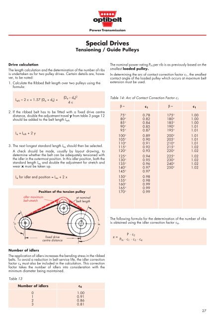
Special <strong>Drives</strong>Tensioning / Guide PulleysDrive calculationThe length calculation and the determination of the number of ribsis undertaken as <strong>for</strong> two pulley drives. Certain details are, however,to be noted:1. Calculate the <strong>Ribbed</strong> <strong>Belt</strong> length over two pulleys using the<strong>for</strong>mula:The nominal power rating P N per rib is as previously based on thesmallest loaded pulley.In determining the arc of contact correction factor c 1 , the smallestcontact angle of the loaded pulley which occurs at maximum beltextension must be used.L eth ≈ 2 c + 1.57 (D e + d e ) +2. If the ribbed belt has to be fitted with a fixed drive centredistance, double the adjustment travel y from table 3 page 12should be added to the belt length L ethL e = L eth + 2 y3. The next longest standard length L es should then be selected.A check should be made, usually by layout drawing, todetermine whether the belt can be adequately tensioned withthe idler in the outermost position. In this idler position, both thestandard length L es and double the adjustment <strong>for</strong> stretch andwear x must be taken up.L e <strong>for</strong> idler end position = L es + 2 xafter maximumbelt stretch(D e – d e ) 24 cPosition of the tension pulleyat nominalbelt lengthTable 14: Arc of Contact Correction Factor c 1β ≈75° 0.7880° 0.8285° 0.8490° 0.8595° 0.87100° 0.89105° 0.90110° 0.91115° 0.92120° 0.93125° 0.94130° 0.95135° 0.96140° 0.97145° 0.97150° 0.98155° 0.98160° 0.99165° 0.99170° 0.99c 1β ≈c 1175° 1.00180° 1.00185° 1.00190° 1.01195° 1.01200° 1.01205° 1.01210° 1.01215° 1.02220° 1.02225° 1.02230° 1.02240° 1.02250° 1.02The following <strong>for</strong>mula <strong>for</strong> the determination of the number of ribsis obtained using the idler correction factor c 4 .fixed drivecentre distancez =P · c 2P N · c 1 · c 3 · c 4Number of idlersThe application of idlers increases the bending stress in the ribbedbelts. To avoid a reduction in belt service life, the idler correctionfactor c 4 must also be included in the calculation. This correctionfactor takes the number of idlers into consideration with theminimum diameter being maintained.Table 13Number of idlers c 40 1.001 0.912 0.863 0.8127