Technical Manual for Ribbed Belt Drives
Technical Manual for Ribbed Belt Drives
Technical Manual for Ribbed Belt Drives
- No tags were found...

You also want an ePaper? Increase the reach of your titles
YUMPU automatically turns print PDFs into web optimized ePapers that Google loves.
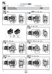
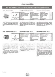
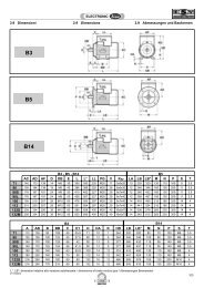
Design HintsOptikrik Tension Gauges 0, I, II, IIIThese tension gauges have been devised to simplify the maintenance of ribbed belt drives where the more essential technical data isunknown and the optimum tension cannot there<strong>for</strong>e be arrived at by calculation. With these simplified methods, all that is required isthe pulley diameter.Optikrik tension gauges - operating instructions -1. There are three ways of using the gauge (see illustration).2. The gauge is placed on the centre of the belt surface between the twopulleys. (First press the indicator arm down flush with the scale.)3. Place the gauge lightly on the belt and exert pressure slowly in themanner shown (A, B or C) using one finger only.4. Avoid touching the gauge with more than one finger whilst measuring.5. As soon as you hear or feel a click, immediately release the pressureand the indicator arm will remain in the measurement position.6. Carefully lift the gauge off, taking care not to displace the indicatorarm. The belt tension is indicated on the scale at the point where theupper edge of the indicator arm crosses the gauge body (see Fig.).7. To ensure an accurate reading, you can mark the measured point onthe scale with your thumb nail and then turn the gauge over to read it.8. Raise or lower the belt tension until it is within the required tensionrange.<strong>Belt</strong>SectioectionDiameteroffthesmallestpulleulleyd e( (mmmm)InitialInstallationstallationnRetensionInitialIInstallationstallationnStatic belt tension T max (N)RetensionInitialIInstallationstallationnRetensionInitialIInstallationstallationnRetensionInitialIInstallationstallationnRetensionPHPJPKPL4 PH8 PH12PH16PH20 PH≤ 25 90 70 150 130 250 200 300 250 400 300> 25 ≤ 71 110 90 200 150 300 250 350 300 450 350> 71 *4 PJ8 PJ12PJ16PJ24 PJ≤ 40 200 150 350 300 500 400 700 550 1000 800> 40 ≤ 80 200 150 400 350 600 500 800 650 1200 1000> 80 ≤ 132 250 200 450 350 700 550 900 700 1300 1000> 132 *4 PK8 PK10PK12PK16 PK≤ 63 300 250 600 450 700 600 900 700 1200 900> 63 ≤ 100 400 300 800 600 1000 700 1200 900 1500 1200> 100 ≤ 140 450 350 900 700 1100 800 1300 1000 1600 1300> 140 *6 PL8 PL10PL12PL16 PL≤ 90 800 600 1000 800 1300 1000 1500 1200 1900 1500> 90 ≤ 140 1000 700 1300 1000 1600 1300 1900 1500 2500 1900> 140 ≤ 200 1100 800 1400 1100 1900 1400 2100 1600 2800 2100> 200 *Method1. Locate the section in the left hand column.2. Select the smallest pulley diameter in the drive system.3. The table shows the corresponding static belt tension.4. Check the belt tension with the gauge as described.Example1. Optibelt-RB <strong>Ribbed</strong> <strong>Belt</strong> section 4 PJ2. Smallest pulley diameter in drive system d e 100 mm3. Static belt tension - initial fitting 250 N4. Static belt tension - retension 200 N44*Tension settings <strong>for</strong> these pulleys must be calculated.Tension gaugesOptikrik 0 Measurement range: 70 – 150 NOptikrik I Measurement range: 150 – 600 NOptikrik II Measurement range: 500 – 1400 NOptikrik III Measurement range: 1300 – 3100 NThe tension figures (static belt tension) are <strong>for</strong> guidance only whensufficient drive data is not available. They are based on themaximum transmissible power (per ribbed belt).Calculation basisPH, PJSpeed v = 5 bis 60 m/s.PKSpeed v = 5 bis 50 m/s.PLSpeed v = 5 bis 40 m/s.