OMP F1 - F2 (63) OMP P (63) OMP (63) - Plastorgomma
OMP F1 - F2 (63) OMP P (63) OMP (63) - Plastorgomma
OMP F1 - F2 (63) OMP P (63) OMP (63) - Plastorgomma

Create successful ePaper yourself
Turn your PDF publications into a flip-book with our unique Google optimized e-Paper software.
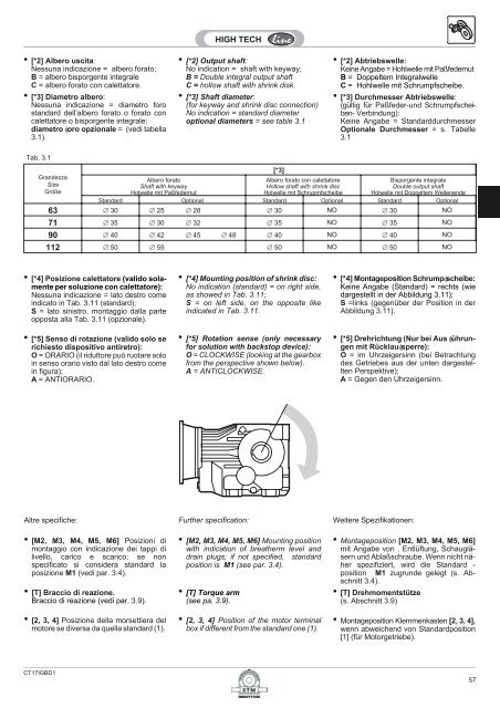
• [*2] Albero uscita:Nessuna indicazione = albero forato;B = albero bisporgente integraleC = albero forato con calettatore.• [*3] Diametro albero:Nessuna indicazione = diametro forostandard dell’albero forato o forato concalettatore o bisporgente integrale;diametro oro opzionale = (vedi tabella3.1).• [*2] Output shaft:No indication = shaft with keyway;B = Double integral output shaftC = hollow shaft with shrink disk.• [*3] Shaft diameter:(for keyway and shrink disc connection)No indication = standard diameteroptional diameters = see table 3.1• [*2] Abtriebswelle:Keine Angabe = Hohlwelle mit PaßfedernutB = Doppeltem IntegralwelleC = Hohlwelle mit Schrumpfscheibe.• [*3] Durchmesser Abtriebswelle:(gültig für Paßfeder-und Schrumpfscheiben-Verbindung):Keine Angabe = StandarddurchmesserOptionale Durchmesser = s. Tabelle3.1Tab. 3.1GrandezzaSizeGrößeAlbero foratoShaft with keywayHolwelle mit Paßfedernut[*3]Albero forato con calettatoreHollow shaft with shrink discHolwelle mit SchrupmfscheibeBisporgente integraleDouble output shaftHolwelle mit Doppeltem WellenendeStandard Optional Standard Optional Standard Optional<strong>63</strong> 30 25 28 30 NO 30 NO71 35 30 32 35 NO 35 NO90 40 42 45 48 40 NO 40 NO112 50 55 50 NO 50 NO• [*4] Posizione calettatore (valido solamenteper soluzione con calettatore):Nessuna indicazione = lato destro comeindicato in Tab. 3.11 (standard);S = lato sinistro, montaggio dalla parteopposta alla Tab. 3.11 (opzionale).• [*5] Senso di rotazione (valido solo serichiesto dispositivo antiretro):O = ORARIO (il riduttore può ruotare soloin senso orario visto dal lato destro comein figura);A = ANTIORARIO.• [*4] Mounting position of shrink disc:No indication (standard) = on right side,as showed in Tab. 3.11;S = on left side, on the opposite likeindicated in Tab. 3.11.• [*5] Rotation sense (only necessaryfor solution with backstop device):O = CLOCKWISE (looking at the gearboxfrom the perspective shown below).A = ANTICLOCKWISE.• [*4] Montageposition Schrumpscheibe:Keine Angabe (Standard) = rechts (wiedargestellt in der Abbildung 3.11);S =links (gegenüber der Position in derAbbildung 3.11).• [*5] Drehrichtung (Nur bei Aus ührungenmit Rücklausperre):O = im Uhrzeigersinn (bei Betrachtungdes Getriebes aus der unten dargestelltenPerspektive);A = Gegen den Uhrzeigersinn.Altre specifiche: Further specification: Weitere Spezifikationen:• [M2, M3, M4, M5, M6] Posizioni dimontaggio con indicazione dei tappi dilivello, carico e scarico; se nonspecificato si considera standard laposizione M1 (vedi par. 3.4).• [T] Braccio di reazione.Braccio di reazione (vedi par. 3.9).• [2, 3, 4] Posizione della morsettiera delmotore se diversa da quella standard (1).• [M2, M3, M4, M5, M6] Mounting positionwith indication of breatherm level anddrain plugs; if not specified, standardposition is M1 (see par. 3.4).• [T] Torque arm(see pa. 3.9).• [2, 3, 4] Position of the motor terminalbox if different from the standard one (1).• Montageposition [M2, M3, M4, M5, M6]mit Angabe von . Entlüftung, Schaugläsernund Ablaßschraube. Wenn nicht näherspezifiziert, wird die Standard -position M1 zugrunde gelegt (s. Abschnitt3.4).• [T] Drehmomentstütze(s. Abschnitt 3.9)• Montageposition Klemmenkasten [2, 3, 4],wenn abweichend von Standardposition[1] (für Motorgetriebe).CT17IGBD157