OMP F1 - F2 (63) OMP P (63) OMP (63) - Plastorgomma
OMP F1 - F2 (63) OMP P (63) OMP (63) - Plastorgomma
OMP F1 - F2 (63) OMP P (63) OMP (63) - Plastorgomma

You also want an ePaper? Increase the reach of your titles
YUMPU automatically turns print PDFs into web optimized ePapers that Google loves.
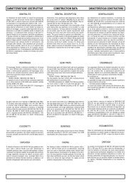
3.1 Caratteristiche tecnicheLa progettazione di questi riduttori è stataimpostata su una struttura monolitica particolarmenterigida che permette l’applicazione dielevati carichi.Carcasse e flange sono realizzate in ghisa meccanicaGG200 - GG250 ISO 185 ad eccezionedei tipi grandezza <strong>63</strong> e 71 realizzati in alluminioSG-AlSi UNI 1706.La lavorazione di tutte le carcasse avviene sumoderni centri di lavoro a controllo numerico chepermette di ottenere la massima precisionecostruttiva.L’albero di entrata è realizzato in acciaio39NiCrMo3 UNI EN 10083 bonificato; quello inuscita in acciaio C40 UNI 5332. Tutti gliingranaggi sono realizzati in acciaio 18NiCrMo5UNI 7846 cementati, temprati e rettificati permigliorarne il rendimento e la silenziosità anchesotto carico.3.1 Technical characteristicsThe design of this series of gearboxes has beenset up on a very rigid monolithic structureenabling the application of heavy loads.Housings and flanges are manufactured inengineering cast iron GG200 - GG250 ISO 185,except for size <strong>63</strong> and 71, made of aluminiumSG-AlSi UNI 1706.All the housings working takes place in numericalcontrol working centres, that ensure themaximum constructive accuracy.The input shaft is made spring tempered steel39NiCrMo3 UNI EN 10083; the output shaft ismade of steel C40 UNI 5332. All gears are madeof steel 18NiCrMo5 UNI 7846, previouslycasehardened, hardened and rectified toimprove efficiency and quietness even underload.3.1 Technische EigenschaftenDer Entwicklung dieser Getriebeserie wurde einemonolithische Gehäusestruktur zugrundegelegt.Mit Ausnahme der Modelle <strong>63</strong> und 71, bei denenaufgrund der kleinen Baugröße Aluminium SG-AISi UNI 1706 verwendet wird, sind alle Gehäuseund Flansche aus Maschinenguß GG200 -GG250 ISO 185.Die Bearbeitung der Gehäuse erfolgt aufmodernsten, numerisch gesteuerten Fertigungsmaschinen,wodurch eine hohe Fertigungsgenauigkeitund-qualität erzielt wird. DieAntriebswelle besteht aus einsatzgehärtetem undvergütetem 39NiCrMo3 Stahl UNI EN 10083, dieAbtriebswelle aus C40 Stahl UNI 5332. AlleZahnräder sind aus 18NiCrMo5 Stahl UNI 7846,gehärtet, einsatzgehärtet und geschliffen.Dies ermöglicht einen hohen Wirkung-sgradsowie einen geräuscharmen Lauf auch unter Last.Alle Kegelradgetriebe und-Getriebemotorenbesitzen drei Unterse- tzungsstufen.3.2 Designazione 3.2 Designation3.2 BezeichnungDesignazione riduttoriGearboxes designationBezeichnung GetriebesOM - OR - OCVersioneVersionAusführungGrand.SizeGrößeTipoTypeTyp* 1 * 2 * 3 *4 *5 ir IECTipoTypeTypGrandezzaSizeGrößeLunghezzaLenghtLängeDesignazione MotoriDesignation MotorsBezeichnung Motoren13180 (B5)80 (B14)....Esempio / ExampleBeispiel<strong>OMP</strong> 71 C 1:37.080 B5OMORSieheLeistungstabellenP**<strong>63</strong>-71-90-112F71-90-112<strong>63</strong>7190112—<strong>F1</strong><strong>F2</strong>P—S—BCDiametroforoopzionaleOptionalhollow shaftdiameterOptionalerHohlwellendurchmesser—SOAVeditabelleprestazioniSeeperformancetablesTTA....H56....315A....ML<strong>OMP</strong> 90 1: 92.3T 56 A 4 B5ORP <strong>63</strong> P SC1:27.4OC59 59TTA....H56....315A....MLOCP 112 C 1:57.1T 56 A 4** La versione P può montare le flange <strong>F1</strong>, <strong>F2</strong>, P solonella grandezza <strong>63</strong>** Version P may be fitted with flanges <strong>F1</strong>, <strong>F2</strong> and P onlyis size <strong>63</strong>.** Auf der Version P können die Flansche <strong>F1</strong>, <strong>F2</strong>, P nurin der Baugröße <strong>63</strong> montiert werden.Specifiche: Specification: Spezifikationen:]• [*1] Lato flangia uscita:Nessuna indicazione = flangia uscita conmontaggio destro (flange dal lato comeindicato nelle figure del catalogo);S = flange uscita con montaggio sinistro(flange dal lato opposto alle figureindicate a catalogo).• [*1] Mounting position output side:No indication (standard) = output flangeon right side (like indicated in the figures);S = output flange on left side (flanges onthe opposite side like indicated infigures).• [*1] Montageseite Abtriebsflansch:Keine Angabe (Standard) = Abtriebsflanschrechts (wie in den Abbildungendargestellt)S = Abtriebsflansch links (gegenüber derPosition in den Katalogabbildungen).56CT17IGBD1