SM 25 - Plastorgomma
SM 25 - Plastorgomma
SM 25 - Plastorgomma

Create successful ePaper yourself
Turn your PDF publications into a flip-book with our unique Google optimized e-Paper software.
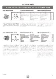
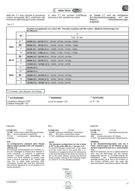
Nella tab. 2.7 sono riportate le grandezze<br />
motore accoppiabili (IEC) unitamente alle<br />
dimensioni albero/flangia motore standard.<br />
Tab. 2.7<br />
In table 2.7 the possible shaft/flange<br />
dimensions IEC standard are listed.<br />
IIn Tabelle 2.7 sind die verfügbaren<br />
IEC-Standardmotoreingänge mit den<br />
Wellen-u. Flanschabmessungen<br />
aufgelistet.<br />
IEC<br />
Possibili accoppiamenti con motori IEC - Possible couplings with IEC motors - Mögliche Verbindungen mit<br />
IEC-Motoren<br />
ir<br />
Tutti / All / Alle<br />
90 (2) 24/200 (B5) - 24/140 (B14) 24/160 - 24/120 - 24/105 - 24/90<br />
<strong>SM</strong><strong>25</strong><br />
80 (1) 19/200 (B5) - 19/120 (B14) 19/160 - 19/140 - 19/105 - 19/90<br />
71 14/160 (B5) - 14/105• (B14) 14/200 - 14/140 - 14/120 - 14/90<br />
63 11/140 (B5) - 11/90 (B14) - 11/200 - 11/160 - 11/120 - 11/105<br />
90 (1) 24/200 (B5) - 24/140 (B14) 24/160 - 24/120 - 24/105<br />
<strong>SM</strong> 35<br />
80 19/200 (B5) - 19/120 (B14) 19/160 - 19/140 - 19/105<br />
71 14/160 (B5) - 14/105• (B14) 14/200 - 14/140 - 14/120<br />
112 (2) 28/160 (B14)<br />
100 (2) 28/160 (B14)<br />
<strong>SM</strong>45<br />
90 (1) 24/200 (B5) - 24/140 (B14) 24/160 - 24/120 - 24/105<br />
80 19/200 (B5) - 19/120 (B14) 19/160 - 19/140 - 19/105<br />
71 14/160 (B5) - 14/105• (B14) 14/200 - 14/140 - 14/120<br />
(2) A richiesta / Upon Request / Auf Anfrage<br />
(1) ATTENZIONE!<br />
(1) WARNING!<br />
(1) ACHTUNG!<br />
Linguette a disegno STM.<br />
(Vedere Paragrafo 1.9).<br />
(Look at chapter 1.9). (s. S. 1.9).<br />
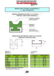
Legenda:<br />
11/140 (B5) 11/120<br />
11/140 : combinazioni albero/flangia standard<br />
(B5) : forma costruttiva motore IEC<br />
11/120 : combinazioni albero/flangia a<br />
richiesta<br />
N.B.<br />
La configurazione standard della flangia<br />
attacco motore prevede 4 fori a 45° (esempio x:<br />
vedi par. 2.3).<br />
Per le flange contrassegnate con il simbolo (•) i<br />
fori per il fissaggio al motore sono disposti in<br />
croce (esempio +). Pertanto è opportuno<br />
valutare l’ingombro della morsettiera del<br />
motore che verrà installato in quanto essa<br />
verrà a trovarsi orientata a 45° rispetto agli<br />
assi. Per la scelta della posizione della<br />
morsettiera rispetto agli assi fare riferimento<br />
allo schema seguente (in cui la posizione 5 è<br />
quella standard):<br />
Key:<br />
11/140 (B5) 11/120<br />
11/140 : standard shaft/flange combination<br />
(B5) : IEC motor constructive shape<br />
11/120 : shaft/flange combinations upon request<br />
NOTE.<br />
The standard configuration for the 4 holes<br />
is 45° to the axles (like an x: see par. 2.3).<br />
For the B14 flanges marked with (•) the holes<br />
to fit the motor are on the axles (like a +).<br />
Therefore we suggest to check the dimensions<br />
of the terminal board of the motor as it will be at<br />
45° to the axles. Please, choose the terminal<br />
board position refering to the following sketch<br />
(in which N° 5 is the standard position):<br />
Legende:<br />
11/140 (B5) 11/120<br />
11/140 : Standardkombinationen<br />
Welle/Flansch<br />
(B5) : Konstruktionsform IEC-Motor<br />
11/120 : Sonderkombinationen Welle/Flansch<br />
HINWEIS.<br />
In der Standardkonfiguration sind die 4<br />
Flans- chbohrungen im 45°-Winkel zu den<br />
Achsen angeordnet (wie ein x: siehe Kapital<br />
2.3).<br />
Bei B14-Flanschen, die mit (•) gekennzeichnet<br />
sind, sind die Bohrungen auf den Achsen<br />
angeordnet (wie ein +). Es sollte deshalb der<br />
Platzbedarf des Motorklemmenkastens<br />
beachtet werden, da er sich in 45°-Position zu<br />
den Achsen befinden wird. Die Lage des<br />
Klemmenkastens des Motors wählen Sie bitte<br />
CT22IGBD3<br />
21