Serieâ EL60/ELT60 - Alvit.it
Serieâ EL60/ELT60 - Alvit.it
Serieâ EL60/ELT60 - Alvit.it

You also want an ePaper? Increase the reach of your titles
YUMPU automatically turns print PDFs into web optimized ePapers that Google loves.
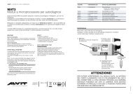
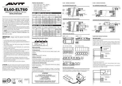
<strong>EL60</strong>-<strong>ELT60</strong><br />
emergency lighting k<strong>it</strong> for led:<br />
installation guide<br />
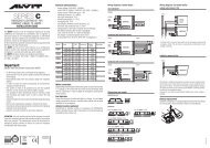
Technical characteristics:<br />
– supply voltage: 220÷240V - 50/60Hz<br />
– supply current: 20mA - cos 0.6<br />
– max case temperature: 70°C<br />
– ambient temperature: 5÷50°C<br />
– recharging time: 24h<br />
– terminals max connection size: 1.5mm 2<br />
<strong>EL60</strong>71 - <strong>ELT60</strong>71 - 1h - Batt. 7,2V-1,6Ah<br />
Dip-sw<strong>it</strong>ch Emergency Emergency Max power LED Max<br />
pos<strong>it</strong>ion working voltage (VL) output current (I) current controlled LED modules<br />
voltage controlled<br />
A 9 - 12V 350mA N LED =12 / V F 24W<br />
B 9 - 24V 350-250mA N LED =24 / V F 30W<br />
C 9 - 46V 350-100mA N LED =46 / V F -<br />
D 9 - 58V 350-85mA N LED =58 / V F -<br />
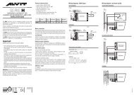
<strong>EL60</strong> - Wiring diagrams<br />
non-maintained (emergency only)<br />
<strong>ELT60</strong> - Wiring diagrams<br />
non-maintained (emergency only)<br />
The electronic un<strong>it</strong>s for emergency lighting are su<strong>it</strong>able for power<br />
LED (current controlled) or LED modules (voltage controlled).<br />
They can be used indifferently for maintained (main, 220/240V, in<br />
combination w<strong>it</strong>h LED electronic driver), or emergency operation.<br />
All the models have sealed Ni-Cd batteries able to guarantee high<br />
efficiency w<strong>it</strong>h high temperatures.<br />
The ALVIT can be put on a false ceiling or an a ceiling lamp, module,<br />
channel, thus allowing any light spot to be qualified for emergency<br />
in a simple and quick way, where needed.<br />
The ALVIT electronic devices are designed according to EN61347-<br />
2-13, EN61347-2-7, EN61547, EN55015, EN60598-2-22,<br />
EN61000-3-2, SELV.<br />
Important: always read the present instruction<br />
leaflet<br />
<strong>EL60</strong>74/3 - <strong>ELT60</strong>74/3 - 3h - Batt. 7,2V-4Ah<br />
Dip-sw<strong>it</strong>ch Emergency Emergency Max power LED Max<br />
pos<strong>it</strong>ion working voltage (VL) output current (I) current controlled LED modules<br />
voltage controlled<br />
A 9 - 12V 350mA N LED =12 / V F 24W<br />
B 9 - 24V 350-250mA N LED =24 / V F 30W<br />
C 9 - 46V 350-100mA N LED =46 / V F -<br />
D 9 - 58V 350-85mA N LED =58 / V F -<br />
Emergency Vmax dip-sw<strong>it</strong>ch settings<br />
26<br />
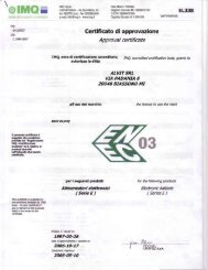
maintained w<strong>it</strong>h external electronic driver<br />
Dimension and weigth<br />
<strong>EL60</strong> - 0,13Kg<br />
<strong>ELT60</strong> - 0,13Kg<br />
maintained w<strong>it</strong>h external electronic driver<br />
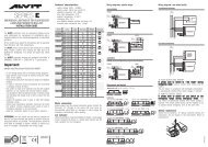
inhib<strong>it</strong>ions Wiring diagrams<br />
Rest mode facil<strong>it</strong>y<br />
– for the wiring please refer to enclosed wiring diagrams<br />
– great attention must be paid to polar<strong>it</strong>y during the installation of<br />
the battery<br />
– keep batteries away from heat sources (away from electronic<br />
driver or LED source)<br />
– in order to check the correct functional<strong>it</strong>y we recommend a<br />
charging of about 30 hours<br />
– this system is made to be powered only w<strong>it</strong>h the supplied batteries:<br />
do not connect any external battery charger.<br />
– <strong>it</strong> is advisable to effect periodically (every 3 months) at least one<br />
discharge and charge cycle in order to assure the max efficiency<br />
– replace the batteries every 4 years or after 500 charge/discharge<br />
cycles<br />
– before every maintenance operation, disconnect all mains<br />
– this product contains materials which could be toxic if improperly<br />
disposed in the environment<br />
– keep this instruction leaflet for any further reference<br />
ATTENTION: this un<strong>it</strong> should only be used for purposes for which<br />
<strong>it</strong> has been intended and should be installed using the instructions<br />
which are provided. The manufacturer cannot be held liable for<br />
damages to person, animals or objects as a result of improper,<br />
unreasonable and wrong usage.<br />
A B C D<br />
12V 24V 45V 57V<br />
1 ON - ON -<br />
2 ON ON - -<br />
Mains connection:<br />
please always read the present instruction guide.<br />
1) Led source out:<br />
Connect LED source to the OUT terminal (always respect cable<br />
polar<strong>it</strong>y).<br />
2) Battery:<br />
Connect battery to BATT. terminal.<br />
3) Mains connection:<br />
Connect the terminals 1 - 2 (L - N) to the mains that must never be<br />
disconnected (battery charge). When there is a decrease in mains<br />
voltage the emergency automatically starts working.<br />
4) External driver LED connection:<br />
Connect the terminal + and - to appropriate external driver (always<br />
respect cable polar<strong>it</strong>y).<br />
Led indicator:<br />
Shows the presence of mains and battery in charge. It must always<br />
remain connected to device in a visible place outside near the lamp<br />
qualified for the emergency.<br />
51<br />
155<br />
1h - 7,2V-1,6Ah | 0,30 Kg<br />
1h - 7,2V-1,6Ah | 0,30 Kg<br />
3h - 7,2V-4Ah | 0,75 Kg<br />
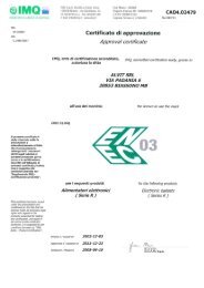
battery replacement<br />
3h - 7,2V-4Ah | 0,75 Kg<br />
Sealed Ni-Cd batteries. To replace batteries follows the instructions.<br />
Do not discard in the environment. Return to manufacturer.<br />
remote control device<br />
<strong>it</strong> allows both to sw<strong>it</strong>ch off and sw<strong>it</strong>ch on the emergency lamps during<br />
emergency mode. The rest mode is automatically resetted when mains<br />
voltage is restored. This remote control device can be installed so as to<br />
operate several emergency un<strong>it</strong>s at the same time.<br />
3<br />
4<br />
TELECOMANDO<br />
INIBIZIONE<br />
EMERGENCY<br />
+<br />
- REST<br />
MODE<br />
push button and battery<br />
<strong>it</strong> allows only to sw<strong>it</strong>ch to “rest mode” during emergency mode, using a<br />
remote push button and 9V battery.<br />
The rest mode, in accordance w<strong>it</strong>h Standards prescriptions, is automatically<br />
resetted when mains voltage is restored.<br />
ATTENTION!<br />
to not cause led damage,<br />
please connect following this order:<br />
1) led source;<br />
2) battery cable;<br />
3) mains connection<br />
do not disconnect and connect the led<br />
source during emergency operation<br />
ISO 9001: 2008<br />
Made in Italy<br />
www.alv<strong>it</strong>.<strong>it</strong><br />
info@alv<strong>it</strong>.<strong>it</strong><br />
3<br />
4<br />
EMERGENCY<br />
+<br />
- REST<br />
MODE<br />
R02-05.12
<strong>EL60</strong>-<strong>ELT60</strong><br />
K<strong>it</strong> d'emergenza per LED:<br />
guida all'installazione<br />
Caratteristiche Tecniche:<br />
– tensione di alimentazione: 220÷240V - 50/60Hz<br />
– corrente di alimentazione: 20mA - cos 0.6<br />
– temperatura max d’esercizio misurata sull’involucro: 70°C<br />
– temperatura ambiente: 5÷50°C<br />
– tempo di ricarica: 24 h<br />
– portata morsettiera: 1.5mm 2<br />
<strong>EL60</strong>71 - <strong>ELT60</strong>71 - 1h - Batt. 7,2V-1,6Ah<br />
Posizione Tensione di lavoro Corrente di usc<strong>it</strong>a Numero max Potenza max<br />
Dip-sw<strong>it</strong>ch in emergenza (VL) in emergenza (I) Power LED per moduli LED<br />
in corrente in tensione<br />
A 9 - 12V 350mA N LED =12 / V F 24W<br />
B 9 - 24V 350-250mA N LED =24 / V F 30W<br />
C 9 - 46V 350-100mA N LED =46 / V F -<br />
D 9 - 58V 350-85mA N LED =58 / V F -<br />
<strong>EL60</strong> - Schemi di collegamento<br />
Non permanente (solo emergenza)<br />
<strong>ELT60</strong> - Schemi di collegamento<br />
Non permanente (solo emergenza)<br />
Gli alimentatori elettronici per illuminazione d’emergenza a funzionamento<br />
interm<strong>it</strong>tente ALVIT sono predisposti per alimentare<br />
LED di potenza (controllati in corrente) o moduli led (controllati in<br />
tensione) con la normale tensione di rete (220-240V - 50/60Hz),<br />
possono essere collegati per funzionamento permanente o non<br />
permanente, con qualsiasi tipo di alimentatore elettronico per LED.<br />
Tutti i modelli sono dotati di accumulatori ermetici al Ni-Cd in<br />
grado di garantire elevati rendimenti anche con alte temperature.<br />
Gli ALVIT possono essere inser<strong>it</strong>i all’interno di plafoniere, moduli<br />
o canaline, consentendo così di abil<strong>it</strong>are all’emergenza, in modo<br />
semplice e rapido, qualsiasi punto luce nel posto in cui serve.<br />
Gli apparecchi elettronici ALVIT sono costru<strong>it</strong>i in conform<strong>it</strong>à alle<br />
norme EN61347-2-13, EN61347-2-7, EN61547, EN55015,<br />
EN60598-2-22, EN61000-3-2, SELV<br />
Avvertenze: leggere attentamente il contenuto del<br />
presente foglio di istruzioni<br />
– eseguire i collegamenti dell’alimentatore secondo gli schemi<br />
qui riportati<br />
– collegare la batteria all’alimentatore prestando molta attenzione<br />
alla polar<strong>it</strong>à del connettore<br />
– posizionare la batteria il più lontano possibile da fonti di calore<br />
(in modo particolare non a ridosso dell’alimentatore elettronico<br />
o della piastra LED)<br />
– la batteria, ad installazione ultimata, deve essere ricaricata per<br />
almeno 30 ore affinchè il sistema sia in grado di funzionare con<br />
l’autonomia dichiarata<br />
– il sistema deve essere alimentato unicamente con la batteria in<br />
dotazione, non associare a dispos<strong>it</strong>ivi di ricarica esterni<br />
– effettuare periodicamente (ogni tre mesi) almeno un ciclo di<br />
scarica e ricarica della batteria per ottenere la massima efficienza<br />
del sistema<br />
– sost<strong>it</strong>uire le batterie ogni 4 anni o dopo circa 500 cicli di scarica<br />
e ricarica<br />
– prima di ogni operazione di manutenzione disinserire tutte le<br />
alimentazioni, compresa la batteria<br />
– non disperdere nell’ambiente i materiali contenuti nel<br />
prodotto<br />
– conservare il presente foglio di istruzioni per ogni ulteriore<br />
consultazione<br />
ATTENZIONE: questo sistema è destinato esclusivamente all’uso per il quale<br />
è stato progettato e realizzato. L’installazione deve essere esegu<strong>it</strong>a seguendo<br />
le istruzioni forn<strong>it</strong>e nel presente prospetto. Ogni altro impiego è da considerarsi<br />
improprio e quindi pericoloso; ALVIT declina ogni responsabil<strong>it</strong>à per<br />
eventuali danni a persone, animali o cose da imputarsi a quanto sopra c<strong>it</strong>ato.<br />
ISO 9001: 2008<br />
Made in Italy<br />
www.alv<strong>it</strong>.<strong>it</strong><br />
info@alv<strong>it</strong>.<strong>it</strong><br />
<strong>EL60</strong>74/3 - <strong>ELT60</strong>74/3 - 3h - Batt. 7,2V-4Ah<br />
Posizione Tensione di lavoro Corrente di usc<strong>it</strong>a Numero max Potenza max<br />
Dip-sw<strong>it</strong>ch in emergenza (V L ) in emergenza (I) Power LED per moduli LED<br />
in corrente in tensione<br />
A 9 - 12V 350mA N LED =12 / V F 24W<br />
B 9 - 24V 350-250mA N LED =24 / V F 30W<br />
C 9 - 46V 350-100mA N LED =46 / V F -<br />
D 9 - 58V 350-85mA N LED =58 / V F -<br />
Impostazioni dip-sw<strong>it</strong>ch Vmax in emergenza<br />
A B C D<br />
12V 24V 45V 57V<br />
1 ON - ON -<br />
2 ON ON - -<br />
COLLEGAMENTI<br />
1) Usc<strong>it</strong>a alimentazione sorgente Led:<br />
collegare la sorgente LED al morsetto OUT, rispettando la polar<strong>it</strong>à.<br />
2) Batteria:<br />
collegare la batteria al morsetto BATT.<br />
3) Collegamento alla rete:<br />
Collegare i morsetti 1 - 2 (L - N) alla rete che non deve essere mai<br />
interrotta (circu<strong>it</strong>o di ricarica della batteria).<br />
Al mancare o all’abbassarsi dell’alimentazione di rete, automaticamente<br />
entra in funzione l’emergenza.<br />
4) Collegamento ad un driver LED:<br />
Collegare i morsetti + e - ai relativi morsetti di usc<strong>it</strong>a di un appropriato<br />
driver esterno (rispettare la polar<strong>it</strong>à).<br />
Led spia (indicatore):<br />
segnala presenza di rete e batterie in carica. Deve rimanere<br />
sempre collegato all’apparecchio ed è opportuno collocarlo in<br />
modo visibile all’esterno.<br />
ATTENZIONE!<br />
per non danneggiare i led collegare nell'ordine:<br />
1) sorgente led;<br />
2) cavo batteria;<br />
3) alimentazione di rete<br />
non scollegare e ricollegare i led<br />
con emergenza in funzione<br />
26<br />
51<br />
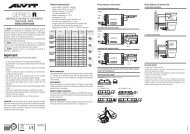
Permanente (illuminazione ordinaria)<br />
Dimensioni e peso<br />
<strong>EL60</strong> - 0,13Kg<br />
155<br />
1h - 7,2V-1,6Ah | 0,30 Kg<br />
1h - 7,2V-1,6Ah | 0,30 Kg<br />
3h - 7,2V-4Ah | 0,75 Kg<br />
sost<strong>it</strong>uzione della batteria<br />
<strong>ELT60</strong> - 0,13Kg<br />
3h - 7,2V-4Ah | 0,75 Kg<br />
Batterie ermetiche al Ni-Cd. Per la sost<strong>it</strong>uzione estrarre il connettore<br />
come indicato in figura. Non disperdere nell'ambiente. Rendere<br />
al produttore.<br />
Permanente (illuminazione ordinaria)<br />
Schemi di collegamento per inibizione<br />
Modo Riposo<br />
con telecomando esterno centralizzato<br />
Permette sia lo spegnimento che la riaccensione delle lampade durante il<br />
funzionamento in emergenza. Al rientro della tensione di rete il sistema si<br />
predisporrà ad un nuovo intervento in emergenza.<br />
3<br />
4<br />
TELECOMANDO<br />
INIBIZIONE<br />
EMERGENCY<br />
+<br />
- REST<br />
MODE<br />
con pulsante e batteria<br />
Permette il solo spegnimento delle lampade durante il funzionamento in<br />
emergenza. L’inibizione viene attivata agendo su di un pulsante collegato<br />
ad una batteria a 9 V.<br />
Al rientro della tensione di rete il sistema si predisporrà ad un nuovo intervento<br />
in emergenza eliminando il rischio di non ripristino del sistema.<br />
3<br />
4<br />
EMERGENCY<br />
+<br />
- REST<br />
MODE<br />
R02-05.12