T 521 SNC-OPT CE_04 ITA-UK.pmd
T 521 SNC-OPT CE_04 ITA-UK.pmd
T 521 SNC-OPT CE_04 ITA-UK.pmd

You also want an ePaper? Increase the reach of your titles
YUMPU automatically turns print PDFs into web optimized ePapers that Google loves.
T <strong>521</strong> <strong>SNC</strong> - <strong>OPT</strong><br />
<strong>ITA</strong><br />
MANUALE D’USO E<br />
MANUTENZIONE<br />
Conservarlo in luogo sicuro<br />
e accessibile per la consultazione<br />
<strong>UK</strong><br />
OPERATION AND MAINTENAN<strong>CE</strong><br />
MANUAL<br />
Keep in a safe and accesible place<br />
for future reference<br />
MATRICOLA MACCHINA:<br />
ANNO DI COSTRUZIONE:<br />
CODI<strong>CE</strong> MANUALE <strong>SNC</strong>:<br />
CODI<strong>CE</strong> MANUALE <strong>OPT</strong>:<br />
DATA DI REDAZIONE:<br />
REDATTORE:<br />
VERIFICATO da:<br />
29-10-93152*-<strong>04</strong>_<strong>04</strong><br />
29-10-93152*-<strong>04</strong>_<strong>04</strong><br />
Settembre 2006<br />
Ivano Pongiluppi<br />
Alfredo Frosi<br />
OMGA S.p.A. - Via Carpi-Ravarino n. 146<br />
41010 LIMIDI di Soliera (Modena) - Italia<br />
Tel. 0039.059.897333 - Fax 0039.059.565000<br />
E-Mail: omga@omga.it
INDI<strong>CE</strong> GENERALE<br />
PAGE<br />
GENERAL INDEX<br />
Indice<br />
Vocabolario grafico<br />
Informazioni generali<br />
Informazioni generali - Leggere attentamente<br />
Norme di sicurezza<br />
Identificazione della macchina<br />
Caratteristiche tecniche<br />
Equipaggiamenti possibili<br />
Modalità di movimentazione e di sollevamento<br />
Punti di appoggio - livellamento e fissaggio<br />
Ingombri e peso<br />
Come collegare FP alla T <strong>521</strong><br />
Marcatura di sicurezza<br />
Dispositivi di sicurezza<br />
Collegamento elettrico<br />
Collegamento pneumatico<br />
Collegamento aspirazione<br />
Rilevazione del rumore emesso<br />
Capacità di taglio<br />
Uso previsto della macchina<br />
Comandi<br />
Comandi e dispositivi di lavoro<br />
Ciclo di lavoro<br />
Capacità di trasporto delle Pinze<br />
Ambiene di lavoro<br />
Regole per la manutenzione ordinaria e straordinaria<br />
Note<br />
Manutenzione ordinaria<br />
Sostituzione lama<br />
Lubrificazione (ingrassaggio)<br />
Proiettore laser<br />
Alcuni Optionals<br />
Optionals - T <strong>521</strong> <strong>SNC</strong> / <strong>OPT</strong><br />
Note<br />
2÷3<br />
4<br />
5<br />
6÷7<br />
8÷9<br />
10<br />
11<br />
12÷13<br />
13÷16<br />
16÷17<br />
18<br />
19<br />
20÷21<br />
21÷26<br />
26÷27<br />
27÷28<br />
29<br />
30<br />
31<br />
31÷32<br />
32÷34<br />
35÷37<br />
37÷44<br />
44÷45<br />
45<br />
46<br />
47<br />
48<br />
49÷51<br />
51÷52<br />
53<br />
54<br />
55÷58<br />
59<br />
Index<br />
Key to graphic symbols<br />
General informations<br />
General informations - Read carefully<br />
Safety rules<br />
Machine identification<br />
Technical specifications<br />
Available machine configurations<br />
Handling and lifting means<br />
Support points - levelling and fixing<br />
Total dimensions and weight<br />
How to connect the FP to the T <strong>521</strong> saw<br />
Safety marking<br />
Safety devices<br />
Wiring<br />
Pneumatic connections<br />
Dust extraction connections<br />
Measuring sound emissions<br />
Cutting capacity<br />
Prescribed machine uses<br />
Controls<br />
Controls and operating devices<br />
Work cycle<br />
Gripper transfer capacity<br />
Work environment<br />
Rules for routine and special maintenance<br />
Notes<br />
Routine maintenance<br />
Blade replacement<br />
Lubrication (greasing)<br />
Laser projector<br />
Some optional equipment<br />
Optional equipment - T <strong>521</strong> <strong>SNC</strong> / <strong>OPT</strong> saw<br />
Notes<br />
T <strong>521</strong> <strong>OPT</strong> <strong>CE</strong> 6000 = CODE: 29-10-931526-<strong>04</strong>_<strong>04</strong><br />
T <strong>521</strong> <strong>OPT</strong> <strong>CE</strong> 4000 = CODE: 29-10-931524-<strong>04</strong>_<strong>04</strong><br />
T <strong>521</strong> <strong>SNC</strong> <strong>CE</strong> 6000 = CODE: 29-10-931523-<strong>04</strong>_<strong>04</strong><br />
T <strong>521</strong> <strong>SNC</strong> <strong>CE</strong> 4000 = CODE: 29-10-931522-<strong>04</strong>_<strong>04</strong><br />
2 T <strong>521</strong> <strong>SNC</strong> / <strong>OPT</strong>
INDI<strong>CE</strong> GENERALE<br />
PAGE<br />
GENERAL INDEX<br />
T <strong>521</strong> <strong>SNC</strong> / <strong>OPT</strong><br />
3
VOCABOLARIO GRAFICO<br />
SYMB<br />
KEY TO GRAPHIC SYMBOLS<br />
4 T <strong>521</strong> <strong>SNC</strong> / <strong>OPT</strong>
INFORMAZIONI GENERALI<br />
GENERAL INFORMATIONS<br />
La OMGA S.p.A. non potrà essere ritenuta responsabile degli<br />
eventuali danni che risulteranno da un utilizzo non descritto in questo<br />
manuale o da una manutenzione effettuata non correttamente.<br />
Tutti i diritti sono riservati alla OMGA S.p.A.<br />
Tutti i dati, descrizioni ed illustrazioni del presente manuale, non<br />
sono impegnativi. La OMGA S.p.A. si riserva il diritto di apportare,<br />
senza preavviso, tutte le modifiche che riterrà opportune, per<br />
esigenze tecniche o migliorative.<br />
Per qualsiasi necessità o consiglio d’uso, rivolgetevi al<br />
Concessionario di zona.<br />
GARANZIA<br />
La macchina è garantita per un periodo di 12 mesi, a partire dalla<br />
data della fattura d’acquisto.<br />
Essa consiste nella sostituzione gratuita di tutte le parti meccaniche<br />
che presentino difetto di materiale o di fabbricazione.Sono esenti<br />
da garanzia, tutti i componenti elettrici ed elettronici. Inoltre, non<br />
sono coperti i guasti o i difetti dovuti a fattori esterni, errori di<br />
manutenzione, utilizzo improprio della macchina, uso della stessa<br />
in condizioni di sovraccarico, usura naturale, errori di montaggio o<br />
altre cause non imputabili al costruttore.<br />
La spedizione in sostituzione, è intesa franco nostro stabilimento.<br />
La macchina resa, anche se in garanzia, dovrà essere spedita in porto<br />
franco.<br />
Per avvalersi del diritto di garanzia nei confronti dell’ OMGA S.p.A.<br />
è necessario fornire le seguenti informazioni:<br />
• Modello della macchina<br />
• N° di matricola<br />
• Tensione e frequenza della macchina<br />
• Nominativo del Concessionario presso il quale è stata acquistata<br />
• Descrizione dell’eventuale difetto riscontrato<br />
• Descrizione del tipo di lavorazione eseguita<br />
• Ore di utilizzo giornaliere<br />
In mancanza dei sopracitati dati anche in maniera parziale non sarà<br />
possibile dare corso alla procedura di eventuale garanzia.<br />
Inviare a:<br />
OMGA S.p.A.<br />
Via Carpi-Ravarino N. 146<br />
41010 Limidi di Soliera<br />
(Modena) Italy<br />
La macchina è stata costruita nel rispetto dei requisiti essenziali di<br />
sicurezza espressi nella Direttiva 98/37/<strong>CE</strong>. La sostituzione di pezzi<br />
deve pertanto essere effettuata solo con pezzi adeguati richiesti a<br />
OMGA S.p.A.<br />
È proibito l’impiego di pezzi simili non forniti direttamente da<br />
OMGA S.p.A.<br />
Utilizzare pezzi simili, non forniti da OMGA S.p.A., o non seguire<br />
le indicazioni contenute in questo manuale fa cessare<br />
automaticamente la responsabilità di OMGA S.p.A.<br />
Tutte le nostre macchine subiscono in stabilimento un collaudo.<br />
Eventuali danni riscontrati al momento del disimballo devono essere<br />
notificati immediatamente al vettore.<br />
Controllare inoltre la presenza di tutti gli accessori ed opzionali che<br />
compaiono nel documento di accompagnamento.<br />
OMGA S.p.A. shall not be held responsible for possible mistakes<br />
contained in this manual. OMGA S.p.A. shall not be held responsible<br />
for any mistakes wich might result from a use other than that<br />
described in this manual or caused by improper maintenance*. All<br />
rights reserved by OMGA S.p.A. All data, descriptions and pictures<br />
in this manual are not binding. OMGA S.p.A. reserves the right to<br />
carry out, without prior notice all the modifications which will be<br />
considered as necessary for technical reasons or for the purpose of<br />
improving the machine. For any requirement or advice please contact<br />
your local dealer.<br />
WARRANTY<br />
The machine is guaranteed for a period of 12 months starting from<br />
the date of the purchase invoice. It consists of a free of charge<br />
replacement of all mechanical parts showing material or<br />
manufacturing defects. All electric and electronic components are<br />
excluded from this warranty. The warranty does not cover breakages<br />
or defects arising out of external factors, maintenance mistakes or<br />
other causes, improper use of the machine, use of the machine<br />
overloaded, normal wear, assembly mistakes wich we may not be<br />
heid responsible far, replacements are shipped ex our factory*.<br />
Delivery of spare parts is ex our works.The machines must be<br />
returned on a free port basis, even when covered by the warranty.<br />
To make use of the guarantee rights offered by OMGA S.p.A. it is<br />
necessary to supply the following information:<br />
• Machine model<br />
• Serial number<br />
• Volts & Hz of the machine<br />
• Name of the Dealer from which the machine was purchased<br />
• Description of the defect found. If any<br />
• Description of the type of operation carried out<br />
• Working ours per day<br />
In the case that the data above mentioned is missing even partially it<br />
will not be possible to proceed with the guarantee.<br />
Send to:<br />
OMGA S.p.A.<br />
Via Carpi-Ravarino N. 146<br />
41010 Limidi di Soliera<br />
(Modena) Italy<br />
The machine has been costructed in accordance with the essential<br />
sufety requirement Directive 98/37/<strong>CE</strong>. Parts must be replaced using<br />
suitable spares parts provided by OMGA S.p.A. only.<br />
The use of replacement parts other than those supplied directly by<br />
OMGA S.p.A. is prohibited.<br />
The use of parts not supplied by OMGA S.p.A. or failure to adhere<br />
to the maintenance procedures described in this manual will<br />
automatically release OMGA S.p.A. from any liabiliy.<br />
All of our machines are submitted to testing in our factory.<br />
Any damages discovered while unpacking must be immediately<br />
reported to the carrier.<br />
Furthermore, check that all accessories and options that are cited in<br />
the packing list are present.<br />
T <strong>521</strong> <strong>SNC</strong> / <strong>OPT</strong><br />
5
INFORMAZIONI GENERALI: LEGGERE ATTENTAMENTE<br />
ATTENZIONE<br />
la GARANZIA della macchina e delle relative periferiche<br />
si ritiene automaticamente<br />
DECADUTA<br />
E<br />
LE RESPONSABIL<strong>ITA</strong>’ CIVILI E PENALI DEL COSTRUTTORE NON SARANNO<br />
ASSOLUTAMENTE C<strong>ITA</strong>BILI<br />
per qualsiasi tipo di intervento attinente a<br />
MANUTENZIONE ORDINARIA E STRAORDINARIA,<br />
SOSTITUZIONE DI PARTI DI RICAMBIO,<br />
in tutti i casi in cui l’Acquirente abbia incaricato<br />
Personale proprio o non proprio<br />
NON espressamente qualificato e specializzato.<br />
TUTTE queste regole, per quanto attiene alle responsabilità civili e penali del costruttore, restano valide e devono<br />
essere rispettate e fatte rispettare dall’Acquirente per tutto il tempo in cui la macchina e le relative periferiche<br />
rimarranno attive e in funzione, anche oltre il periodo di garanzia.<br />
ATTENZIONE<br />
LE RESPONSABILITÀ CIVILI E PENALI DEL COSTRUTTORE NON SARANNO<br />
ASSOLUTAMENTE C<strong>ITA</strong>BILI<br />
per ogni e qualsiasi tipo di incidente e/o danni a cose e persone derivanti da:<br />
MANUTENZIONE ORDINARIA E STRAORDINARIA,<br />
SOSTITUZIONE DI PARTI DI RICAMBIO,<br />
in tutti i casi in cui l’Acquirente abbia incaricato<br />
Personale proprio o non proprio<br />
NON espressamente qualificato e specializzato.<br />
All’acquirente si raccomanda quanto segue: interventi agli apparati elettrici ed elettronici, pneumatici ed idraulici,<br />
meccanici ed elettromeccanici, DEVONO essere affidati a Personale esperto e specializzato.<br />
Le parti di ricambio, di qualsiasi natura (meccanica-elettrica-pneumatica-elettronica-ecc.), devono essere quelle<br />
originali del costruttore o altre compatibili che siano state espressamente con esso concordate, autorizzate ed<br />
accettate per iscritto.<br />
Qualsiasi tipo di intervento sulla macchina e/o sulle relative periferiche attuato al fine di: eliminare, disattivare i<br />
dispositivi di sicurezza attivi e passivi, alterare le prestazioni, eliminare parti originali o aggiungere parti di terzi<br />
(ove non diversamente autorizzato per iscritto), implica l’immediata ed automatica deresponsabilizzazione<br />
civile e penale del costruttore.<br />
Per ogni e qualsiasi controversia l’autorità competente sarà il Foro di Modena.<br />
SICUREZZA<br />
• La sicurezza presuppone l’osservanza delle norme antinfortunistiche vigenti in ogni Paese del Mondo.<br />
• L’utilizzatore si farà carico dell’istruzione del personale che opererà con questa macchina.<br />
• Prima di ogni collegamento a qualsiasi fonte di energia elettrica e pneumatica e prima di attivare la macchina,<br />
l’operatore dovrà leggere attentamente le norme descritte in questo manuale.<br />
All’interno di questo manuale, in ogni capitolo che descriva modalità di operare o di manutenzione che comportino<br />
anche una minima possibilità di rischio, sono inseriti simboli grafici che richiamano l’attenzione dell’operatore.<br />
Ogni simbolo grafico è chiaramente commentato nel “Vocabolario grafico”.<br />
6 T <strong>521</strong> <strong>SNC</strong> / <strong>OPT</strong>
GENERAL INFORMATION: READ CAREFULLY<br />
ATTENTION<br />
The WARRANTY on the machine and respective peripherals<br />
is considered to be automatically<br />
FORFEITED<br />
AND<br />
THE MANUFACTURER MAY ABSOLUTELY NOT BE<br />
HELD LIABLE IN TERMS OF CIVIL OR CRIMINAL LIABILITIES<br />
for any type of operation related to<br />
ROUTINE AND SPECIAL MAINTENAN<strong>CE</strong>,<br />
REPLA<strong>CE</strong>MENT OF SPARE PARTS,<br />
in all cases in which the Purchaser has had such operations carried out by<br />
its own personnel or other personnel<br />
who are NOT expressly qualified and specialised.<br />
ALL these rules, as regards the manufacturer’s civil and criminal liabilities, remain valid and must be followed<br />
and caused to follow by the Purchaser for the entire time that the machine and respective peripherals remain active<br />
and in operation, even beyond the warranty period.<br />
ATTENTION<br />
THE MANUFACTURER MAY ABSOLUTELY NOT BE<br />
HELD LIABLE IN TERMS OF CIVIL OR CRIMINAL LIABILITIES<br />
for any type of accident and/or damage to objects or persons resulting from:<br />
ROUTINE AND SPECIAL MAINTENAN<strong>CE</strong>,<br />
REPLA<strong>CE</strong>MENT OF SPARE PARTS,<br />
in all cases in which the Purchaser has had such operations carried out by<br />
its own personnel or other personnel<br />
who are NOT expressly qualified and specialised.<br />
The Purchaser is advised of the following: any operations on the electrical and electronic, pneumatic and hydraulic,<br />
mechanical and electro-mechanical apparatuses MUST be carried out by expert and specialised personnel.<br />
The spare parts, of any nature (mechanical-electrical-pneumatic-electronic-etc.), must only be original<br />
manufacturer’s spare parts or other compatible parts that have been expressly agreed upon, authorised and<br />
accepted in writing.<br />
Any type of operation on the machine and/or on the respective peripherals carried out with the aim to: eliminate or<br />
disactivate the active and passive safety devices, alter the performance features, eliminate original parts or add<br />
non-original parts (where not otherwise authorised in writing), leads to the immediate and automatic elimination<br />
of any civil and criminal liabilities on the part of the manufacturer.<br />
For any dispute, the competent authority shall be the Court of Modena.<br />
SAFETY<br />
• For safety purposes it is necessary to observe the accident-prevention standards in force in the country where the machine is<br />
operated.<br />
• The user is responsible for training the personnel who are to use this machine.<br />
• Before connecting to any electrical or pneumatic energy source and before starting the machine, the operator must read<br />
carefully the rules described in this manual.<br />
All chapters in this manual which describe operating or maintenance procedures involving even the slightest risk contain<br />
graphic symbols to draw the operator’s attention to the risk.<br />
The meanings of the graphic symbols are explained clearly in the section “Key to graphic symbols”.<br />
T <strong>521</strong> <strong>SNC</strong> / <strong>OPT</strong><br />
7
NORME DI SICUREZZA - SAFETY RULES<br />
La gestione della T <strong>521</strong> <strong>SNC</strong> / <strong>OPT</strong> <strong>CE</strong> da parte di<br />
personale che non sia stato adeguatamente istruito,<br />
è altamente rischioso. Si raccomanda di non attivare<br />
le funzioni della macchina fino a che non si siano<br />
apprese completamente tutte le procedure di ciclica,<br />
di regolazione, di taratura, di manutenzione ed uso<br />
generale descritte in questo manuale.<br />
Operation of the T <strong>521</strong> <strong>SNC</strong> / <strong>OPT</strong> <strong>CE</strong> by<br />
insufficiently trained personnel is extremely<br />
dangerous.<br />
Do not attempt to operate the machine until you<br />
have acquired a thorough knowledge of the<br />
operating, setting, adjustment and maintenance<br />
procedures described in this Operation and<br />
Maintenance manual.<br />
8 T <strong>521</strong> <strong>SNC</strong> / <strong>OPT</strong>
NORME DI SICUREZZA - SAFETY RULES<br />
T <strong>521</strong> <strong>SNC</strong> / <strong>OPT</strong><br />
9
IDENTIFICAZIONE DELLA MACCHINA<br />
MACHINE IDENTIFICATION<br />
L’identificazione nominativa della macchina è possibile<br />
tramite la targa (1) posta sulla parte anteriore. Sulla marcatura<br />
<strong>CE</strong> (2) appaiono i seguenti dati:<br />
• indirizzo del costruttore<br />
• modello della macchina<br />
• numero di matricola<br />
• anno di costruzione<br />
• frequenza in Hz<br />
• potenza totale installata in KW<br />
• assorbimento in Ampere<br />
• voltaggio in Volt<br />
• diametro massimo della lama in mm<br />
• diametro del foro in mm<br />
• diametro minimo della lama in mm<br />
• peso complessivo della macchina in Kg<br />
• marcatura <strong>CE</strong><br />
The name of the machine can be read on the plate (1) affixed<br />
to the front of the machine.The following information <strong>CE</strong><br />
(2) is given on the marking:<br />
• maker’s address<br />
• machine model<br />
• serial number<br />
• year of manufacture<br />
• frequency in Hz<br />
• total power in kW<br />
• power draw in Amperes<br />
• voltage in Volts<br />
• maximum diameter of the blade in mm<br />
• diameter of the hole in mm<br />
• minimum diameter of the blade in mm<br />
• total weight of the machine in Kg<br />
• <strong>CE</strong> marking<br />
Per qualsiasi richiesta tecnica e fornitura di pezzi di<br />
ricambio, riferirsi sempre al numero di matricola ed<br />
all’anno di fabbricazione riportati sulla targhetta.<br />
For any technical requirements and supply of spare parts,<br />
always refer to the serial number and the year of<br />
manufacture displayed on the rating plate.<br />
1 2 2<br />
1<br />
10 T <strong>521</strong> <strong>SNC</strong> / <strong>OPT</strong>
CARATTERISTICHE TECNICHE<br />
TECHNICAL SPECIFICATIONS<br />
SPECIFICHE ELETTRICHE<br />
Tensione di alimentazione<br />
Frequenza<br />
Potenza totale installata<br />
Assorbimento totale<br />
SPECIFICHE PNEUMATICHE<br />
Pressione di lavoro<br />
Consumo aria compressa<br />
(nL x min.)<br />
-<br />
IMPIANTO DI ASPIRAZIONE<br />
Bocche di aspirazione<br />
Velocità da applicare nel condotto:<br />
• legno secco<br />
• legno umido (con umidità superiore<br />
18%)<br />
ELECTRICAL SPECIFICATIONS<br />
Supply voltage<br />
Frequency<br />
Total installed power<br />
Total power draw<br />
PNEUMATIC SPECIFICATIONS<br />
Operating pressure<br />
Consumption of compressed air<br />
(nL x min.)<br />
-<br />
DUST EXTRACTION SYSTEM<br />
Intake nozzles<br />
Speed in extraction duct:<br />
• dry wood<br />
• moist wood (with a moisture content<br />
of over 18%)<br />
CONSULTARE GLI SCHEMI<br />
ELETTRICI ALLEGATI<br />
REFER TO THE ATTACHED<br />
WIRING DIAGRAMS<br />
CONSULTARE GLI SCHEMI<br />
PNEUMATICI ALLEGATI<br />
REFER TO THE ATTACHED<br />
PNEUMATIC DIAGRAMS<br />
Ø 160 mm<br />
20 m/s<br />
28 m/s<br />
SPECIFICHE CLIMATICHE<br />
Temperatura di lavoro ottimale<br />
Temperatura di immagazzinamento<br />
Umidità (senza condensa)<br />
CLIMATIC SPECIFICATIONS<br />
Optimum operating temperature<br />
Storage temperature<br />
Humidity (without condensate)<br />
5° ÷ 45° C<br />
-25° ÷ 55° C<br />
5% - 85%<br />
CARATTERISTICHE UTENSILE<br />
Diametro<br />
Diametro foro<br />
Numero denti<br />
Spessore tagliente<br />
Giri minuto motore lama<br />
L’utensile deve rispettare la norma EN<br />
847-1.<br />
TOOL FEATURES<br />
Diameter<br />
Diameter of the hole<br />
Number of teeth<br />
Thickness of cutting edge<br />
Blade motor rpm<br />
The tool must conform to EN 847-1.<br />
Ø 500 mm<br />
Ø 35 mm<br />
Z = 120<br />
S = 4,5 mm<br />
3000 rpm<br />
T <strong>521</strong> <strong>SNC</strong> / <strong>OPT</strong><br />
11
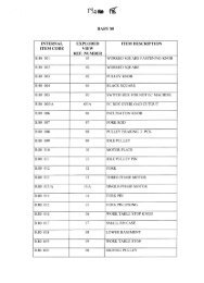
EQUIPAGGIAMENTI POSSIBILI<br />
AVAILABLE EQUIPMENT<br />
T <strong>521</strong> <strong>SNC</strong><br />
T <strong>521</strong> <strong>OPT</strong><br />
D<br />
E<br />
D<br />
E<br />
La macchina T <strong>521</strong> può essere venduta nelle configurazioni<br />
<strong>SNC</strong>, <strong>OPT</strong> e ST (per la versione ST esiste un Manuale di<br />
Uso e Manutenzione diverso da questo).<br />
T <strong>521</strong> <strong>SNC</strong> include l’apparato FP The Fine Positioner* (da<br />
4000 o 6000 mm di lavoro utile) attrezzato con carrello a<br />
NC, spintore con pinza e software.<br />
T <strong>521</strong> <strong>OPT</strong> include l’apparato FP The Fine Positioner* (da<br />
4000 o 6000 mm di lavoro utile) attrezzato con carrello a<br />
NC, spintore con pinza, marcatore laser per la rilevazione dei<br />
difetti della barra da tagliare, hardware e software dedicati.<br />
In tutti e due i casi, in posizione di scarico (D) possono essere<br />
collegati alla macchina scelta dispositivi quali:<br />
• Nulla (equipaggiamento a carico e responsabilità<br />
del’Utilizzatore)<br />
• Rulliera folle<br />
• Piano di scorrimento<br />
• Tappeto motorizzato**<br />
* L’apparato “FP The Fine Positioner” è fornito con:<br />
• Manuale di Uso & Manutenzione<br />
• Manuale del Software:<br />
SPINTORE per la versione T <strong>521</strong> <strong>SNC</strong><br />
<strong>OPT</strong> per la versione T <strong>521</strong> <strong>OPT</strong><br />
** Nel caso di equipaggiamento motorizzato in posizione<br />
di scarico (D) è disponibile il selezionatore meccanico (1).<br />
The T <strong>521</strong> machine is offered in the following versions: <strong>SNC</strong>,<br />
<strong>OPT</strong> and ST (for the ST version there is a Use and<br />
Maintenance Manual different to this one).<br />
T <strong>521</strong> <strong>SNC</strong> includes the FP Fine Positioner* (with an actual<br />
working area of 4000 or 6000 mm), equipped with the NC<br />
carriage, pusher with gripper and software.<br />
T <strong>521</strong> <strong>OPT</strong> includes the FP Fine Positioner* (with an actual<br />
working area of 4000 or 6000 mm), equipped with NC<br />
carriage, pusher with gripper, laser marker for detecting defects<br />
in the bar to cut, dedicated hardware and software.<br />
In all two cases, the unloading station (D) can be fitted with<br />
devices such as:<br />
• None (equipment at the charge and care of the User)<br />
• Idle roller way<br />
• Transport table<br />
• Motorised conveyor**<br />
* The “FP Fine Positioner” is supplied with:<br />
• User Manual<br />
• Software Handbook:<br />
PUSHER for the T <strong>521</strong> <strong>SNC</strong><br />
<strong>OPT</strong> for the T <strong>521</strong> <strong>OPT</strong><br />
** If the unloading station (D) features motorised equipment,<br />
is available the Mechanical Workpiece Sorter (1).<br />
12 T <strong>521</strong> <strong>SNC</strong> / <strong>OPT</strong>
EQUIPAGGIAMENTI POSSIBILI<br />
AVAILABLE EQUIPMENT<br />
1<br />
MODAL<strong>ITA</strong>’ DI MOVIMENTAZIONE<br />
E DI SOLLEVAMENTO<br />
HANDLING AND LIFTING<br />
PRO<strong>CE</strong>DURE<br />
Indipendentemente dall’equipaggiamento e dalla tipologia di<br />
macchina (<strong>SNC</strong> / <strong>OPT</strong>), l’Utilizzatore che si appresti a<br />
collocarla nella postazione di lavoro o che debba spostarla<br />
deve innanzitutto separare le parti che la compongono<br />
(dispositivi in carico, dispositivi in scarico, eventuali<br />
periferiche).<br />
Dispositivi in carico (E) - Dispositivi in scarico (D)<br />
Ognuna delle parti descritte nel capitolo precedente è dotata<br />
di piedi atti a sostenerla in modo stabile e sicuro anche se<br />
separata dalla macchina.<br />
Dovendo sollevare queste parti è indispensabile l’utilizzo di<br />
un carrello elevatore (A) le cui forche dovranno essere<br />
posizionate in prossimità del loro baricentro.<br />
Irrespective of the equipment and type of machine (<strong>SNC</strong> /<br />
<strong>OPT</strong>), before actually moving the machine or putting it in its<br />
intended working position, the user must first of all separate<br />
the parts composing it (loading and unloading devices, any<br />
peripheral units).<br />
Loading devices (E) - Unloading devices (D)<br />
All the equipment described in the previous chapter is<br />
equipped with feet that offer safe and stable support of each<br />
component, even if this is not connected to the machine.<br />
All parts must be lifted with a forklift truck (A) that must be<br />
placed in correspondence with their centre of gravity.<br />
T <strong>521</strong> <strong>SNC</strong><br />
T <strong>521</strong> <strong>OPT</strong><br />
D<br />
E<br />
D<br />
E<br />
F<br />
A<br />
B<br />
C<br />
T <strong>521</strong> <strong>SNC</strong> / <strong>OPT</strong><br />
13
MODAL<strong>ITA</strong>’ DI MOVIMENTAZIONE<br />
E DI SOLLEVAMENTO<br />
Il corpo macchina T <strong>521</strong> può essere sollevato utilizzando un<br />
carrello elevatore (A) posizionando le forche nei piedi (F).<br />
In mancanza di carrello elevatore, l’Operatore, con l’aiuto di<br />
una seconda persona, dovrà sollevare la macchina,<br />
inclinandola verso sinistra o destra, quel tanto che basti<br />
per far passare le forche di un transpallet (B) o per posizionare<br />
un pallet (C), in questo caso la macchina dovrà essere fatta<br />
scivolare nel centro del pallet per ottenerne la massima<br />
stabilità.<br />
Lo spostamento della macchina, adagiata sul pallet (C), deve<br />
essere effettuato utilizzando il transpallet (B) o il carrello<br />
elevatore (A).<br />
La composizione della configurazione scelta, prevede<br />
ovviamente l’accostamento delle altre parti e i successivi:<br />
• collegamenti meccanici<br />
• collegamenti elettrici e pneumatici, ove previsto<br />
• livellamento (capitolo successivo)<br />
• fissaggio al suolo (capitolo successivo)<br />
COME SOLLEVARE IL PIANO DI LAVORO<br />
(FP The Fine Positioner)<br />
Dopo aver separato il piano di lavoro dal corpo macchina, è<br />
indispensabile posizionare le staffe in dotazione (1 e 2) così<br />
come indicato nelle figure di questa pagina; si raccomanda<br />
in ogni caso di individuare l’esatto baricentro prima di cominciare<br />
il sollevamento, tanto nella modalità 1 quanto nella<br />
modalità 2 (indicate nella pagina di fronte).<br />
Le staffe, fornite in dotazione, sono individuabili con il codice<br />
38123.<br />
HANDLING AND LIFTING<br />
PRO<strong>CE</strong>DURE<br />
The machine body of the T <strong>521</strong> can be lifted with a forklift<br />
truck (A). Forks should be placed in the feet (F).<br />
If forklift trucks are not available, the operator can lift the<br />
machine, with the aid of another person, by tilting it leftwards<br />
or rightwards enough to enable the insertion of the forks of<br />
a pallet transfer car (B) or of a pallet (C). In the latter case,<br />
the machine must be pushed to the centre of the pallet to obtain<br />
the maximum stability.<br />
Transport of the machine on a pallet (C) must be effected by<br />
a pallet transfer car (B) or a forklift truck (A).<br />
Depending on the configuration of your machine, the other<br />
components will thus be put in place and the following<br />
provided:<br />
• mechanical connections<br />
• electrical connections and, if necessary, connection to the<br />
compressed air supply<br />
• levelling (next chapter)<br />
• securing to the floor (next chapter)<br />
LIFTING THE WORKTABLE<br />
(FP The Fine Positioner)<br />
After separating the worktable from the machine body, you<br />
must position the brackets supplied (1 and 2) as indicated in<br />
the diagrams on this page.<br />
Always find the exact centre of gravity before you start lifting,<br />
either with method 1 or with method 2 (see opposite<br />
page).<br />
The brackets supplied are marked with code 38123.<br />
14 T <strong>521</strong> <strong>SNC</strong> / <strong>OPT</strong>
MODAL<strong>ITA</strong>’ DI MOVIMENTAZIONE<br />
E DI SOLLEVAMENTO<br />
HANDLING AND LIFTING<br />
PRO<strong>CE</strong>DURE<br />
T <strong>521</strong> <strong>SNC</strong> / <strong>OPT</strong><br />
15
MODAL<strong>ITA</strong>’ DI MOVIMENTAZIONE<br />
E DI SOLLEVAMENTO<br />
HANDLING AND LIFTING<br />
PRO<strong>CE</strong>DURE<br />
PUNTI DI APPOGGIO<br />
LIVELLAMENTO E FISSAGGIO<br />
SUPPORT POINTS, LEVELLING AND<br />
FIXING<br />
F<br />
4<br />
3<br />
1<br />
2<br />
16 T <strong>521</strong> <strong>SNC</strong> / <strong>OPT</strong>
PUNTI DI APPOGGIO<br />
LIVELLAMENTO E FISSAGGIO<br />
CORPO MACCHINA<br />
Dopo avere collocato la macchina nel posto di lavoro, è<br />
necessario fissarla al suolo per assicurarle la massima<br />
stabilità e sicurezza operativa.<br />
Procedere come segue:<br />
• accertare che la macchina sia appoggiata su una superficie<br />
piana e possibilmente uniforme e che il locale sia<br />
sufficientemente illuminato;<br />
• effettuare i controlli di planarità e di livellamento mediante<br />
una livella a bolla di controllo*; per eventuali regolazioni,<br />
allentare i controdadi di bloccaggio (1) ed avvitare o svitare<br />
le quattro viti (2) sui piedi (F);<br />
• raggiunto il corretto livellamento della macchina, serrare i<br />
controdadi di bloccaggio (1);<br />
• fissare la macchina al suolo praticando fori sul pavimento in<br />
corrispondenza delle sedi (3) predisposte sui piedi di appoggio<br />
ed infilandovi viti ad espansione (4), non in dotazione.<br />
* Rammentare che il piano di lavoro della macchina è inclinato<br />
di 10°.<br />
DISPOSITIVI IN CARICO (E)<br />
DISPOSITIVI IN SCARICO (D)<br />
Dopo aver avvicinato al corpo macchina i dispositivi E e D, è<br />
necessario livellarli e fissarli meccanicamente ad essa con le<br />
staffe e le viti fornite in dotazione.<br />
Per il collegamento meccanico dell’unità FP alla troncatrice<br />
vedere capitolo “Come collegare FP...” a pag. 17.<br />
IMPORTANTE<br />
Il livellamento di questi dispositivi deve essere fatto tenendo<br />
come riferimento l’altezza da terra del piano di taglio della<br />
macchina T <strong>521</strong>; per fare questa operazione l’Operatore dovrà<br />
servirsi di un metro e di una livella a bolla di controllo<br />
sufficientemente lunga.<br />
Fatto il livellamento è indispensabile procedere al fissaggio<br />
al suolo dei vari dispositivi E e D.<br />
Livellamento e fissaggio si effettuano facilmente e<br />
rapidamente; basterà che l’Operatore segua le istruzioni già<br />
evidenziate alla pagina precedente e attinenti al “corpo<br />
macchina”.<br />
ATTENZIONE:<br />
Terminate queste operazioni, un operaio specializzato potrà<br />
effettuare i collegamenti elettrici e pneumatici, se previsti.<br />
Questo intervento deve essere effettuato PRIMA di collegare<br />
la macchina e gli eventuali dispositivi E e D a qualsiasi fonte<br />
di energia esterna.<br />
SUPPORT POINTS, LEVELLING AND<br />
FIXING<br />
MACHINE BODY<br />
After placing the machine in the work position, it must be<br />
fixed to the ground to ensure maximum stability and<br />
operating security.<br />
Follow this procedure:<br />
• make sure the machine is resting on a flat and possibly<br />
smooth surface and that the work environment is<br />
sufficiently lit;<br />
• use a spirit level to check that the machine is flat and<br />
levelled*. To adjust, loosen the fixing nuts (1) and tighten or<br />
loosen the four screws (2) on the feet (F);<br />
• When the correct level has been reached, tighten the fixing<br />
nuts (1).<br />
• Fix the machine to the ground by making holes in the floor<br />
at the seats (3) arranged on the support feet and inserting the<br />
expansion plugs (4) that are not supplied.<br />
* Remember that the machine’s transport table is tilted by<br />
10°.<br />
LOADING DEVI<strong>CE</strong>S (E)<br />
UNLOADING DEVI<strong>CE</strong>S (D)<br />
After moving devices E and D near to the machine, level them<br />
and secure them to the machine using the brackets and screws<br />
provided.<br />
For the mechanical connection of the FP unit to the up-stroking<br />
saw see chapter “How to connect the FP…” at page 17.<br />
IMPORTANT<br />
These devices must be levelled using the height of the cutting<br />
table of the T <strong>521</strong> machine as reference; to do so, the operator<br />
must be using a tape measure and a sufficiently long spirit<br />
level.<br />
Once they have been levelled, fasten devices E and D to the<br />
floor.<br />
Levelling and fixing are both easy and quick; the operator<br />
should simply follow the instructions given on the previous<br />
page that concern the “machine body”.<br />
WARNING:<br />
Once these operations have been completed, a qualified<br />
worker must provide the electrical and, if necessary, the<br />
compressed air supply connections. These operations must<br />
be effected BEFORE connecting the machines and devices<br />
E and D to any source of energy.<br />
T <strong>521</strong> <strong>SNC</strong> / <strong>OPT</strong><br />
17
INGOMBRI E PESO<br />
DIMENSIONS AND WEIGHT<br />
T <strong>521</strong> <strong>OPT</strong><br />
B<br />
A<br />
C<br />
A = 1400 mm<br />
B = 680 mm<br />
C = 925 mm<br />
Kg<br />
370<br />
DISPOSITIVI IN CARICO (E)<br />
DISPOSITIVI IN SCARICO (D)<br />
Dimensioni e pesi dei dispositivi E e D sono specificati a<br />
parte nei relativi manuali.<br />
LOADING DEVI<strong>CE</strong>S (E)<br />
UNLOADING DEVI<strong>CE</strong>S (D)<br />
Dimensions and weight of devices E and D are described in<br />
the relevant handbooks.<br />
T <strong>521</strong> <strong>SNC</strong><br />
FP 4000 = Kg 137<br />
FP 6000 = Kg 206<br />
T <strong>521</strong> <strong>OPT</strong><br />
FP 4000 = Kg 186<br />
FP 6000 = Kg 283<br />
18 T <strong>521</strong> <strong>SNC</strong> / <strong>OPT</strong>
COME COLLEGARE FP ALLA<br />
TRONCATRI<strong>CE</strong> T <strong>521</strong><br />
HOW TO CONNECT THE FP TO<br />
THE T <strong>521</strong> SAW<br />
T <strong>521</strong> <strong>SNC</strong> - T <strong>521</strong> <strong>OPT</strong> 4000 mm<br />
Y<br />
T<br />
P<br />
F<br />
P<br />
F<br />
S<br />
T<br />
T <strong>521</strong> <strong>SNC</strong> - T <strong>521</strong> <strong>OPT</strong> 6000 mm<br />
P<br />
N<br />
Y<br />
H<br />
M<br />
P<br />
F<br />
S<br />
T<br />
S<br />
Q<br />
Q<br />
T - Piano di lavoro T <strong>521</strong> <strong>SNC</strong><br />
S - Piano di lavoro T <strong>521</strong> <strong>OPT</strong><br />
Y - Trave di FP The Fine Positioner<br />
P - Piastrino bloccaggio 60 x 20 x 6 Code 35685<br />
H - Rondella comune tranciata 8 x 24 x 2 Code 1000202300<br />
M - Vite T.P.S.E.I. 8 x 20 Code 1100702000<br />
F - Fori su T ed S<br />
N - Sponda prolunga trave <strong>OPT</strong> Code 38003<br />
Q - Sezione di Y (trave di FP)<br />
T - Working table T <strong>521</strong> <strong>SNC</strong><br />
S - Working table T <strong>521</strong> <strong>OPT</strong><br />
Y - Beam of the FP The Fine Positioner<br />
P - Locking plate 60 x 20 x 6 Code 35685<br />
H - Kasher 8 x 24 x 2 Code 1000202300<br />
M - Screw T.P.S.E.I. 8 x 20 Code 1100702000<br />
F - Drills on T and S<br />
N - <strong>OPT</strong> bar extension fence Code 38003<br />
Q - Section of Y (FP bar)<br />
T <strong>521</strong> <strong>SNC</strong> / <strong>OPT</strong><br />
19
MARCATURA DI SICUREZZA<br />
SAFETY MARKING<br />
CODE: 24873<br />
CODE: _____<br />
CODE: 24873<br />
CODE: 31996<br />
CODE: 24875<br />
CODE: 24874<br />
CODE: 38410<br />
20 T <strong>521</strong> <strong>SNC</strong> / <strong>OPT</strong>
MARCATURA DI SICUREZZA<br />
SAFETY MARKING<br />
LEGENDA:<br />
KEY:<br />
Codice 24873:<br />
targa vietato introdurre le mani<br />
Code 24873:<br />
do not insert hands sticker<br />
Codice 24874:<br />
targa sezionamento energia elettrica<br />
Code 24874:<br />
electrical power isolation sticker<br />
Codice 24875:<br />
targa punto allacciamento elettrico<br />
Code 24875:<br />
electrical connection sticker<br />
Codice 31996:<br />
targa pittogrammi<br />
Code 31996:<br />
pictogram sticker<br />
Codice 38410:<br />
targa z-laser<br />
Code 38410:<br />
z-laser sticker<br />
Attenzione:<br />
nel caso in cui le targhe siano illeggibili o siano state rimosse,<br />
sostituirle immediatamente.<br />
Non utilizzare la macchina se priva di una o più targhe.<br />
Warning:<br />
if the plates are illegible or have been removed, replace them<br />
immediately.<br />
Never use the machine if any of the plates is missing.<br />
DISPOSITIVI DI SICUREZZA<br />
SAFETY DEVI<strong>CE</strong>S<br />
È compito dell’acquirente istruire il proprio personale<br />
circa l’utilizzo delle protezioni e dei dispositivi di sicurezza<br />
menzionati in questa sezione del manuale d’uso &<br />
manutenzione.<br />
L’utilizzo improprio, la manomissione o la rimozione dei<br />
dispositivi di sicurezza, comporta il decadimento<br />
immediato della garanzia e, nel caso di eventuali infortuni<br />
a persone, OMGA S.p.A. non può esserne ritenuta<br />
responsabile.<br />
The purchaser must instruct his staff in the use of the<br />
guards and safety devices mentioned in this part of the<br />
user manual.<br />
Incorrect use, tampering with or removal of the safety<br />
devices immediately voids the warranty and exempts<br />
OMGA S.p.A. from any liability for death, injury or<br />
damage.<br />
1<br />
2<br />
K<br />
3<br />
4<br />
T <strong>521</strong> <strong>SNC</strong> / <strong>OPT</strong><br />
21
DISPOSITIVI DI SICUREZZA<br />
SAFETY DEVI<strong>CE</strong>S<br />
10<br />
6<br />
5<br />
9<br />
7<br />
6<br />
11 11<br />
01 Rete anti-intrusione (area di taglio)<br />
Per la T <strong>521</strong> questa protezione ha dimensioni in lunghezza<br />
pari a quanto previsto dalle norme vigenti.<br />
Per le versioni T <strong>521</strong> <strong>SNC</strong> e <strong>OPT</strong>, pur essendo presente questa<br />
protezione, i comandi di avvio ciclo sono lontani dall’area di<br />
taglio e quindi fuori da qualsiasi situazione di rischio.<br />
02 Pulsante a fungo di EMERGENZA<br />
Per le versioni <strong>SNC</strong> e <strong>OPT</strong> il comando è collocato sulla<br />
console del controllo numerico (posizione K).<br />
Questo comando deve essere premuto:<br />
a) per arrestare il motore al termine del ciclo di lavoro*<br />
b) nel caso insorga una situazione di emergenza*<br />
* In entrambi i casi il motore si arresta e la rotazione della<br />
lama cessa entro i 10 secondi previsti dalla normatica prEN-<br />
1870-16 attualmente in vigore.<br />
Per il ripristino delle normali condizioni di utilizzo della<br />
macchina è sufficiente riarmare il pulsante a fungo di<br />
EMERGENZA (dopo aver eliminato l’eventuale causa che<br />
nè ha determinato l’azionamento).<br />
03 Interruttore sezionatore energia elettrica<br />
Ruotato in posizione (I) alimenta il quadro elettrico della<br />
macchina.<br />
Ruotato in posizione (0)** taglia l’energia elettrica, per cui<br />
sarà possibile all’Operatore intervenire in sicurezza per<br />
eventuali necessità di controlli o manutenzioni.<br />
01 Net preventing access (cutting area)<br />
As far as the T <strong>521</strong> is concerned, this guard have the length<br />
established by the standards in force.<br />
As far as versions T <strong>521</strong> <strong>SNC</strong> and <strong>OPT</strong> are concerned, this<br />
guard are provided. However, the cycle start controls are far<br />
from the cutting area and therefore outside the danger zone.<br />
02 Mushroom-head EMERGENCY STOP push-button<br />
For <strong>SNC</strong> and <strong>OPT</strong> versions the control is located on the numeric<br />
control console (position K).<br />
This control must be pressed:<br />
a) to stop the motor at the end of the work cycle*<br />
b) in the event of an emergency*<br />
* In both cases, the motor stops and the blade stops spinning<br />
within 10 seconds, as established by the prEN-1870-16<br />
standard currently in force.<br />
To resume normal operating conditions, reset the<br />
EMERGENCY switch (after eliminating the cause of its<br />
activation).<br />
03 Switch/Circuit breaker<br />
Turning this to (I) powers the machine’s electrical cabinet.<br />
Turning it to (0)** cuts off the electricity supply in order to<br />
enable the operator to carry out any checks or maintenance in<br />
safe working conditions.<br />
22 T <strong>521</strong> <strong>SNC</strong> / <strong>OPT</strong>
DISPOSITIVI DI SICUREZZA<br />
SAFETY DEVI<strong>CE</strong>S<br />
** L’Interruttore è lucchettabile: si raccomanda<br />
all’Operatore che lasci incustodita la macchina per qualche<br />
tempo o che debba effettuare manutenzione di ruotarlo in<br />
posizione (0) e di inserire il lucchetto (non fornito) per evitare<br />
che a sua insaputa chiunque possa rialimentare la macchina.<br />
<strong>04</strong> Pressostato di sicurezza<br />
E’ collocato all’interno del quadro elettrico.<br />
Ha la funzione di sorvegliare i cali di pressione. Sotto i 3 bar<br />
si ha il suo intervento con conseguente blocco della macchina.<br />
In questo caso si consiglia di verificare le cause che hanno<br />
determinato il calo di pressione.<br />
05 Sezionatore aria pneumatica<br />
Dispositivo lucchettabile. Permette all’Operatore che debba<br />
attuare manutenzione o che debba lasciare ferma la nacchina<br />
in sua assenza, di scollegarla dall’alimentazione generale e di<br />
scaricare l’aria residua dal circuito pneumatico interno.<br />
Si ha l’obbligo di inserire un lucchetto (non fornito) nel<br />
caso in cui la macchina risulti ferma per manutenzione o guasti.<br />
06 Micro-interruttore di sicurezza<br />
Montato sul lato posteriore del carter copri-lama (11) ha la<br />
funzione di arrestare istantaneamente la macchina in caso di<br />
apertura del carter stesso.<br />
07 Pomello di bloccaggio del carter copri-lama<br />
Questo pomello serve, svitandolo, a liberare il carter coprilama<br />
(11) per avere accesso all’untensile. Il carter rimane<br />
vincolato alla macchina ed è anche dotato del microinterruttore<br />
di sicurezza (06).<br />
Lo stelo della vite di questo pomello è lungo quanto basta per<br />
far sì che il suo allentamento richieda molto più tempo di<br />
quanto ne occorra alla lama per arrestarsi.<br />
L’arresto lama è tutelato comunque dal freno-motore.<br />
09 Pressore di sicurezza<br />
Alloggiato all’interno del carter superiore (10) è pilotato da<br />
un cilindro pneumatico in ciclo col comando di START.<br />
L’azionamento del comando START provoca la discesa di<br />
questo pressore che va a bloccare sul piano di lavoro il pezzo<br />
da tagliare. La conformazione del pressore è tale da fungere<br />
anche da protezione in quanto l’utensile, durante la sua salita<br />
per il taglio, è totalmente coperto nella parte superiore, oltre<br />
a ciò il pressore impedisce proiezioni di schegge indesiderate<br />
generate dalla fase di taglio (intestatura eccessivamente corta,<br />
nodi, ecc.).<br />
In caso di malfunzionamento o di guasti, leggere al prossimo<br />
paragrafo (10) e poi seguire in pagina successiva.<br />
10 Carter superiore<br />
Vedi anche a pag. 22.<br />
Protetto a destra e a sinistra dalle reti antiintrusione (1) copre<br />
per intero l’area di taglio e il campo d’azione della lama. E’<br />
inamovibile e inaccessibile al suo interno se non per manutenzioni<br />
straordinarie***.<br />
** The switch can be padlocked: in the event that the machine<br />
has to be left unattended or that the operator has to perform<br />
maintenance operations, it is recommended to turn the switch<br />
off (0) and padlock it in this position (the padlock is not<br />
supplied) to prevent the machine from being accidentally<br />
powered.<br />
<strong>04</strong> Safety pressure switch<br />
This is located in the electrical cabinet.<br />
It supervises drops in pressure. It intervenes below 4 bar to<br />
stop the machine.<br />
In this case check the causes of the drop in pressure.<br />
05 Compressed air cutoff valve<br />
Device that can be padlocked. This device enables operators<br />
who have to perform maintenance, or have to leave the<br />
machine stationary whilst it is unattended, to disconnect it<br />
from the main supply and to discharge residual air from the<br />
internal compressed air circuit.<br />
The machine must be padlocked (padlock is not supplied) if<br />
the machine is stationary because of maintenance or faults.<br />
06 Micro safety switch<br />
This is placed on the blade guard (11). It brings the machine<br />
to an immediate stop if the guard is opened.<br />
07 Knob to lock the blade guard<br />
This knob locks and releases the blade guard (11) to give<br />
access to the tool. The guard remains fastened to the machine<br />
and is fitted with a safety micro switch (06).<br />
Owing to the length of the shank of the knob’s screw, loosening<br />
the knob takes a longer time than that taken by the blade to<br />
stop.<br />
Blade stopping is in any case controlled by the motor brake.<br />
09 Safety presser<br />
Located behind the top guard (10) and controlled by a<br />
pneumatic cylinder operating combined with the START key.<br />
Activating the START key lowers this presser that blocks the<br />
workpiece on the workbench. The shape of the clamp also<br />
offers a safety function. It in fact covers the top section of the<br />
cutting tool during its upstroke for cutting and prevents the<br />
projection of splinters that may result from the cutting<br />
operations (excessively short butting cuts, knots, etc.).<br />
If the machine is not working properly or is faulty, read the<br />
next paragraph (10) and follow the instructions given on the<br />
next page.<br />
10 Top guard<br />
See also page 22.<br />
Protected on the left and right by the nets preventing access<br />
(1), it covers the entire cutting area and operating range of the<br />
blade. It cannot be moved and the parts behind cannot be<br />
accessed, unless for extra-duty maintenance***.<br />
T <strong>521</strong> <strong>SNC</strong> / <strong>OPT</strong><br />
23
DISPOSITIVI DI SICUREZZA<br />
SAFETY DEVI<strong>CE</strong>S<br />
*** Se l’azionamento del pressore interno (9) dovesse richiedere<br />
interventi (sostituzione del cilindro), innanzitutto si dovrà<br />
disconnettere la macchina da qualsiasi fonte di energia<br />
esterna e si dovrà scaricare l’aria residua mediante il sezionatore<br />
(5) posto sul gruppo filtro.<br />
• Rimuovere la rete antiintrusione (1),<br />
• Dal carter (10) svitare e togliere le viti (14), rimuovere la<br />
copertura sinistra (M),<br />
***If the activation of the internal presser (9) calls for<br />
maintenance operations (for instance the replacement of the<br />
cylinder), first of all disconnect the machine from energy<br />
sources and discharge residual air with the cutoff valve (5)<br />
on the filter unit.<br />
• Remove the net preventing access (1),<br />
• Loosen and remove the screws (14) from the guard (10) and<br />
remove the left hand cover (M).<br />
14<br />
M<br />
10<br />
15<br />
9<br />
13<br />
12<br />
16 17<br />
7<br />
11<br />
11<br />
P<br />
18<br />
21<br />
24 T <strong>521</strong> <strong>SNC</strong> / <strong>OPT</strong>
DISPOSITIVI DI SICUREZZA<br />
SAFETY DEVI<strong>CE</strong>S<br />
22<br />
1<br />
N1<br />
19<br />
N1<br />
N<br />
20<br />
Per proseguire sarà necessario smontare la lama (12). Questa<br />
procedura è descritta nel capitolo “Sostituzione della lama”.<br />
Per accedere alla posizione (13) dove è collocato il cilindro<br />
che controlla l’azionamento del pressore (9) svitare il pomello<br />
(7) e abbassare il carter copri-lama (11) che rimane comunque<br />
vincolato alla macchina. Rimossa la copertura (M)<br />
si potranno svitare e togliere le quattro viti a brugola (in posizione<br />
17) che trattengono al piano di lavoro (16) il cilindro<br />
collocato in posizione (13). Smontare il cilindro, rimontare il<br />
nuovo e seguire in modo inverso la procedura per rimettere<br />
come in origine tutte le parti precedentemente smontate. In<br />
posizione (15) e solo a titolo informativo, è montata internamente<br />
al carter (10) la guida di scorrimento del pressore interno<br />
(9).<br />
18 Valvola snodata<br />
Questa valvola, quando sollecitata, provoca la discesa del<br />
pressore (9) prima che la lama sia salita per l’esecuzione del<br />
taglio. Una volta alla settimana o più frequentemente, in base<br />
alla durata e intensità dei periodi di lavoro, si raccomanda<br />
di pulire il vano motore (P) in cui essa è alloggiata e di<br />
soffiare aria con una condotta pneumatica per liberarla<br />
da eventuali incrostazioni (segatura+umidità) che potrebbero<br />
impedirne il corretto funzionamento.<br />
L’accesso al vano motore (P) è possibile aprendo il carter<br />
destro (N) che è incernierato al telaio della macchina con due<br />
cerniere (19); svitare il pomello (20) e ruotare in fuori il carter<br />
per accedere all’interno.<br />
21 Micro-interruttore di sicurezza<br />
Montato sul carter destro (N) ha la funzione di arrestare istantaneamente<br />
la macchina in caso di apertura del carter stesso.<br />
22 Microinterruttore di sicurezza<br />
Montato sul carter destro superiore (N1) ha la funzione di<br />
arrestare istantaneamente la macchina in caso di apertura del<br />
carter stesso.<br />
To continue, you will now have to remove the blade (12).<br />
This procedure is described in the “Replacing the blade”<br />
chapter.<br />
To gain access to the position (13) in which the cylinder driving<br />
the clamp (9) is activated, loosen the knob (7) and lower the<br />
blade guard (11), which will in any case remain attached to<br />
the machine. Once the cover (M) has been removed, you can<br />
loosen and remove the four Allen screws (in position 17) that<br />
hold the cylinder in position (13) in place on the table (16).<br />
Remove the cylinder, replace it and reassemble all parts<br />
removed by following the above instructions in reverse order.<br />
The sliding guide of the internal presser (9) is fitted behind<br />
the casing (10), in positions (15) and (9).<br />
18 Articulated valve<br />
When activated, this valve lowers the presser (9) before the<br />
blade rises to perform a cut. Once a week, or more frequently,<br />
depending on the duration and intensity of the work cycles, it<br />
is highly recommended to clean the motor compartment<br />
(P) in which it is installed and to blow the pneumatic duct<br />
with air to remove any dirt (sawdust+damp) that would<br />
prevent correct operation.<br />
To access the motor compartment (P) open the right-hand<br />
guard (N) which is hinged to the machine frame by two hinges<br />
(19). Unscrew the knob (20) and turn the guard outwards<br />
for access to the compartment.<br />
21 Safety microswitch<br />
Fitted on the right-hand guard panel (N), this microswitch<br />
instantaneously stops the machine in the event that the guard<br />
panel is opened.<br />
22 Safety microswitch<br />
Fitted on the upper right-hand guard panel (N1), this<br />
microswitch instantaneously stops the machine in the event<br />
that the guard panel is opened.<br />
T <strong>521</strong> <strong>SNC</strong> / <strong>OPT</strong><br />
25
DISPOSITIVI DI SICUREZZA<br />
SAFETY DEVI<strong>CE</strong>S<br />
ATTENZIONE: anche in questo caso, prima di iniziare interventi<br />
di ispezione e/o manutenzione è obbligatorio disconnettere<br />
dalla macchina qualsiasi fonte di energia esterna.<br />
Richiudere il carter (N) subito dopo aver effettuato l’ispezione<br />
o la manutenzione descritta in questo paragrafo.<br />
AVVERTENZA<br />
I dispositivi di sicurezza montati sui dispositivi in carico (E<br />
pag. 11) e scarico (D pag. 11) sono descritti sul relativo manuale<br />
fornito a corredo.<br />
WARNING: also in this case, disconnect the machine from<br />
any energy source, before carrying out any inspection and/<br />
or maintenance.<br />
Close the guard (N) again immediately after your inspection<br />
or maintenance described in this section.<br />
WARNING<br />
The safety devices fitted to the loading (E, page 11) and<br />
unloading devices (D, page 11) are described in the relevant<br />
handbooks provided.<br />
COLLEGAMENTO ELETTRICO<br />
WIRING<br />
Q<br />
3<br />
R<br />
S<br />
2<br />
L1<br />
L2<br />
20<br />
L3<br />
ATTENZIONE:<br />
Il quadro elettrico si trova sul fianco destro della macchina<br />
nel vano ed è protetto dal coperchio (Q) che è dotato di serratura<br />
a chiave (l’Operatore non dovrà lasciare la chiave inserita,<br />
soprattutto quando la macchina sarà incustodita).<br />
Sarà cura di uno specialista collegare sull’interruttore interno<br />
(20) un cavo a tre fili + massa (L1-L2-L3 + terra) idoneo<br />
per sezione e portata.<br />
WARNING:<br />
The electrical panel is on the right-hand side of the machine<br />
inside the compartment and is protected by the cover (Q)<br />
which has a key lock (never leave the key in the lock, especially<br />
when the machine is unattended).<br />
A qualified electrician must connect a cable with three<br />
wires+earth (L1-L2-L3 + earth), with a suitable size and<br />
capacity to the internal switch (20).<br />
26 T <strong>521</strong> <strong>SNC</strong> / <strong>OPT</strong>
COLLEGAMENTO ELETTRICO<br />
WIRING<br />
Sarà cura di uno specialista montare sui capi (L1-L2-L3) e<br />
sul cavo di terra (giallo-verde) una spina idonea per portata<br />
per la connessione alla fonte di energia elettrica esterna.<br />
Versioni <strong>SNC</strong> e <strong>OPT</strong><br />
Gli eventuali dispositivi in carico (E pag. 11) e scarico (D<br />
pag. 11), ove sia previsto, sono provvisti del manuale d’uso<br />
in cui sono contenute le istruzioni per il corretto collegamento<br />
elettrico.<br />
RACCOMANDAZIONE<br />
In caso di necessità di effettuare qualsiasi tipo di manutenzione,<br />
è necessario premere prima il pulsante di EMERGEN-<br />
ZA (2 pag. 24) e poi sezionare l’energia elettrica ruotando in<br />
posizione orizzontale (0) l’interruttore/sezionatore (3 pag. 24).<br />
Una volta effettuati i collegamenti, si raccomanda di verificare<br />
il corretto senso di rotazione della lama.<br />
PROVA DI AC<strong>CE</strong>NSIONE DEL MOTORE<br />
Ruotando in posizione verticale (I) l’interruttore/sezionatore<br />
(3 pag. 24) si fornisce energia elettrica alla macchina e la spia<br />
bianca (R) si illumina.<br />
Azionando il pulsante/spia verde (S) si accende la spia verde<br />
e il motore della lama si mette in moto.<br />
Per arrestare il motore lama è indispensabile premere il pulsante<br />
di EMERGENZA (2 pag. 24); si raccomanda di non<br />
provocare l’arresto del motore agendo sull’interruttore/<br />
sezionatore (3 pag. 24).<br />
The electrician must also fit a plug with a suitable capacity<br />
to the leads (L1 - L2 - L3) and to the earthing wire (yellowgreen)<br />
for connection to the external energy source.<br />
Versions <strong>SNC</strong> and <strong>OPT</strong><br />
The loading devices (E page 11) and unloading devices (D<br />
page 11), when envisaged, are provided with user manuals<br />
giving all the instructions for correct wiring.<br />
RECOMMENDATION<br />
Before carrying out any type of maintenance, first press<br />
the EMERGENCY switch (2, page 24) and then isolate the<br />
mains by turning the circuit breaker (3, page 24) to its<br />
horizontal position (0).<br />
After wiring, make sure that the blade spins in the right<br />
direction.<br />
MOTOR TEST RUN<br />
Turn the circuit breaker (3, page 24) to its vertical position<br />
(I) to power the machine. The white Power indicator light<br />
(R) will come on.<br />
Press the button with green light (S): the green light should<br />
come on and the blade motor should start running.<br />
To stop the blade motor, you must press the EMERGENCY<br />
switch (2, page 24); do not stop the motor with the switch/<br />
circuit breaker (3, page 24).<br />
COLLEGAMENTO PNEUMATICO<br />
PNEUMATIC CONNECTIONS<br />
ATTENZIONE:<br />
Questo intervento deve essere eseguito da personale<br />
qualificato.<br />
La macchina è dotata di un punto di allacciamento pneumatico<br />
attrezzato con gruppo filtro riduttore lubrificatore e con<br />
dispositivo di scarico rapido della condensa.<br />
ATTENZIONE: Verificare che all’interno del serbatoio (1)<br />
sia sempre presente olio per almeno i due terzi della sua<br />
capacità. Effettuare il collegamento all’impianto di<br />
alimentazione pneumatica utilizzando una idonea condotta<br />
in gomma e fissandola con fascetta metallica all’innesto (10).<br />
Verificare che la pressione di alimentazione, segnalata dal<br />
manometro (2) del gruppo filtro corrisponda a 6÷7 bar.<br />
WARNING:<br />
This task must be performed by qualified personnel .<br />
The machine has a fitted compressed-air point with a<br />
lubricator reduction gear filter unit and with a device that<br />
rapidly discharges condensate.<br />
WARNING: Make sure the tank (1) is at least two thirds<br />
full.<br />
Use a suitable rubber pipe to connect the compressed-air<br />
supply and fix it with a metal clip to the fitting (10).<br />
Ensure that operating pressure, shown on gauge (2) of the<br />
filter unit, is 6 or 7 bar.<br />
T <strong>521</strong> <strong>SNC</strong> / <strong>OPT</strong><br />
27
COLLEGAMENTO PNEUMATICO<br />
PNEUMATIC CONNECTIONS<br />
Per eventuali regolazioni sollevare e ruotare il pomello (3); a<br />
regolazione ultimata premere verso il basso il pomello.<br />
Verificare inoltre che l’olio di lubrificazione contenuto nel<br />
serbatoio (1) defluisca con una cadenza di circa una goccia<br />
ogni 15÷20 cicli di lavoro.<br />
Ruotando la vite (4) con un normale cacciavite si regola il<br />
flusso del lubrificante.<br />
MANUTENZIONE:<br />
Prima di attuare qualsiasi intervento di manutenzione sul<br />
gruppo accertarsi di aver prima sezionato l’energia<br />
pneumatica, azionando la valvola (7) posto sul sezionatore<br />
(8).<br />
• Controllare periodicamente il livello di olio nella vaschetta<br />
(1) • Scaricare, attraverso il rubinetto (5), la condensa nella<br />
tazza (6) • Regolare l’erogazione di olio come descritto più<br />
su • In caso di smontaggio delle vaschette per la loro pulizia,<br />
si raccomanda di non usare sgrassanti a base di solventi<br />
sintetici.<br />
Versioni <strong>SNC</strong> e <strong>OPT</strong><br />
Gli eventuali dispositivi in carico (E pag. 11) e scarico (D<br />
pag. 11) che siano provvisti del Gruppo filtro riduttore, nei<br />
relativi manuali questi sono citati e vi sono riportate le<br />
indicazione per il corretto uso e manutenzione.<br />
To adjust, lift and rotate the knob (3); after adjusting, push<br />
the knob down.<br />
Also check that the lubrication oil in the sump (1) drips at<br />
the rate of about one drop every 15-20 work cycles.<br />
Turn the screw (4) with a normal screwdriver to adjust<br />
lubricant flow.<br />
MAINTENAN<strong>CE</strong>:<br />
Before carrying out any maintenance work check that<br />
the compressed-air supply has been disconnected by<br />
turning the valve (7) located on the circuit breaker (8).<br />
• Regularly check the oil level in the tank (1)<br />
• Discharge the condensate through the tap (5) into the cup<br />
(6)<br />
• Adjust the oil flow as described above<br />
• If dismantling the tanks to clean them do not use greaseremoving<br />
agents with a synthetic solvent base.<br />
Versions <strong>SNC</strong> and <strong>OPT</strong><br />
As far as the loading (E , page 11) and unloading devices (D<br />
, page 11) are concerned, their filter-reducer units are described<br />
in the relevant handbooks, which also include instructions<br />
about correct use and maintenance.<br />
7<br />
3<br />
4<br />
2<br />
10<br />
8<br />
5<br />
6<br />
1<br />
28 T <strong>521</strong> <strong>SNC</strong> / <strong>OPT</strong>
COLLEGAMENTO ASPIRAZIONE<br />
DUST EXTRACTION CONNECTIONS<br />
L’allacciamento all’impianto di aspirazione della macchina<br />
deve essere eseguito da personale qualificato, che esegua tutte<br />
le istruzioni indicate in questo manuale d’uso e manutenzione.<br />
La macchina è dotata di un punto di collegamento (Ø 160<br />
mm) all’impianto di aspirazione per l’evacuazione dei residui<br />
di lavorazione.<br />
Utilizzare una tubazione di tipo conduttivo per eseguire il<br />
collegamento della macchina all’impianto di aspirazione.<br />
Si rammenta che per ottenere una buona evacuazione dei<br />
residui di lavorazione è necessario dimensionare il corpo<br />
aspiratore in modo da ottenere una velocità applicata in<br />
corrispondenza della bocca di aspirazione pari a:<br />
• 20 m/s con legno secco (umidità inferiore al 18%)<br />
• 28 m/s con legno umido (umidità superiore al 18%)<br />
The machine must be connected to the dust extraction system<br />
by qualified personnel in strict compliance with this user<br />
manual.<br />
The machine has 1 connection point (160 mm Ø) to the vacuum<br />
system that evacuates machining waste.<br />
Use conductive piping to make the connection between the<br />
machine and the suction system.<br />
Remember that to achieve efficient evacuation of the machining<br />
waste the aspirator body must be dimensioned in such a<br />
way that the speed applied at the intake nozzles is:<br />
• 20 m/s with dry wood (moisture of less than 18%)<br />
• 28 m/s with moist wood (moisture over 18%)<br />
MANUTENZIONE<br />
Per un corretto e duraturo funzionamento dell’impianto di<br />
aspirazione, è necessario mantenere costante il valore della<br />
depressione all’interno delle cappe per impedire che la<br />
segatura, i trucioli e le polveri si accumulino all’interno dei<br />
condotti, restringendo le sezioni di passaggio dell’aria aspirata<br />
e dei materiali in essa sospesi. Tali depositi sono pericolosi in<br />
caso di scintille provocate da urti degli utensili con chiodi o<br />
altri oggetti metallici oppure, più frequentemente contro<br />
inclusioni di frammenti silicei nel legno. Le scintille, costituite<br />
da particelle arroventate, favorite dal flusso dell’aria, possono<br />
dare luogo all’accensione di segatura e trucioli o, in casi<br />
estremi, allo scoppio della condotta: per tale motivo è<br />
necessario effettuare periodicamente (secondo l’intensità del<br />
lavoro) la pulizia dei condotti delle bocche di aspirazione. Il<br />
materiale asportato non deve essere lasciato cadere all’esterno,<br />
ma deve essere raccolto in recipienti per evitare la diffusione<br />
eccessiva delle polveri nell’ambiente. Inoltre è necessario<br />
effettuare un controllo periodico di:<br />
• filtri (ove presenti nell’aspiratore - non fornito),<br />
• maniche e/o condotte eventualmente lacerate,<br />
• cappe di aspirazione eventualmente deformate a causa<br />
di possibili urti,<br />
per mantenere inalterate e sempre efficienti le caratteristiche<br />
dell’impianto di aspirazione.<br />
MAINTENAN<strong>CE</strong><br />
For the dust extraction system to continue operating correctly,<br />
a constant negative pressure must be maintained inside the<br />
hoods. This is to prevent sawdust , chips and wood particles<br />
from building up inside the extraction ducts and thus restricting<br />
the flow of air and material carried.<br />
Dust build-ups are potentially hazardous in the case of sparks<br />
produced by the blade striking nails or other metal objects,<br />
or, as is more frequently the case, fragments of silicon in the<br />
wood.Sparks, which are in fact glowing particles, could ignite<br />
the sawdust and chippings, or in extreme cases, cause an<br />
explosion in the extraction duct: For this reason, the extraction<br />
ducts must be cleaned internally at intervals which will<br />
depend on the intensity of use.<br />
The material removed from the ducts must not be allowed to<br />
fall on the floor, but must be collected in containers so that<br />
dust is not emitted into the surrounding atmosphere.<br />
Also regularly check:<br />
• filters (if they are in the dust extraction unit - not supplied),<br />
• sleeves and/or conduits for tears,<br />
• aspiration hoods for damage due to blows,<br />
that the aspiration system has maintained its features and efficiency.<br />
2<br />
T <strong>521</strong> <strong>SNC</strong> / <strong>OPT</strong><br />
29
RILEVAZIONE RUMORE EMESSO<br />
Le condizioni operative per la misurazione della rumorosità sono<br />
conformi all’Allegato N di ISO 7960:1995. Le condizioni di<br />
montaggio e di funzionamento della macchina sono identiche per la<br />
determinazione dei livelli di emissione della pressione sonora presso<br />
la stazione di lavoro e dei livelli di potenza sonora. I livelli di potenza<br />
sonora emessi sono calcolati in base al metodo di misurazione della<br />
superficie di inviluppo descritto nella EN ISO 3746, con le seguenti<br />
variazioni:<br />
- il fattore ambientale k 2A<br />
è uguale o inferiore a 4 dB,<br />
- la differenza fra il livello di pressione sonora di fondo ed il<br />
livello di pressione sonora della macchina in ciascun punto<br />
di misurazione è uguale o superiore a 6 dB. La formula<br />
correttiva per questa differenza è stata applicata per scarti fino<br />
a 10 dB,<br />
- è stata usata solo la superficie di misurazione a parallelepipedo<br />
a una distanza di 1,0 m dalla superficie di riferimento,<br />
- il requisito del tempo di misurazione di cui al paragrafo 7.5.3<br />
della EN ISO 3746, riferito a 30 s, è stato escluso,<br />
- la precisione del metodo di collaudo è migliore di 3 dB,<br />
- il numero di posizioni del microfono è pari a 9, come da<br />
Allegato N di ISO 7960:1995.<br />
Il livello di pressione sonora emesso presso la stazione di lavoro è<br />
misurato come descritto nella EN ISO 11202 con le seguenti<br />
variazioni:<br />
- il fattore ambientale k 2A<br />
e il fattore ambientale k 3A<br />
sono uguali<br />
o inferiori a 4 dB,<br />
- la differenza fra il livello di pressione sonora di fondo ed il<br />
livello di pressione sonora della stazione di lavoro è uguale o<br />
superiore a 6 dB,<br />
- la correzione del fattore ambientale locale k 3A<br />
è stata calcolata<br />
in conformità al paragrafo A.2 di EN ISO 112<strong>04</strong> con<br />
riferimento limitato alla EN ISO 3746, invece del metodo<br />
indicato nell’Allegato A della EN ISO 11202.<br />
LIVELLO DI PRESSIONE ACUSTICA CONTINUA<br />
L PA<br />
= 83,86 (valore misurato)<br />
Costante K (incertezza pesata) = 4 dB<br />
Misurata in accordo con EN ISO 3746<br />
LIVELLO DI POTENZA SONORA<br />
L WA<br />
= 99,86 dB (valore misurato)<br />
Costante K (incertezza pesata) = 4 dB<br />
Misurata in accordo con EN ISO 3746<br />
I valori di rumorosità indicati sono livelli di emissione e non<br />
rappresentano necessariamente livelli operativi sicuri. Nonostante<br />
esista una relazione fra livelli di emissione e livelli di esposizione,<br />
questa non può essere utilizzata in modo affidabile per stabilire se<br />
siano necessarie o meno ulteriori precauzioni. I fattori che<br />
determinano il livello di esposizione cui è soggetta la forza lavoro<br />
comprendono la durata dell’esposizione, le caratteristiche del locale<br />
di lavoro, altre fonti di polvere e rumore ecc., cioè il numero di<br />
macchine e altri processi adiacenti. Anche i livelli di esposizione<br />
consentiti possono variare da paese a paese. In ogni caso, queste<br />
informazioni consentiranno all’utente della macchina di effettuare<br />
una migliore valutazione del pericolo e del rischio.<br />
RECORDING SOUND EMISSIONS<br />
The operating conditions for the noise level measurement comply<br />
with Annex N of ISO 7960:1995. The machine assembly and operating<br />
conditions are identical for the determination of the emission<br />
sound pressure levels at the work station and the sound power levels.<br />
The sound power levels emitted are calculated based on the<br />
method of the enveloping measurement surface described in EN<br />
ISO 3746, with the following variations:<br />
- the environmental correction factor K 2A<br />
is equal to or less<br />
than 4 dB;<br />
- the difference between the background sound pressure level<br />
and the sound pressure level of the machine at each measuring<br />
point is equal to or greater than 6 dB. The corrective formula<br />
for this difference has been applied for deviations up to<br />
10 dB;<br />
- only the parallelepiped measuring surface was used at a distance<br />
of 1.0 m from the surface of reference;<br />
- the requirement of the measurement time as per section 7.5.3<br />
of EN ISO 3746, referring to 30 s, was excluded;<br />
- the precision of the testing method is greater by 3 dB;<br />
- the number of microphone positions is 9, as per Annex N of<br />
ISO 7960:1995.<br />
The sound pressure level emitted at the work station is measured as<br />
described in EN ISO 11202 with the following variations:<br />
- the environmental correction factors K 2A<br />
and K 3A<br />
are equal to<br />
or greater than 4 dB;<br />
- the difference between the background sound pressure level<br />
and the sound pressure level at the work station is equal to or<br />
greater than 6 dB;<br />
- the correction of the local environmental correction factor K3A<br />
was calculated in compliance with section A.2 of EN ISO<br />
112<strong>04</strong> with limited reference to EN ISO 3746 instead of the<br />
method indicated in Annex A of EN ISO 11202.<br />
CONTINUOUS SOUND PRESSURE LEVEL<br />
LPA = 83.86 (value measured)<br />
Constant K (weighted uncertainty) = 4 dB<br />
Measured according to EN ISO 3746<br />
SOUND POWER LEVEL<br />
LWA = 99.86 dB (value measured)<br />
Constant K (weighted uncertainty) = 4 dB<br />
Measured according to EN ISO 3746<br />
The noise level values indicated are levels of emission and do not<br />
necessarily represent sure working levels. Though there is a relationship<br />
between emission levels and exposure levels, this cannot<br />
be used reliably to establish whether or not further precautions are<br />
necessary. The factors that determine the level of exposure to which<br />
the work force is subject include the duration of exposure, the characteristics<br />
of the work place, other sources of dust and noise, etc.;<br />
that is, the number of machines and other adjacent processes. The<br />
levels of exposure may also vary from country to country. In any<br />
case, this information will allow the machine user to conduct a better<br />
assessment of the risks and danger.<br />
30 T <strong>521</strong> <strong>SNC</strong> / <strong>OPT</strong>
CAPACITÀ DI TAGLIO<br />
CUTTING CAPACITY<br />
USO PREVISTO DELLA MACCHINA<br />
UTILIZZO<br />
La T <strong>521</strong> <strong>SNC</strong> / <strong>OPT</strong> <strong>CE</strong> è una troncatrice con taglio dal<br />
basso. La macchina è dotata di un pressore pneumatico<br />
verticale in ciclo con la salita della lama. Questo pressore<br />
non necessita di alcuna regolazione. Esso agisce in modo tale<br />
da conferire al pezzo da tagliare una perfetta aderenza al piano<br />
e alla sponda ed un’assoluta stabilità.<br />
UTILIZZI CONSENTITI<br />
La macchina deve essere utilizzata per la troncatura di:<br />
• legno<br />
• materiale composto a base di legno<br />
L’utensile utilizzato deve essere conforme alla EN 847-1.<br />
È vietato l’utilizzo di utensili saldati e/o incrinati.<br />
INTENDED USE OF THE MACHINE<br />
USE<br />
The T <strong>521</strong> <strong>SNC</strong> / <strong>OPT</strong> <strong>CE</strong> is a mitre saw that cuts by<br />
performing upward movements. The machine features a<br />
vertical pneumatically operated clamp that operates combined<br />
with the blade. The clamp does not need to be adjusted. Its<br />
operation is such as to ensure perfect adhesion of the<br />
workpiece to the table and fence and hence perfect stability.<br />
PERMITTED USES<br />
The machine can be used to saw:<br />
• wood<br />
• wood-based material<br />
The tool used must conform to EN 847-1. Welded or<br />
cracked tools must not be used.<br />
UTILIZZI NON CONSENTITI<br />
La macchina non deve essere utilizzata per la troncatura di:<br />
• materiale contenente resine fenoliche<br />
• materiale ferroso<br />
La macchina non deve essere utilizzata in ambienti esterni o<br />
atmosfera esplosiva.<br />
NON-PERMITTED USES<br />
The machine must not be used for cutting:<br />
• materials containing phenolic resins<br />
• ferrous materials<br />
The machine must not be used outdoors or in an explosive<br />
atmosphere.<br />
T <strong>521</strong> <strong>SNC</strong> / <strong>OPT</strong><br />
31
USO PREVISTO DELLA MACCHINA<br />
INTENDED USE OF THE MACHINE<br />
La macchina non deve essere utilizzata in operazioni diverse<br />
da quelle esplicitamente indicate in questo manuale d’uso e<br />
manutenzione, salvo approvazione scritta formale della<br />
OMGA S.p.A.<br />
La macchina non deve essere utilizzata per tagli di lunghezze<br />
e/o sezioni maggiori di quelle indicate in questo manuale d’uso<br />
e manutenzione.<br />
È vietato l’utilizzo della macchina se non è fissata<br />
saldamente ed in modo stabile su di una superficie piana<br />
che ne garantisca la necessaria sicurezza d’impiego.<br />
DURATA PREVISTA E SMALTIMENTO<br />
DELLA MACCHINA<br />
La durata prevista della macchina in condizioni di uso normale<br />
e regolare manutenzione è da ritenersi di almeno 10 anni.<br />
Cessata l’attività operativa della macchina, lo smaltimento<br />
della stessa deve avvenire tramite un normale centro di raccolta<br />
e smaltimento rifiuti di tipo industriale.<br />
The machine must not be used for operations that differ from<br />
those specifically stated in this Operation and Maintenance<br />
Manual without the formal written permission of OMGA<br />
S.p.A<br />
The machine must not be used for cutting workpieces with<br />
cross-sections larger than those specified in this Operation<br />
and Maintenance Manual.<br />
Do not use the machine if it is not fixed securely and in a<br />
stable manner to a flat surface that assures adequate<br />
safety.<br />
EXPECTED WORKING LIFE AND DISPOSAL<br />
OF THE MACHINE<br />
The expected working life of the machine in conditions of<br />
normal use and regular maintenance is at least 10 years.<br />
When the machine’s service life is over, it must be dismantled<br />
and handed over to a waste disposal centre for industrial<br />
wastes<br />
COMANDI<br />
CONTROLS<br />
7<br />
10<br />
2 3 4 4a 5<br />
K<br />
8<br />
T <strong>521</strong> <strong>SNC</strong><br />
K 2<br />
T <strong>521</strong> <strong>OPT</strong><br />
2<br />
4<br />
4<br />
3<br />
4a<br />
5<br />
3<br />
4a<br />
5<br />
32 T <strong>521</strong> <strong>SNC</strong> / <strong>OPT</strong>
COMANDI<br />
CONTROLS<br />
02 Pulsante a fungo di EMERGENZA<br />
Per le versioni <strong>SNC</strong> e <strong>OPT</strong> il comando è collocato sulla<br />
console del controllo numerico (posizione K).<br />
Questo comando deve essere premuto:<br />
a) per arrestare il motore al termine del ciclo di lavoro*<br />
b) nel caso insorga una situazione di emergenza*<br />
* In entrambi i casi il motore si arresta e la rotazione della<br />
lama cessa entro i 60 secondi previsti dalla normativa prEN-<br />
1870-10 attualmente in vigore.<br />
L’utilizzo di questo pulsante, isola la macchina dalla fonte<br />
di alimentazione elettrica.<br />
In caso di necessità (manutenzione o ispezione interna) è compito<br />
dell’utilizzatore sezionare manualmente l’aria pneumatica<br />
azionando la valvola (7) posta sul sezionatore (8) installato<br />
sul Gruppo filtro riduttore lubrificatore.<br />
L’azionamento della valvola provoca lo scarico dell’aria residua.<br />
Dovendo lasciare temporaneamente incustodita la macchina<br />
si consiglia di mettere un lucchetto sulla valvola stessa e di<br />
scollegare dal gruppo anche la condotta di aria esterna (posizione<br />
10); il lucchetto non è fornito.<br />
Il riarmo del pulsante a fungo di EMERGENZA mantiene<br />
le condizioni di riposo del sistema in modo tale che il ripristino<br />
delle normali condizioni di utilizzo sia possibile solo<br />
tramite azione volontaria dell’operatore.<br />
Per riprendere l’eventuale lavoro interrotto è dunque necessario<br />
premere nuovamente il pulsante di avviamento motore<br />
(5 pag. 30).<br />
AVVERTENZA<br />
Versioni T <strong>521</strong> <strong>SNC</strong> e <strong>OPT</strong>. Il pulsante a fungo di EMER-<br />
GENZA (2 posizione K) posto sul box del controllo numerico<br />
ha la funzione: arresto ciclo e fermata di emergenza.<br />
La ripresa del ciclo di lavoro deve essere eseguita, in entrambi<br />
i casi, leggendo ed eseguendo le manovre previste nel manuale<br />
allegato.<br />
03 Regolatore velocità salita lama<br />
Per tutte le versioni: questo comando consente di regolare la<br />
velocità di salita della lama per effettuare il taglio in funzione<br />
della sezione del pezzo in lavorazione.<br />
Per barre di sezioni maggiori, è consigliabile ridurre la velocità<br />
di salita.<br />
Questa raccomandazione vale anche nel caso in cui si desideri<br />
effettuare un taglio di intestatura del pezzo.<br />
Ruotando il regolatore in senso orario, si riduce la velocità,<br />
viceversa, essa viene incrementata.<br />
02 Mushroom-head EMERGENCY STOP push-button<br />
For <strong>SNC</strong> and <strong>OPT</strong> versions the control is located on the numeric<br />
control console (position K).<br />
This control must be pressed:<br />
a) to stop the motor at the end of the work cycle*<br />
b) in the event of an emergency*<br />
*In both cases, the motor stops and the blade stops spinning<br />
within 60 seconds, as established by the prEN-1870-10<br />
standard currently in force.<br />
This switch disconnects the machine from the power supply.<br />
If necessary (maintenance or inspections), the user must<br />
manually shut off the compressed air supply by means of<br />
the valve (7), located on the cutoff unit (8) installed on the<br />
filter-reducer-lubricator unit.<br />
Activating the valve discharges any residual air.<br />
In the event that the machine has to be left unattended, it is<br />
recommended to padlock the valve and disconnect the external<br />
air supply duct (position 10) from the unit. The padlock is<br />
not supplied.<br />
Resetting the EMERGENCY switch keeps the system in<br />
rest mode and normal operating conditions can be restored<br />
only by a deliberate action on the operator’s part.<br />
To resume interrupted work, press the motor start button (5,<br />
page 30) again.<br />
WARNING<br />
Versions T <strong>521</strong> <strong>SNC</strong> and <strong>OPT</strong>. The EMERGENCY switch<br />
(2, position K), located on the numeric control box, has the<br />
cycle stopping and emergency stop functions.<br />
The work cycle must be resumed, in both cases, by reading<br />
and following the instructions given in the attached handbook.<br />
03 Blade upstroke speed adjuster<br />
For all versions: with this control, you can adjust the upstroke<br />
speed of the blade to perform cuts on the basis of the size of<br />
the workpiece handled.<br />
When handling thick bars, it is recommended to reduce the<br />
upstroke speed.<br />
This recommendation also applies for butting cuts.<br />
Turn the adjuster clockwise to reduce speed or anti-clockwise<br />
to increase.<br />
T <strong>521</strong> <strong>SNC</strong> / <strong>OPT</strong><br />
33
COMANDI<br />
CONTROLS<br />
<strong>04</strong> Interruttore sezionatore energia elettrica<br />
Per tutte le versioni: questo comando, ruotato in posizione (I)<br />
alimenta il quadro elettrico della macchina.<br />
Ruotato in posizione (0)** taglia l’energia elettrica, per cui<br />
sarà possibile all’Operatore intervenire in sicurezza per<br />
eventuali necessità di controlli o manutenzioni.<br />
** L’Interruttore è lucchettabile: si raccomanda<br />
all’Operatore che lasci incustodita la macchina per qualche<br />
tempo o che debba effettuare manutenzione di ruotarlo in<br />
posizione (0) e di inserire il lucchetto (non fornito) per evitare<br />
che a sua insaputa chiunque possa rialimentare la macchina.<br />
Con l’interruttore/sezionatore ruotato in posizione (I) la spia<br />
bianca (4a) si illumina, ciò significa che vi è corrente<br />
all’interno del quadro elettrico. Girando l’interruttore/<br />
sezionatore in posizione (0) la spia si spegne; ciò significa<br />
che non vi è più corrente all’interno del quadro elettrico.<br />
05 Pulsante/spia verde - AC<strong>CE</strong>NSIONE MOTORE<br />
Per tutte le versioni: premendo questo pulsante la spia verde<br />
si accende e il motore si mette in moto.<br />
RACCOMANDAZIONE: dovendo arrestare il motore per<br />
una pausa è sufficiente premere a fondo il pulsante a fungo<br />
di EMERGENZA (2); alla fine del ciclo di lavoro o per una<br />
situazione di pericolo è necessario prima premere a fondo il<br />
pulsante a fungo di EMERGENZA (2) e poi ruotare in<br />
posizione (0) l’interruttore/sezionatore (4).<br />
Le versioni T <strong>521</strong> <strong>SNC</strong> e T <strong>521</strong> <strong>OPT</strong> sono attrezzate con<br />
l’unità a controllo numerico FP The Fine Positioner: questa<br />
unità può avere un carico utile di 4000 o 6000 mm.<br />
A parte e a corredo sono forniti il manuale di uso e manutenzione<br />
dell’unità FP e il manuale del software “Spintore” (versione<br />
<strong>SNC</strong>) o quello specifico per la versione <strong>OPT</strong>.<br />
<strong>04</strong> Switch/Circuit breaker<br />
For all versions: turning this control to (I) powers the<br />
machine’s electrical cabinet.<br />
Turning it to (0)** cuts off the electricity supply in order to<br />
enable the operator to carry out any checks or maintenance in<br />
safe working conditions.<br />
** The switch can be padlocked: in the event that the machine<br />
has to be left unattended or that the operator has to perform<br />
maintenance operations, it is recommended to turn the switch<br />
off (0) and padlock it in this position (the padlock is not<br />
supplied) to prevent the machine from being accidentally<br />
powered.<br />
When the switch/circuit breaker is turned on (I), the white<br />
indicator light (4a) comes on to indicate that the electrical<br />
cabinet is powered. When the switch/circuit breaker is turned<br />
of off (0), the indicator light goes off; this means that the<br />
electrical cabinet is no longer powered.<br />
05 MOTOR START button with green light<br />
For all versions: when this button is pressed, the green light<br />
comes on and the motor starts running.<br />
RECOMMENDATION: to stop the motor for a short lapse<br />
of time, it is sufficient to press the EMERGENCY switch (2)<br />
firmly down; at the end of a work cycle or when a dangerous<br />
situation has occurred, first press down the EMERGENCY<br />
switch (2) and then turn the switch/circuit breaker (4) to (0).<br />
The T <strong>521</strong> <strong>SNC</strong> and T <strong>521</strong> <strong>OPT</strong> versions are equipped with<br />
a numeric control called FP The Fine Positioner: this unit<br />
can have an actual working size of 4000 or 6000 mm.<br />
The machine comes complete with the user manual of the FP<br />
and the manual describing the software of the «Pusher» (<strong>SNC</strong><br />
version) or the specific manual for the <strong>OPT</strong> version.<br />
T <strong>521</strong> <strong>SNC</strong><br />
1<br />
1a<br />
2<br />
1<br />
34 T <strong>521</strong> <strong>SNC</strong> / <strong>OPT</strong>
COMANDI E DISPOSITIVI DI LAVORO<br />
CONTROLS AND OPERATING DEVI<strong>CE</strong>S<br />
T <strong>521</strong> <strong>SNC</strong><br />
4 5 3<br />
P<br />
Pneumatic Gripper<br />
Pinza pneumatica<br />
Manual Gripper<br />
Pinza manuale<br />
1a<br />
1<br />
2<br />
6 3<br />
T <strong>521</strong> versione <strong>SNC</strong><br />
T <strong>521</strong> version <strong>SNC</strong><br />
01 Controllo numerico FP<br />
I manuali di uso e manutenzione del’unità FP e del software<br />
sono forniti a parte: porta USB (1a).<br />
02 Pulsante a fungo di EMERGENZA<br />
Funzionalità già descritte nei capitoli precedenti.<br />
03 Carrello spintore con pinza<br />
E’ illustrato in questo capitolo pur non essendo un comando.<br />
Pilotato dal controllo numerico, a passi prefissati e memorizzati<br />
in una lista programmata, ha la funzione di portare la<br />
barra verso la macchina per l’esecuzione del ciclo di taglio<br />
desiderato.<br />
Lo spintore è dotato di pinza (4) perchè l’Operatore vi possa<br />
bloccare la barra.<br />
La pinza (4) può essere Manuale (ad azionamento manuale)<br />
o Pneumatica.<br />
Entrambe possono essere avvitate sulla piastra (P) dello spintore<br />
(3) così come evidenziato nelle foto in alto in questa<br />
pagina: per il loro utilizzo si rimanda alle pagine successive.<br />
01 FP Numeric Control<br />
The user manuals of the FP and the software are supplied<br />
separately: USB port (1a).<br />
02 EMERGENCY switch<br />
The function of this switch has been described in the previous<br />
chapters.<br />
03 Pusher carriage with gripper<br />
This is described in this chapter, despite it not being a control.<br />
It is controlled by the numeric control on the basis of preestablished<br />
steps, which are memorised in a programmed list.<br />
It carries the bar towards the machine so that the requested<br />
cutting cycle can be performed.<br />
The pusher features a gripper (4) for securing the workpiece<br />
in place.<br />
The gripper (4) may be Manual (operated manually) or Pneumatic.<br />
Both may be screwed onto the pusher (3) plate (P) as shown<br />
in the photograph at the top of this page. For information about<br />
gripper use, consult the following pages.<br />
T <strong>521</strong> <strong>SNC</strong> / <strong>OPT</strong><br />
35
COMANDI E DISPOSITIVI DI LAVORO<br />
CONTROLS AND OPERATING DEVI<strong>CE</strong>S<br />
1 1a<br />
2<br />
T <strong>521</strong> <strong>OPT</strong><br />
1<br />
10<br />
Manual Gripper - Pinza manuale<br />
4 5 3<br />
6<br />
3<br />
P<br />
Pneumatic Gripper - Pinza pneumatica<br />
7 8 9<br />
T <strong>521</strong> versione <strong>OPT</strong><br />
01 Controllo numerico FP<br />
I manuali di uso e manutenzione del’unità FP e del software<br />
specifico <strong>OPT</strong> sono forniti a parte: porta USB (1a).<br />
02 Pulsante a fungo di EMERGENZA<br />
Funzionalità già descritte nei capitoli precedenti.<br />
03 Carrello spintore con pinza<br />
E’ illustrato in questo capitolo pur non essendo un comando.<br />
Pilotato dal controllo numerico, a passi prefissati e memorizzati<br />
in una lista programmata, ha la funzione di portare la<br />
barra verso la macchina per l’esecuzione del ciclo di taglio<br />
desiderato.<br />
Lo spintore è dotato di pinza (4) perchè l’Operatore vi possa<br />
bloccare la barra.<br />
La pinza (4) può essere Manuale (ad azionamento manuale)<br />
o Pneumatica.<br />
Entrambe possono essere avvitate sulla piastra (P) dello spintore<br />
(3) così come evidenziato nelle foto in alto in questa pagina:<br />
per il loro utilizzo si rimanda alle pagine successive.<br />
07 Marcatore Laser<br />
Montato su carrello movibile in avanti e indietro, può scorrere<br />
su tutta la lunghezza della barra.<br />
T <strong>521</strong> version <strong>OPT</strong><br />
01 FP Numeric Control<br />
The user manuals of the FP and of the <strong>OPT</strong> software are<br />
supplied separately: USB port (1a).<br />
02 EMERGENCY switch<br />
The function of this switch has been described in the previous<br />
chapters.<br />
03 Pusher carriage with gripper<br />
This is described in this chapter, despite it not being a control.<br />
It is controlled by the numeric control on the basis of preestablished<br />
steps, which are memorised in a programmed list.<br />
It carries the bar towards the machine so that the requested<br />
cutting cycle can be performed.<br />
The pusher features a gripper (4) for securing the workpiece<br />
in place.<br />
The gripper (4) may be Manual (operated manually) or Pneumatic.<br />
Both may be screwed onto the pusher (3) plate (P) as shown<br />
in the photograph at the top of this page. For information about<br />
gripper use, consult the following pages.<br />
07 Laser Marker<br />
Mounted on a carriage moving forwards and backwards, it<br />
can run along the entire length of the workpiece.<br />
36 T <strong>521</strong> <strong>SNC</strong> / <strong>OPT</strong>
COMANDI E DISPOSITIVI DI LAVORO<br />
CONTROLS AND OPERATING DEVI<strong>CE</strong>S<br />
Sul carrello sono presenti due pulsanti, verde (a sinistra) e<br />
arancio (a destra):<br />
Pulsante VERDE (8)<br />
(a trascinamento) serve per evidenziare:<br />
1 -Intestatura: pulsante premuto in trascinamento fino al punto<br />
desiderato per l’intestatura*<br />
2 - Difetto: pulsante premuto in trascinamento da inizio fino<br />
a fine difetto*<br />
Pulsante ARANCIO (9)<br />
(a impulso veloce) serve per evidenziare:<br />
2^ Qualità: un impulso per inizio 2^ qualità (spia pulsante<br />
accesa), un secondo mpulso per fine 2^ qualità (spia pulsante<br />
spenta)*<br />
(a pressione per n secondi) serve per evidenziare:<br />
Fine barra e conseguente START del carro con pinza in posizione<br />
di carico barra (spia pulsante lampeggiante)*<br />
Start ciclo, dopo aver bloccato la barra in pinza*<br />
* Si raccomanda all’Operatore di consultare attentamente il<br />
manuale del software fornito a corredo.<br />
On the carriage there are two push-buttons, green (on the<br />
left) and orange (on the right):<br />
GREEN push-button (8)<br />
(press and hold) for:<br />
1 –Trim cut: push-button pressed and held to required point<br />
for trim cut*<br />
2 - Defect: push-button pressed and held from start to end of<br />
defect*<br />
ORANGE push-button (9)<br />
(rapid pulse) for:<br />
2nd Quality: one pulse to start 2nd quality (push-button warning<br />
light lit), a second pulse to end 2nd quality (push-button<br />
warning light off)*<br />
(pressed for n seconds) for:<br />
End of bar and consequent START of carriage with gripper<br />
in bar loading position (push-button warning light flashing)*<br />
Start cycle, after locking the bar in the gripper*<br />
* Carefully consult the software manual supplied.<br />
CICLO DI LAVORO<br />
WORK CYCLE<br />
CONTROLLI PRELIMINARI GENERALI<br />
Prima di cominciare il ciclo di lavoro, è necessario verificare<br />
le seguenti condizioni operative:<br />
• l’allacciamento elettrico ad una rete di alimentazione<br />
corrispondente alla tensione nominale della macchina riportata<br />
sulla marcatura <strong>CE</strong> applicata al basamento ed<br />
indicata nel capitolo “Identificazione della macchina” a<br />
pagina 8 del presente manuale d’uso & manutenzione;<br />
• l’allacciamento pneumatico ad un impianto di aria compressa<br />
che sia in grado di fornire una pressione nominale<br />
d’esercizio sufficiente. Regolare il valore di pressione<br />
desiderato (6÷7 bar) come spiegato a pag. 25÷26 e controllarlo<br />
sul manometro (2 pagina 26) del gruppo filtro<br />
riduttore lubrificatore;<br />
• l’allacciamento ad un impianto di aspirazione che soddisfi<br />
le specifiche indicate a pagina 27 ed i requisiti descritti<br />
nel capitolo “Caratteristiche tecniche generali” a<br />
pagina 9 del presente manuale d’uso & manutenzione;<br />
• l’effettiva chiusura e/o regolazione di tutti i ripari ed il<br />
serraggio dei rispetttivi elementi di fissaggio.<br />
Verificare inoltre che:<br />
GENERAL PRELIMINARY CONTROLS<br />
Before starting the work cycle, check the following operating<br />
conditions:<br />
• connection to a power supply that is compatible with<br />
the machine’s nominal voltage displayed on the <strong>CE</strong> marking<br />
applied to the base and indicated in the chapter<br />
‘Machine identification‘ on page 8 of this user manual.<br />
• connection to a compressed-air system that can provide<br />
sufficient nominal operating pressure. Adjust to required<br />
operating pressure (6÷7 bar) as explained on page 25÷26<br />
and check on gauge (2 of page 26) of lubricator reduction<br />
gear filter unit;<br />
• that the compressed-air connection meets the specifications<br />
set out on page 27 and the requirements specified<br />
in the chapter ‘General technical specifications’ on page<br />
9 of this user manual;<br />
• all guards are shut and correctly adjusted and the respective<br />
fixing items are tightened.<br />
Also check that:<br />
T <strong>521</strong> <strong>SNC</strong> / <strong>OPT</strong><br />
37
CICLO DI LAVORO<br />
WORK CYCLE<br />
• l’interruttore/sezionatore (4 pag. 30) sia ruotato in posizione<br />
verticale in modo tale da garantire la presenza di<br />
corrente;<br />
• il pulsante a fungo (2 pagina 30) di EMERGENZA sia<br />
riarmato;<br />
• le dimensioni dell’asta da tagliare siano idonee alle capacità<br />
di taglio della macchina (consultare il capitolo “Capacità<br />
di taglio” a pagina 29 del presente manuale d’uso<br />
& manutenzione);<br />
• l’utensile sia esente da grasso e/o sporcizia, non sia<br />
incrinato e/o saldato (il suo utilizzo è proibito);<br />
• il senso di rotazione della lama sia corretto;<br />
• the switch/circuit breaker (4 page. 30) is turned to a vertical<br />
position in order to ensure current.<br />
• the EMERGENCY switch (2 page 30) is reset;<br />
• the dimensions of the workpiece to be cut are suitable<br />
for the machine’s cutting capacities (see the chapter on<br />
‘Cutting capacity’ on page 29 of this user manual);<br />
• the tool are free of grease and/or dirt, not cracked<br />
and/or welded (greasy, dirty or cracked tool) must not<br />
be used);<br />
• blade rotation direction is correct;<br />
AVVERTENZA importante:<br />
la velocità di salita della lama è già tarata dal Costruttore:<br />
si raccomanda però all’Operatore di utilizzare il<br />
regolatore (3 pag. 30) per fare gli opportuni<br />
aggiustamenti, soprattutto in funzione della sezione e della<br />
durezza della barra che si deve tagliare; maggiore è la<br />
sezione, più densa è l’essenza e più lenta deve essere<br />
la salita dell’utensile.<br />
Questa raccomandazione non è da dimenticare: cicli di<br />
lavoro con tipi di materiale diversi per sezione ed essenza<br />
possono cambiare più volte nel corso della giornata o<br />
della settimana lavorativa.<br />
Important WARNING:<br />
the blade’s upstroke speed is factory set: however the<br />
operator must use the adjuster (3, page 30) to make<br />
adjustments on the basis of the size and hardness of the<br />
piece to cut; the greater the size and harder the wood,<br />
the slower the speed of the tool.<br />
Always keep this recommendation into account: the<br />
kind of material processed, in terms of size and hardness,<br />
may change several times over the day or working week.<br />
La non osservanza di questa disposizione può provocare<br />
la rottura dell’utensile o il suo arresto all’interno<br />
della barra.<br />
Nel caso ciò si verificasse la tutela da rischi di proiezione<br />
di pezzi o frammenti è assicurata dalla configurazione<br />
del pressore copri-lama (9 pag. 22) e dalle reti<br />
antiintrusione (1 pag. 23).<br />
In caso di necessità premere il pulsante a fungo di<br />
EMERGENZA (2 pag. 30) per arrestare il motore: in<br />
questo caso la lama torna nella posizione di riposo (sotto<br />
il piano di lavoro) e il freno motore agisce entro i<br />
termini previsti dalle norme vigenti.<br />
Pur non sussistendo alcun rischio di entrare in contatto<br />
con parti mobili, come già detto a pagina 31 nel capitolo<br />
“Comandi”, si informano l’Utilizzatore e l’Operatore<br />
che, in caso di improvvisa caduta della tensione esterna,<br />
non sarà attivo l’intervento del dispositivo<br />
magnetotermico del motore che, perciò, non potrà arrestarsi<br />
entro i 10 secondi previsti dalle norme vigenti.<br />
Se si è provocato un arresto di EMERGENZA, prima di<br />
ricominciare il ciclo di lavoro, sarà necessario eliminare<br />
la causa che l’ha richiesto.<br />
Failure to observe this basic rule can lead to tool<br />
breakage or jamming of the same inside the<br />
workpiece.<br />
If this happens protection against the risk of projection<br />
of pieces or fragments is ensured by the blade guard (9,<br />
page 22) and the nets preventing access (1, page 23).<br />
If necessary, press the EMERGENCY switch (2, page<br />
30) to stop the motor: in this case, the blade gains its<br />
idle position (under the work table) and the motor brake<br />
is activated within the limits established by the standards<br />
in force.<br />
Despite there being no risk of contact with mobile parts,<br />
as explained on page 31 in the “Controls” chapter, the<br />
user and operator must bear in mind that in the event of<br />
power failures, the thermal-magnetic device of the motor<br />
will not be active; as a consequence the motor cannot<br />
stop within the ten seconds established by standards in<br />
force.<br />
If an EMERGENCY STOP command has been given,<br />
before resuming operation, eliminate the cause of this<br />
stop.<br />
38 T <strong>521</strong> <strong>SNC</strong> / <strong>OPT</strong>
CICLO DI LAVORO<br />
WORK CYCLE<br />
Per un arresto NORMALE (pausa o fine lavoro) è necessario<br />
prima premere il pulsante a fungo di EMER-<br />
GENZA (2 pag. 30) e poi ruotare in posizione orizzontale<br />
l’interruttore/sezionatore (4 pag. 30).<br />
Si raccomanda, ove possibile, di non affaticare eccessivamente<br />
il motore con accensioni e spegnimenti troppo<br />
ravvicinati e frequenti, ciò potrebbe causargli un’avaria<br />
rilevante, tale da richiederne la sostituzione.<br />
Se si dovesse lasciare la macchina ferma e incustodita per<br />
qualche tempo si raccomanda vivamente all’Operatore di<br />
scollegarla da qualsiasi fonte di energia esterna e di<br />
lucchettare sia la valvola sul gruppo filtro (5 pag. 20)<br />
sia l’interruttore/sezionatore (4 pag. 30), i lucchetti non<br />
sono forniti.<br />
TAGLIO DI INTESTATURA<br />
For NORMAL stops (breaks or end of work shifts), first<br />
press the EMERGENCY switch (2, page 30) and then<br />
turn the switch/circuit breaker (4 Page 30) to its<br />
horizontal position.<br />
Whenever possible, it is recommended to avoid turning<br />
the machine on and off too frequently and at short<br />
intervals, since this could cause breakdowns calling for<br />
the motor to be replaced.<br />
If this machine is turned off and left unattended for some<br />
time, it is highly recommended to disconnect it from any<br />
source of energy and to padlock both the valve on the filter<br />
unit (5, page 20) and the switch/circuit breaker (4, page 30).<br />
Padlocks are not supplied.<br />
TRIMMING CUT<br />
T <strong>521</strong> <strong>SNC</strong> e <strong>OPT</strong><br />
L’intestatura viene effettuata in automatico come da programma<br />
di lavoro scelto tra quelli memorizzati nella memoria<br />
Controllo Numerico.<br />
Consultare il manuale del software in dotazione.<br />
T <strong>521</strong> <strong>SNC</strong> and <strong>OPT</strong><br />
Trimming cuts are performed automatically on the basis<br />
of the work programme chosen from the memory of the<br />
Numeric Control.<br />
Consult the software manuals supplied.<br />
T <strong>521</strong> <strong>SNC</strong> / <strong>OPT</strong><br />
39
CICLO DI LAVORO<br />
WORK CYCLE<br />
ESECUZIONE DEL CICLO<br />
RUNNING MACHINING CYCLE<br />
T <strong>521</strong> <strong>SNC</strong><br />
T <strong>521</strong> <strong>SNC</strong><br />
T <strong>521</strong> <strong>SNC</strong><br />
1<br />
1a<br />
2<br />
1<br />
4 5<br />
3<br />
18<br />
Pneumatic Gripper<br />
Pinza pneumatica<br />
Manual Gripper<br />
Pinza manuale<br />
6 3<br />
1<br />
2<br />
VISTA / VIEW<br />
7<br />
7<br />
DAVANTI / FRONT<br />
DIETRO / REAR<br />
7<br />
40 T <strong>521</strong> <strong>SNC</strong> / <strong>OPT</strong>
CICLO DI LAVORO<br />
WORK CYCLE<br />
T <strong>521</strong> <strong>SNC</strong><br />
Nel capitolo “Comandi”, da pagina 30 a pagina 32, sono<br />
descritte le funzioni di tutti i comandi; qui di seguito si<br />
riportano soltanto le modalità operative, nella corretta sequenza,<br />
per poter eseguire un ciclo di lavoro su questa<br />
versione della T <strong>521</strong>.<br />
La versione <strong>SNC</strong> comprende l’unità a controllo numerico<br />
FP The Fine Positioner con software “SPINTORE”:<br />
si raccomanda perciò all’Operatore di leggere con attenzione<br />
sia il manuale d’uso, sia il manuale del software<br />
forniti a corredo.<br />
01 Controllo numerico + (porta USB (1a))<br />
02 Pulsante a fungo di EMERGENZA<br />
03 Carrello spintore (con pinza)<br />
<strong>04</strong> Pinza blocca pezzo<br />
05 Pulsante a pressione (apre/chiude pinza)<br />
06 Piano di scorrimento del carrello<br />
07 Fotocellula<br />
Il funzionamento della macchina, oltre che in ciclo manuale,<br />
soprattutto è predisposto per lavorare in ciclo automatico;<br />
dando per scontato che l’Operatore abbia letto<br />
i manuali di cui sopra, dopo aver memorizzato un programma<br />
di taglio e/o dopo averlo richiamato dalla memoria<br />
del controllo numerico, l’Operatore dovrà caricare<br />
la prima barra da tagliare.<br />
• Preparare la barra sul piano di lavoro (6)<br />
• Collocarla a destra fin contro la pinza (4) del carrello<br />
(3) e bloccarla premendo il pulsante (5) - Pinza Manuale.<br />
• Se la pinza in uso è quella Pneumatica, dopo aver<br />
caricato la barra da tagliare, il funzionamento è automatico<br />
(via software).<br />
AVVERTENZA: La pinza Manuale può essere montata<br />
anche orizzontalmente ed eventualmente ne può essere<br />
incrementata la capacità di trasporto con la prolunga (18)<br />
- vedere capitolo “Capacità di trasporto delle pinze”<br />
a pagina 42.<br />
La fotocellula (7) montata ad una distanza nota dalla linea<br />
di taglio, è preposta a:<br />
• rilevare l’input di “inizio barra”,<br />
• determinare la lunghezza del taglio di intestatura, compreso<br />
lo spessore della lama.<br />
In funzione dei parametri immessi nel programma, la sequenza<br />
di tagli prevista per il ciclo, strettamente correlata<br />
alla lunghezza della barra, avrà inizio e potrà proseguire<br />
con tutte le barre successive.<br />
Le istruzioni per scrivere un programma, memorizzarlo,<br />
richiamarlo dalla memoria ed eseguirlo sono chiaramente<br />
inserite nel manuale del controllo numerico fornito a corredo.<br />
T <strong>521</strong> <strong>SNC</strong><br />
The “Controls” chapter, from page 30 to page 32<br />
describes the function of all controls; here below is a<br />
description of the correct sequence of operations<br />
composing the working cycle of the T <strong>521</strong>.<br />
The <strong>SNC</strong> version includes the numeric control called FP<br />
The Fine Positioner with «PUSHER» software: operators<br />
must hence read both the user manual and software<br />
manual supplied with care.<br />
01 Numeric control + (USB port (1a))<br />
02 EMERGENCY switch<br />
03 Pusher carriage (with gripper)<br />
<strong>04</strong> Workpiece gripper<br />
05 Button to open/close gripper<br />
06 Carriage table<br />
07 Photocell<br />
The machine is designed for manual operation and above<br />
all for automatic operation; under the assumption that<br />
you have read the manuals mentioned above, after<br />
memorising a cutting programming and calling it up from<br />
the memory of the numeric control, load the first piece<br />
to cut.<br />
• Prepare the workpiece on the table (6)<br />
• Push it rightwards against the gripper (4) of the carriage<br />
(3) and secure it place by pressing the button (5) -<br />
Manual Gripper.<br />
• If a pneumatic Gripper is used, the function is automatic<br />
(by software) after having loaded the work piece.<br />
WARNING: The Manual gripper may also be mounted horizontally<br />
and its transfer capacity may be increased with the<br />
extension (18) – see the section on “Gripper transfer capacity”<br />
on page 42.<br />
The photocell (7), mounted at an established distance<br />
from the cutting line, has the purpose of:<br />
• recording the “bar top end” input,<br />
• establishing the cutting length for butting, thickness of<br />
the blade included.<br />
The machining cycle will begin and be executed on the<br />
basis of the programme parameters and the established<br />
sequence of cuts and in accordance to the length of the<br />
bar. It will be repeated for all subsequent bars.<br />
The instructions for writing a programme, storing it,<br />
calling it up from the memory are clearly described in<br />
the manual of the numeric control, which is supplied.<br />
T <strong>521</strong> <strong>SNC</strong> / <strong>OPT</strong><br />
41
CICLO DI LAVORO<br />
WORK CYCLE<br />
ESECUZIONE DEL CICLO<br />
RUNNING MACHINING CYCLE<br />
T <strong>521</strong> <strong>OPT</strong><br />
La versione <strong>OPT</strong> comprende l’unità a controllo numerico<br />
FP The Fine Positioner con software specifico studiato<br />
appositamente per la tipologia di lavoro che la<br />
macchina è in grado di svolgere: si raccomanda perciò all’Operatore<br />
di leggere con attenzione sia il manuale d’uso,<br />
sia il manuale del software forniti a corredo.<br />
T <strong>521</strong> <strong>OPT</strong><br />
The <strong>OPT</strong> version includes the numeric control called FP<br />
The Fine Positioner with specific software especially<br />
designed for the kind of work the machine can perform:<br />
operators must hence read both the user manual and<br />
software manual supplied with care.<br />
T <strong>521</strong> <strong>OPT</strong><br />
1<br />
1a<br />
2<br />
3<br />
6<br />
7<br />
1<br />
Manual Gripper - Pinza manuale<br />
10<br />
4 5 3<br />
P<br />
R<br />
8 9<br />
Pneumatic Gripper - Pinza pneumatica<br />
P<br />
6<br />
18<br />
42 T <strong>521</strong> <strong>SNC</strong> / <strong>OPT</strong>
CICLO DI LAVORO<br />
WORK CYCLE<br />
T <strong>521</strong> <strong>OPT</strong><br />
Nel capitolo “Comandi”, da pagina 30 a pagina 32, sono<br />
descritte le funzioni di tutti i comandi; qui di seguito si<br />
riportano soltanto le modalità operative, nella corretta sequenza,<br />
per poter eseguire un ciclo di lavoro su questa<br />
versione della T <strong>521</strong>.<br />
01 Controllo numerico + (porta USB (1a))<br />
02 Pulsante a fungo di EMERGENZA<br />
03 Carrello spintore (con pinza)<br />
<strong>04</strong> Pinza blocca pezzo<br />
05 Pulsante a pressione (apre/chiude pinza)<br />
06 Piano di scorrimento del carrello<br />
07 Carrello con Marcatore LASER<br />
Il funzionamento della macchina, oltre che in ciclo manuale,<br />
soprattutto è predisposto per lavorare in ciclo automatico;<br />
dando per scontato che l’Operatore abbia letto<br />
i manuali di cui sopra, dopo aver memorizzato un programma<br />
di taglio e/o dopo averlo richiamato dalla memoria<br />
del controllo numerico, l’Operatore dovrà caricare<br />
la prima barra da tagliare.<br />
ATTENZIONE<br />
• Preparare la barra sul piano di lavoro (6)<br />
La barra deve essere caricata sul piano di lavoro (6) e<br />
appoggiata contro la battuta (R) a sinistra di esso.<br />
In posizione (P) è evidenziato il sensore Proximity per<br />
la rilavazione del punto Zero.<br />
Facendolo scorrere, spostare il Marcatore LASER (7) tutto<br />
a sinistra, fino a fine corsa, per andare a tastare il<br />
sensore Proximity (P) e rilevare il punto Zero.<br />
La barra è pronta per la rilevazione dei difetti e la<br />
marcatura elettronica mediante il LASER (7).*<br />
10 Display grafico*<br />
Su questo display vengono visualizzate sia la lista di taglio<br />
in corso, sia il lay-out della barra attualmente in lavoro<br />
con evidenziate le zone di scarto, le zone di 1^ e<br />
2^ qualità.<br />
* Si raccomanda all’Operatore di consultare attentamente<br />
il manuale del software fornito a corredo.<br />
Eseguita la marcatura elettronica della barra da tagliare,<br />
collocarla a destra fin contro la pinza (4) del carrello (3)<br />
e bloccarla premendo il pulsante (5) - Pinza Manuale.<br />
• Se la pinza in uso è quella Pneumatica, dopo aver<br />
caricato la barra da tagliare, il funzionamento è automatico<br />
(via software).<br />
T <strong>521</strong> <strong>OPT</strong><br />
The “Controls” chapter, from page 30 to page 32<br />
describes the function of all controls; here below is a<br />
description of the correct sequence of operations<br />
composing the working cycle of the T <strong>521</strong>.<br />
01 Numeric control + (USB port (1a))<br />
02 EMERGENCY switch<br />
03 Pusher carriage (with gripper)<br />
<strong>04</strong> Workpiece gripper<br />
05 Button to open/close gripper<br />
06 Carriage table<br />
07 LASER Marker chariot<br />
The machine is designed for manual operation and above<br />
all for automatic operation; under the assumption that<br />
you have read the manuals mentioned above, after<br />
memorising a cutting programming and calling it up from<br />
the memory of the numeric control, load the first piece<br />
to cut.<br />
WARNING<br />
• Prepare the workpiece on the table (6)<br />
The workpiece must be placed on the table (6), in<br />
particular against stop (R), which is on the left.<br />
The Proximity sensor for detecting the Zero point is highlighted<br />
in point (P).<br />
Move the LASER Marker (7) by sliding it to the left as<br />
far as its end of stroke, to touch the Proximity sensor<br />
(P) and detect the Zero point.<br />
The bar is ready for detection of defects and electronic marking<br />
with the LASER (7).*<br />
10 Graphic Display*<br />
This display shows the cutting list underway and the<br />
layout of the bar being cut. It highlights the reject, first<br />
and second grade sections.<br />
* Carefully consult the software manual supplied.<br />
Once workpiece has been graded, push it rightwards<br />
against the gripper (4) of the carriage (3) and secure it<br />
place by pressing the button (5) - Manual Gripper.<br />
• If a pneumatic Gripper is used, the function is automatic<br />
(by software) after having loaded the work piece.<br />
T <strong>521</strong> <strong>SNC</strong> / <strong>OPT</strong><br />
43
CICLO DI LAVORO<br />
WORK CYCLE<br />
AVVERTENZA: La pinza Manuale può essere montata<br />
anche orizzontalmente ed eventualmente ne può essere<br />
incrementata la capacità di trasporto con la prolunga (18)<br />
- vedere il capitolo “Capacità di trasporto delle Pinze”<br />
qui di seguito.<br />
In funzione dei parametri immessi nel programma, la sequenza<br />
di tagli prevista per il ciclo, strettamente correlata<br />
alla lunghezza della barra, avrà inizio e potrà proseguire<br />
con tutte le barre successive.<br />
Le istruzioni per:<br />
scrivere un programma, memorizzarlo, richiamarlo dalla<br />
memoria ed eseguirlo sono chiaramente inserite nel manuale<br />
del controllo numerico fornito a corredo.<br />
CAPAC<strong>ITA</strong>’ DI TRASPORTO<br />
DELLE PINZE<br />
A - Pinza Pneumatica:<br />
Sulla pinza possono essere indifferentemente montati due<br />
supporti dentiera (4) e (6) per variarne la capacità di trasporto.<br />
Il supporto (4) “Supporto dentiera maggiorato” ha il codice<br />
38178_01 e può trasportare barre con sezione in altezza pari<br />
o minore a 65 mm.<br />
Il supporto (6) “Supporto dentiera” ha il codice 38159_00<br />
e può trasportare barre con sezione massima in altezza pari a<br />
140 mm.<br />
B - Pinza verticale Manuale:<br />
Larghezza di pinzatura: minima = 10 mm<br />
Larghezza di pinzatura: massima = 114,5 mm<br />
Altezza di pinzatura: minima = 10 mm<br />
Altezza di pinzatura: massima = 140 mm<br />
Montando orizzontalmente questa pinza le capacità di<br />
trasporto diventano:<br />
Larghezza di pinzatura: minima = 10 mm<br />
Larghezza di pinzatura: massima = 100 mm<br />
Altezza di pinzatura: minima = 10 mm<br />
Altezza di pinzatura: massima = 105 mm<br />
C - Pinza orizzontale Manuale maggiorata:<br />
Installando la prolunga (18) che ha il codice 37785_01 (vedi<br />
foto in alto a lato), è possibile trasformare la Pinza verticale<br />
Manuale in Pinza orizzontale Manuale con diverse capacità<br />
di trasporto.<br />
Larghezza di pinzatura: minima = 82 mm<br />
Larghezza di pinzatura: massima = 172 mm<br />
Altezza di pinzatura: minima = 10 mm<br />
Altezza di pinzatura: massima = 105 mm<br />
WARNING: The Manual gripper may also be mounted horizontally<br />
and its transfer capacity may be increased with the<br />
extension (18) – see the section on “Gripper transfer capacity”<br />
below.<br />
The machining cycle will begin and be executed on the<br />
basis of the programme parameters and the established<br />
sequence of cuts and in accordance to the length of the<br />
bar. It will be repeated for all subsequent bars.<br />
The instructions for:<br />
writing a programme, storing it, calling it up from the memory<br />
are clearly described in the manual of the numeric control,<br />
which is supplied.<br />
A – Pneumatic Gripper:<br />
GRIPPER TRANSFER<br />
CAPACITY<br />
The gripper may be fitted with two rack supports (4) and (6)<br />
to vary its transfer capacity.<br />
The “Enhanced rack support” (4) has code 38178_01 and<br />
can transfer bars with a section height equal to or less than 65<br />
mm.<br />
The “Rack support” (6) has code 38159_00 and can transfer<br />
bars with a maximum section height of 140 mm.<br />
B – Manual Vertical Gripper:<br />
Gripping width: minimum = 10 mm<br />
Gripping width: maximum = 114.5 mm<br />
Gripping height: minimum = 10 mm<br />
Gripping height: maximum = 140 mm<br />
If this gripper is mounted horizontally the transfer capacity<br />
becomes:<br />
Gripping width: minimum = 10 mm<br />
Gripping width: maximum = 100 mm<br />
Gripping height: minimum = 10 mm<br />
Gripping height: maximum = 105 mm<br />
C – Enhanced Manual Horizontal Gripper:<br />
Install the extension (18) with code 37785_01 (see photo at<br />
side above) to transform the Manual Vertical Gripper into a<br />
Manual Horizontal Gripper with different transfer capacity.<br />
Gripping width: minimum = 82 mm<br />
Gripping width: maximum = 172 mm<br />
Gripping height: minimum = 10 mm<br />
Gripping height: maximum = 105 mm<br />
44 T <strong>521</strong> <strong>SNC</strong> / <strong>OPT</strong>
CAPAC<strong>ITA</strong>’ DI TRASPORTO<br />
DELLE PINZE<br />
GRIPPER TRANSFER<br />
CAPACITY<br />
4<br />
6<br />
18<br />
A - Pneumatic Gripper<br />
A - Pinza pneumatica<br />
B - Manual Gripper (vertical)<br />
B - Pinza manuale (verticale)<br />
C - Manual Gripper (horizontal)<br />
C - Pinza manuale (orizzontale<br />
AMBIENTE DI LAVORO<br />
WORK ENVIRONMENT<br />
È molto importante che la postazione di lavoro in cui viene<br />
collocata la macchina sia sufficientemente illuminata.<br />
L’area circostante la macchina deve essere mantenuta<br />
sgombra e costantemente pulita da segatura e scarti di<br />
lavorazione che possono rendere sdrucciolevole il pavimento.<br />
La macchina non deve essere installata in ambienti esterni.<br />
La rete di alimentazione elettrica deve essere dotata di un<br />
idoneo impianto di messa a terra.<br />
L’impianto pneumatico, esterno alla macchina, deve essere<br />
periodicamente ispezionato per scongiurare scoppi e danni<br />
alle persone.<br />
L’impianto di aspirazione, esterno alla macchina, deve essere<br />
mantenuto in piena efficienza.<br />
ATTENZIONE:<br />
La macchina è stata progettata e costruita per essere<br />
utilizzata da un solo operatore.<br />
L’eventuale intervento di terzi può essere necessario per<br />
spostamenti della stessa o per manutenzioni straordinarie da<br />
far eseguire a personale espressamente qualificato.<br />
It is very important that the machine is installed in a position<br />
that is adequately lighted .<br />
The area around the machine must be kept clear and clean<br />
of all sawdust and machining waste at all times as they<br />
could make the ground slippery.<br />
The machine must not be installed outside .<br />
The power supply must be suitably earthed (grounded) .<br />
The compressed-air system outside the machine must be<br />
regularly inspected to prevent explosions and personal injury.<br />
The dust extraction system outside the machine must be kept<br />
in a state of perfect working efficiency.<br />
WARNING:<br />
The machine has been designed and manufactured to be<br />
used by just one operator.<br />
Third parties may have to move the machine or be required<br />
to perform special maintenance, which must be carried out<br />
by suitably qualified persons.<br />
T <strong>521</strong> <strong>SNC</strong> / <strong>OPT</strong><br />
45
REGOLE PER LA MANUTENZIONE ORDINARIA E STRAORDINARIA<br />
ATTENZIONE<br />
LE RESPONSABILITÀ CIVILI E PENALI DEL COSTRUTTORE NON SARANNO<br />
ASSOLUTAMENTE C<strong>ITA</strong>BILI<br />
per ogni e qualsiasi tipo di incidente e/o danni a cose e persone derivanti da:<br />
MANUTENZIONE ORDINARIA E STRAORDINARIA,<br />
SOSTITUZIONE DI PARTI DI RICAMBIO,<br />
in tutti i casi in cui l’Acquirente abbia incaricato<br />
Personale proprio o non proprio<br />
NON espressamente qualificato e specializzato.<br />
All’acquirente si raccomanda quanto segue: interventi agli apparati elettrici ed elettronici, pneumatici ed idraulici,<br />
meccanici ed elettromeccanici, DEVONO essere affidati a Personale esperto e specializzato.<br />
Le parti di ricambio, di qualsiasi natura (meccanica-elettrica-pneumatica-elettronica-ecc.), devono essere quelle<br />
originali del costruttore o altre compatibili che siano state espressamente con esso concordate, autorizzate ed<br />
accettate per iscritto.<br />
Qualsiasi tipo di intervento sulla macchina e/o sulle relative periferiche attuato al fine di: eliminare, disattivare i<br />
dispositivi di sicurezza attivi e passivi, alterare le prestazioni, eliminare parti originali o aggiungere parti di terzi<br />
(ove non diversamente autorizzato per iscritto), implica l’immediata ed automatica deresponsabilizzazione<br />
civile e penale del costruttore.<br />
Per ogni e qualsiasi controversia l’autorità competente sarà il Foro di Modena.<br />
RULES FOR ROUTINE AND SPECIAL MAINTENAN<strong>CE</strong><br />
ATTENTION<br />
THE MANUFACTURER MAY ABSOLUTELY NOT BE<br />
HELD LIABLE IN TERMS OF CIVIL OR CRIMINAL LIABILITIES<br />
for any type of accident and/or damage to objects or persons resulting from:<br />
ROUTINE AND SPECIAL MAINTENAN<strong>CE</strong>,<br />
REPLA<strong>CE</strong>MENT OF SPARE PARTS,<br />
in all cases in which the Purchaser has had such operations carried out by<br />
its own personnel or other personnel<br />
who are NOT expressly qualified and specialised.<br />
The Purchaser is advised of the following: any operations on the electrical and electronic, pneumatic and hydraulic,<br />
mechanical and electro-mechanical apparatuses MUST be carried out by expert and specialised personnel.<br />
The spare parts, of any nature (mechanical-electrical-pneumatic-electronic-etc.), must only be original<br />
manufacturer’s spare parts or other compatible parts that have been expressly agreed upon, authorised and<br />
accepted in writing.<br />
Any type of operation on the machine and/or on the respective peripherals carried out with the aim to: eliminate or<br />
disactivate the active and passive safety devices, alter the performance features, eliminate original parts or add<br />
non-original parts (where not otherwise authorised in writing), leads to the immediate and automatic elimination<br />
of any civil and criminal liabilities on the part of the manufacturer.<br />
For any dispute, the competent authority shall be the Court of Modena.<br />
46<br />
T <strong>521</strong> <strong>SNC</strong> / <strong>OPT</strong>
ANNOTAZIONI<br />
NOTES<br />
T <strong>521</strong> <strong>SNC</strong> / <strong>OPT</strong><br />
47
T <strong>521</strong> <strong>SNC</strong> / <strong>OPT</strong><br />
T <strong>521</strong> <strong>SNC</strong> / <strong>OPT</strong><br />
Manutenzione ordinaria<br />
Routine Maintenance<br />
48 T <strong>521</strong> <strong>SNC</strong> / <strong>OPT</strong>
MANUTENZIONE ORDINARIA<br />
SOSTITUZIONE LAMA<br />
ROUTINE MAINTENAN<strong>CE</strong><br />
BLADE REPLA<strong>CE</strong>MENT<br />
1<br />
2<br />
3<br />
1 2<br />
5<br />
3<br />
4<br />
1<br />
3a<br />
7<br />
1<br />
4 5 6<br />
7<br />
T <strong>521</strong> <strong>SNC</strong> / <strong>OPT</strong><br />
49
MANUTENZIONE ORDINARIA<br />
SOSTITUZIONE LAMA<br />
La sostituzione dell’utensile deve essere effettuata<br />
nell’osservanza di tutte le norme di sicurezza contemplate nel<br />
presente manuale d’uso & manutenzione.<br />
La presenza dei pittogrammi in queste pagine, in<br />
particolare, così come nelle altre, serve a ricordare<br />
all’operatore o al personale specializzato che intervenga per<br />
la manutenzione che la sicurezza deve TASSATIVAMENTE<br />
essere rispettata per evitare danni alle cose e alle persone.<br />
ATTENZIONE: in caso di caduta di tensione durante la<br />
rotazione della lama, il freno non è in grado di garantire<br />
il tempo di arresto nominale; accertarsi dell’avvenuto<br />
arresto della lama prima di avvicinarsi.<br />
ATTENZIONE: ogni intervento di manutenzione deve<br />
essere effettuato solo dopo avere sezionato le fonti di<br />
alimentazione elettrica e pneumatica.<br />
Dopo avere indossato un paio di guanti idonei, procedere come<br />
segue:<br />
• svitare completamente il pomello (2). Mano a mano che<br />
il pomello si svita, il carter (1) comincia a scendere, si<br />
raccomanda di trattenerlo fino a quando il pomello sia<br />
svitato completamente e di adagiare il carter (1) nella<br />
posizione in cui verrà a trovarsi. Si rammenta che il<br />
carter rimane vincolato alla macchina e che la sua<br />
rimozione o la non richiusura sono considerate atto<br />
di manomissione a tutti gli effetti. Il tempo richiesto<br />
per svitare completamente questo pomello è senz’altro<br />
superiore a quello che impiega la lama per arrestarsi<br />
(l’arresto motore/lama in questo caso è provocato<br />
dall’apertura del contatto sul microinterruttore di<br />
sicurezza (3) e (3a)). In ogni caso, la manovra corretta<br />
è quella di isolare prima la macchina da qualsiasi<br />
fonte di energia esterna e di scaricare l’aria residua.<br />
• trarre dalla busta chiavi in dotazione le due idonee per<br />
bloccare l’albero mandrino (6) e per svitare il dado (5)<br />
che blocca la flangia esterna (4); togliere il dado (5) e la<br />
flangia esterna (4);<br />
• si raccomanda di NON FAR CADERE la flangia<br />
appena liberata dal dado (5); si raccomanda di riporla<br />
con esso in luogo sicuro; si raccomanda di pulirla<br />
accuratamente, accertando che non vi rimangano<br />
incrostazioni di polvere o resina e/o veli di grasso;<br />
• afferrare con entrambe le mani la lama (7) e sfilarla<br />
delicatamente dalla sua sede verso l’esterno e<br />
leggermente verso l’alto. Il carter (1) che copre il vano<br />
lama non interferisce in alcun modo;<br />
ROUTINE MAINTENAN<strong>CE</strong><br />
BLADE REPLA<strong>CE</strong>MENT<br />
Tool replacement must be effected in accordance to all safety<br />
rules mentioned in this user manual.<br />
The symbols on this page, in particular, and on the other<br />
pages, remind the operator or specialised maintenance<br />
personnel that safety requirements MUST be complied with<br />
to prevent death, injury and damage.<br />
WARNING: if the power is disconnected during blade<br />
rotation the brake is unable to ensure nominal stop time;<br />
make sure the blades have come to a complete stop, before<br />
approaching them.<br />
WARNING:<br />
disconnect all power and compressed air supplies before<br />
working on the machine.<br />
After donning a pair of safety gloves, follow this procedure:<br />
• loosen the knob (2). As the knob is loosened, the guard<br />
(1) begins to lower. Hold the guard until the knob has<br />
been fully loosened and then rest it (1) in the position in<br />
which it will be. The guard will stay attached to the<br />
machine: removing it or leaving it open are<br />
considered as tampering under all effects. The time<br />
needed to fully loosen this knob is longer than the time<br />
the blade needs to stop (stoppage of the motor/blade, in<br />
this case, is a result of the opening of the contact of the<br />
micro safety switch (3) and (3a)). In any case, the<br />
correct manoeuvre is first isolating the machine from<br />
any source of energy and then discharging residual<br />
air.<br />
• out of the tool bag supplied take the two wrenches to<br />
lock the mandrel shaft (6) and to loosen the nut (5) that<br />
holds the external flange (4) in place; remove the nut<br />
(5) and the external flange (4);<br />
• make sure that the flange that has just been released by<br />
the nut (5) DOES NOT FALL; place it in a safe place.<br />
Clean thoroughly to make sure that no encrusted powder<br />
or resin or coatings of grease remain;<br />
• grasp the blade (7) with both hands and delicately<br />
remove it from its seat towards the outside and slightly<br />
upwards. The guard (1) covering the blade compartment<br />
does not interfere in any way;<br />
50 T <strong>521</strong> <strong>SNC</strong> / <strong>OPT</strong>
MANUTENZIONE ORDINARIA<br />
SOSTITUZIONE LAMA<br />
ROUTINE MAINTENAN<strong>CE</strong><br />
BLADE REPLA<strong>CE</strong>MENT<br />
• riporre la lama dopo averla avvolta in robusta carta da<br />
imballaggio per non provocare danni o ferite a sè e ad<br />
altri;<br />
• pulire accuratamente (sgrassare) sia la faccia del<br />
mandrino sia la faccia della flangia interna; non<br />
utilizzare prodotti abrasivi o lamine;<br />
• montare la lama nuova ponendo la massima attenzione<br />
al senso di rotazione;<br />
• rimontare la flangia esterna (4);<br />
• utilizzando le chiavi (in dotazione) riavvitare il dado<br />
(5) sul mandrino (6).<br />
Riportare in posizione il carter (1) e avvitare a fondo il pomello<br />
(2).<br />
L’operazione è conclusa.<br />
• wrap the tool in tough packing paper so that it does not<br />
cause damage or injure you or others;<br />
• clean (degrease) the face of the mandrel and the internal<br />
flange; do not use abrasive products or abrasive<br />
strips or pads;<br />
• fit the new blade and make sure that its rotation<br />
direction is correct;<br />
• refit the external flange (4);<br />
• using the wrenches provided, tighten the nut (5) on the<br />
saw spindle (6).<br />
Move the guard (1) back to place and screw the knob (2)<br />
firmly down.<br />
The operation is now complete.<br />
LUBRIFICAZIONE (INGRASSAGGIO)<br />
LUBRICATION (GREASING)<br />
1<br />
1<br />
B<br />
P<br />
4<br />
1<br />
3<br />
N<br />
20<br />
2<br />
4<br />
T <strong>521</strong> <strong>SNC</strong> / <strong>OPT</strong><br />
51
MANUTENZIONE ORDINARIA<br />
LUBRIFICAZIONE (INGRASSAGGIO)<br />
ROUTINE MAINTENAN<strong>CE</strong><br />
LUBRICATION (GREASING)<br />
La presenza dei pittogrammi in queste pagine, in<br />
particolare, così come nelle altre, serve a ricordare<br />
all’operatore o al personale specializzato che intervenga per<br />
la manutenzione che la sicurezza deve TASSATIVAMENTE<br />
essere rispettata per evitare danni alle cose e alle persone.<br />
ATTENZIONE: ogni intervento di manutenzione deve<br />
essere effettuato solo dopo avere sezionato le fonti di<br />
alimentazione elettrica e pneumatica.<br />
ATTENZIONE: in caso di caduta di tensione durante la<br />
rotazione della lama, il freno non è in grado di garantire<br />
il tempo di arresto nominale; accertarsi dell’avvenuto<br />
arresto della lama prima di avvicinarsi.<br />
Lubrificare (ingrassare) con cadenza semestrale i cuscinetti<br />
su cui è fulcrato il perno di rotazione del braccio (B) che<br />
sostiene il gruppo operante.<br />
Dopo avere indossato un paio di guanti idonei, procedere come<br />
segue:<br />
L’accesso al vano motore (P) è possibile aprendo il carter<br />
destro (N) che è incernierato al telaio della macchina con due<br />
cerniere (19 pag. 23); svitare il pomello (20 pag. 47) e ruotare<br />
in fuori il carter per accedere all’interno.<br />
• In posizione (1) è evidenziata la staffa su cui sono montati<br />
cuscinetti (2) e perno di rotazione (3).<br />
• In posizione (4) è evidenziato l’ugello di ingrassaggio (il<br />
secondo è nascosto,<br />
• Munirsi di una macchinetta ingrassatrice (simile o uguale a<br />
quella qui a fianco illustrata) e rifornirla con grasso idoneo<br />
allo scopo, vedi nota qui sotto.<br />
• Iniettare il grasso e, con uno straccio, rimuovere e pulire<br />
l’eventuale eccedenza fuoriuscita.<br />
Si consiglia di utilizzare il grasso seguente o uno con equivalenti<br />
caratteristiche.<br />
ESSO<br />
BEACON EP 2<br />
E’ un grasso al sapone di litio con proprietà EP (NLGI 0, 1,<br />
2), per lubrificazione centralizzata a pressione.<br />
• A operazione conclusa, riposizionare il carter (N) e fissarlo<br />
come in origine.<br />
The symbols on these pages, in particular, and on the other<br />
pages remind the operator or specialised maintenance<br />
personnel that safety requirements MUST be complied with<br />
to prevent death, injury and damage.<br />
WARNING:<br />
disconnect all power and compressed air supplies before<br />
working on the machine.<br />
WARNING: if the power is disconnected during blade<br />
rotation the brake is unable to ensure nominal stop time;<br />
make sure the blades have come to a complete stop, before<br />
approaching them.<br />
Lubricate (grease) every six months the bearings carrying<br />
the rotation pin of the arm (B) supporting the machining unit.<br />
After donning a pair of safety gloves, follow this procedure:<br />
To access the motor compartment (P) open the right-hand<br />
guard (N) which is hinged to the machine frame by two hinges<br />
(19 page 23). Unscrew the knob (20 page 47) and turn the<br />
guard outwards for access to the compartment.<br />
• Position (1) shows the bracket on which the rotation bearings<br />
(2) and pivots (3) are fitted.<br />
• Position (4) shows the greasing nozzle (the other is hidden,<br />
• Use a greasing machine (similar or the same as the one shown<br />
in the drawing and provide it with suitable grease, see note<br />
below.<br />
• Inject the grease and use a rag to remove and clean off any<br />
excess grease.<br />
Use the following grease or one with the equivalent properties.<br />
ESSO<br />
BEACON EP 2<br />
This is a lithium soap grease with EP properties (NLGI 0, 1,<br />
2) for centralised pressurised lubrication.<br />
• After completing the task, refit the front guard (N) and fix it<br />
in its original position.<br />
52 T <strong>521</strong> <strong>SNC</strong> / <strong>OPT</strong>
MANUTENZIONE ORDINARIA<br />
PROIETTORE LASER<br />
ROUTINE MAINTENAN<strong>CE</strong><br />
LASER PROJECTOR<br />
ISTRUZIONE DEL PERSONALE<br />
È compito del Safety Manager dell’azienda informare il<br />
personale proposto alla macchina di eventuali rischi nell’utilizzo<br />
del proiettore laser.<br />
Il proiettore laser non emette radiazioni pericolose, tuttavia<br />
non utilizzare strumenti ottici che possano concentrare la<br />
radiazione.<br />
Evitare il diretto contatto con gli occhi (esposizione non<br />
superiore di 0,25 s). L’intensità di questo laser induce normalmente<br />
un riflesso fisiologico difensivo delle palpebre come<br />
alla luce del sole.<br />
MANUTENZIONE<br />
Il proiettore laser non richiede particolare manutenzione. Esso<br />
è protetto contro lo sgocciolamento e gli spruzzi d’acqua. Una<br />
capsula igroscopica posta al suo interno ne impedisce la formazione<br />
di condensa e quindi una conseguente attenuazione<br />
del raggio.<br />
La pulizia dell’ottica deve essere eseguita spegnendo preventivamente<br />
il proiettore laser, dopo avere indossato un<br />
paio di occhiali protettivi ed evitando di guardare direttamente<br />
il raggio a distanza ravvicinata.<br />
Pulire ad intervalli regolari l’ottica esterna con alcol e un bastoncino<br />
con ovatta rimuovendo lo sporco con molta delicatezza<br />
per non danneggiarne la speciale verniciatura antiriflesso.<br />
Non utilizzare prodotti di pulizia aggressivi!<br />
L’operazione deve essere eseguita anche nei casi in cui la linea<br />
divenga più debole, sfocalizzata o perda la propria nitidezza.<br />
PERSONNEL INSTRUCTION<br />
The company Safety Manager must inform the personnel<br />
assigned to the machine about any risks in the use of the<br />
laser projector.<br />
The laser projector does not emit dangerous radiations; nonetheless,<br />
do not use optical instruments that could concentrate<br />
the radiation.<br />
Avoid direct contact with the eyes (exposure no greater<br />
than 0.25 s). The intensity of this laser normally causes a<br />
defensive physiological reflex of the eyelids like that of sunlight.<br />
MAINTENAN<strong>CE</strong><br />
The laser projector does not require special maintenance. It is<br />
protected against drips and sprays of water. A hygroscopic<br />
capsule situated inside it impedes the formation of condensation<br />
and thus the consequent attenuation of the beam.<br />
To clean the optics, first switch off the laser projector, using<br />
protective goggles and avoiding looking directly at the<br />
beam at a close distance.<br />
Clean the external optics at regular intervals with alcohol and<br />
a cotton swab, removing dirt very gently so as not to damage<br />
the special anti-reflection paint. Do not use aggressive cleaning<br />
products!<br />
This operation must be carried out also in cases in the line<br />
becomes weaker, out of focus, or loses it definition.<br />
T <strong>521</strong> <strong>SNC</strong> / <strong>OPT</strong><br />
53
T <strong>521</strong> <strong>SNC</strong> / <strong>OPT</strong><br />
T <strong>521</strong> <strong>SNC</strong> / <strong>OPT</strong><br />
Alcuni Optionals<br />
Some optional equipment<br />
54 T <strong>521</strong> <strong>SNC</strong> / <strong>OPT</strong>
<strong>OPT</strong>IONALS<br />
T <strong>521</strong> <strong>SNC</strong> / <strong>OPT</strong><br />
<strong>OPT</strong>IONAL EQUIPMENT<br />
T <strong>521</strong> <strong>SNC</strong> / <strong>OPT</strong><br />
A - Pneumatic Gripper<br />
A - Pinza pneumatica<br />
per travi con H = 10 / 75 mm<br />
for beams with H = 10 / 75 mm<br />
A - Pneumatic Gripper<br />
A - Pinza pneumatica<br />
per travi con H = 75 / 140 mm<br />
for beams with H = 75 / 140 mm<br />
T <strong>521</strong> <strong>SNC</strong> / <strong>OPT</strong><br />
55
<strong>OPT</strong>IONALS<br />
T <strong>521</strong> <strong>SNC</strong> / <strong>OPT</strong><br />
<strong>OPT</strong>IONAL EQUIPMENT<br />
T <strong>521</strong> <strong>SNC</strong> / <strong>OPT</strong><br />
P. CODE DESCRIZIONE DESCRIPTION Q.<br />
1<br />
2<br />
3<br />
4<br />
5<br />
6<br />
7<br />
8<br />
9<br />
10<br />
11<br />
12<br />
13<br />
14<br />
15<br />
16<br />
17<br />
18<br />
19<br />
20<br />
21<br />
22<br />
23<br />
24<br />
25<br />
1000100300<br />
100010<strong>04</strong>00<br />
1100501300<br />
1100600700<br />
1100607000<br />
1100700100<br />
1100701200<br />
1100801500<br />
1101308300<br />
1101408300<br />
1101608200<br />
1101608300<br />
1401009000<br />
1701000<strong>04</strong>2<br />
22479<br />
37845<br />
38126<br />
38127<br />
38159<br />
38177<br />
38178<br />
38179<br />
38180<br />
38342<br />
47<strong>04</strong>410305<br />
Rondella bisellata DI.5<br />
Rondella bisellata DI.6<br />
Vite T.E. 6 x 20<br />
Vite T.C.E.I. 5 x 16<br />
Vite T.C.E.I. 5 x 20<br />
Vite T.P.S.E.I. 4 x 10<br />
Vite T.P.S.E.I. 6 x 14<br />
Vite S.T.E.I. punta piatta 6 x 30<br />
Dado basso 6 MA<br />
Dado medio 6 MA<br />
Dado autobloccante basso M5<br />
Dado autobloccante basso 6 MA<br />
Leva a scatto con boccola M6<br />
Vite di fissaggio cave M6<br />
Pressore con denti<br />
Punta su M6 S.T.E.I.<br />
Piastrino bloccaggio<br />
Piastrino<br />
Supporto dentiera<br />
Piastra<br />
Supporto dentiera maggiorato<br />
Spintore pinza<br />
Supporto cilindro<br />
Copertura sicurezza pinza<br />
Cilindro corsa breve 1501.32.0010AR<br />
Chamfered washer DI.5<br />
Chamfered washer DI.6<br />
Hexagonal-head screw 6 x 20<br />
Setscrew 5 x 16<br />
Setscrew 5 x 20<br />
Hex flathead socket setscrew 4 x 10<br />
Hex flathead socket setscrew 6 x 14<br />
Hex socket setscrew with flat point 6 x 30<br />
Low nut 6 MA<br />
Medium nut 6 MA<br />
Low locknut M5<br />
Low locknut 6 MA<br />
Trip lever with bushing M6<br />
Hollow fastening screw M6<br />
Toothed clamp<br />
Point on M6 hex socket setscrew<br />
Locking plate<br />
Plate<br />
Rack support<br />
Plate<br />
Enhanced rack support<br />
Gripper pusher<br />
Cylinder support<br />
Clamp safety covering<br />
Short stroke cylinder 1501.32.0010AR<br />
4<br />
13<br />
4<br />
4<br />
4<br />
8<br />
3<br />
1<br />
5<br />
5<br />
2<br />
3<br />
1<br />
1<br />
2<br />
4<br />
1<br />
1<br />
1<br />
1<br />
1<br />
1<br />
1<br />
1<br />
1<br />
A<br />
AC1700380000000<br />
PINZA VERTICALE PNEUMATICA<br />
PNEUMATIC VERTICAL GRIPPER<br />
56 T <strong>521</strong> <strong>SNC</strong> / <strong>OPT</strong>
<strong>OPT</strong>IONALS<br />
T <strong>521</strong> <strong>SNC</strong> / <strong>OPT</strong><br />
<strong>OPT</strong>IONAL EQUIPMENT<br />
T <strong>521</strong> <strong>SNC</strong> / <strong>OPT</strong><br />
T <strong>521</strong> <strong>SNC</strong> / <strong>OPT</strong><br />
57
<strong>OPT</strong>IONALS<br />
T <strong>521</strong> <strong>SNC</strong> / <strong>OPT</strong><br />
<strong>OPT</strong>IONAL EQUIPMENT<br />
T <strong>521</strong> <strong>SNC</strong> / <strong>OPT</strong><br />
B - Manual Clamp (vertical)<br />
B - Pinza manuale (verticale)<br />
18<br />
18<br />
C - Manual Clamp (horizontal)<br />
C - Pinza manuale (orizzontale<br />
P. CODE DESCRIZIONE DESCRIPTION Q.<br />
1<br />
2<br />
3<br />
4<br />
5<br />
6<br />
7<br />
8<br />
9<br />
10<br />
11<br />
12<br />
13<br />
14<br />
15<br />
16<br />
17<br />
18<br />
38191<br />
37845<br />
37120<br />
37119<br />
37117<br />
37116<br />
36477<br />
22479<br />
1402300<strong>04</strong>7<br />
11<strong>04</strong>300102<br />
1101408300<br />
1101308300<br />
1100700100<br />
1100501300<br />
1000615400<br />
1000203600<br />
100010<strong>04</strong>00<br />
37785<br />
Spintore pinza<br />
Punta su M6 S.T.E.I.<br />
Leva pinza<br />
Supporto leva registrabile<br />
Piastrino pinza<br />
Lamierino molla<br />
Blocchetto fissaggio pinza<br />
Pressore con denti<br />
Leva a scatto M6 x 15<br />
Vite T.C.T.C. 4 x 10<br />
Dado medio 6 MA<br />
Dado basso 6 MA<br />
Vite T.P.S.E.I. 4 x 10<br />
Vite T.E. 6 x 20<br />
Spina elastica 6 x 16<br />
Rondella comune tranciata 6 x 18 x 2<br />
Rondella bisellata DI. 6<br />
Prolunga per montaggio orizzontale<br />
Gripper pusher<br />
Point on M6 hex socket setscrew<br />
Gripper lever<br />
Adjustable lever support<br />
Gripper plate<br />
Spring plate<br />
Gripper fastening block<br />
Toothed clamp<br />
Trip lever M6 x 15<br />
Slotted cheese-headed screw 4 x 10<br />
Medium nut 6 MA<br />
Low nut 6 MA<br />
Hex flathead socket setscrew 4 x 10<br />
Hexagonal-head screw 6 x 20<br />
Elastic pin 6 x 16<br />
Stamped washer 6 x 18 x 2<br />
Chamfered washer DI. 6<br />
Extension for horizontal mounting<br />
1<br />
2<br />
1<br />
1<br />
1<br />
2<br />
1<br />
1<br />
1<br />
4<br />
2<br />
4<br />
8<br />
4<br />
1<br />
1<br />
8<br />
1<br />
B<br />
C<br />
AC1610520000000<br />
AC1620030000000<br />
PINZA VERTICALE MANUALE<br />
PINZA ORIZZONTALE MANUALE<br />
MANUAL VERTICAL GRIPPER<br />
MANUAL HORIZONTAL GRIPPER<br />
58 T <strong>521</strong> <strong>SNC</strong> / <strong>OPT</strong>
NOTE<br />
NOTES<br />
T <strong>521</strong> <strong>SNC</strong> / <strong>OPT</strong><br />
59
OMGA S.p.A. - Via Carpi-Ravarino n. 146 - 41010 LIMIDI di Soliera (Modena) - Italia<br />
Tel. 0039.059.897333 - Fax 0039.059.565000<br />
E-Mail: omga@omga.it